
HRP17 - Radar maritime FURUNO - Free user manual and instructions
Find the device manual for free HRP17 FURUNO in PDF.


User questions about HRP17 FURUNO
0 question about this device. Answer the ones you know or ask your own.
Ask a new question about this device
Download the instructions for your Radar maritime in PDF format for free! Find your manual HRP17 - FURUNO and take your electronic device back in hand. On this page are published all the documents necessary for the use of your device. HRP17 by FURUNO.
USER MANUAL HRP17 FURUNO
Defining Reliability
through form and function.
(Each unit is completely tested after assembly)
Dedicated to quality high-performance hydraulic control of steering systems for yachts and commercial vessels.
Instruction Manual
HRP SERIES
HRP05·HRP11·HRP17
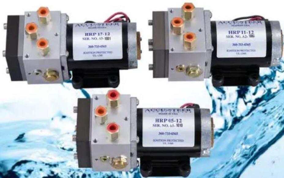
REVERSING PUMPSET
HRP05 • HRP11 • HRP17
TABLE OF CONTENTS
- GENERAL INFORMATION ...... p. 01
- TECHNICAL SPECIFICATIONS and APPLICATION ..... p. 02
- DESCRIPTION ...... p. 03
3.1 General
3.2 Motor
3.3 Pump
3.4 Valve Block and Valves
- INSTALLATION ...... p. 05
4.1 Mechanical
4.2 Hydraulic
4.3 Electrical
- PREPARATION and TESTING ...... p. 07
5.1 Hydraulic Filling and Testing
5.2 Testing
- NOTES p. 08
- DRAWINGS ...... p. 09
7.1 HRP05 • HRP11 • HRP17 — Assembly Schematic
7.2 HRP05 • HRP11 • HRP17 — System Connection Schematic
- CYLINDER — PUMP REFERENCE GUIDE ...... p. 11
1. GENERAL INFORMATION
A hydraulic steering system consists of a hydraulic actuator (normally a cylinder) and one or more steering wheel pumps (helm pumps). As the steering wheel (helm pump) is turned in the port direction, hydraulic oil is pumped into the port hydraulic steering line. This oil is directed into the port side of the steering cylinder. As the cylinder moves to port, oil from the starboard side of the cylinder returns to the helm pump through the starboard hydraulic lines.
One end of the cylinder is fixed and the other end is connected to a tiller arm, which is connected to a rudder shaft. With this connection to a tiller arm the linear movement of the cylinder to port is changed to rotary movement, which turns the rudder and steers the vessel to port.
Moving the steering wheel to starboard produces the same re-action with oil being pumped out of the starboard line and returning through the port line. If more the one helm pump is used, a return/fill line must be installed to connect the cases of all the helm pumps together.
If an autopilot is to be installed, the hydraulic reversing pumpset is connected in the same manner as a helm pump with a port, starboard and a return/fill line.
The Accu-Steer HRP05, HRP11 and HRP17 are reversing pump units designed to interface a hydraulic steering system with electric or autopilot control. The output flow rate of the pumpset determines the speed of the steering cylinder. The HRP05 pumpset outputs 0.5 cu in/sec or 8.2 cubic centimeters per second. The HRP11 pumpset outputs 1.0 cu in/sec or 16.4 cc's/sec. The HRP17 outputs 1.6 cu in/sec or 26.3 cc's/sec.
Most steering cylinders are balanced, which means the volume of oil on both sides of the cylinder is equal. A steering cylinder is balanced when the piston rod of the cylinder protrudes from both ends. Some cylinders are unbalanced in which the piston rod protrudes from one end only. These are common on some in-board and out-board drives and are usually referred to as side drives or simply unbalanced cylinders. These Accu-Steer HRP pumpsets are capable of working with both balanced and unbalanced cylinders. When unbalanced cylinders are used it is recommended that a vented header tank is used to allow for the expansion and contraction from the unbalanced cylinder.
2. TECHNICAL SPECIFICATIONS and APPLICATION
| MODEL HRP | 05-12 | HRP 11-12 | HRP 17-12 | HRP 05-24 | HRP 11-24 | HRP 17-24 |
| VOLTAGE 12 VDC 12 | VDC 12 VDC 24 VDC 24 VDC | |||||
| OUTPUT/SEC 0.5 cu | in 1.0 cu in 1.6 cu in 0.5 cu in 1.0 cu in 1.6 cu in | |||||
| AVERAGE AMP 3-5 | 4-6 5-8 2-4 3-5 3-5 | |||||
| WEIGHT (lbs/kgs) | 10/4.5 10/4.5 10/4.5 10/4.5 10/4.5 | |||||
The output flow rate of an electric pumpset determines the maximum speed of the rudder. Under normal conditions a rudder speed of 10 to 16 seconds will provide the best steering results for most autopilot systems. It is therefore important to select the proper pumpset to optimize your autopilot operation.
First determine the volume of your steering cylinder. This is usually indicated in the instruction manual of your steering system. Enclosed at the back of this manual are lists of various steering cylinder manufacturers with their cylinder models and volumes.
If you have to calculate the volume of your cylinder manually you can use the following formula:
$$ \text { Volume } = \mathrm{L} (\mathrm{D} ^ {2 - \mathrm{d} ^ {2}}) \pi \div 4 $$
Where:
$$ \begin{array}{l} L = \text { length of stroke of cylinder } \ D = \text { internal diameter of cylinder } \ d = \text { diameter of piston rod } \ \pi = 3. 1 4 (\mathrm{Pi}) \ \end{array} $$
The rudder speed, hard over to hard over (HOH), is determined by dividing the volume (cu in) of the cylinder by the output of the pumpset (cu in/sec). For example: a 15 cu in cylinder speed would be approximately 14 seconds HOH using an HRP11 or approximately 9 seconds using and HRP17.
3. DESCRIPTION
3.1 GENERAL
The Accu-Steer HRP05, HRP11 and HRP17 are complete pump assemblies each consisting of a reversing gerotor gear pump, hydraulic lock valves, suction make-up check valves, a valve housing manifold and an electric permanent magnet motor.
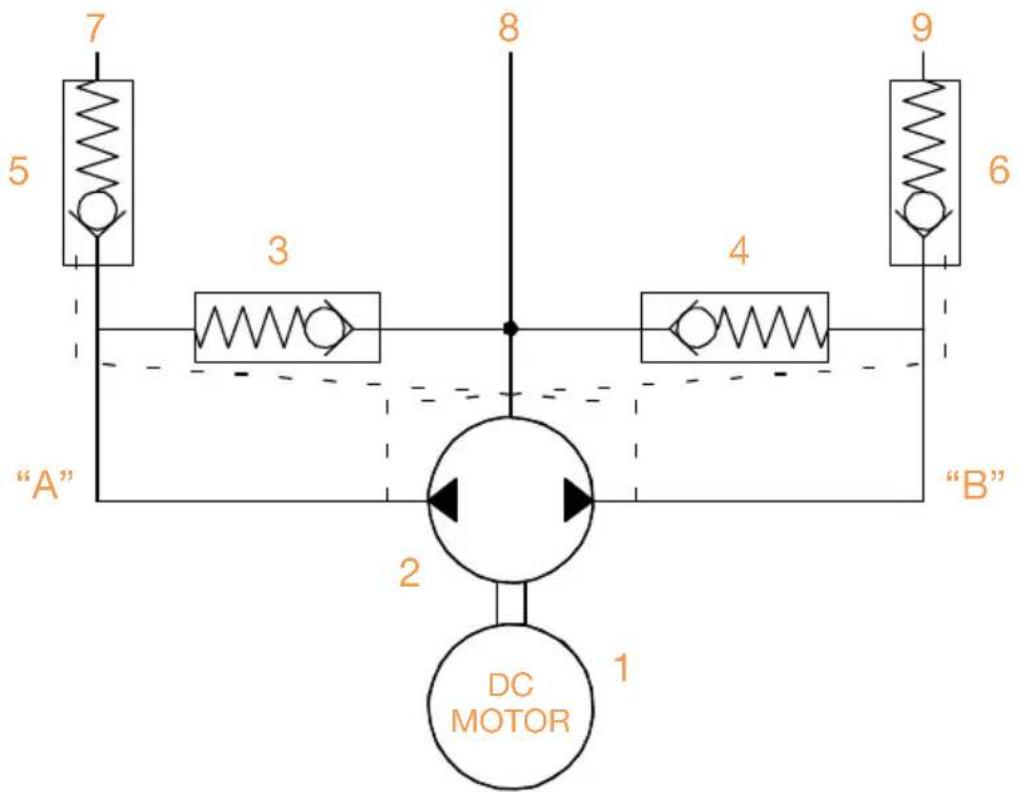
FIGURE 3.1 HYDRAULIC SCHEMATIC
flowchart
graph TD
    A["7"] --> B["5"]
    B --> C["3"]
    C --> D["8"]
    D --> E["4"]
    E --> F["9"]
    F --> G["6"]
    G --> H["B"]
    H --> I["2"]
    I --> J["DC MOTOR 1"]
    style A fill:#f9f,stroke:#333
    style B fill:#f9f,stroke:#333
    style C fill:#f9f,stroke:#333
    style D fill:#f9f,stroke:#333
    style E fill:#f9f,stroke:#333
    style F fill:#f9f,stroke:#333
    style G fill:#f9f,stroke:#333
    style H fill:#f9f,stroke:#333
    style I fill:#ccf,stroke:#333
    style J fill:#ccf,stroke:#333
Lines A and B are the output (port and starboard) lines, which are connected to steering lines on the vessel. Line T is the tank suction make-up or return line. These lines are clearly marked on the valve housing. Do not connect the output lines to the tank (T) port.
The HRP (Hydraulic Reversing Pumpset) operates as follows:
- As the motor (1) rotates CCW, oil from the gear pump (2) is pumped towards output "A".
- This oil passes through the check valve (5) and goes to the line output (7).
- The pressure at output "A" ensures the check valve (3) stays closed and manually opens check valve (6).
- Opening check valve (6) allows the returning oil from the steering cylinder to flow back to the pump.
- If the pressure at the pump suction “B” is less than the pressure in the make-up line, oil from the make up line will pass by the check valve (4). This prevents cavitation due to any air that may be in the steering line.
- When the pump stops turning all spring-loaded check valves return to the normally closed position.
- When the motor (1) rotates (CW) the reverse movement of the oil and valves takes place.
3.2 MOTOR
A list of features:
- Ignition protected (UL 1500 and SAE-1171).
• Ball bearing shaft supports both ends. - Extended motor shafting eliminating the pump/motor coupling.
• Machined pilot bore ensuring aligned pump/motor adapter mounting.
• Cushioned foot mounts for quiet operation.
• Opposite end shaft mount for tachometer/encoder.
3.3 PUMP
A list of features:
- The reversing gear pumps (HRP's) use gerotor style pump unit. The gerotor gear was used because of its quiet operation and its efficient pumping capabilities.
- The gears are driven directly from the extended motor shaft which eliminate the need for a pump/motor shaft coupling.
- The shaft is supported by the motor ball bearing on one side and a hard anodized aluminum end plate on the other side.
- The gerotor pump is a two-piece gear assembly with an eccentric ring. Proper clearances and alignments are maintained through CNC precision machining.
- Valve block sealing is accomplished using O-ring style seals.
- The shaft seal is accomplished using a rubber shaft seal rated at 50 psi. This shaft seal is connected to the tank/return line pump chamber. If this tank port is connected to a steering line or is over pressurized, it may cause this seal to fail. See the installation instructions for more details.
3.4 VALVE BLOCK and VALVES
A list of features:
- The valve block is an aluminum block, precision machined to house the valves, direct the oil and serve as the endplate for the gear pump. The pump end plate is referenced to the valve block with locator pins to ensure the proper alignment.
- The suction make-up valves are located between the return line port and the pump output internal ports. These allow the pump to “breathe” properly in the event of air from the steering lines entering the pumpset.
- The output check valves are part of what is called a lock-valve assembly. The lockvalve assembly consists of two output check valves and a lockvalve spool. In the non-running position the spring operated check valves remain closed, isolating the pump from the steering system. The spring action of the check valves holds the lockvalve spool in the mid-closed position.
- The end plate houses the pump shaft guide and aligns the pump.
4. INSTALLATION
4.1 MECHANICAL
The pumpset should be placed on a horizontal shelf or bracket with a solid foundation. The pump can be bolted or screwed down with the motor foot bracket. The foot bracket is fitted with anti-vibration mounts to maintain the quiet operation of the pumpset. The pumpset should be close to and below the steering lines for ease of connections and bleeding.
4.2 HYDRAULIC
Before connection to the hydraulic lines, ensure all hydraulic lines in the steering system are clean and free of contaminating particles, which could enter the pump and cause it to fail.
Most steering manufacturers have recommended hydraulic oils to be used in their systems. The HRP pumpsets are compatible with these oils. Most manufacturers use an ISO #32 or ISO #10 type of oil.
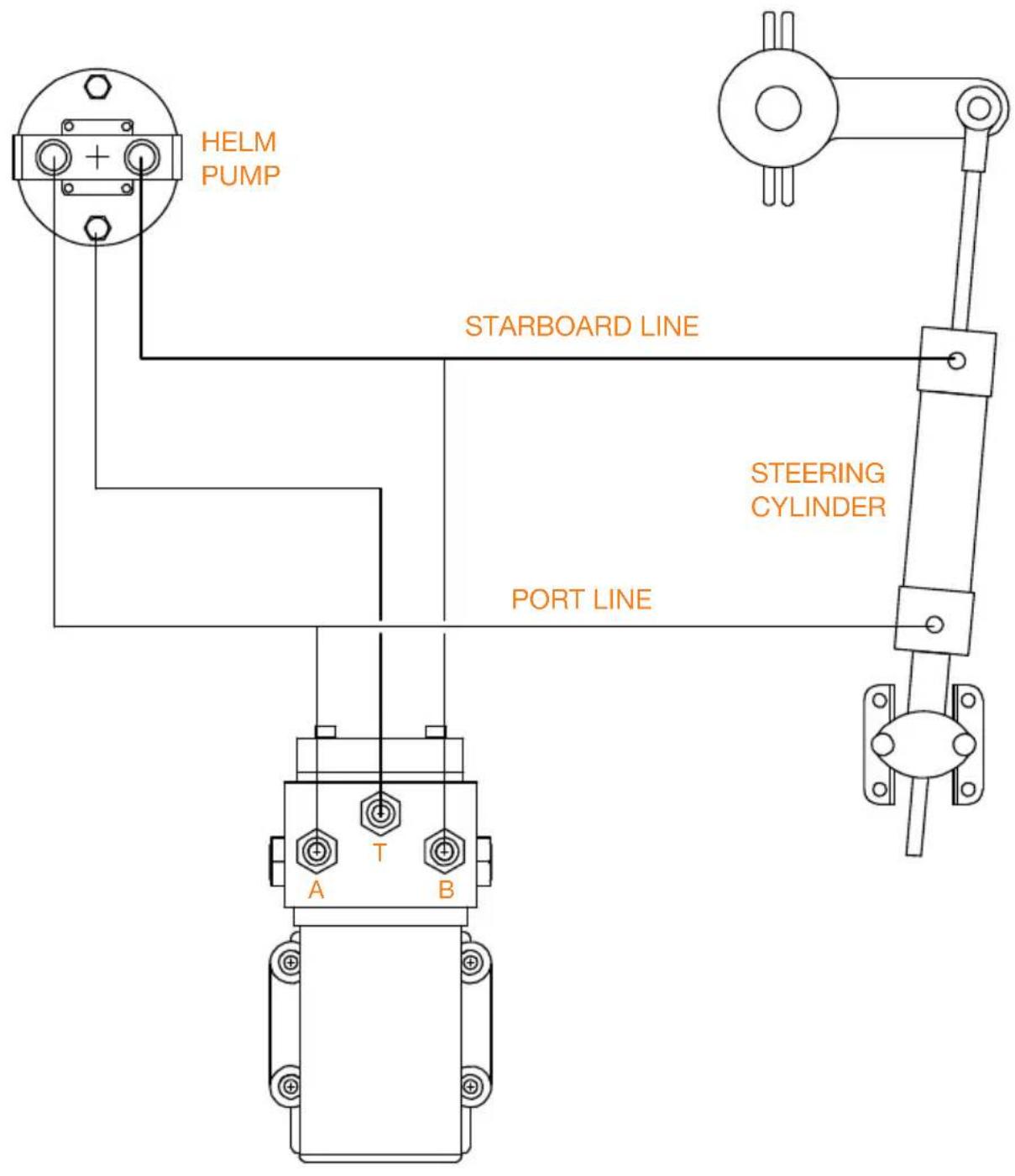
Three hydraulic connections are required to the pumpset. Two lines connect the pump (outputs A and B) to the main steering (port and starboard) lines.
It is not critical to identify which of the steering lines is port or starboard as most new autopilots will determine the pump direction and program the drive outputs to suit. For older autopilots the motor leads can be reversed to change the pumps direction. The third line, which is the interconnect or fill line, connects the pumpset to the header tank or helm pump case. This third line is critical, as it provides make up oil and allows the pumpset to vent any air, which may enter the pumpset from the steering lines. It is recommended that flex hose be used for all three lines to prevent any pump noise from being transmitted to the steering system. The port and starboard steering lines should have a pressure rating of 1000 psi minimum; where the third fill/interconnect line is a non-pressurized line. Shut-off or isolation valves for all three lines are recommended. If the pumpset fails, the isolation valves can be shut off and manual steering maintained.
The three hydraulic connections on the valve block are 9/16"-18 UNF (ORB -06) threads and are fitted with adapter to 1/4" NPT (National Pipe Thread). If installers prefer the adapters can be removed and connections can be made directly to the valve block. When installing the hydraulic fitting in the 1/4" NPT connection a pipe thread sealant such as Teflon paste or tape must be used.
NOTE OF CAUTION is important that the port or starboard line does not become crossed with the fill/interconnect line as this could cause high pressure to be introduced into the pumps tank cavity. In steering systems where the fill/interconnect line is pressurized (e.g. - Hynautics or Teleflex) the recommended operating pressure is approximately 20 to 25 psi. The shaft seal on the HRP pumpsets is rated at 50 psi and is well within the pressure range of these steering systems. Over-pressurizing these steering systems and causing a shaft seal failure will void the warranty of the pumpset.
4.3 ELECTRICAL
The motor is a permanent magnet style motor. There are two leads, which connect to the autopilot pump driver junction box (processor). As mentioned previously the direction of the pumpset can be reversed by simply reversing the polarity of these two leads.
To test the operation of the HRP pumpset, touch the two leads from the motor to the supply voltage (12 VDC or 24 VDC) to jog the motor in one direction and then reverse the leads to jog the pumpset in the other direction. Use caution not to perform this operation where any combustible fumes exist.
The motors used on the HRP05, HRP11, and HRP17 pumpsets are ignition protected, built to conform to UL-1500 and SAE-1171 standards.
5. PREPARATION and TESTING
5.1 HYDRAULIC FILLING and TESTING
When installing a pumpset it is recommended that the system be flushed to ensure that the oil is clean and free of contamination through out the hydraulic steering system.
After the hydraulic and electrical connection have been made, open all valves if installed, and allow sufficient time for the pump and lines to fill with oil. Operate the pumpset and note the HOH time. This time varies with the type of steering system and autopilot used
5.2 TESTING
Set the autopilot to the manual mode and operate the pumpset to determine if the port and starboard directions are correct. If the rudder goes the opposite way, reverse the two electrical leads to the motor.
Most new autopilot systems will perform this test during their dockside set-up procedures.
6. NOTES
7. DRAWINGS
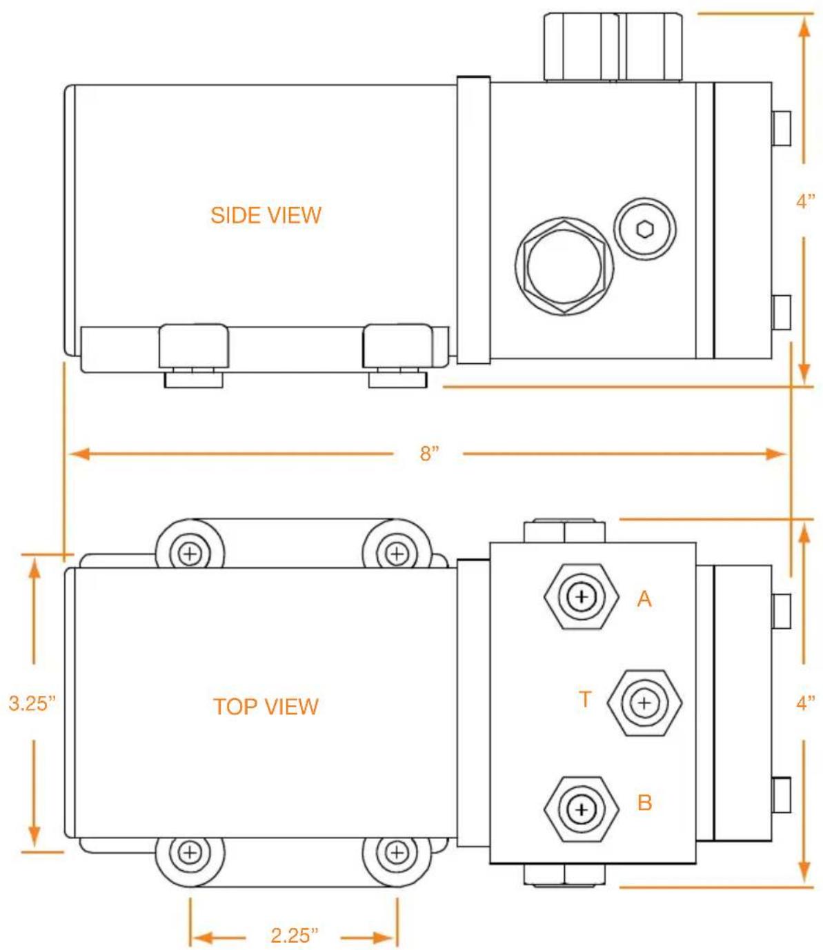
7.1 HRP05 • HRP11 • HRP17
ASSEMBLY SCHEMATIC
7.2 HRP05 • HRP11 • HRP17 SYSTEM CONNECTION SCHEMATIC
8. CYLINDER-PUMP REFERENCE GUIDE
Please read the following:
- The Accu-Steer HRP series of pumps are recommended for medium duty applications (<100 hours/month).
- The Accu-Steer HPU100 and up are recommended for heavy duty and work boat applications.
- The Accu-Steer HM series of hydraulic manifolds require an electric driven or engine driven pump unit.
- When 2 cylinders are used double the displacement volumes.
| STEERING MFR. | CYLINDER MODEL | BORE/ STROKE | CU IN DSPLT | ACCU-STEER PUMP “A” | ACCU-STEER PUMP “B” | COMMENTS |
| HYNAUTIC | PSK-10 6.0 HRPO5 | Power Steering | ||||
| K-1 1.50" x 9.00" 12.1 HRP11 | ||||||
| K-2 1.75" x 9.00" 17.6 HRP11 HRP17 | ||||||
| K-3 2.00" x 9.00" 23.1 HRP17 HRP75 | ||||||
| K-4 2.00" x 12.0" 30.5 HRP75 | ||||||
| K-5 2 x CYL'S 25.5 HRP17 HRP75 | ||||||
| K-6 CTR MNT 9.0 HRP05 HRP11 | ||||||
| K-7 1.50" x 9.50" 12.6 HRP11 | ||||||
| K-8 2.50" x 9.50" 39.2 HRP75 | ||||||
| K-9 2.50" x 14.25" 54.0 HRP75 | ||||||
| K-10 1.25" x 9.50" 7.5 HRP05 | ||||||
| K-11 1.25" x 9.00" 11.0 HRP11 | ||||||
| K-12 1.25" x 7.00" 8.6 HRP05 | ||||||
| K-13 1.25" x 9.00" 11.0 HRP11 | ||||||
| K-14 1.25" x 7.00" 8.6 HRP05 | ||||||
| K-16 1.25" x 9.00" 11.0 HRP11 | ||||||
| K-18 1.25" x 7.00" 7.0 HRP05 | ||||||
| K-19 1.25" x 9.00" 9.0 HRP05 HRP11 | ||||||
| K-21 1.50" x 9.00" 12.1 HRP11 | ||||||
| K-22 1.50" x 10.00" 13.3 HRP11 | ||||||
| K-24 1.50" x 6.00" 6.6 HRP05 | ||||||
| K-25 1.50" x 10.00" 13.3 HRP11 | ||||||
| K-26 1.50" x 12.00" 16.0 HRP11 HRP17 | ||||||
| HYNAUTIC K-27 1.50" x 1 | 0.00" 13.3 HRP | 11 | ||||
| K-28 1.50" x 12.00" 16.0 | HRP11 | HRP17 | ||||
| K-29 1.50" x 12.00" 16.0 | HRP11 | HRP17 | ||||
| K-31 2.00" x 10.0" 25.5 | HRP17 | HRP75 | ||||
| K-32 2.00" x 8.00" 20.0 | HRP17 | HRP75 | ||||
| K-33 2.00" x 9.00" 23.1 | HRP17 | HRP75 | ||||
| K-51 1.50" x 7.00" 10.2 | HRP11 | |||||
| JASTRAM B-125-7 1.25" x 7.00" 6.4 HRP | INBOARD/OUTBOARD | |||||
| B-125-9 1.25" x 9.00" 8.2 | HRP05 | INBOARD/OUTBOARD | ||||
| B-125-7 1.25" x 7.00" 6.4 | HRP05 | |||||
| B-125-9 1.25" x 9.00" 8.2 | HRP05 | |||||
| B-150-7 1.50" x 7.00" 10.2 | HRP11 | |||||
| B-150-9 1.50" x 9.00" 13.1 | HRP11 | |||||
| B-200-12 2.00" x 12.00" 31.9 | HRP75 | |||||
| B-200-15 2.00" x 15.00" 39.1 | HRP75 | HPU100 | ||||
| B-300-9 3.00" x 9.00" 52.4 | HRP75 | HPU100 | ||||
| B-300-12 3.00" x 12.00" 69.9 | HPU200 | |||||
| B-300-16 3.00" x 16.00" 93.2 | HPU200 | |||||
| B-300-20 3.00" x 20.00" 116.6 | HPU200 | HPU300 | ||||
| K-1 | N/A | 10.0 | HRP75 | HPU100 | HEAVY DUTY APPLIC. | |
| K-3 | N/A | 20.0 | HRP75 | HPU100 | HEAVY DUTY APPLIC. | |
| K-4 | N/A | 31.0 | HRP75 | HPU100 | HEAVY DUTY APPLIC. | |
| K-5 N/A | 42.0 HPU100 | HEAVY DUTY APPLIC. | ||||
| K-6 N/A | 54.0 HPU200 | HEAVY DUTY APPLIC. | ||||
| K-7 N/A | 54.0 HPU200 | HEAVY DUTY APPLIC. | ||||
| MAROL | MCS-26 | N/A | 3.9 | HRP05 | ||
| MCS-26T | N/A | 3.9 | HRP05 | |||
| MCS-28 | N/A | 5.5 | HRP05 | |||
| MCS-28T | N/A | 5.5 | HRP05 | |||
| MCB-35F | N/A | 8.5 | HRP05 | |||
| MCB-42L | N/A | 17.4 | HRP11 | HRP17 | ||
| MRB-50 | N/A | 2.6 | HRP05 | LEVER RATIO = 0.74 : 1.00 | ||
| MAROL MR | RB-50 N/A 3.7 | HRPO5 | LEVER RATIO = 0.74 : 1.00 | |||
| MRB-50 N/A | 4.8 HRP05 | LEVER RATIO = 1.00 : 1.00 | ||||
| MRB-63 N/A | 5.1 HRP05 | LEVER RATIO = 1.23 : 1.00 | ||||
| MRB-63 N/A | 7.1 HRP05 | LEVER RATIO = 1.00 : 1.00 | ||||
| MRB-63 N/A | 9.3 HRP05 HRP11 | LEVER RATIO = 1.23 : 1.00 | ||||
| MRB-75 N/A | 10.6 HRP11 | LEVER RATIO = 0.74 : 1.00 | ||||
| MRB-75 N/A | 14.7 HRP11 | LEVER RATIO = 1.00 : 1.00 | ||||
| MRB-75 N/A | 19.2 HRP17 | LEVER RATIO = 1.23 : 1.00 | ||||
| MRB-80 N/A | 18.7 HRP17 | LEVER RATIO = 1.00 : 1.00 | ||||
| MRB-80 N/A | 24.2 HRP17 HRP75 | LEVER RATIO = 1.23 : 1.00 | ||||
| MRB-100 N/A | 20.9 HRP17 HRP75 | LEVER RATIO = 0.74 : 1.00 | ||||
| MRB-100 N/A | 29.3 HRP75 | LEVER RATIO = 1.00 : 1.00 | ||||
| MRB-100 N/A | 37.7 HRP75 | LEVER RATIO = 1.23 : 1.00 | ||||
| MORSE HS | $3000 1.25" x | 7.00" 6.55 HRP | 05 | INBOARD CYLINDER | ||
| HS4000 1.57" x | 7.00" 11.48 | HRP11 | INBOARD CYLINDER | |||
| HS5000 1.77" x | 6.70" 13.53 | HRP11 | INBOARD CYLINDER | |||
| HS SINGLE N/A | 8.0 HRP05 | OUTBOARD CYLINDER | ||||
| HS DOUBLE | N/A | 16.0 | HRP11 | OUTBOARD CYLINDER | ||
| T-TRQUE | TTDS-175 | N/A 16.0 | HRP17 | HRP75 | ||
| TTDS-200 | N/A 16.0 | HRP17 | HRP75 | |||
| TTDS-250 | N/A 32.0 | HRP75 | ||||
| TTDS-300 | N/A 32.0 | HRP75 | ||||
| TTDS-400 | N/A 32.0 | HRP75 | ||||
| TELEFLEX 1 | 25-8EM 8.4 / | 9.8 | HRP05 HRP11 | UNBALANCED CYLINDER | ||
| 125-8VEM 8.4 / | 9.8 | HRP05 HRP11 | UNBALANCED CYLINDER | |||
| 92-VPS 9.8 / | 11.6 | HRP05 HRP11 | UNBALANCED CYLINDER | |||
| BA125-7 1.25" x 7.00" 7.2 HRP05 | ||||||
| BA125-8 1.25" x 8.00" 9.0 HRP05 HRP11 | ||||||
| BA135-7 1.35" x 7.00" 8.2 HRP05 | ||||||
| BA135-8 1.35" x 8.00" 9.4 HRP05 HRP11 | ||||||
| BA150-7 1.50" x 7.00" 10.2 HRP11 | ||||||
| BA175-7 1.75" x 7.00" 13.7 HRP11 | ||||||
| BA200-7 2.00" x 7.00" 18.9 HRP17 | ||||||
| BA200-11 2.00" x 11.00" 29 7 HRP17 HRP75 | ||||||
| HC5342 8.1 HRP05 | OUTBOARD CYLINDER | |||||
| HC5345 8.1 HRP05 | OUTBOARD CYLINDER | |||||
| HC5345 6.8 HRP05 | OUTBOARD CYLINDER | |||||
| HC5370 8.1 / | 9.7 | HRP05 HRP11 | UNBALANCED CYLINDER | |||
| HC5380 9.4 / | 11 | HRP05 HRP11 | UNBALANCED CYLINDER | |||
| WAGNER | N50-190 | 50 x 190 mm 19.1 HRP17 | ||||
| N50-300 | 50 x 300 mm 30.2 HRP75 | |||||
| N80-190 | 80 x 190 mm 49.0 HRP75 HPU100 | HEAVY DUTY APPLIC. | ||||
| N80-300 | 80 x 300 mm 77.3 HPU200 | HEAVY DUTY APPLIC. | ||||
| N80-400 | 80 x 400 mm 103.0 HPU200 | HEAVY DUTY APPLIC. | ||||
| N65 | 2.00" x 11.00" 6.0 HRP05 | |||||
| N85 | 2.00" x 11.00" 7.8 HRP05 | |||||
| N175-750 | 1.75" x 7.50" 14.8 HRP11 | |||||
| N175-1000 | 1.75" x 10.00" 19.7 HRP17 | |||||
| N250-800 | 2.50" x 8.00" 33.0 HRP85 | |||||
| N250-1000 | 2.50" x 10.00" 41.2 HRP75 HPU100 | HEAVY DUTY APPLIC. | ||||
| N250-1300 | 2.50" x 13.00" 53.6 HRP75 HPU100 | HEAVY DUTY APPLIC. | ||||
| N350-1200 | 3.50" x 12.00" 94.2 HPU200 | HEAVY DUTY APPLIC. | ||||
| N350-1600 | 3.50" x 16.00" 125.6 HPU300 HM250 | HEAVY DUTY APPLIC. | ||||
| WAGNER | N400-1500 | 4.00" x 15.00" | 152.4 HPU300 HM250 | HEAVY DUTY APPLIC. | ||
| N400-2000 | 4.00" x 20.00" | 203.2 HM400 | HEAVY DUTY APPLIC. | |||
| T2 | N/A 16.0 HRP75 HPU100 | HEAVY DUTY APPLIC. | ||||
| T3 | N/A 20.4 HRP75 HPU100 | HEAVY DUTY APPLIC. | ||||
| T4 | N/A 30.5 HRP75 HPU100 | HEAVY DUTY APPLIC. | ||||
| T5 | N/A 41.6 HPU100 | HEAVY DUTY APPLIC. | ||||
| T10 | N/A 54.2 HPU100 | HPU200 | HEAVY DUTY APPLIC. | |||
| T11 | N/A 54.2 HPU100 | HPU200 | HEAVY DUTY APPLIC. | |||
| T12 | N/A 77.1 HPU200 | HEAVY DUTY APPLIC. | ||||
natural_image
Abstract water splash effect with blue bubbles and droplets on white background (no text or symbols)STAYING TRUE TO YOUR COURSE.
Accu-Steer, Inc.
Accu-Steer, Inc. • Marina Square 704 Coho Way • Bellingham, WA 98225
(360) 733-4565, telephone • (360) 733-4575, fax
cs@Accu-Steer.com • www.Accu-Steer.com
Instruction Manual
HRP Series
HRP05·HRP11·HRP17
- Defining Reliability
- Instruction Manual
- HRP SERIES
- REVERSING PUMPSET
- HRP05 • HRP11 • HRP17
- TABLE OF CONTENTS
- GENERAL INFORMATION
- TECHNICAL SPECIFICATIONS and APPLICATION
- DESCRIPTION
- GENERAL
- MOTOR
- PUMP
- VALVE BLOCK and VALVES
- INSTALLATION
- MECHANICAL
- HYDRAULIC
- ELECTRICAL
- PREPARATION and TESTING
- HYDRAULIC FILLING and TESTING
- TESTING
- NOTES
- DRAWINGS
- HRP05 • HRP11 • HRP17
- ASSEMBLY SCHEMATIC
- HRP05 • HRP11 • HRP17 SYSTEM CONNECTION SCHEMATIC
- CYLINDER-PUMP REFERENCE GUIDE
Brand : FURUNO
Model : HRP17
Category : Radar maritime