
1731 Mark-3 - Radar maritime FURUNO - Free user manual and instructions
Find the device manual for free 1731 Mark-3 FURUNO in PDF.


| Product Type | Marine Radar |
| Brand | Furuno |
| Model | 1731 Mark-3 |
| Display Size | 12-inch CRT |
| Transmitter Power | 4 kW |
| Radar Range | Up to 36 nautical miles |
| Antenna Type | Open array, 3.5 ft |
| Scan Speed | 24 rpm |
| Dimensions (Display Unit) | Approx. 380 x 380 x 300 mm |
| Weight (Display Unit) | Approx. 12 kg |
| Power Supply | 10-40 V DC, 24 V nominal |
| Power Consumption | Approx. 100 W |
| Operating Temperature | -15°C to +55°C |
| Waterproof Rating | IPX6 (display unit) |
| Key Features | Automatic tuning, rain clutter control, sea clutter control, target enhancement, guard zone alarm |
| Maintenance | Clean display screen with soft, dry cloth; periodically check antenna and cable connections |
| Safety | Do not expose to excessive moisture; ensure proper grounding; follow installation guidelines |
| Spare Parts and Repairability | Contact authorized Furuno service centers for genuine spare parts and repairs |
| General Information | Compact and reliable radar system suitable for small to medium vessels |
Frequently Asked Questions - 1731 Mark-3 FURUNO
User questions about 1731 Mark-3 FURUNO
0 question about this device. Answer the ones you know or ask your own.
Ask a new question about this device
Download the instructions for your Radar maritime in PDF format for free! Find your manual 1731 Mark-3 - FURUNO and take your electronic device back in hand. On this page are published all the documents necessary for the use of your device. 1731 Mark-3 by FURUNO.
USER MANUAL 1731 Mark-3 FURUNO
All rights reserved.
Printed in Japan
(HIMA)
PUB. No. OME-34450
MODEL1731 MARK-3
-Your Local Agent/Dealer
FIRST EDITION : FEB. 1997
J
JUN.
6,20(
* 00080792800 *

SAFETY INSTRUCTIONS
"DANGER", "WARNING" and "CAUTION" notices appear throughout this manual. It is the responsibility of the operator and installer of the equipment to read, understand and follow these notices. If you have any questions regarding these safety instructions, please contact a FURUNO agent or dealer.

DANGER
This notice indicates a potentially hazardous situation which, if not avoided, will result in death or serious injury.

WARNING
This notice indicates a potentially hazardous situation which, if not avoided, could result in death or serious injury.

CAUTION
This notice indicates an unsafe practice which, if not avoided, could result in minor or moderate injury, or property damage.

WARNING

Hazardous voltage.
Can shock, burn, or cause death.
Only qualified personnel should work in the unit.
Turn off the power at the ship's mains switchboard before beginning the installation. Post a warning sign near the switchboard to ensure the power will not be applied while the radar system is being installed.
Electrical shock, fire, serious injury or death can result if the power is not turned off, or is applied while the equipment is being installed.

CAUTION
Ground both the display unit and the antenna unit.
Ungrounded equipment can give off or receive interference or cause electrical shock.
Confirm that the power supply voltage is compatible with the voltage rating of the equipment.
Connection to the wrong power supply can cause fire or equipment damage. The voltage rating appears on the label at the rear of the display unit.
Use only the supplied power cable.
Use of other power cables (particularly a cables whose diameter is smaller than the supplied cable) can cause fire or short circuit.
Use the correct fuse.
Use of a wrong fuse can cause fire or equipment damage.
NOTICE
The installation must be done by a FURUNO representative or suitably qualified radar technician.
Authorities require this.
The mounting location must satisfy the following conditions:
- Useable temperature: -15°C to 55°C
• Out of direct sunlight
• Away from air conditioner vents - Well ventilated
Observe the compass safe distances to prevent deviation of a magnetic compass.
| Standard compass | Steering compass | |
| Display Unit | 0.5 m | 0.4 m |
| Scanner Unit | 0.9 m | 0.7 m |
Keep magnets and magnetic fields away from the equipment.
Magnetic fields will distort the picture and can cause equipment malfunction. Be sure the unit is well away from equipment which gives off magnetic fields (speaker, power transformer, etc.).
Please Check Input Voltage
This radar can operate by input voltage of 12VDC or 24/32VDC. If not specified when ordering, the unit comes ready for 12VDC connection. For 24/32VDC ship's mains, replace a fuse in the display unit. The amperage of the fuse (F1351) at the rear of the display unit should be;
| Ship's Mains | Fuse F1351 |
| 12VDC | 10A |
| 24/32VDC | 5A |
Note: Spare fuses are supplied as spare parts.
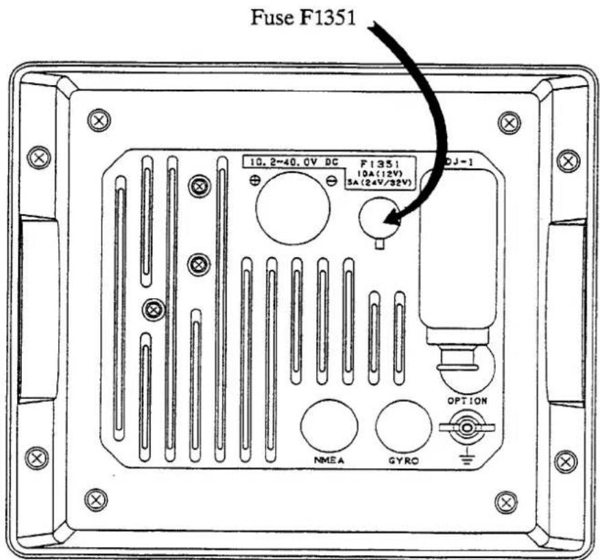
Display Unit, Rear View
Table of Contents
FOREWORD ...... v
GENERAL SAFETY INFORMATION ...... vi
OPERATING PRECAUTIONS ...... vi
FEATURES......vii
SPECIFICATIONS ix
1. PRINCIPLE OF OPERATION.... 1-1
2. OPERATIONAL OVERVIEW 2-1
THE FRONT PANEL 2-1
Description of controls 2-2
TURNING THE UNIT ON AND OFF 2-4
BASIC OPERATION 2-4
Range selection 2-5
Adjusting the GAIN control 2-6
Adjusting the A/C SEA control 2-7
Tuning the radar receiver 2-8
Adjusting display brightness 2-8
Adjusting front panel backlighting 2-8
Erasing the heading mark 2-8
REDUCING INTERFERENCE 2-13
Precipitation clutter 2-13
Radar interference 2-14
SHIFTING AND ZOOMING THE DISPLAY 2-15
Shift 2-15
Zoom 2-15
GUARD ALARM 2-16
Auto in/out alarm 2-18
PLOTTING 2-19
Plot brilliance 2-19
NAVIGATION DATA 2-20
BETTER DISTINCTION OF ECHOES 2-21
WATCHMAN 2-22
3. APPLICATION 3-1
FACTORS AFFECTING MINIMUM RANGE 3-1
Sea return 3-1
Vertical beamwidth 3-1
FACTORS AFFECTING MAXIMUM RANGE 3-2
Radar horizon 3-2
Target properties 3-3
INTERPRETING THE DISPLAY 3-4
Land targets 3-4
Ship targets 3-5
Echo size 3-5
FALSE ECHOES 3-6
Multiple echoes 3-6
Side-Lobe echoes 3-6
Blind and shadow sectors 3-7
Indirect echoes 3-7
RADAR PICTURE AND CORRESPONDING CHART 3-8
POSITION FIXING WITH RADAR 3-9
By radar range 3-9
By range and bearing to a point of land 3-9
By two bearings 3-10
COLLISION AVOIDANCE AND RELATIVE MOTION 3-11
Assessing the risk 3-12
- MAINTENANCE....4-1
GENERAL 4-1
SCANNER UNIT 4-1
Radome 4-1
Mounting base 4-1
DISPLAY UNIT 4-2
Cleaning the display screen 4-2
Fuse replacement 4-2
- TROUBLESHOOTING....5-1
BASIC TROUBLESHOOTING 5-2
ADVANCED TROUBLESHOOTING 5-3
Typical problems and their causes 5-3
CHECKING THE MAGNETRON 5-4
- INSTALLATION 6-1
ANTENNA UNIT INSTALLATION 6-1
Siting, handle consideration 6-1
Mounting 6-1
DISPLAY UNIT INSTALLATION 6-4
Installation of rubber vibration isolators 6-5
Antenna connection 6-5
Power connection 6-
Ground connection 6-6
Gyrocompass (or heading sensor) connection (option) 6-6
External navigational receiver connection (option) 6-7
Fuse exchange for 24/32 VDC power supplies 6-7
CHECKING THE INSTALLATION 6-9
ADJUSTMENTS 6-10
Initial procedures 6-10
Sweep timing 6-10
Relative bearing alignment 6-12
MAG or GYRO indication 6-14
Range unit selection 6-14
Magnetron heater voltage 6-15
MEASUREMENT OF BLIND SHADOW SECTORS 6-18
LIST OF DRAWINGS....S-1
CIRCUIT DIAGRAMS
Declaration of Conformity
This page intentionally left blank.
FOREWORD
Congratulations on your choice of the FURUNO Model 1731 MARK-3 Radar. We are confident you will see why the FURUNO name has become synonymous with quality and reliability.
For over 50 years FURUNO Electric Company has enjoyed an enviable reputation for quality and reliability throughout the world. This dedication to excellence is furthered by out extensive global network of agents and dealers.
The Model 1731 MARK-3 is just one of many Furuno developments in the field of radar. It is compact and lightweight and while it is suitable for use on a wide variety of vessels, you should consult with your Furuno dealer to determine whether it is suitable for use on a particular vessel. Your Furuno dealer can also advise you as to other Furuno radar units which you can purchase, depending on your particular needs and expected uses of the equipment.
This unit is designed and constructed to give the user many years of trouble-free operation. However, please do not attempt to install, operate or conduct any maintenance before carefully reading and following the recommended procedures set forth in this manual.
While this unit is generally easy to install by following the enclosed installation directions, any purchaser who has doubts about his or her technical abilities may wish to have this unit installed by a Furuno representative or other qualified technician. This unit can perform its intended functions only when properly installed (and maintained).
We would appreciate feedback from you, the end-user, about whether we are achieving our purposes.
Thank you for considering and purchasing Furuno equipment.
General Safety Information
Be sure to read all the safety information which follows before attempting to install, operate or maintain your radar.
"DANGER," "WARNING," and "CAUTION" notices appear throughout this manual. It is the responsibility of the user of this equipment to read, understand and follow these notices. If you have any questions regarding these safety instructions, please contact a Furuno agent or dealer.
Operating Precautions
■ Navigation is a complex and detailed skill which requires knowledge, judgment and experience to perform effectively. Errors in navigation can lead to catastrophic injury or even death in some circumstances. Navigational errors can cause collisions between vessels, collisions with land and land-based structures, and can lead to being lost at sea.
Although this manual explains much about the operation of the radar and how it can aid in the navigation of your vessel, it is not a substitute for practical experience, seamanship or formal training. It is, therefore, recommended that you work to develop this skill by enrolling in a course in navigation taught by a qualified maritime school.
■ No single navigational aid (including this radar) should ever be relied upon as the exclusive method for navigating your vessel. The navigator is responsible for checking all aids available to confirm his position. Electronic aids are meant to assist the navigator, not replace him.
■ The 1972 Convention on the International Regulations for Preventing Collisions at Sea (1972 COLREGS) provide statutory requirements for the operation of any vessel including the posting of lookouts. The operator of the vessel is responsible for compliance with these requirements whether or not the radar is in use.
Features
Your unit has a large variety of functions, all contained in a remarkably small cabinet.
- All controls respond immediately to the operator's command and each time a touchpad is pressed, the corresponding change can be seen on the screen.
- Daylight viewing radar especially designed for small craft and sailing yachts.
• Traditional FURUNO reliability and quality in a compact, lightweight and low-cost radar.
- Compact and lightweight radome antenna with precision 54 cm center-fed radiator.
• High definition 18 centimeter raster-scan display.
- 8 levels of target quantization for high target definition without problems associated with single-level quantization systems.
• Automatic tuning for easy operation.
- Main function controlled with touchpads, while less often used functions controlled thru "Menu" display.
- On-screen alpha-numeric readout of all operational information.
- Near maintenance-free design enhances reliability.
• Maximum fourteen ranges from 0.25 to 36 nautical miles.
- 3 pulselengths and pulse repetition rates automatically selected, for optimum short-range to long-range performance.
- EBL (Electronic Bearing Line), VRM (Variable Range Marker), Guard Alarm and Cursor controlled by a trackball.
- Guard zone alarm, shift and zoom provided as standard features.
- "Watchman" feature periodically transmits the radar to check for radar targets which may be approaching own ship.
- Operates on 10.2 to 40.0VDC power supply and consumes only 47W. A unique "Economy" mode provided to reduce power consumption to 25W during stand-by periods. Protection against reverse polarity and excessive voltage provided.
- Ship's position in latitude/longitude (or Loran C time differences (TDs)), range/bearing to a waypoint, ship's speed, heading and course optionally shown in the bottom text area. (External navigator which can output such data in NMEA0183 or FURUNO CIF format required.)
This page intentionally left blank.
SPECIFICATIONS
SCANNER UNIT
- Radiator: Printed array
- Radiator Length: 60cm
- Horizontal Beamwidth: 3.9°
- Vertical Beamwidth: 20°
- Sidelobe Attenuation: Within ± 20° of mainlobe: -18dB or less Outside ± 20° of mainlobe: -23dB or less
- Polarization: Horizontal
- Antenna Rotation: 24 rpm nominal
TRANSCEIVER MODULE (contained in radome)
- Transmitting Tube: Magnetron 9M302/E3513
- Frequency & Modulation: 9410MHz ± 30MHz, P0N
- Peak Output Power: 3kW nominal
- Pulselength & Pulse Repetition Rate:
| Item\Range (nm) | 0.25 | 0.5 | 0.75 | 1 | 1.5 | 2 | 3 | 4 | 6 | 8 | 12 | 16 | 24 |
| Pulse Repetition Rate | Approx. 2100Hz | Approx. 1200Hz | Approx. 600Hz | ||||||||||
| Pulselength - | 0.08us | 0.3us | 0.8us | ||||||||||
- Modulator: FET Switching Method
- I.F.: 60MHz
- Tuning: Automatic
- Receiver Front End: MIC (Microwave IC)
- Bandwidth: 7MHz
- Duplexer: Circulator with diode limiter
- Noise Figure: 9dB nominal
DISPLAY UNIT
- Indication System: Raster scan, Daylight display
-
Picture Tube: 18-centimeter diagonal, green phosphor CRT
-
Range (nm, selectable):
-
Range Ring Interval (nm):
-
Number of Rings:
-
Bearing Resolution:
-
Bearing Accuracy:
-
Minimum Range:
-
Range Ring Accuracy:
-
VRM Accuracy:
-
Mark Indication:
-
Numeral/Character
cur
- Shift and Zoom:
14."Watchman" Mode:
- External Sig. In/Out Terminals:
Better than 1^
Better than 25m
0.9% or 8m, whichever is the greater.
0.9% or 8m, whichever is the greater.
Heading Mark, Bearing Scale, Range Ring, VRM, EBL, Tuning Bar, Alarm Zone, Cursor, North Mark
Range, Range ring interval, Pulselength (SP, MP LP), Display mode (HU, CU, NU, TM), Interference rejection (IR1, IR2, IR3), VRM (1, 2), EBL (1, 2), Automatic A/C SEA (A/CAUTO), Stand-by (ST-BY), Radar alarm (G/IN, G/OUT, G/ACKN), Echo stretch (ES1, ES2), Range to cursor, Bearing to cursor, Echo trailing (TRAIL), Trailing time, Trailing elapsed time, Navigation data (navigation input required), heading (HDG, heading sensor input required)
Built-in
Selectable thru menu
NMEA terminal (In)
GYRO terminal (In)
External Buzzer terminal (Out)
Monitor terminal (Out)
ENVIRONMENT CONDITION
- Vibration:
| Vibration Freq. | Total Amplitude |
| 1 to 12.5 Hz | ± 1.6 mm |
| 12 to 25 Hz | ± 0.35 mm |
| 25 to 50 Hz | ± 0.10 mm |
- Ambient Temperature:
Scanner Unit ---- -25°C to +70°C
Display Unit ---- -15°C to +55°C
- Humidity:
Relative humidity 95% or less at +40°C
POWER SUPPLY & POWER CONSUMPTION
12 V, 24 V or 3 2V (10.2 V to 41.6 VDC)
EQUIPMENT LIST
Complete Set
| No. | Name | ype Code No. | Qty | Remarks | |
| 1 Antenna Unit | t | RSB-0071-058 | 1 | ||
| 2 | Display Unit | RDP-099-31M3 | 1 | ||
| 3 | Spare parts | FP03-06000 | 000-085-153 | t | 1 se |
| 4 | Accessories | SP03-05800 | 000-080+923 | 1 | |
| 5 | Installation Material (Select one.) | CP03-18000 | 000-086-968 | t1 | Signal Cable: 10 m |
| CP03-18010 | 000-086-969 | Signal Cable: 15 m | |||
| CP03-18020 | 000-086-970 | Signal Cable: 20m | |||
| CP03-18030 | 000-086-971 | Signal Cable: 30 m | |||
Installation Materials (CP03-180xx)
| No. | Name | ype Code No. | Qty | Remarks | |
| 1 Hex. Bol t | M10X25 SUS304 | 000-862-308 | 4 | ||
| 2 | Flat Washer | M10 SUS304 | 008-864-131 | 4 | |
| 3 | Spring Washer | M10 SUS304 | 000-085-153 | 4 | |
| 4 | Tapping Screw | 6x20 SUS304 | 000-802-084 | 5 | |
| 5 Socket Ca p | 03-112-1254-1 | 100-159-441 | 1 | ||
| 6 | Signal Cable* (Select one.) | S03-70-10 | 008-475-260 | 1 | 10 m |
| S03-70-15 | 008-475-270 | 15 m | |||
| S03-70-20 | 008-475-280 | 20 m | |||
| S03-70-30 | 008-475-290 | 30 m | |||
| 7 | Power Cable | 03S7434 | 000-113-501 | 3.5 m | |
| 8 | EMC Core | E04SS251512 | 000-144-673 | 1 | |
S03-61 compatible may be supplied; two thin pink wires replaced with one thick wire.
Accessories
| No. | Name | ype Code No. | Qty | Remarks | |
| 1 Hood Ass y. | FP03-04601 | 008-428-620 | 1 | ||
| 2 Bracket Ass y. | FP03-04602 | 008-428-630 | 1 | ||
| 3 Knob Bol t | FP03-04603 | 008-428-640 | 2 | ||
Spare parts
| No. | Name | Type | Code No. | Qty | Remarks |
| 1 | Fuse | FGMB 10A 125VAC | 000-104-815 | 2 | For 12 VDC |
| 2 | Fuse | FGMB 5A 125VAC | 000-112-785 | 2 | For 24/32 VDC |
Accessories
| No. | Name | ype Code No. | Qty | Remarks | |
| 1 | Rectifier | RP-62 | 000-013-484 | 1 | 100 VAC |
| 000-013-485 | 110 VAC | ||||
| 000-013-486 | 220 VAC | ||||
| 000-013-487 | 230 VAC | ||||
| 2 | External Buzzer. | OP03-21 | 000-030-097 | 1 | |
| 3 Mountin g Bracket (1) | OP03-92 | 000-445-070 | |||
| 4 | Dast Cover | 03-028-0401 | 100-087-000 | 1 | |
1. PRINCIPLE OF OPERATION
The term "RADAR" is an acronym meaning RAdio Detection And Ranging. Although the basic principles of radar were developed during World War II, primarily by scientists in Great Britain and the United States, the use of echoes as an aid to navigation is not a new development.
Before the invention of radar, when running in fog near a rugged shoreline, ships would sound a short blast on their whistles, fire a shot, or strike a bell. The time between the origination of the sound and the returning of the echo indicated how far the ship was from the cliffs or the shore. The direction from which the echo was heard indicated the relative bearing of the shore.
Today, the method of determining the distance to a target is much more accurate because of pulse-modulated radar. Pulse-modulated radar determines the distance to the target by calculating the time difference between the transmission of a radar signal and the reception of the reflected echo. It is a known fact that radar waves travel at a nearly constant speed of 162,000 nautical miles per second. Therefore the time required for a transmitted signal to travel to the target and return as an echo to the source is a measure of the distance to the target. Note that the echo makes a complete round trip, but only half the time of travel is needed to determine the one-way distance to the target. This radar automatically takes this into account in making the range calculation.
The bearing to a target found by the radar is determined by the direction in which the radar scanner antenna is pointing when it emits an electronic pulse and then receives a returning echo. Each time the scanner rotates pulses are transmitted in the full 360 degree circle, each pulse at a slightly different bearing from the previous one. Therefore, if one knows the direction in which the signal is sent out, one knows the direction from which the echo must return.
Note that the speed of the radar waves out to the target and back again as echoes is extremely fast compared to the speed of rotation of the antenna. By the time radar echoes have returned to the scanner, the amount of scanner rotation after initial transmission of the radar pulse is extremely small.
The range and bearing of a target is displayed on what is called a Plan Position Indicator (PPI). This display is essentially a polar diagram, with the transmitting ship's position at the center. Images of target echoes (sometimes called a "pip") are received and displayed at their relative bearings, and at their distance from the PPI center.
With a continuous display of the images of targets, the motion of the transmitting ship is also displayed.
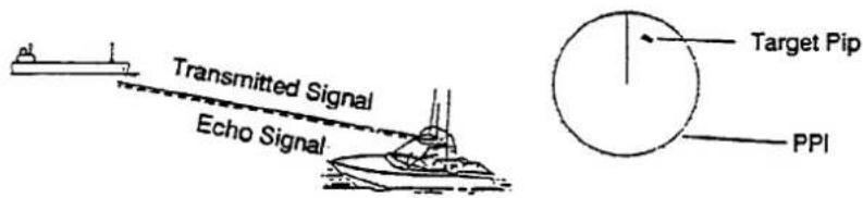
Figure 1-1 How Radar Works
2. OPERATIONAL OVERVIEW
CAUTION
To prevent possible bodily injury from Radio Frequency (RF) radiation hazards, always make sure that no person is near the scanner unit before turning on the radar.
The Front Panel
The functional and user-friendly layout of the control panel makes this radar easy and instinctive to use. If you change a control setting you will see the associated reaction almost immediately on the screen. Most touchpads carry abbreviated names to show their functions and the same name appears on the screen for confirmation. (An illustration showing the location and meaning of on-screen indications appears on page 2-3.)
Examine the display unit. All controls are on the right-hand side, and the display is on the left-hand side.
The uncluttered control panel contains the radar's most often used functions. Less often used functions; for example, echo stretch, interference rejection and radar plotter, can be accessed through the menu system (by pressing the MENU touchpad).
The GAIN, A/C SEA, and A/C RAIN controls adjust the radar receiver. When pressed they function as HM OFF, PLOT, and FTC switches, respectively.
Moving to the touchpad controls, the POWER and TX touchpads turn on and off power and transmit the radar. The RANGE -/+ touchpads select range.
The SHIFT/ZOOM (dual function), RING, EBL, VRM, GUARD and MENU touchpads turn on and off their respective function.
The SHIFT/ZOOM touchpad alternately enables the functions of shift and zoom.
The GUARD touchpad turns on and off the radar guard zone alarm.
The MENU touchpad displays the menu of sub-functions, including echo stretch, interference rejection, and radar plotter.
The trackball, whose motion is followed by an on-screen cross hair cursor (hereafter called cursor), operates the EBL and VRM; sets the guard zone; measures a target's range and bearing, and selects the menu.
To familiarize yourself with the controls of your unit, turn it on (presuming that it is installed) and try operating some of the controls as you review this section.
Description of controls
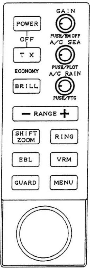
| GAIN | Adjusts receiver sensitivity. |
| push: HM OFF | 1. Temporarily erases the heading mark.2. Change + cursor data from R/B to L/L and vice versa. |
| A/C SEA | Suppresses sea clutter caused by waves. |
| push: PLOT | Turns on and off the radar target plotting circuit. |
| A/C RAIN | Suppresses rain clutter. |
| push: FTC | Suppresses heavy precipitation clutter. |
| POWER | Turns on the system. Press this touchpad and TX simultaneously to turn off the system. |
| TX | Sets the radar to transmit or stand-by. |
| ECONOMY | Lights (in green) to show the radar is in the "economy (stand-by)" mode. |
| BRILL | Adjusts the brightness of the screen. |
| RANGE | Selects radar range. The "+" and "-" touchpads select a higher and lower range, respectively. Selects items during the menu display. |
| SHIFT/ZOOM | Shifts the display; turns the zoom function on, and restores normal picture, in that order. |
| RING | Turns the fixed range rings on and off. |
| EBL | Turns the Electronic Bearing Line (EBL) on and off. |
| VRM | Turns the Variable Range Marker (VRM) on and off. |
| GUARD | Turns on and off the guard zone alarm. |
| MENU | Turns the menu display on and off. |
| Trackball | Controls the cursor, VRM, EBL, etc. |
Figure 2-1 Description of Front Panel Controls
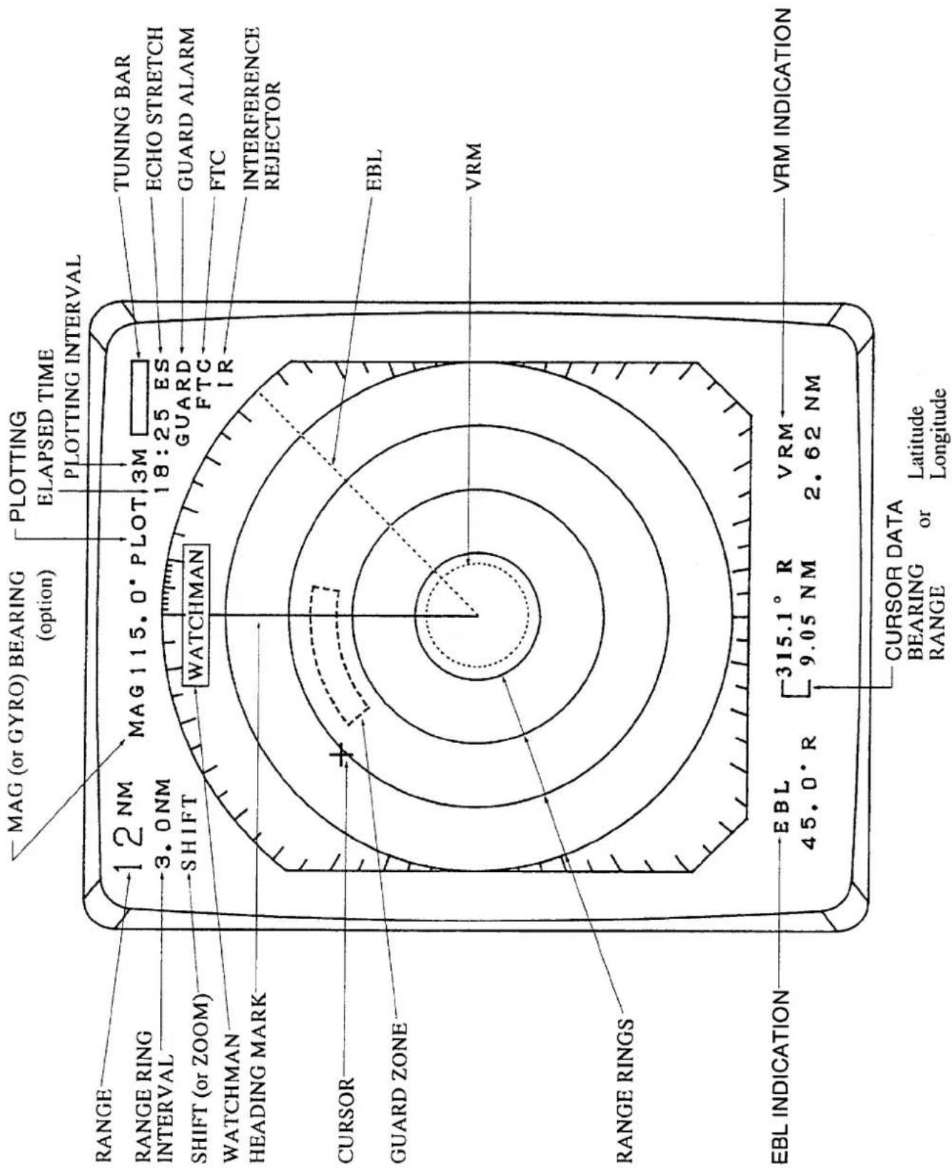
Figure 2-2 Display Screen Indications
Turning the Unit On and Off
After confirming there are no crew near the scanner unit, press the POWER touchpad to turn on the power.
The front panel will light up. The magnetron takes about two minutes and thirty seconds to warm up before the radar can be operated. The time remaining for warm up of the magnetron appears at the center of the display, counting down from 1:29 to 0:01.
To turn off the radar, press the POWER and TX touchpads together.
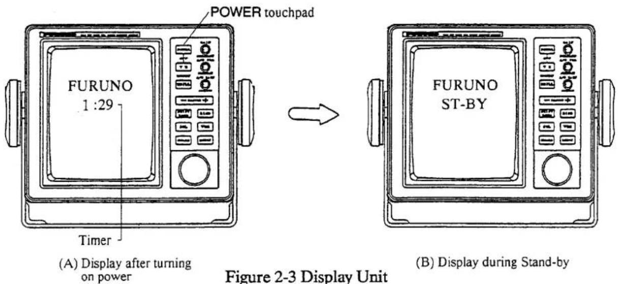
Figure 2-3 Display Unit
Basic Operation
After the power is turned on and the magnetron has warmed up, the message "ST-BY" (Stand-By) appears at the center of the display, showing the radar is ready to transmit. However, no targets will appear on the screen until the radar is transmitting by pressing the TX touchpad (TX is short for "transmit"). In stand-by the radar is available for use at anytime – but no radar waves are being transmitted.
Press the TX touchpad to begin transmission and to rotate the radiator. The display will light up, and the range in use, the range ring interval, the heading mark, the cursor, the range and bearing from own ship to the cursor intersection and the tuning bar appear. (Own ship's heading also appears if a magnetic compass or gyrocompass is connected.) When the radar is transmitting, any echoes from targets appear on the display.
If this is your first radar, you may want to take a closer look at the display. The outermost frame on the screen (marked in degrees) is the bearing scale. The solid radial line at 0 degrees is the heading mark. The heading mark is always on the screen and shows own ship's heading.
The nearly invisible line rotating radially around the screen is the "sweep." This lets the operator know that the radar is functioning properly. The sweep rotates synchronously with the scanner, so at any given time the direction in which the scanner is pointing is known. With every rotation echoes appear on the sweep as brighter spots of light, thus presenting a complete picture of the surrounding area.
Placing the radar in stand-by helps extend component life. Therefore, when you won't be using the radar for an extended period of time, but you want to keep it in a state of readiness, set it for the "ECONOMY" mode by pressing the TX touchpad. Power for the CRT is cut off after 2–3 seconds and the indication "ECONOMY" lights on the front pane to show that the "ECONOMY" mode is on.
Range selection
The range selected automatically determines the fixed range ring interval, the number of fixed range rings, pulselength, and pulse repetition rate, for optimal detection in short to long ranges. The range and ring interval appear at the top left corner of the display.
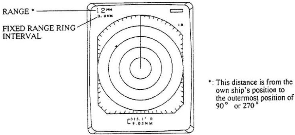
Figure 2-4 Location of Range and Fixed Range Ring Indications
To select a range, press the plus or minus sign on the RANGE touchpad. Note that it is possible to increase or decrease the range setting automatically by holding down these touchpads.
Tips on selecting range
1) When navigating in or around crowded harbors, select a short range to watch for possible collision situations.
2) If you select a lower range while on open water, increase the range occasionally to watch for vessels that may be heading your way. Remember that the maximum range a radar can see is dependent on many factors. For further details about maximum range, see the APPLICATION section.
Adjusting the GAIN control
The GAIN control adjusts the sensitivity of the receiver, and thus the strength of echoes as they appear on the screen. Adjust it so the speckled noise background is just visible on the display.
To become acquainted with the way the control works, try rotating it between its fully counterclockwise and clockwise positions as you observe the display. As you slowly turn the control clockwise you should be able to see the speckled background appear when the position of the control is between 2 and 3 o'clock.
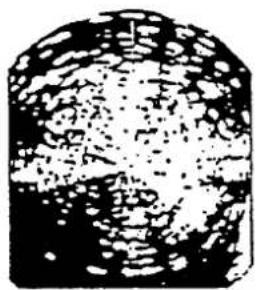
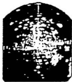
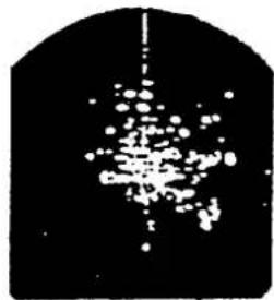
To properly set the gain, use the highest range—the background noise is clearer on this range. If you set up for too little gain, weak echoes may be missed. If you turn the control too far clockwise, yielding too much background noise, strong targets may be missed because of the poor contrast between desired echoes and the background noise on the display. Figure 2-5 illustrates examples of gain settings which are too high, proper, and too low.
natural_image
Abstract black-and-white textured pattern with no discernible text or symbols(A) Too high
natural_image
Abstract black-and-white pattern with a central vertical structure and scattered white dots (no text or symbols)(B) Proper
natural_image
Abstract black-and-white pattern with scattered white dots and a vertical line, no text or symbols present.(C) Too low
Figure 2-5 Adjusting the GAIN Control
Tips on adjusting GAIN
1) In certain circumstances it may be useful to reduce the gain slightly to improve range resolution, clear up the picture, or reduce clutter caused by rain or snow.
2) Range resolution is a measure of the capability of a radar to display as separate pips the echoes received from two targets which are on the same bearing, and are close together radially. With reduction in the gain setting, the echoes may be made to appear as separate pips on the display.
3) When sailing or cruising in crowded regions a slight reduction in gain often helps to clear up the picture. This should be done carefully, otherwise weak targets may be missed.
4) Echoes from ships inside a squall or storm may be obscured if the gain is at its normal setting, since the clutter may have masked, but not completely, echoes from the targets.
In all cases, return the gain to its original position after any temporary reduction is no longer required.
Adjusting the A/C SEA control
Echoes from waves can be troublesome, covering the central part of the display with random signals known as "sea clutter." The higher the waves, and the higher the scanner above the water, the further the clutter will extend. Sea clutter appears on the screen as many small echoes which might affect radar performance (see Figure 2-6 (A)). The A/C SEA control reduces the amplification of echoes at short ranges (where clutter is the greatest) and to progressively increase amplification as the range increases, so amplification will be normal at those ranges where there is no sea clutter. The control is effective up to about 4 miles.
The proper setting of the A/C SEA should be such that the clutter is broken up into small dots, and small targets become distinguishable.
If the control is not sufficiently advanced, other targets will be hidden in the clutter, while if it is set too high, sea clutter and targets will both disappear from the screen. In most cases turn the control clockwise until clutter has disappeared to leeward, but a little is still visible windward. Figure 2-6 illustrates how to adjust the control.
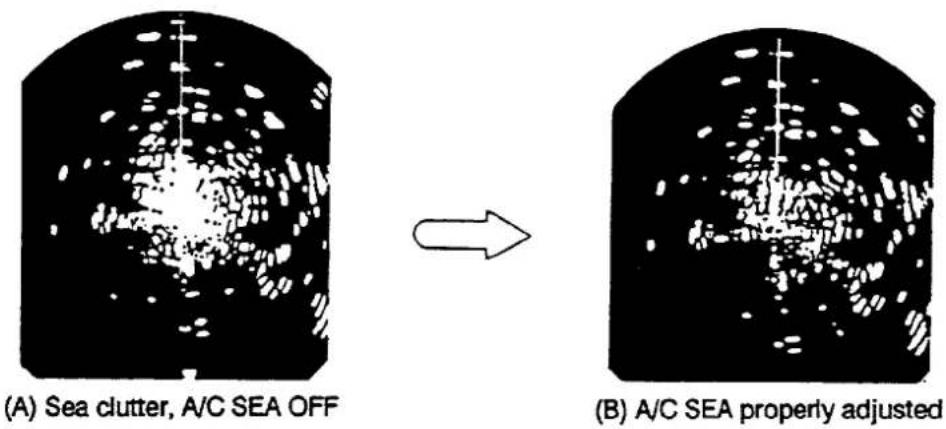
Figure 2-6 Adjusting the A/C SEA Control
Tips on adjusting A/C SEA
1) A common mistake is to over-adjust the control so all the clutter is removed. By rotating the control fully clockwise, you will see how the center of the screen becomes dark. This dark zone can be dangerous (targets may be missed), especially if the gain is not properly adjusted. Always leave a little clutter visible on the screen to be sure weak echoes will not be suppressed. If there is no clutter, leave the control in the fully counterclockwise position.
2) The GAIN is normally set to the point where there is a trace of noise speckles showing on the screen on a long range, and then adjust the A/C SEA control on a short range so you can see close-in targets in a harbor situation clearly. This equalizes the GAIN and A/C SEA characteristics for all ranges.
3) In moderate conditions on the open sea, where there are no definite targets on the shorter ranges, you should still adjust the GAIN on a long range for some noise speckles on the display, and then go down to a short range to adjust the A/C SEA until you can see a bit of sea clutter close to the boat.
Tuning the radar receiver
The radar receiver is tuned automatically each time you turn on the power, thus there is no front panel control for adjustment of the receiver. To show the automatic tuning circuit is working, a tuning bar displays tuning condition.
Adjusting display brightness
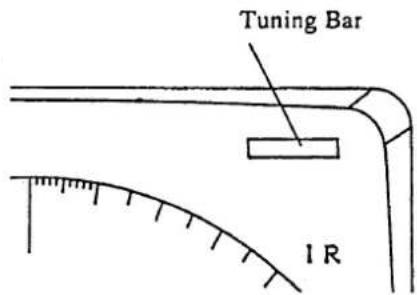
Figure 2-7 Location of Tuning Bar
The BRILL touchpad adjusts the brightness of the display in eight steps.
Adjusting front panel backlighting
Press the MENU touchpad and select "3. PANEL DIMMER" by the trackball. Then, select desired backlighting level with the RANGE touchpad. Refer to table 2-1 on page 2-9.
Erasing the heading mark
The heading mark continuously appears on the screen and shows ship's heading. When this mark obscures a target echo, you can temporarily erase it by pressing and holding the GAIN control.
Select the cursor data display
When connecting with NAV (NMEA0183 format) and gyro converter (NMEA0183 or AD-10 format), this radar can show the cursor position by Latitude/Longitude at bottom of screen.
Each time pressing [HM OFF] key, the data will change from Range/Bearing to Latitude/Longitude and vice versa.
With L/L position, this radar can output cursor position (TLL data) to a video plotter (position marked on the video plotter) by pressing the [HM OFF] key. When this is done the data display shows range and bearing instead of latitude and longitude.
The MENU Touchpad
The MENU touchpad displays the menu. Use the trackball for selecting menus, then select item with the RANGE touchpad. To erase the menu display, press the MENU touchpad again.
Note: Current selections shown in reverse video.
Figure 2-8 MENU Display
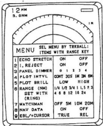
Table 2-1 Menu Description
| No. | Menu | Function | Factory setting |
| 1 | ECHO STRETCH | Activates and releases the echo stretch function, which stretches echoes lengthwise for better distinction. | OFF |
| 2 | INTERFERENCE REJECTION | Reduces or eliminates radar interference. | ON |
| 3 | PANEL DIMMER | Adjusts the backlighting of the front panel in five steps. | 3 |
| 4 | PLOT INTERVAL | Changes the plotting interval in five steps; 30 sec., 1 min., 3 min., 6 min. and continuous. | CONT |
| 5 | PLOT BRILLIANCE | Adjusts the brightness of the plotted echoes. | LOW |
| 6 | RANGE | Presets the ranges you want to use. The preset ranges are in reverse video.1. With the RANGE touchpad, place the underline under the range you want to select or deselect.2. Press the RING touchpad to select or deselect.Maximum number of ranges is all ranges.Minimum number of ranges is two. | 1/41/21248162436 |
| 7 | WATCHMAN | Turns on and selects the watchman interval.1. Select interval (5 min., 10 min., or 20 min.) with the RANGE touchpad.2. Press the MENU touchpad to activate the watchman mode. The "ECONOMY" indication lights after the radar transmits for about 30 seconds. | OFF |
| 8 | NAV DATA | Turns the navigation data display (navigation input required) on and off. | OFF |
| 9 | EBL/+CURSOR BEARING | Selects the bearing measured by the EBL or cursor in true (magnetic compass or gyrocompass connection required) or relative bearing."TRUE": relative to the True North"REL": relative to the bow of the vessel | REL |
Measuring Range and Bearing
In the basic radar system your ship is in the center of the screen, and any target received appears in a map-like projection throughout 360 degrees. This allows the bearing and range from your boat to a target appearing on the screen to be measured.
Range
You can measure the range to a target three ways: by the fixed range rings, the cursor, or the Variable Range Marker (VRM).
Fixed range rings
To get a rough measurement of the range to a target pip, use the fixed range rings, which are turned on and off by the RING touchpad. Count the number of rings between the center of the display and the target. Check the fixed range ring interval and judge the distance of the echo from the inner edge of the nearest ring. For example, the 12 nautical mile range scale has four fixed range rings, spaced three nautical miles apart. Therefore if a target is near the third ring from the center of the display, the range to the target would be about nine nautical miles.
Cursor/VRM
For more accurate measurement, use the cursor or the VRM.
To measure range by the cursor, operate the trackball to place the cursor intersection on the inside edge of the target echo. The range to the target appears at the bottom of the screen.
Now try measuring range with a VRM. Press the VRM touchpad to display a VRM. (The VRM is the dotted ring.) Place the VRM on the inside edge of the target by operating the trackball, and press the VRM touchpad again to fix the VRM to the position. Check the range readout to find the range to the target. To erase the VRM, press and hold down the VRM touchpad for about three seconds.
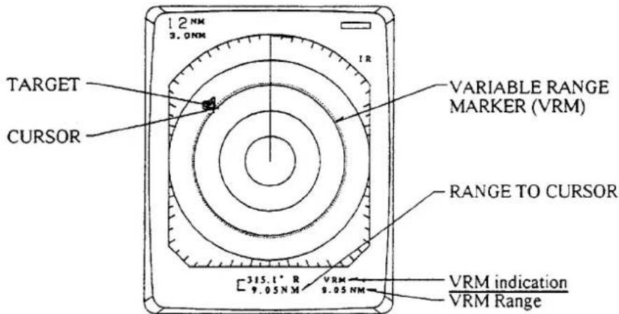
Figure 2-9 Measuring Range by the Cursor and the VRM
Note that the range to the cursor always varies with trackball operation. The VRM and its indication, however, are automatically fixed when the VRM touchpad is pressed, or 10 seconds elapses without trackball operation.
Unit of range measurement
You can display the range readouts of the VRM and the cursor in nautical miles or kilometers. This selection is done at installation. Refer to page 6-14.
Bearing
There are two ways to measure the bearing of a target: by the cursor or by the Electronic Bearing Line (EBL).
Cursor
For an estimate of the bearing to a target, operate the trackball to place the cursor intersection on the center of the target. The bearing to the target appears at the bottom of the screen.
EBL
Press the EBL touchpad to display an EBL. (The EBL is the dotted line.) Position the EBL so it bisects the target by operating the trackball, and press the EBL touchpad again to fix the EBL to the position. Check the bearing readout to find the bearing of the target.
To erase the EBL, press and hold down the EBL touchpad for about three seconds.
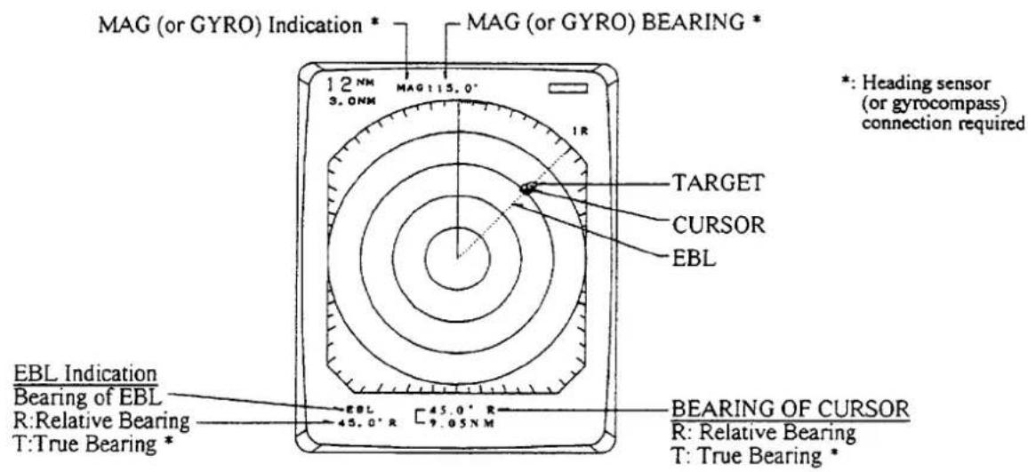
Figure 2-10 Measuring Bearing by the EBL and the Cursor
The bearing measured by the cursor or the EBL can be displayed in relative or true bearings (heading sensor or gyrocompass connection required). Relative bearings are relative to the bow of the vessel, and true bearings are relative to the True North. The indication "MAG" (or "GYRO") and the heading sensor (or gyrocompass) bearing (your ship's bearing) appear at the top of the screen. The indication method is selected at installation. Refer to page 6-14.
Note that the bearing to the cursor always varies with trackball operation. The EBL and its indication, however, are automatically fixed when the EBL touchpad is pressed or 10 seconds elapses without trackball operation.
Tips on measuring bearing
1) Bearing measurements of smaller targets pips are more accurate; the center of larger target pips is not as easily identified.
2) Bearings of stationary or slower moving targets are more accurate than bearings of faster moving targets.
3) To minimize bearing errors keep echoes in the outer half of the picture by changing the range scale; angular difference becomes difficult to resolve as a target approaches the center of the display.
Reducing Interference
Basically there are three types of interference which may hinder radar reception: sea clutter caused by echoes reflected of waves (mentioned earlier), precipitation clutter due to weather conditions, and radar interference from other shipborne radars operating nearby on the same frequency band. This radar can eliminate or reduce these types of interference.
Precipitation clutter
The vertical beamwidth of the scanner is designed to see surface targets even when the ship is rolling. However, by this design the unit will also detect rain storms, snow, or hail in the same manner as normal targets. Precipitation clutter is easily recognizable by its wool-like appearance on the display (see Figure 2-11). When this type of interference obscures a large area of the screen, you may use the FTC switch and/or the A/C RAIN control to eliminate or reduce the interference.
The FTC (Fast Time Constant) circuit works by splitting up these unwanted echoes into a speckled pattern, making recognition of solid targets easier. When only a slight amount of clutter is visible on the screen, turn the A/C RAIN control clockwise to distinguish targets from the clutter. In heavy storms or partial clutter, activate the FTC circuit by pressing the A/C RAIN control. Then, adjust the A/C RAIN control to reduce the clutter. "FTC" appears at the upper right-hand corner of the display when the FTC circuit is turned on.
In addition to reducing clutter, the FTC switch can be used in fine weather to clarify the picture when navigating in confined waters. However, with the circuit activated the receiver is less sensitive. Therefore, turn off the circuit when there is no clutter.
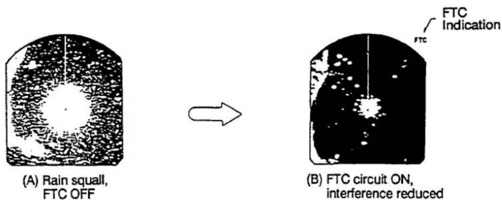
Figure 2-11 Effect of FTC
Radar interference
Radar interference may occur when near another shipborne radar operating in the same frequency band. Its on-screen appearance is many bright dots either scattered at random or in the form of dotted lines extending from the center (or the edge) to the edge (or the center) of the display. Figure 2-12 illustrates interference in the form of curved spokes. Interference effects are distinguishable from normal echoes because they do not appear in the same place on successive rotations of the scanner.
To reduce this type of interference, press the MENU touchpad and select "2. I.REJECT" by operating the trackball. Then, select "ON" by pressing the RANGE touchpad. (Factory setting is "ON".) The indication "IR" appears at the upper right-hand side of the screen. Press the MENU touchpad again to erase the menu display.
We recommend you to use the radar with "IR" turned on to maintain clear picture.
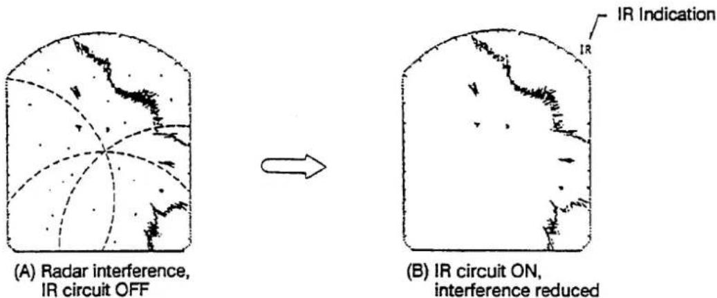
Figure 2-12 Effect of Radar Interference Rejection Circuit
Shifting and Zooming the Display
The SHIFT/ZOOM touchpad has two functions: display shifting and display zoom. Each time the touchpad is pressed the function changes in the following sequence.

flowchart
graph LR
    A["Normal"] --> B["Shift"] --> C["Zoom"]
Shift
The own ship's position can be shifted to any position within the current range. The primary advantage of the shifted display is that for any range setting, the view ahead of your own ship can be extended without changing the range.
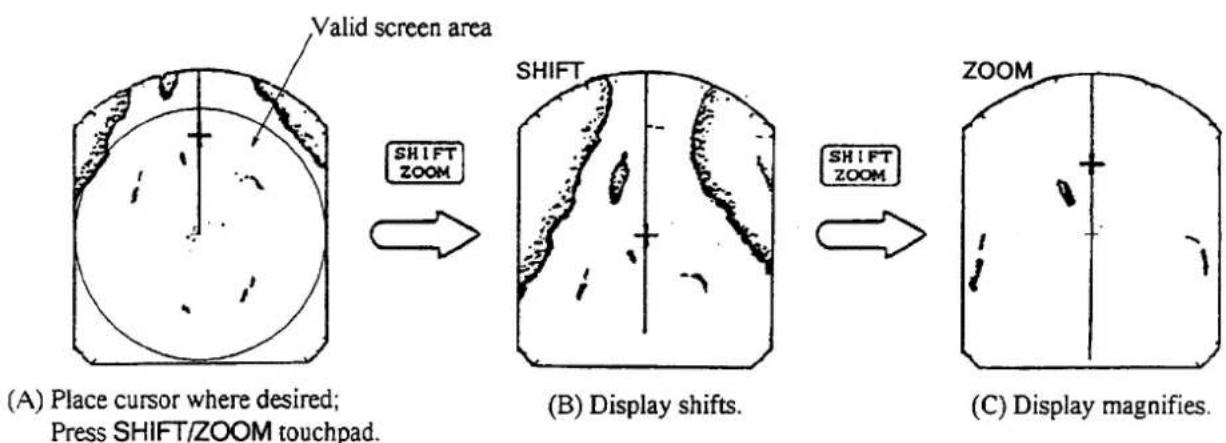
Place the cursor on area you wish to shift to the screen center and then press the SHIFT/ZOOM touchpad. The indication "SHIFT" appears. To restore normal operation press the touchpad twice.
NOTE: If the cursor is not within the current range when the touchpad is pressed, an audible beep sounds and the outermost range ring blinks twice, even if the range rings are off.
Zoom
The zoom feature allows you to double the area between own ship and an arbitrary location, to take a closer look at an area of interest without changing the range.
- Operate the trackball to place the cursor on the target you want or area you want to zoom.
- Press the SHIFT/ZOOM touchpad to display "ZOOM". The indication "ZOOM" appears and blinks.
- To turn off the zoom, press the touchpad again, or change the range.
flowchart
graph LR
    A["Place cursor where desired; Press SHIFT/ZOOM touchpad."] --> B["Valid screen area"]
    B --> C["SHIFT ZOOM"]
    C --> D["Display shifts."]
    D --> E["SHIFT ZOOM"]
    E --> F["Display magnifies."]
Figure 2-13 Shifting and Zooming the Display
Guard Alarm
The alarm allows the operator to set the desired range (0 to maximum range) and bearing (0 to 360 degrees) for a guard zone, called Auto In/Out Alarm. When ships, islands, landmasses, etc. go into (or go out of) the guard zone an audible alarm sounds to call the operator's attention. The alarm is very effective as an anti-collision aid when using an autopilot or navigating in narrow channels.
CAUTION
The alarm is a useful anti-collision aid, but does not relieve the operator of the responsibility to also keep a visual look-out for possible collision situations. The alarm should not be relied upon as the sole means for detecting possible collision situations. The 1972 Convention on the International Regulations For Preventing Collisions at Sea (1972 COLREGS) provides statutory requirements for the operation of any vessel, including the posting of lookouts. The operator of the vessel is responsible for compliance with those requirements whether or not a radar is in use.
Before setting the alarm, be sure the GAIN control is properly adjusted, because the audible alarm sounds when the fifth or more level quantization echoes go into or go out of the guard zone.
- Mentally create the guard zone you want to display on-screen. See Figure 2-14 (1).
- Set the upper (lower) left edge of the guard zone with the cursor. Press the GUARD touchpad. The indication "*GUARD" (asterisk blinking) appears at the upper right-hand side of the screen. See Figure 2-14 (2). The asterisk indicates the guard zone is partially set, but the alarm function has not been actuated. It disappears once the guard zone is set completely.
- Moving the trackball clockwise, set the lower (upper) right edge of the guard zone. The guard zone now appears on the display and the alarm function has been actuated. See Figure 2-14 (3).
NOTE: To create a 360 degree guard zone, rotate the cursor counterclockwise instead of clockwise. - Press the GUARD touchpad again. The asterisk disappears and the alarm function is actuated after three to five antenna scannings, and then, the indication "GUARD" is replaced by "G (IN)" or "G (OUT)".
- Any ships, landmasses, etc. coming into or going out (see page 2-18 for details) of the guard zone will trigger the audible alarm. If the audible alarm sounds you can silence it by pressing the GUARD touchpad. When this is done the indication "GUARD" appears in reverse video.
-
Press the GUARD touchpad again to restore the audible alarm. "GUARD" lights in normal video.
-
To cancel both the guard zone and the audible alarm, press and hold down the GUARD touchpad for three seconds.
Note 1: When the range is less than the half of the guard zone range, the guard zone disappears from the screen and "UP RANGE" indication appears. If this happens, select a range which will again display the guard zone on the screen.
Note 2: A target echo does not always mean a landmass, reef, ships or surface objects but can imply returns from sea surface or precipitation. As the level of these returns varies with environment, the operator should (properly) adjust the A/C SEA, A/C RAIN, FTC and GAIN to be sure target echoes within the guard zone are not overlooked by the alarm system.
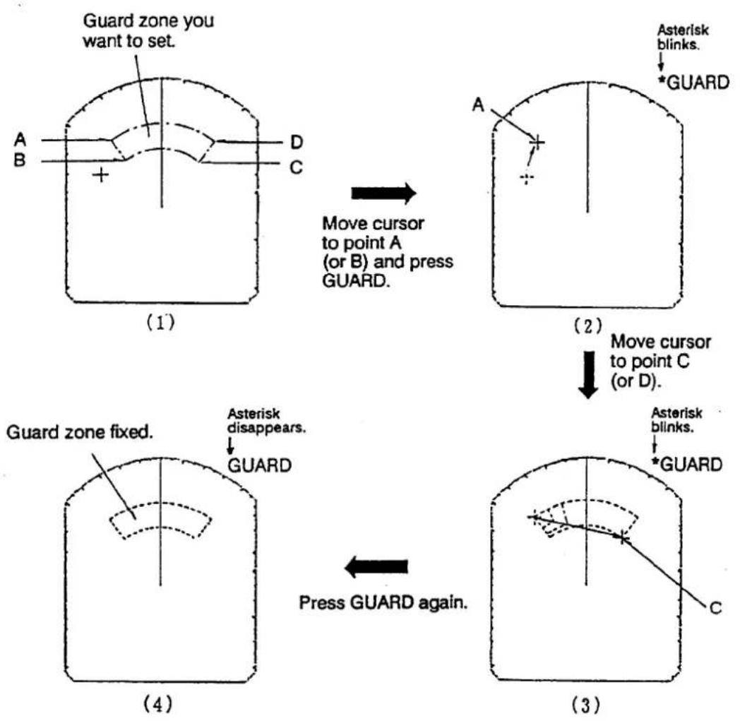
Figure 2-14 Setting Guard Zone
Auto In/Out Alarm
When the guard zone is set completely, the radar starts searching for targets inside the guard zone for 8 to 12 seconds. The indication "GUARD" appears during this period.
Case 1. When there are targets inside the zone, the alarm zone is automatically set to "Auto Out Alarm" mode and the indication "GUARD" is replaced by "G (OUT)". The audible alarm sounds only on targets which go out of the zone or disappear. See Figure 2-15 (1).
NOTE: The audible alarm does not sound for the target originally existing the zone.
Case 2. When no targets exist inside the zone, the alarm zone is automatically set to "Auto In Alarm" mode and the indication "GUARD" is replaced by "G (IN)". The audible alarm sounds only on targets which go into the zone. See Figure 2-15 (2).
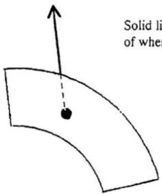
(1) G (OUT)
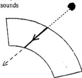
(2) G (IN)
Figure 2-15 Auto In/Out Alarm
Plotting
This function plots the movement of other ships relative to your own ship.
Press the PLOT switch to start plotting. The indication "PLOT" and a timer appear at the top right-hand corner of the screen and movement of all targets is plotted. The timer counts up from 0:01 to 99:59, whereupon the timer indication freezes but plotting continues. Targets initially are updated every 15 seconds. However, you can select intervals of 30 seconds, 1 minute, 3 minutes or 6 minutes thru the MENU display. Press the MENU touchpad and select "4. PLOT INTERVAL", referring to Table 2-1 on page 2-9. The plotting interval (except for 15 seconds) appears to the right of the indication PLOT.
If the range is changed during plotting, plotting begins anew with the newly selected range.
To cancel plotting, press the PLOT switch.
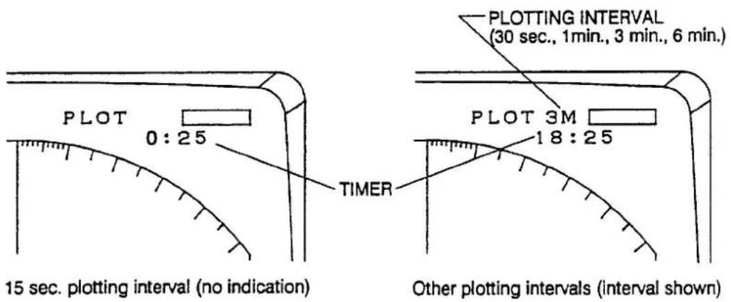
Figure 2-16 Plotting Indications
Plot Brilliance
The brilliance of plotted echoes is selectable thru the MENU display. Press the MENU touchpad and select "5. PLOT BRILLIANCE", referring to table 2-1 on page 2-9.
Better Distinction of Echoes
Normally, the reflected echoes from long distance targets appear on the screen as weaker and smaller blips even though they are compensated by the radar's internal circuitry. The Echo Stretch function magnifies these small blips in all ranges.
To turn on the echo stretch, press the MENU touchpad and select "1. ECHO STRETCH ON". The indication "ES" appears at the upper right-hand side of the screen and the echoes are doubled lengthwise.
To turn off the echo stretch, select "OFF" on the MENU display.
NOTE 1. This function magnifies not only targets but also sea clutter and radar interference. For this reason be sure the controls for adjustment of sea clutter and radar interference are properly adjusted before activating the echo stretch.
- This function is inactive on short ranges, that is 0.25 to 1 nautical miles. "ES" appears in reverse video when the echo stretch is turned on in those ranges.
WATCHMAN
The watchman function turns on the radar and transmits it for about 1 minute at a predetermined interval to check for targets in a guard zone. This feature is useful when you do not need the radar's function continuously but want to be alerted to radar targets in an area.
When the watchman feature is on, an internal timer turns on the radar every 5, 10 or 20 minutes and the radar transmits for 1 minute to check for the existence of radar targets in a guard zone.
- Determine the guard zone (usually 360 degrees) with the guard alarm function.
- Press the MENU touchpad and select "7. WATCHMAN" by the trackball. Select a transmission interval with the RANGE touchpads.
- Press the MENU touchpad again to actuate the watchman mode. The indication "WATCHMAN" appears and the radar transmits for one minute and then turns to stand-by, and "ECONOMY" lights.
- The radar automatically starts transmitting after the time selected at step 2 has passed. It transmits for one minute approximately and examines the guard zone for change.
4-1. If the condition is unchanged, the radar automatically returns to stand-by again and continues operating in the watchman mode.
4-2. If the condition differs from the previous one, the radar sounds an audible alarm, cancels the watchman mode and transmits continuously.
- To cancel the watchman mode manually, press any touchpad.
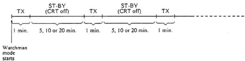
Figure 2-18 Watchman Mode
Note: The watchman function may be used without a guard zone. In this case, the beep tone sounds to call operator's attention whenever the radar starts transmitting. Press any touchpad to cancel the watchman mode.
3. APPLICATION
As an aid to navigation, radar can be a very valuable tool. No other navigation aid can give you the ability to spot vessels coming at you in the fog, or tell you the location of the inlet to the harbor in the pitch black of night. To help you understand better what your radar can and cannot do for you this section covers the characteristics and limitations of radar, picture interpretation, and position fixing with radar.
Factors Affecting Minimum Range
Targets disappearing from the screen when at close ranges can be dangerous. For this reason, detection of targets at short ranges is very important. Minimum range is determined primarily by transmitter pulselength. The shorter the transmission time, the sooner the return echoes can be received and their distance measured. This radar automatically determines the pulselength for both short and long ranges, for optimal detection of targets on all ranges.
Sea return
Sea clutter echoes received from waves may hamper detection of targets beyond the minimum range set by the pulselength and recovery time. (Recovery time is the time required for the receiver to recover to half sensitivity after the end of a transmitted pulse, so it can receive a return echo.) Proper adjustment of the A/C SEA control may alleviate some of the problem.
Vertical beamwidth
The ability to see targets very close to the boat is decreased if the antenna is mounted too high off the water, since the bottom of the vertical beam of the scanner cuts off nearby targets. Figure 3-1 illustrates the effects of a scanner mounted too high off the water.
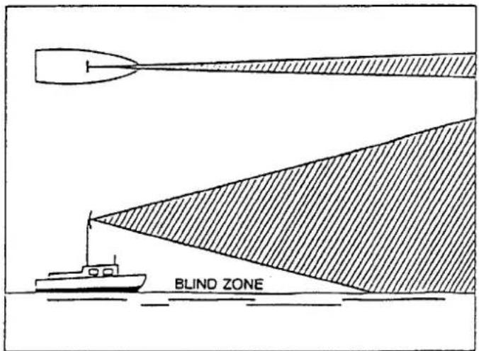
Figure 3-1 Effects of a Scanner Mounted too High off the Water
Factors Affecting Maximum Range
It is nearly impossible to state that a radar has a maximum range. The maximum range a radar will "see" is dependent on many factors, not just the range marked on the screen. Not only does the sensitivity of the receiver and power of the transmitter but also the height above the water of both the scanner and target, the size, shape and composition of the target, and atmospheric conditions contribute to increase or decrease the maximum detectable range.
Radar horizon
Radar is by its very nature essentially a "line-of-sight" phenomenon. That means that you have just about the same range to horizon with a radar as you do with your own eyes. However under normal atmospheric conditions, the radar horizon is 6% greater than the optical horizon. Therefore, if the target does not rise above the horizon the radar beam cannot be reflected from the target.
Just as you can see a low-to-the-water speedboat only up relatively close to your boat, the radar can see a target high off the water farther than it can see an object which is close to the water. Further, the higher the antenna is mounted over the water the farther it is capable of seeing other targets. However a possible negative effect with mounting the antenna too high off the water is that due to the finite vertical beamwidth of the scanner, the amount of sea clutter due to reflections from nearby waves is increased to a greater distance from the boat.
Thus it is not at all uncommon to see a 3000 foot high mountain 50 miles away (provided the radar has a 50 nautical mile detection capability), while at the same time being only able to see a small power boat 3 or 4 miles away. (See Figure 3-2.)
The distance to the horizon from the scanner, under normal conditions, is calculated by the following formula.
$$ \mathrm{Rmax} = 2. 2 \mathrm{x} (\sqrt {h 1} + \sqrt {h 2}) $$
Where Rmax: Radar horizon (mile), h1: Antenna height (meters), h2: Target height (meters)
For example, to find the distance to the horizon in Figure 3-2, if the antenna height is 8 meters (26 feet) and the target height is 15.2 meters (50 feet) the maximum range is (when the cliff begins to appear on the radar),
$$ \mathrm{Rmax} = 2. 2 \times (\sqrt {8} + \sqrt {1 5 . 2}) = 1 4. 8 \text {miles}. $$
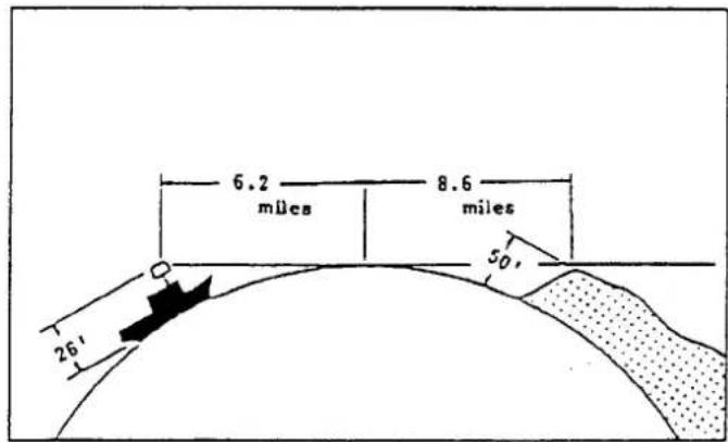
Figure 3-2 Radar Horizon
Target properties
Generally, larger targets can be seen on the radar display at greater ranges, provided line-of-sight exists between the scanner and target. However, a large target with poor reflecting properties may not be detected as easily as a smaller target with better reflecting properties.
Since one of the main functions of radar is to detect other ships, the composition of a target ships' hull affects the detection range. A ship whose hull is made of conducting materials, such as steel, will return a relatively strong echo.
On the other hand, hulls made from wood or fiberglass return much weaker echoes.
Vertical surfaces, such as a cliff, are good targets provided they face the radar. Conversely, horizontal and smooth surfaces such as mudbanks, sandy beaches, and gently sloping hills make poor targets because they disperse rather than reflect most of the energy that strikes them.
The strongest radar echoes known come from built-up areas, docks, etc., because these targets are less subject to changes in aspect. These types of targets have three flat, smooth surfaces mutually at right angles. Some radar buoys are arranged this way so as to deliberately increase their detection range.
Interpreting the Display
In the previous section some of the characteristics and limitations of radar were discussed. Now its time to take a look at what you can expect to see on the radar screen. What shows up on the screen isn't likely to match exactly what is seen on a navigation chart. A radar cannot see through a mountain in the path between your boat and the harbor, nor can it see a small boat directly behind a large ship, since both the mountain and the larger vessel effectively shield the radar from the desired target.
To aid you in target identification, the echoes appearing on the display are quantized in eight levels according to their intensity. The brightest intensity echoes are probably from steel ships, or piers, or other "good" targets. Poor targets, for example, wooden boats, appear in the weakest intensities.
The ability to interpret a radar picture comes through practice and experience. Practice should be done during clear weather in daytime, since you can compare the picture with what you actually see around you. Go to an area you are familiar with and compare the way coastlines, buoys and other targets appear on the screen and the way they are drawn on a navigation chart. To observe the movement of an echo in relation to your position, try running your boat at various speeds and headings.
Land targets
Landmasses are readily recognizable because of the generally steady brilliance of the relatively large areas painted on the display. Knowledge of the ship's navigational position will also tell you where land should be. On relative motion displays (this radar), landmasses move in directions and at rates opposite and equal to the actual motion of your own ship. Various factors such as distortion from beamwidth and pulselength make identification of specific features difficult. However, the following may serve as an aid to identification.
1) High, steep, rocky and barren landmasses provide good reflecting surfaces.
2) Low, vegetation covered lands make poor radar targets.
3) Submerged objects do not produce echoes.
4) Mud flats, marshes, sandspits, and smooth, clear beaches make poor targets because they have almost no area that can reflect energy back to the radar.
5) Smooth water surfaces such as lagoons and inland lakes appear as blank areas on the display—smooth water surfaces return no energy.
6) Although you might expect an object as large as a lighthouse to be a good radar target, in actuality the return echo is weak since the conical shape diffuses most of the radiated energy.
Ship targets
A bright, steady, clearly defined image appearing on the display is in all likelihood the target pip of a steel ship. There are several clues which can aid you in identification of a ship. Check your navigational position to rule out the possibility that a target pip is actually a landmass. Land and precipitation echoes are much more massive in appearance than the target pips of ships—which are relatively small. The rate of movement can eliminate the possibility that the pip is an aircraft.
A target pip may brighten and become dim due to changes in aspect and other factors. In most cases however a pip will fade from the display only when the range becomes too great.
Echo size
As the radar beam rotates, the appearance of a pip on the display screen will begin as soon as the leading edge of the radar beam strikes the target. The pip will continue to be seen on the display screen until the trailing edge of the beam rotates beyond the target. Thus, a target cannot appear less wide than the beamwidth. As the beam widens with distance from the scanner, so also will the widths of targets vary on the display. Figure 3-3 illustrates the relationship between beamwidth and the appearance of a target pip.
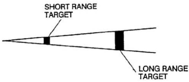
Figure 3-3 Beamwidth Versus Target Appearance
False Echoes
Occasionally false echoes appear on the screen at positions where there is no target. In some cases the effects can be reduced or eliminated. The operator should familiarize himself with the appearance and effects of these false echoes, so as not to confuse them with echoes from legitimate contacts.
Multiple echoes
Multiple echoes occur when a short range, strong echo is received from a ship, bridge, or breakwater. A second, a third or more echoes may be observed on the display at double, triple or other multiples of the actual range of the target as shown in Figure 3-4. Multiple reflection echoes can be reduced and often removed by decreasing the gain or properly adjusting the A/C SEA.
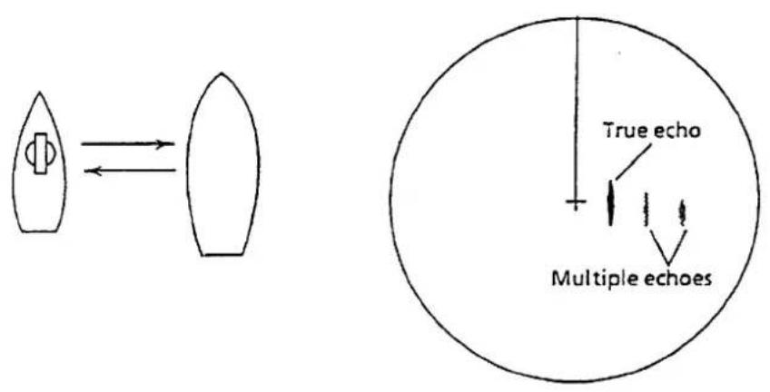
Figure 3-4 Multiple Echoes
Side-Lobe echoes
Every time the scanner rotates, some radiation escapes on each side of the beam—called "side-lobes." If a target exists where it can be detected by the side-lobes as well as the main lobe, the side echoes may be represented on both sides of the true echo at the same range, as shown in Figure 3-5. Side-lobes show usually only at short ranges and from strong targets. They can be reduced through careful reduction of the gain or proper adjustment of the A/C SEA control.
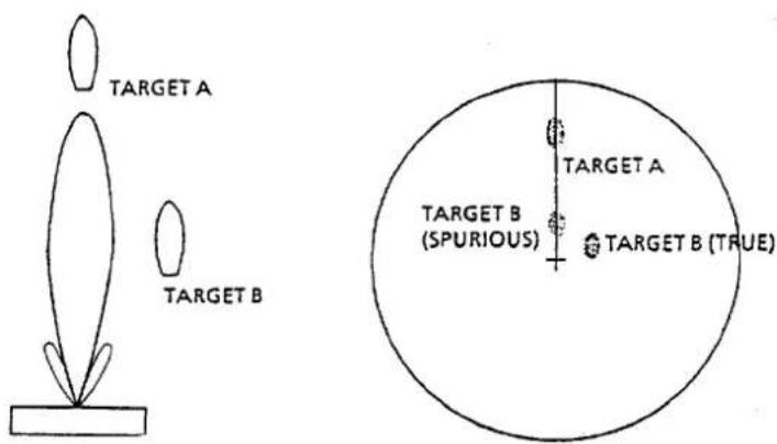
Figure 3-5 Side-Lobe Echoes
Blind and shadow sectors
Funnels, stacks, masts, or derricks in the path of antenna may reduce the intensity of the radar beam. If the angle subtended at the scanner is more than a few degrees a blind sector may be produced. Within the blind sector small targets at close range may not be detected while larger targets at much greater ranges may be detected. See Figure 3-6.
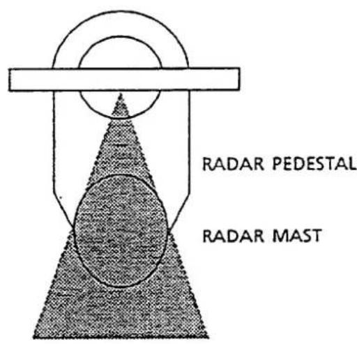
Figure 3-6 Blind and Shadow Sectors
Indirect echoes
Indirect echoes may be returned from either a passing ship or returned from a reflecting surface on your own ship, for example, a stack. In both cases, the echo will return from a legitimate contact to the antenna by the same indirect path. The echo will appear on the same bearing of the reflected surface, but at the same range as the direct echo. Figure 3-7 illustrates the effect of an indirect echo. Indirect echoes may be recognized as follows. (1) they usually occur in a shadow sector; (2) they appear on the bearing of the obstruction but at the range of the legitimate contact; (3) when plotted, their movements are usually abnormal, and (4) their shapes may indicate that they are not direct echoes.
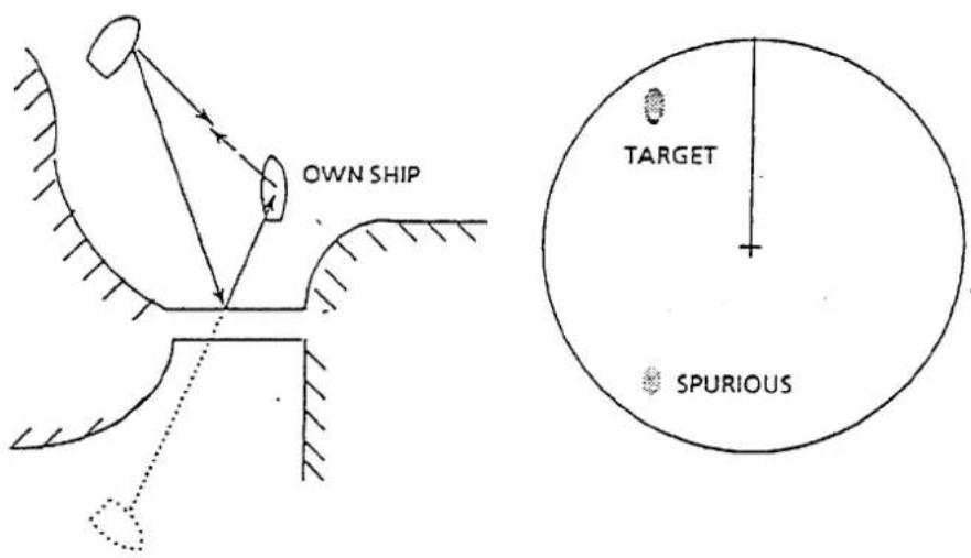
Figure 3-7 Indirect Echoes
Radar Picture and Corresponding Chart
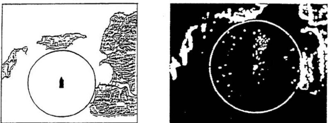
Under normal conditions, a picture which is very similar to a chart can be obtained on the radar display. The radar picture and corresponding chart shown in Figure 3-8 are from the Kada Inland Sea, south of Osaka Bay, in Southwestern Japan.
natural_image
Two abstract diagrams: one showing a circular region with a central arrow, the other depicting a starry night sky with scattered stars (no text or symbols)Figure 3-8 Navigation Chart and Corresponding Radar Picture
Position Fixing with Radar
Position fixing with radar can be accurately achieved once you become proficient in the different methods. The three most common methods will be discussed in this section. Take a compass and a navigation chart and try to fix your position while reviewing this section.
By radar range
The simultaneous measurement of the ranges to two or more fixed objects is normally the most accurate method of obtaining a fix with radar alone. Preferably at least three ranges should be used. However the use of more than three range arcs may introduce excessive error because of the time lag between measurements, namely, you will be moving as you take successive measurements.
When obtaining a fix, it is best to measure the most rapidly changing range last because of a smaller time lag in the radar plot from the ship's actual position. For greater accuracy, the objects selected should provide arcs with angles of cut as close to 90 degrees as possible. Small, isolated, radar-conspicuous fixed objects whose associated range arcs intersect at angles approaching 90 degrees provide the most reliable and accurate position fixes. Objects at longer ranges are less accurate for position fixing because they may be below the radar horizon and because the width of the radar beam increases with range.
To fix your position, first, measure the range to two or more prominent navigational marks which you can identify on the chart. Next, with the compass sweep out the ranges from the charted positions. The point of intersection of the arcs is your estimated position. The method of position fixing by radar range is illustrated in Figure 3-9.
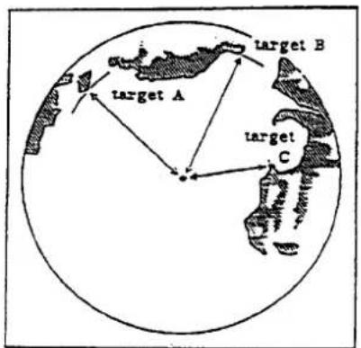
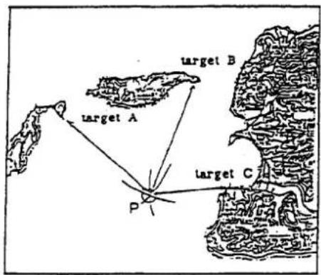
Figure 3-9 Position Fixing Using Radar Ranges
By range and bearing to a point of land
The advantage of position fixing by range and bearing to a point of land is the speed with which a fix can be obtained. A distinct disadvantage however is that this method is based upon only two intersecting position lines, a bearing line and range, obtained from two points of land. If possible, the object used should be small, isolated and identified with reasonable certainty. To fix your position using range and radar bearing, first, measure the relative
bearing of the target with the EBL, noting the exact direction of the ship's heading when doing so. Next, make allowance for compass deviation (true or magnetic) and find the true bearing of the target. Sweep out the range to the target with the compass on the chart and plot the true bearing of the target. The point of intersection is your approximate position. Figure 3-10 illustrates how to fix position by using a range and bearing to a point of land.
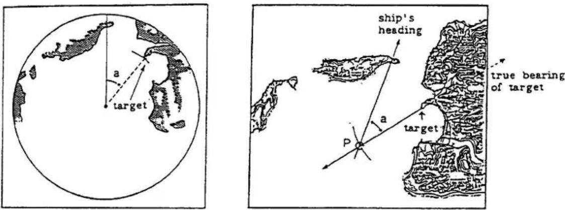
Figure 3-10 Position Fixing Using Range and Bearing to a Point of Land
By two bearings
Generally, fixes obtained from radar bearing are less accurate than those obtained from intersecting range arcs. The accuracy of fixing by this method is greater when the center bearings of small, isolated radar-conspicuous objects can be observed. Similar to position fixing using range and bearing, this method affords a quick means for initially determining approximate position. The position should then be checked against other means to confirm reliability.
Position fixing using two bearings is determined by measuring the relative bearings for the two targets and then determining their true bearings. Plot the two bearings on the chart; the point of intersection of the two bearings is your approximate position. Figure 3-11 illustrates the method of position fixing using two bearings.
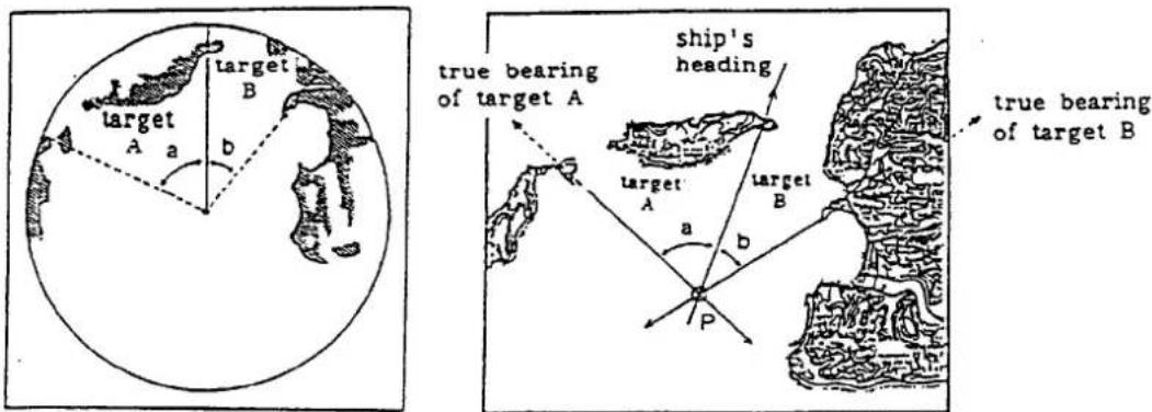
Figure 3-11 Position Fixing Using Two Bearings
Collision Avoidance and Relative Motion
CAUTION
The 1972 Convention on the International Regulations for Preventing Collisions at Sea (1972 COLREGS) provides statutory requirements for the operation of any vessel, including the posting of lookouts. The operator of the vessel is responsible for compliance with those requirements whether or not a radar is in use.
Collisions at sea sometimes occur because the radar picture doesn't match the information provided by the eye in clear weather and because of the misunderstanding of relative motion.
In a relative motion display, your ship is represented by the spot of light fixed at the center of the screen, regardless of the speed of your own ship. With both your own ship and the target in motion, the successive pips of the target do not indicate the actual or true movement of the target. If your own ship is in motion, the pips of fixed objects, such as land masses, move on the display at a rate equal to and in a direction opposite to the motion of your own ship. Only when your ship is stopped or motionless do target pips move on the display in accordance with their true motion. Figure 3-12 illustrates the relative and true motion of a target contacted by radar.
In Figure 3-12, ship A, at geographic position A1 on true course of 001° at 14 knots initially observes ship B on the PPI at bearing 179° at 4.1 nautical miles. The bearing and distance to the ship changes as ship A proceeds from position A1 to A3. The changes in the position of ship B relative ship A are illustrated in the successive PPI presentations corresponding to the geographic positions of ships A and B. Likewise, ship B at geographic position B1, on true course 25° at 21 knots initially observes ship A on bearing 001° at 4.1 nautical miles.
The radar operator aboard ship A will determine that relative movement of ship B is approximately 66.5 degrees, whereas the operator aboard ship B will determine that the relative movement of ship A is approximately 238 degrees. These figures were obtained using a maneuvering board.
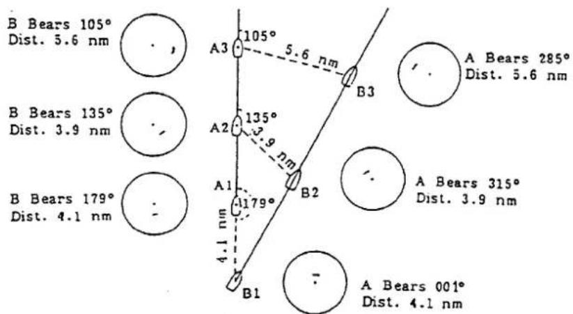
Figure 3-12 Radar Echo on Each Ship (North-up Relative Motion Mode)
Assessing the risk
The moment an echo appears on the screen its range and relative bearing should be measured and its true or magnetic bearing noted. This is best done on a chart or plot. Collision risk can be assessed only by carefully watching the true or magnetic bearing of an approaching vessel. If the bearing of the target does not appreciably change a possibility of collision may exist.
4. MAINTENANCE
General
Regular maintenance is important for good performance. Following the procedures prescribed in this chapter will help keep your unit in good working order for many years.
Always keep the equipment as free as possible from dirt, dust and water splashes. Make sure that all screws securing the components are properly tightened.
DANGER ELECTRICAL SHOCK HAZARD
This equipment uses high voltage electricity which can endanger human life. At several places in the unit there are high voltages sufficient to kill anyone coming in direct contact with them. While the equipment has been designed with consideration for the operator's safety, precautions must always be exercised when reaching inside the equipment for the purpose of maintenance and/or service. For this reason, only qualified personnel totally familiar with electrical circuits and service manual should work inside the display unit or scanner unit.
CAUTION: To prevent possible personal injury from radio frequency (rf) radiation hazards, make certain that no one is near the scanner before turning on the radar.
Scanner Unit
Radome
The radome surface should be kept free of dirt and salt deposits. A heavy deposit of dirt or caked-on salt on the radome will cause a considerable drop in radar performance. Clean the radome with a clean soft cloth. Do not use chemical cleaners except for alcohol. Also, check for cracks on the surface. If any cracks are found, they should be temporarily repaired by using a small amount of sealing compound or adhesive and the unit should then be brought to your local dealer for permanent repairs. A crack on the surface or deterioration of the rubber packing will cause permanent damage to the internal circuitry due to water leakage. Do not paint the radome.
Mounting base
Periodically confirm that the radome base and radome cover fixing bolts are secured tightly.
Display Unit
Cleaning the display screen
The face of the display screen will, in time, accumulate a coating of dust which tends to dim the picture. Clean lightly with a soft cloth, moistened with alcohol or cleaning fluid if desired. Do not use excess pressure; you may scratch the surface.
Fuse replacement
To protect the equipment from serious damage, a 10A (for 12VDC mains) or a 5A (for 24/32VDC mains) fuse is provided on the rear panel of the display unit. The fuse protects against overvoltage/reverse polarity of the ship's mains or internal fault of the equipment. If the fuse blows, first find the problem before replacing it with a new one. Never use a fuse rated for more than 10A or 5A, since it may cause serious damage to the equipment. OVER FUSING WILL VOID THE WARRANTY.
5. TROUBLESHOOTING
This section provides troubleshooting information for the user and the service technician. TO THE USER: If something appears to be wrong with your unit, check it by referring to the "Basic Troubleshooting" section. If you cannot restore normal operation, contact your Furuno dealer or qualified technician.
DANGER ELECTRICAL SHOCK HAZARD
This equipment uses high voltage electricity which can endanger human life. At several places in the unit there are high voltages sufficient to kill anyone coming in direct contact with them. While the equipment has been designed with consideration for the operator's safety, precautions must always be exercised when reaching inside the equipment for the purpose of maintenance and/or service. Only personnel totally familiar with electrical circuits and service manual should work inside the display unit or scanner unit.
TO THE SERVICE TECHNICIAN: Always make sure that the electrical power is turned off before attempting to change a component or inspecting the inside of the equipment. A residual charge may also exist in capacitors, even with the equipment turned off. Therefore, always short all supply lines to the chassis with an insulated screwdriver or a similar tool before touching the circuit.
WARNING: RADIO FREQUENCY (RF) RADIATION HAZARD
This radar scanner emits high frequency radio radiation which can be harmful, particularly to your eyes. Never look directly into the scanner from a distance of less than two feet when the radar is in operation as you could injure the cornea of your eyes. Always make sure that the radar is set to either Stand-By or OFF before starting work on the scanner.
Basic Troubleshooting
In most cases when the unit fails to operate properly the cause is very simple. Before calling for service or sending out the unit for repairs, check the following.
1) Nothing appears on screen. (Check that the front panel is illuminated. If it is not, check the following.)
If the power is cut off because the power protection circuit has actuated, press the POWER and TX/OFF touchpads together, then press the POWER touchpad.
- Is the battery dead?
- Is the fuse blown?
• Supply voltage is normal?
• Corroded battery terminals? - Poor contact of power cable?
2) No echo but numerical and character indications.
- Is the antenna plug loose?
3) Low sensitivity.
• Is the GAIN too low?
- Is the A/C SEA too high?
- Is the FTC ON?
• Is the brilliance too low?
- Is the radome dirty?
4) Noise on screen.
- Is the unit grounded?
5) Sweep not rotating.
• Is the antenna plug loose?
Advanced Troubleshooting
Advanced troubleshooting, replacement of defective parts and repair of this equipment involves exposure to high voltage capacitors which can cause severe personal injury or death. Only qualified personnel totally familiar with electrical circuits and service manual should work inside the display unit or scanner unit.
Before beginning work inside either unit, read the safety information at the beginning of this chapter.
Typical problems and their causes
1) Power cannot be turned on (panel does not light).
• Defective FIL Board.
- POWER SUPPLY Board. Measure voltage between J1301 #1(+) and #4(-) on the POWER SUPPLY Board. It should be 10.2 to 20.3 VDC for 12 VDC system, or 20.4 to 40.0 VDC for 24 and 32 VDC systems. See Figure 5-1 on page 5-5.
2) Power can be applied but nothing appears on the display.
- Check if the CRT heater is lit. If it is lit, the CRT is functioning normally.
- CRT high voltage.
- CRT SOCKET Board, MAIN Board. Adjust potentiometers R801 ("CONTRAST") on the CRT SOCKET Board and R404 ("BRIGHTNESS") on the MAIN Board.
• Defective SPU Board (SPU-9046).
3) Scanner does not rotate or rotates too fast/slow.
- Jammed scanner rotating mechanism.
• Defective scanner motor (B801).
• Defective motor control circuit.
4) Picture out of synch.
• Defective SPU Board (SPU-9046).
- MAIN Board of CRT assembly. On the MAIN Board, adjust potentiometer R510 ("V-HOLD") and coil L601 ("H-HOLD") for horizontal and vertical synchronization, respectively.
5) Sweep rotation is not synchronized with antenna rotation.
• Defective scanner motor (B801).
• Defective SPU Board (SPU-9046).
6) Marks and legends appear but no echo nor noise appear.
- Discontinuity or short circuit of video signal coaxial cable.
• Defective IF AMP Board(IF-9215).
• Defective SPU Board (SPU-9046).
7) Poor sensitivity.
- Deteriorated magnetron (V801). Refer to "Checking the Magnetron" (below).
• Detuned MIC (U801).
8) Noise, marks and indications appear but no echo.
• Defective SPU Board (SPU-9046).
• Discontinuity of trigger line.
• Defective MD Board (MD-9208).
- Magnetron heater voltage not applied. Refer to page 6-20.
- Defective magnetron (V801). Refer to next section.
Checking the Magnetron
Fewer echoes appear on the screen when the magnetron has deteriorated. To determine magnetron suitability, measure the magnetron current. For the location of parts, see Figures 5-2 and 5-3.
Note that "TOTAL ON TIME", the number of hours the radar has been operated, appears on the INSTALLATION menu. (See Figure 6-13(a) on page 6-11.) Roughly speaking, the life of the magnetron is approximately 3000 hours under normal usage.
- Connect a multimeter, set to 10 VDC range, to pins #5(+) and #6(-) of TP802 on the MD Board (MD-9208) in the scanner unit.
- Once turn off the radar system. Then, turn on DIP Switch S1 #4 on the SPU Board inside the display unit. Transmit the radar on short range.
- Confirm that the magnetron current (voltage) is 0.25 to 1.2 VDC.
- Change the range setting to long range and confirm that the voltage is 0.9 to 1.1 VDC.
- If the voltage is far out of the range specified above, the magnetron may be defective.
Be sure to turn off DIP Switch S1 #4.
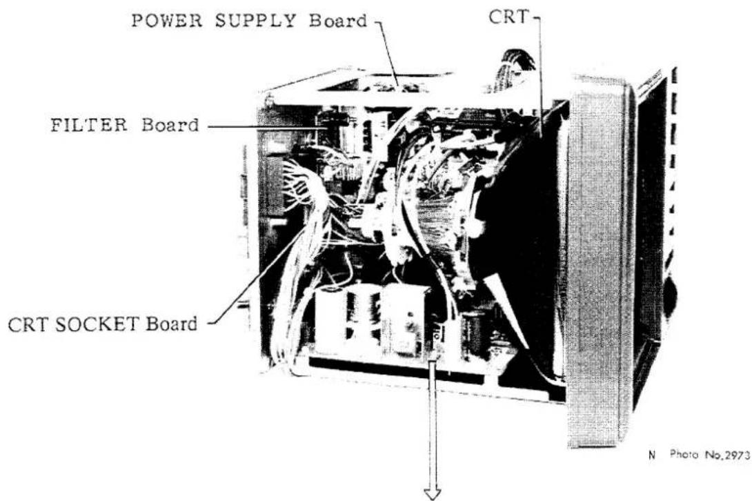
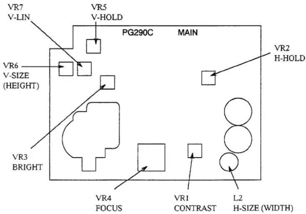
Note: Since the CRT is turned 90^ , the indications "V" and "H" correspond to "horizontal" and "vertical", respectively.
Figure 5-1 Display Unit Left Side View
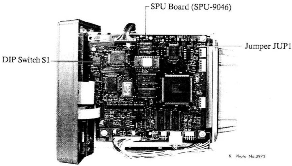
Figure 5-2 Display Unit Right Side View
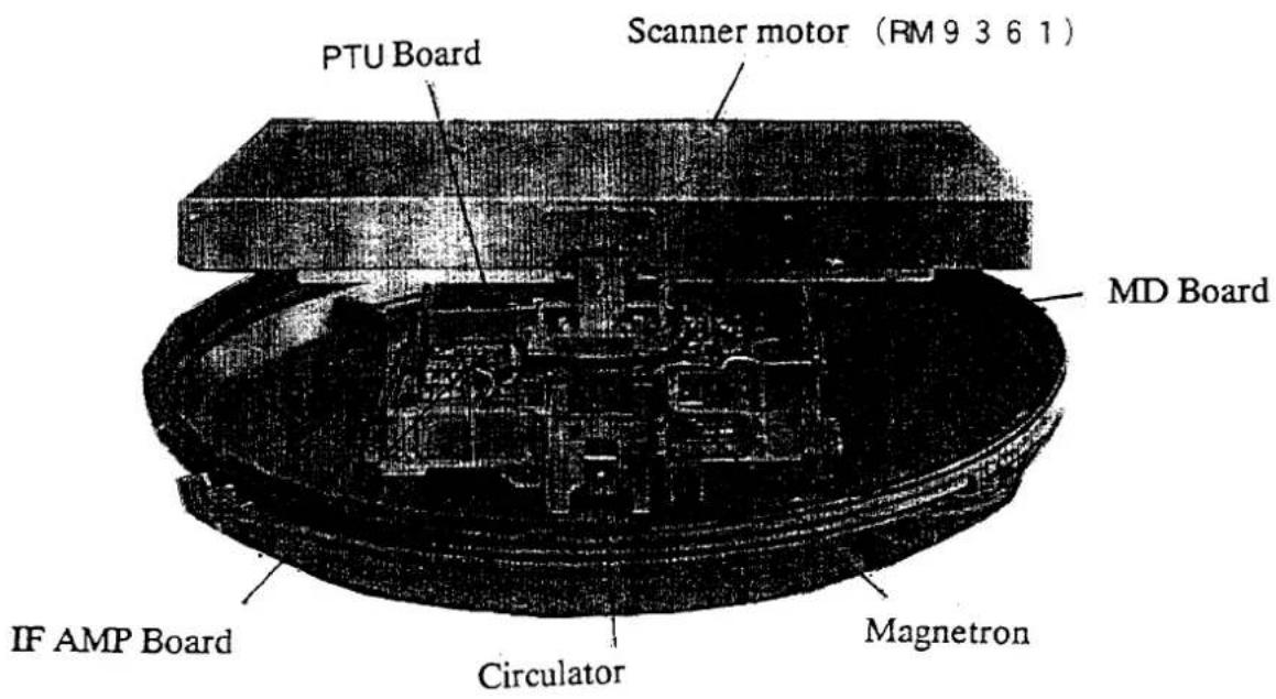
Figure 5-3 Scanner Unit with Cover Removed
6. INSTALLATION
This chapter provides the procedures necessary for installation. Installation mainly consists of the following:
- siting and mounting the display unit and antenna unit
- connection of the signal cable and the power cable
• establishing the ground - checking the installation, and
- adjustments.
Antenna Unit Installation
Siting, handling considerations
- The antenna unit is generally installed either on top of the wheelhouse or on the radar mast on a suitable platform. Locate the antenna unit where there is a good all-round view rigging intercepting the scanning beam. Any obstruction will cause shadow and blind sectors. A mast for instance, with a diameter considerably less than the width of the radicator, will cause only a small blind sector, but a horizontal spreader or crosstrees in the same horizontal plane as the antenna unit would be a much more serious obstruction; you would need to place the antenna unit well above or below it.
- It is rarely possible to place the antenna unit where a completely clear view in all direction is available. Thus, you should determine the angular width and relative bearing of any shadow sectors for their influence on the radar at the first opportunity after fitting. (The method of determining blind and shadow sectors appears later in this chapter.)
- If you have a radio direction finder on your boat, local its antenna clear of the antenna unit, to prevent interference to the direction finder. A separation of more than two meters is recommended.
- To lessen the chance of picking up electrical interference, avoid where possible routing the signal cable near other onboard electrical equipment. Also avoid running the cable in parallel with power cables.
- The compass safe distance should be observed to prevent deviation of the magnetic compass.
| Standard compass | Steering compass |
| 0.9 m | 0.7 m |
- Do not paint the radome, to ensure proper emission of the radar waves.
- When this radar is to be installed on larger vessels, consider the following points:
(1) This signal cable run between the antenna and the display comes in lengths of 10 m, 15 m, 20 m and 30 m, whatever length is used it must be unbroken; namely, no splicing allowed.
(2) Deposits and fumes from a funnel or other exhaust vent can adversely affect the aerial performance and hot gases may distort the radiator portion. The antenna unit must not be mounted where the temperature is more than 70^ C
Mounting the antenna
-
Open the antenna unit packing box carefully.
-
Unbolt the four bolts at the base of the radome to remove the radome cover.
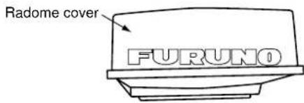
Antenna unit
The mounting surface must be parallel with the waterline and provided with five holes whose dimensions are shown in the outline drawing attached at the end of this manual.
The unit is adjusted so a target echo returned from the bow direction will be shown on the zero degree (heading line) position on the screen. When drilling holes, be sure they are parallel with the fore and aft line.
- Prepare a platform of 5 to 10 millimeters in thickness for the antenna unit.
A mounting bracket for mounting the antenna unit on a sailboat mast is optionally available. (Refer to page 1-9.) Find the cable entry on the radome base. Next, position the radome base so the cable entry faces the stern direction. This alignment must be as accurate as possible.
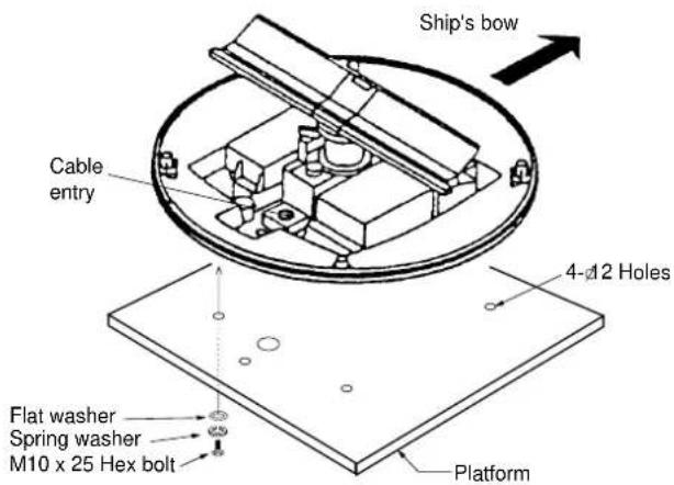
Antenna unit, cover removed Antenna unit
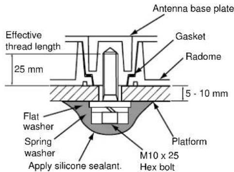
How to fasten the radome base to the mounting platform
Wiring and final preparation
- Drill a hole of at least 20 millimeters diameter through the deck or bulkhead to run the signal cable between the antenna unit and the display unit. (To prevent electrical interference avoid running the signal cable near other electrical equipment and in parallel with power cables.) Pass the cable through the hole. Then, seal the hole with sealing compound for waterproofing.
- Remove two shield covers in the radome.
- Remove the cable clamping plate by unfastening four screws and removing a gasket.
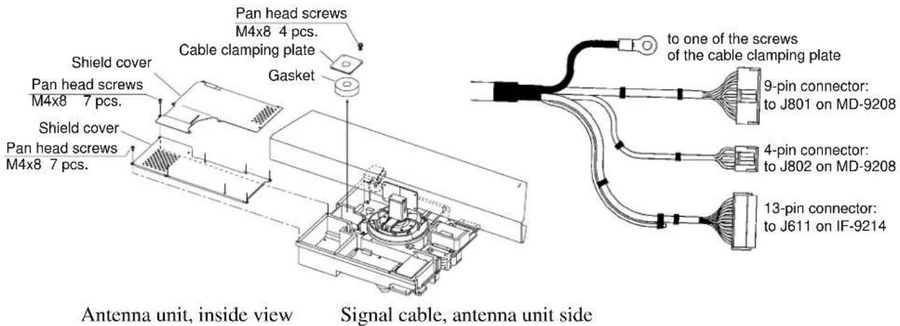
- Pass the cable through the hole at the bottom of the radome base.
- Secure the cable with the cable clamping plate and gasket. Ground the shield and vinyl wire by one of the screws of the cable clamping plate.
- Connect the wire to the RF unit.
- Attach the EMC core supplied as shown below.
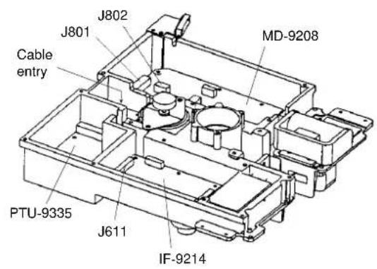
RF unit
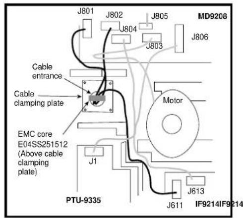
How to attach EMC core
- Fix the shield cover. Do not pinch the cable.
- Attach the radome cover, aligning triangle mark on radome cover with that on radome base.
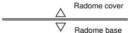
How to position the radome cover
- Loosely fasten the radome fixing bolts. You will tighten them after confirming magnetron heater voltage.
Display Unit Installation
Locate the display unit in a position where it can be viewed and operated conveniently but where there is no danger of salt or fresh water spray or immersion.
Compass Safe Distance; The magnetic compass may be affected if the display unit is placed too close, because of fields generated in the radar. The compass safe distance (approximately 0.5m (1.64 feet) standard compass and approximately 0.4m (1.31 feet) steering compass) must not be disregarded.
The orientation of the display unit should be so that the radar screen is viewed while the operator is facing in the direction of the bow. This makes determination of your position much easier.
The display unit is mounted in a trunnion mount. The mount itself can be installed either overhead, on a bulkhead, or on a tabletop. The drawing below gives the recommended clearances and the mounting dimensions for this unit. You can use the mount itself as a template for locating the mounting screw holes. Although the unit is lightweight (4.8 kilograms), reinforce the mounting place, if necessary.
The mounting procedure is:
- Mark the screw locations by using the trunnion as a template.
- Drill five pilot holes for the trunnion.
- Install the trunnion using the screws supplied as the installation materials.
- Fit the knob bolts and washers to the display unit.
- Install the display unit in the trunnion. Tighten the knob bolts securely.
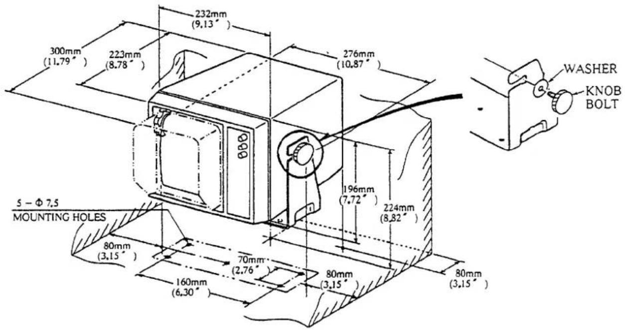
Figure 6-6 Display Unit Outline Drawing
Make sure you allow enough clearance both to get to the connectors behind the unit and to allow you to get your hands in on both sides to loosen or tighten the mounting knobs. Make sure you leave at least a foot or so of "service loop" of cables behind the unit so that it can be pulled forward for servicing or easy removal of the connectors.
Installation of rubber vibration isolators
The rubber vibration isolators stabilize the display unit against ship's vibration. Attach them to the mounting bracket if necessary as follows.
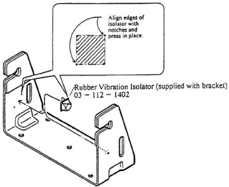
Figure 6-7 Rubber Vibration Isolator
Now comes the wiring part. For general wiring diagram, see page 6-8.
Antenna connection
Connect the interconnection (multicore) cable from the scanner unit at the back of the display unit.
Power connection
This radar is designed for 12, 24 or 32 volt battery systems. No internal wiring changes are needed for input voltage from 10.2 to 40.0 VDC. A piece of gear of this quality deserves to have a circuit breaker dedicated to it alone.
The power cable is fitted with a connector at one end. Pass the other end of the cable through the rubber socket cap (supplied) for waterproofing. Connect the cable to the display unit, then cover the connector with the socket cap.
Ground connection
Run heavy duty ground wire from the ground terminal at the rear panel of the display unit to the nearest grounding point on the boat. Consult with a qualified electrician if you are uncertain of where the proper grounding points on your vessel are.
Gyrocompass (or heading sensor) connection (option)
If an AC synchro or DC step type gyrocompass is installed on your boat, the true bearing of your ship's heading, of the cursor, and of the EBL (Electronic Bearing Line) may be displayed on the display.
You will need the following cable and A-D Converter AD-100 (both optionally supplied) to make the connection.
- Cable Assy 22S0269-0 for connecting the display unit to the AD-100
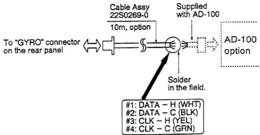
flowchart
graph TD
    A["To "GYRO" connector on the rear panel"] --> B["Cable Assy 22S0269-0 10m, option"]
    B --> C["Solder in the field."]
    C --> D["Supplied with AD-100"]
    D --> E["AD-100 option"]
    F["#1: DATA - H (WHT)"]
    G["#2: DATA - C (BLK)"]
    H["#3: CLK - H (YEL)"]
    I["#4: CLK - C (GRN)"]
Figure 6-8 Gyro Connection
Follow the steps below to connect the gyrocompass.
- Remove the connector cap from the "GYRO" connection location on the rear panel.
- Solder the end of the Cable Assy to the cable supplied with the A-D Converter. Refer to the operator's manual for the AD-100.
- Connect the other end of the Cable Assy to the connector exposed in step 1.
- Press and hold the MENU touchpad for 10 seconds to display the INSTALLATION menu. Select "3. MAG/GYRO" by the trackball. Then, select "GYRO" with the RANGE touchpad.
- Press the MENU touchpad again and the indication "GYRO" appears at the top of the screen.
The heading sensor (FLUX-50, C-2000) having AD-10S format or NMEA 0183 output data format can be connected instead of a gyrocompass. In this case, you should select "MAG" instead of "GYRO" on the INSTALLATION menu.
When heading data of NMEA0183 format is used, connect the signal to "GYRO" connector J353#1(DATA-H) and #2(DATA-C). The acceptable data (talker/sentence) are **HDM, **HDG and **HDT.
External navigational receiver connection (option)
If your navigational receiver has NMEA 0183 or FURUNO CIF data format, your own ship's position in latitude/longitude, the range/bearing to waypoint, ship's speed, heading and course may be input to this radar, and be seen in the bottom text area.
You will need the following cable (optionally supplied) to make the connection.
| Type | Code no. | Remarks |
| MJ-A6SPF0012-050 | 000-134-424 | 5 m |
| MJ-A6SPF0012-100 | 000-133-817 | 10 m |
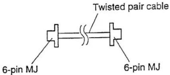
Figure 6-9 Navigational Receiver Connection
Fuse exchange for 24/32VDC power supplies
The display unit is shipped with a 10A fuse (F1351) fitted in the fuse holder on the rear panel. This fuse is for use with 12VDC power supply. For 24VDC or 32VDC power supplies, please exchange the fuse with the 5A fuse supplied.
The figure below gives detailed wiring information.
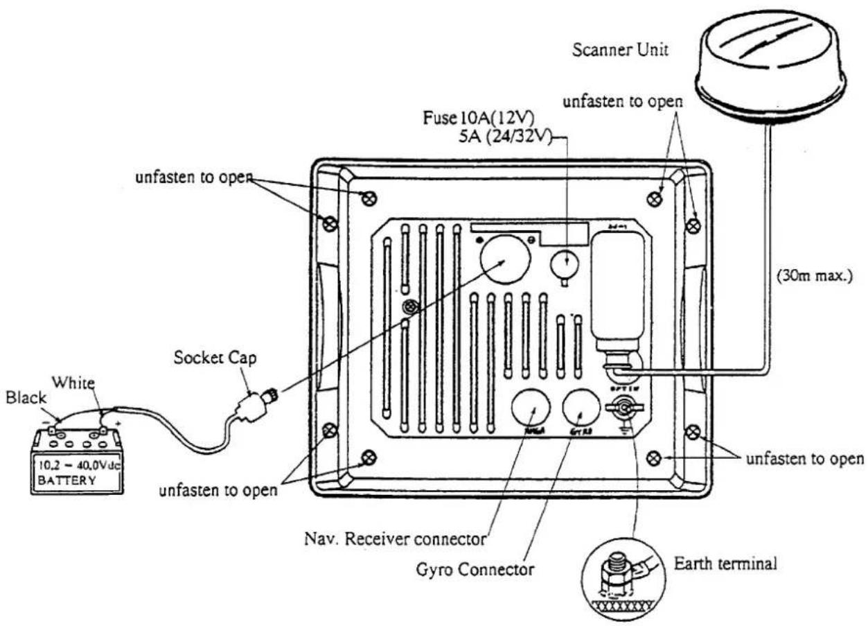
Figure 6-10 Detailed Wiring Diagram
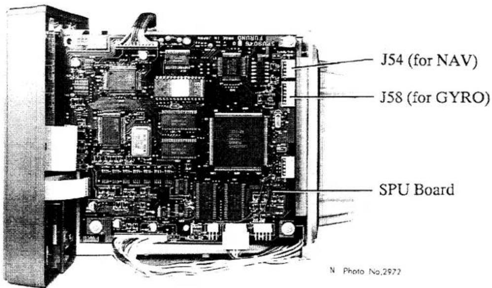
Figure 6-11 Right-side View of Display Unit
Checking the Installation
After installing the unit check it for proper installation by using the checklist below.
Table 6-1 Installation Checklist
Tick here.
☐ Four radome fixing bolts are fully tightened.
☐ The connection cable is waterproofed at the radome base.
☐ The cable is securely retained against the mast or mounting and is free of interference from running rigging.
☐ Check that the cable gland or entry on the deck is waterproofed, if provided.
☐ The power connections to the battery are of correct polarity.
☐ Check that the plugs at the rear of the display are inserted correctly and are secure.
☐ Check that fuse F1351 on the rear panel is 10A (for 12VDC) or 5A (for 24/32VDC). If the input voltage is changed from 12VDC to 24/32VDC in the field, change the fuse.
Adjustments
After checking the unit for proper installation its time to adjust it.
To prevent possible personnel injury from radio frequency (rf) radiation hazards, be certain that no one is near the scanner before turning on the radar.
Tuning and calibration of this equipment requires experience and specific technical skills. Thus this work should be performed by a qualified service technician.
Initial procedures
- Press the POWER touchpad on the display unit, and the front panel will light up. In approximately two minutes and 30 seconds, the message "ST-BY" will appear at center of the screen. While this warmup is in process, set the GAIN control at 2 o'clock, and the A/C RAIN and A/C SEA controls at fully counterclockwise.
- When "ST-BY" appears press the TX touchpad. The radar will start transmitting, and you will probably see some targets around you, even though the adjustments have yet to be optimized.
- Bring up the GAIN control until a small amount of noise appears on the screen.
- Adjust the GAIN control on the front panel, for a little background noise showing on the screen, and then hit the RANGE - touchpad several times to bring you down to the minimum range. Without disturbing the front panel GAIN control, adjust the A/C SEA control until nearby radar targets are clearly shown on the screen. Too much A/C SEA action will eliminate small targets, and too little A/C SEA action will cause the screen to be so full of targets and noise that it is hard to determine which target is which as compared to visual sightings. Note that adjusting the GAIN and A/C SEA controls in this manner (GAIN at long range, A/C SEA at short range) will equalize the picture at all ranges, and you will not have to jockey back and forth with the GAIN control especially when you change range scales.
Sweep timing
This adjustment ensures proper radar performance, especially on short ranges. The radar measures the time required for a transmitted echo to travel to the target and return to the source. The received echo appears on the CRT based on this time. Thus, at the instant the transmitter is fired, the "Sweep" should start from the center of the CRT (sometimes called sweep origin.)
A "trigger" pulse generated in the display unit goes to the scanner unit through the interconnection cable to trigger the transmitter (magnetron). The time taken by the signal to travel up to the scanner unit varies, depending largely on the length of interconnection cable. During this period the display unit should wait before starting the sweep. When the display unit is not adjusted correctly, the echoes from a straight local object (for example, a harbor wall or straight pier) will not appear with straight edges—namely, they will be seen as "pushed out" or "pulled in" near the picture center. The range of objects will also be incorrectly shown.
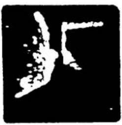
natural_image
Abstract black-and-white graphic with no discernible text, symbols, or structured content.(A) Improper, pulling inward
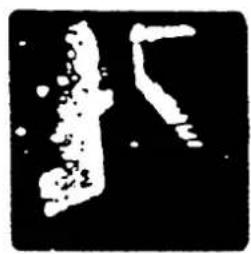
natural_image
Abstract black-and-white graphic with two stylized human-like shapes (no text or symbols)(B) Proper

natural_image
Abstract black-and-white graphic with a central circular shape and curved lines (no text or symbols)(C) Improper, pushing outward
Figure 6-12 Examples of Improper and Correct Sweep Timings
- Transmit the radar on the shortest range and adjust the GAIN and A/C SEA controls.
- Visually select a straight echo (harbor wall, straight pier).
- Press and hold down the MENU touchpad (about 10 seconds) until the INSTALLATION menu appears.
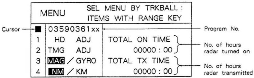
Figure 6-13(a) INSTALLATION Menu
- With the trackball, select "2. TMG ADJ".
| MENU SEL MENU BY TRKBALL : ITEMS WITH RANGE KEY | ||
| 1 | HD ADJ | DSPL STR TGT |
| 2 | TMG ADJ | ON SHORT RNG. |
| 3 | MAG / GYRO | PRESS -/+ KEY |
| 4 | NM / KM | TO STRAIGHTEN. |
Figure 6-13(b) Timing Adjustment
- While looking at the target selected at step 2, press the RANGE + touchpad if the target is pulled inward, or press the RANGE - touchpad if the target is pushed outward.
- Press the MENU touchpad to complete the adjustment.
Relative bearing alignment
You have mounted the scanner unit facing straight ahead in the direction of the bow. Therefore, a small but conspicuous target dead ahead visually should appear on the heading mark (Zero degree).
In practice, you will probably observe some small error on the display for most installations because of the difficulty in achieving accurate initial positioning of the scanner unit. The following adjustment will compensate for this error.
If you don't know how to do it well, it's best you leave this part to a qualified technician. (Remember that the scanner housing fixing bolts remain untightened. They should now be secured if the following alignment is not necessary.)
- Identify a suitable target (for example, ship or buoy) at a range between 1/8 to 1/4 miles, preferably near the heading mark. To minimize error, keep echoes in the outer half of the picture by changing the range.
- Measure the bearing to the target by operating the trackball. The bearing is shown at the bottom center of the screen.
- Using a compass card, visually find the relative bearing to the target.
- Compare the bearing measured in step 2 and 3 above and calculate the direction and magnitude of the bearing error. If the error is within 30 degrees go to step 9, to correct the error at the display unit. If the error is greater than 30 degrees first make initial adjustments at the scanner unit and then fine tune at the display unit.
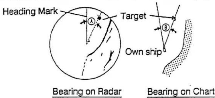
Figure 6-14 Calculating Bearing Error
-
Open the radome cover and slightly loosen the two screws which secure the heading mark key mounting plate. Overloosening makes fine adjustment difficult.
-
Adjust the position of the heading mark key, moving to the aft (or fore) direction if the bearing A is greater (or smaller) than bearing B, respectively. Note that it is necessary to correct the error only so it is within 30 degrees.
-
Tighten the fixing screws.
-
Close the radome cover on the radome base assembly, being careful of its direction. The narrower recessed part should face the bow direction. See Figure 6-8.
-
Press and hold down the MENU touchpad (about 10 seconds) until the INSTALLATION menu (Figure 6-16) appears.
-
With the trackball, select "1. HD ADJ". The heading marker and tuning range markers appear. See Figure 6-20(a).
-
Identify a suitable target (for example, ship or buoy) at a range between 1/8 to 1/4 miles, preferably near the heading mark. To minimize error, keep echoes in the outer half of the picture by changing the range.
-
Press a RANGE touchpad to bisect the target with the heading marker. See Figure 6-20(b).
-
Press the MENU touchpad or select other menu by the trackball to complete the adjustment.
-
As a final test, move the boat towards a small buoy and confirm that the buoy shows up dead ahead on the radar when it is visually dead ahead.
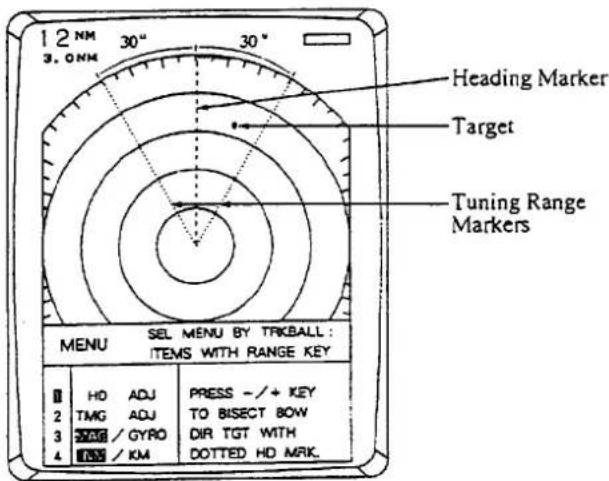
(a)
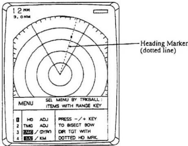
(b)
Figure 6-15
Display During Heading Adjustment
MAG or GYRO indication
When a gyrocompass or heading sensor is connected to this radar, select it on the INSTALLATION menu.
- Select "3. MAG/GYRO" on the INSTALLATION menu.
| MENU SEL MENU BY TRKBALL:ITEMS WITH RANGE KEY | ||
| 1 | HD ADJ | SEL “MAG” FOR |
| 2 | TMG ADJ | MAG COMPASS, |
| 3 | MAG / GYRO | “GYRO” FOR |
| 4 | NM / KM | GYROCOMPASS. |
Figure 6-16 MAG/GYRO Selection
-
Select "MAG" (factory setting) or "GYRO" with the RANGE touchpad.
-
Press the MENU touchpad to complete the setting.
Range unit selection
The range unit of the cursor and the VRM is selectable for either "NM" (nautical mile) or "KM" (kilometer).
- Select "4. NM/KM" on the INSTALLATION menu.
| MENU SEL MENU BY TRKBALL:ITEMS WITH RANGE KEY | ||
| 1 | HD ADJ | RANGE UNIT; |
| 2 | TMG ADJ | NAUTICAL MILE |
| 3 | MAG / GYRO | OR KILOMETER. |
| 4 | NM / KM | |
Figure 6-17 NM/KM Selection
-
Select "NM" (factory setting) or "KM" with the RANGE touchpad.
-
Press the MENU touchpad to complete the setting.
Magnetron heater voltage
Magnetron heater voltage is formed at the MD Board of the scanner unit and preadjusted at the factory for use with any length of interconnection cable. Therefore no adjustment is required. However, verify heater voltage by the following.
- Connect a multimeter, set to 10 VDC range, between #4(+) and #6(-) of test point TP802 on the MD Board.
- Confirm that the multimeter shows 7.5 V ± 0.1 V. If not, adjust potentiometer VR801 on the MD Board.
Measurement of Blind Shadow Sectors
In some shadow sectors, it should be remembered that there may not be sufficient intensity to obtain an echo from very small targets even at close range, despite the fact that a large vessel may be detected at a much greater range in non-shadowed sectors. For these reasons the angular width and relative bearing of any shadow sectors should be determined. This section describes how to do this. In the case of a new vessel this should be done during sea trials. In other ships it should be done at the first opportunity after fitting a new radar set.
It should be understood that even a small shadow sector can hide another vessel if it is on a collision course. The bearing will remain constant in the shadow area and the approach of the other vessel may remain undetected until it is too late to avoid a dangerous situation.
There are two methods of determining the angular width of a shadow sector:
1) Turn the boat very slowly through 360 degrees while a small but clearly defined target is observed at a distance of a mile or so. (Do not use a buoy with a reflector as this target is too powerful to achieve the required result.)
If the echo disappears while the boat is turning, the target has entered a shadow sector and it will again become visible when the target emerges from the shadow. Very quiet conditions of wind and sea are essential to ensure reliable results when this operation is carried out on a small craft since a rough sea can cause a buoy to be lost in the clutter or to be temporarily submerged or hidden by waves. An unsteady movement may cause the boat to swing through a shadow sector before the scanner has completed one revolution. In any case an average of several observations of each shadow sector should be taken. It is a waste of time to attempt the operation in anything other than very smooth water with little wind.
2) Another method is to observe the shadow sector against a background of sea clutter. Any shadows will show as dark sectors in the clutter. See Figure 6-18.
Note that a shadow cannot be fairly estimated in heavy clutter, as echoes from either side of the sector may be spread into it and give an illusion that objects in the sector are being observed. Nor can it be satisfactorily determined in confined waters, because of the probability of indirect, false or multiple echoes being produced from nearby buildings or other vessels.
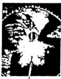
natural_image
Abstract black-and-white pattern with curved and floral-like shapes (no text or symbols)Shadow caused by mast
Figure 6-18 Appearance of a Shadow Sector on the Display Screen
The result of the above measurement should be recorded on a blind shadow sector diagram. Figure 6-20 is an example of a shadow sector diagram for the scanner unit sited as in Figure 6-19. The blind shadow sector diagram should be fixed near the display unit.
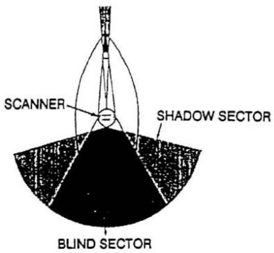
Figure 6-19 Shadows Caused by Objects
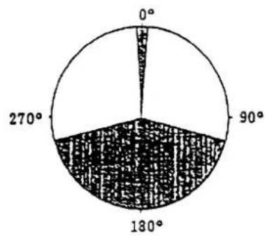
pie
| Angle | Value | |---|---| | 0° | 1 | | 90° | 3 | | 180° | 5 | | 270° | 6 |Figure 6-20 Shadow Sector Diagram
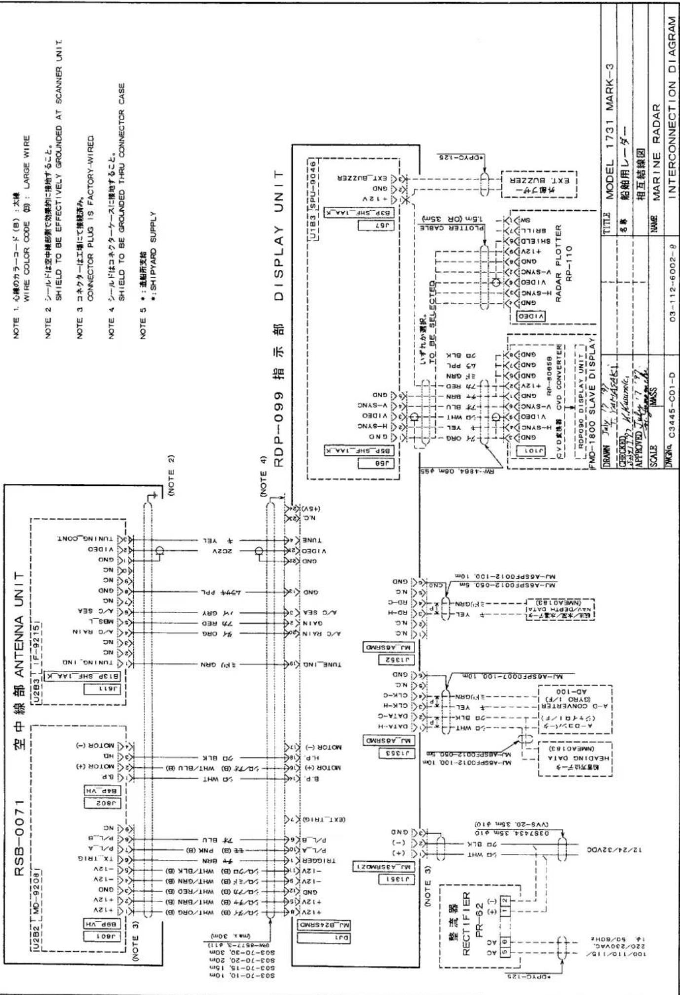
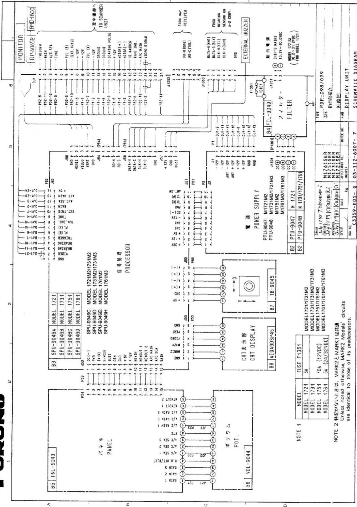
EIBIINA ELECTRIC CO LTD
| NOTE 1 | MODEL | FUSE F1351 |
| MODEL 1721 | 5A | |
| MODEL 1731 | ||
| MODEL 1751 | 10A (12VDC) | |
| MODEL 1761 | 5A (24/32VDC) |
NOTE 2 特記がないときは、MARK2とMARK1は共通
Unless noted otherwise, MARK2 Models' circuits are identical to those of its predecessors.
| DRAWNJuly 1798 T.YAMASAK iCHECKEDJuly 1798 KrasunkiAPPROVEDJuly 1798K.Cusulolo CT | M1761 SERM1751 SERM1731 SERM1721 SER | TYPERDP.-098/099乙体指示部秘合回路图 | ||
| SCALE/ | MASSkg | APPLICABLE TO:(MODEL) | BLOCK NO. | NAMEDISPLAY UNIT |
| DWG NO.C3359-K01-G | 03-112-6007-7 | SCHEMATIC DIAGRAM | ||
FURUNO
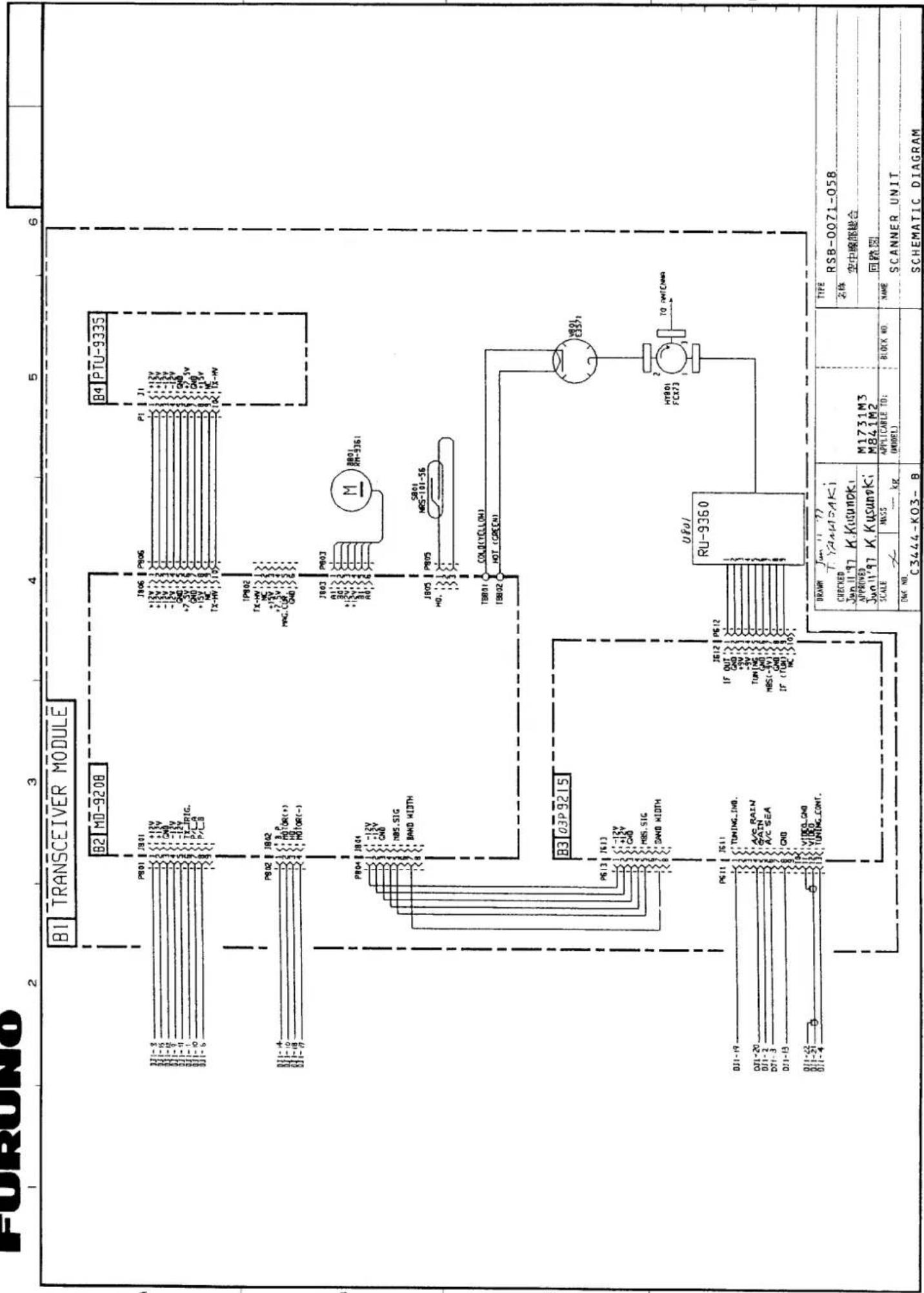
flowchart
graph TD
    subgraph Module_B1
        A["BI"] --> B["B2 MD-9208"]
        B --> C["B3 03P 9215"]
        C --> D["B4 PTU-9335"]
    end

    subgraph Module_B2
        E["BI"] --> F["BI01 JB01"]
        F --> G["BI02 JB02"]
        G --> H["BI03 JB03"]
        H --> I["BI04 JB04"]
        I --> J["BI05 JB05"]
        J --> K["BI06 JB06"]
        K --> L["BI07 JB07"]
        L --> M["BI08 JB08"]
        M --> N["BI09 JB09"]
        N --> O["BI10 JB10"]
        O --> P["BI11 JB11"]
        P --> Q["BI12 JB12"]
    end

    subgraph Module_B3
        R["BI"] --> S["BI13 JB13"]
        S --> T["BI14 JB14"]
        T --> U["BI15 JB15"]
        U --> V["BI16 JB16"]
        V --> W["BI17 JB17"]
        W --> X["BI18 JB18"]
        X --> Y["BI19 JB19"]
        Y --> Z["BI20 JB20"]
        Z --> AA["BI21 JB21"]
        AA --> AB["BI22 JB22"]
        AB --> AC["BI23 JB23"]
        AC --> AD["BI24 JB24"]
    end

    subgraph Module_B4
        AE["BI"] --> AF["BI06 JP06"]
        AF --> AG["BI07 JP07"]
        AG --> AH["BI08 JP08"]
        AH --> AI["BI09 JP09"]
        AI --> AJ["BI10 JP10"]
        AJ --> AK["BI11 JP11"]
        AK --> AL["BI12 JP12"]
        AL --> AM["BI13 JP13"]
        AM --> AN["BI14 JP14"]
        AN --> AO["BI15 JP15"]
        AO --> AP["BI16 JP16"]
        AP --> AQ["BI17 JP17"]
        AQ --> AR["BI18 JP18"]
        AR --> AS["BI19 JP19"]
        AS --> AT["BI20 JP20"]
        AT --> AU["BI21 JP21"]
        AU --> AV["BI22 JP22"]
        AV --> AW["BI23 JP23"]
        AW --> AX["BI24 JP24"]
        AX --> AY["BI25 JP25"]

    subgraph Module_B5
        AZ["BI"] --> BA["BI01 JB01"]
        BA --> BB["BI02 JB02"]
        BB --> BC["BI03 JB03"]
        BC --> BD["BI04 JB04"]
        BD --> BE["BI05 JB05"]
        BE --> BF["BI06 JB06"]
        BF --> BG["BI07 JB07"]
        BG --> BH["BI08 JB08"]
        BH --> BI["BI09 JB09"]
        BI --> BJ["BI10 JB10"]
        BJ --> BK["BI11 JB11"]
        BK --> BL["BI12 JB12"]
        BL --> BM["BI13 JB13"]
        BM --> BN["BI14 JB14"]
        BN --> BO["BI15 JB15"]
        BO --> BP["BI16 JB16"]
        BP --> BQ["BI17 JB17"]
        BQ --> BR["BI18 JB18"]
        BR --> BS["BI19 JB19"]
        BS --> BT["BI20 JB20"]
        BT --> BU["BI21 JB21"]
        BU --> BV["BI22 JB22"]
        BV --> BW["BI23 JB23"]

    subgraph Module_B6
        BX["BI"] --> BY["BI03 JP03"]
        BY --> BZ["MBR-33G-33G-33G-33G-33G-33G-33G-33G-33G-33G-33G-33G-33G-33G-33G-33G-33G-33G-33G-33G-33G-33G-33G-33G-33G-33C<br>    end<br><br>    subgraph Module_B7<br>        CA[BI"] --> CB["MBS-SB-GND-GND-GND-GND-GND-GND-GND-GND-GND-GND-GND-GND-GND-GND-GND-GND-GND-GND-GND-GND-GND-GND-GND-GND-GND-GND-GND-GND-GND-GND-GND-GND-GND-GND-GND-GND-GND-GND-GND-GND-GND-GND-GND-GND-GND-GND-GND-GND-GND-GND-GN<br>    end<br><br>    subgraph Module_B8<br>        DA[C3444-KO3-B<br>    "]
    end

    subgraph Module_B9
        DB[DRAW: Jun 11 77 T YaWTA-Ki
CHECKED: Jun 11 97 K Kusunoki
APPROVED: Jun 11 97 K Kusunoki
SCALE: MSS5 - kg
DWG NO.: (UNDELE)
APPLICABLE TO:
APPROVED TO:
BLOCK NO.
TYPE: RSB-0071-05B
名称: 空中電部総合
回路图
SCANNER UNIT
SCHEMAIC DIAGRAM
FURUNO ELECTRIC CO LTD
注記
TABLE 1 INDICATES TOLERANCE OF DIMENSIONS
2) コンパス安全距離
COMPASS SAFE DISTANCE
Declaration of Conformity
We
FURUNO ELECTRIC CO., LTD.
(Manufacturer)
9-52 Ashihara-Cho, Nishinomiya City, 662-8580, Hyogo, Japan
(Address)
declare under our sole responsibility that the product
Radar Model 1731 MARK-3 for recreational crafts and small fishing boats (Serial No. 3360-0001)
(Model name, serial number)
is in conformity with the essential requirements as described in the Directive 1999/5/EC of the European Parliament and of the Council on radio equipment and telecommunications terminal equipment (R&TTE Directive) and satisfies all the technical regulations applicable to the product within this Directive
EN 60945: 1997-01 (IEC 60945 Third edition: 1996-11)
KSR 142, Annex 1
(title and/or number and date of issue of the standard(s) or other normative document(s))
For assessment, see
- Statement of Opinion N° 00214139/AA/00 of 4 January 2001 issued by KTL Certification, The Netherlands
- Test report 96329200 of 8 April 1997 and 96329201 of 8 April 1997 prepared by Telefication, The Netherlands
On behalf of Furuno Electric Co., Ltd.
Nishinomiya City, Japan
January 15, 2001
(Place and date of issue)
Hiroaki Komatsu
Manager,
International Rules and Regulations
(name and signature or equivalent marking of authorized person)
- SAFETY INSTRUCTIONS
- DANGER
- WARNING
- CAUTION
- NOTICE
- Please Check Input Voltage
- Table of Contents
- FOREWORD ...... v
- SPECIFICATIONS ix
- PRINCIPLE OF OPERATION.... 1-1
- OPERATIONAL OVERVIEW 2-1
- APPLICATION 3-1
- LIST OF DRAWINGS....S-1
- Declaration of Conformity
- FOREWORD
- General Safety Information
- Operating Precautions
- Features
- SPECIFICATIONS
- SCANNER UNIT
- TRANSCEIVER MODULE (contained in radome)
- DISPLAY UNIT
- ENVIRONMENT CONDITION
- POWER SUPPLY & POWER CONSUMPTION
- EQUIPMENT LIST
- PRINCIPLE OF OPERATION
- OPERATIONAL OVERVIEW
- The Front Panel
- Description of controls
- Turning the Unit On and Off
- Basic Operation
- Range selection
- Tips on selecting range
- Adjusting the GAIN control
- Tips on adjusting GAIN
- Adjusting the A/C SEA control
- Tips on adjusting A/C SEA
- Tuning the radar receiver
- Adjusting display brightness
- Adjusting front panel backlighting
- Erasing the heading mark
- Select the cursor data display
- The MENU Touchpad
- Measuring Range and Bearing
- Range
- Fixed range rings
- Cursor/VRM
- Unit of range measurement
- Bearing
- Cursor
- EBL
- Tips on measuring bearing
- Reducing Interference
- Precipitation clutter
- Radar interference
- Shifting and Zooming the Display
- Shift
- Zoom
- Guard Alarm
- Auto In/Out Alarm
- Plotting
- Plot Brilliance
- Better Distinction of Echoes
- WATCHMAN
- APPLICATION
- Factors Affecting Minimum Range
- Sea return
- Vertical beamwidth
- Factors Affecting Maximum Range
- Radar horizon
- Target properties
- Interpreting the Display
- Land targets
- Ship targets
- Echo size
- False Echoes
- Multiple echoes
- Side-Lobe echoes
- Blind and shadow sectors
- Indirect echoes
- Radar Picture and Corresponding Chart
- Position Fixing with Radar
- By radar range
- By range and bearing to a point of land
- By two bearings
- Collision Avoidance and Relative Motion
- Assessing the risk
- MAINTENANCE
- General
- DANGER ELECTRICAL SHOCK HAZARD
- Radome
- Mounting base
- Cleaning the display screen
- Fuse replacement
- TROUBLESHOOTING
- WARNING: RADIO FREQUENCY (RF) RADIATION HAZARD
- Basic Troubleshooting
- Advanced Troubleshooting
- Typical problems and their causes
- 7) Poor sensitivity.
- Checking the Magnetron
- INSTALLATION
- Antenna Unit Installation
- Siting, handling considerations
- Mounting the antenna
- Wiring and final preparation
- Display Unit Installation
- Installation of rubber vibration isolators
- Antenna connection
- Power connection
- Ground connection
- Gyrocompass (or heading sensor) connection (option)
- External navigational receiver connection (option)
- Fuse exchange for 24/32VDC power supplies
- Checking the Installation
- Tick here.
- Adjustments
- Initial procedures
- Sweep timing
- Relative bearing alignment
- MAG or GYRO indication
- Range unit selection
- Magnetron heater voltage
- Measurement of Blind Shadow Sectors
- 50/60Hz
Brand : FURUNO
Model : 1731 Mark-3
Category : Radar maritime