
1944C - Radar maritime FURUNO - Free user manual and instructions
Find the device manual for free 1944C FURUNO in PDF.


| Product Type | Marine Radar Display |
| Display Size | 15 inches (diagonal) |
| Display Resolution | 1024 x 768 pixels |
| Antenna Type | X-band (9.4 GHz) Radome |
| Output Power | 4 kW |
| Range Scales | Up to 72 nautical miles |
| Power Supply | 12-24 VDC (2.0A at 24V) |
| Power Consumption | 55 W (max) |
| Weight (Display Unit) | Approx. 12 kg (26.5 lbs) |
| Weight (Antenna Unit) | Approx. 8 kg (17.6 lbs) |
| Dimensions (Display Unit) | 424 x 424 x 256 mm (16.7 x 16.7 x 10.1 in) |
| Dimensions (Antenna Unit) | Diameter 460 mm, Height 215 mm (18.1 x 8.5 in) |
| Bearing Accuracy | ±1° |
| Minimum Range | 0.125 nautical miles |
| Key Functions | Radar overlay, AIS target display, waypoint navigation |
| Cleaning | Clean display with soft, dry cloth; avoid abrasive cleaners |
| Safety Features | Automatic interference rejection, guard zone alarm |
| Spare Parts Availability | Authorized dealers; user-replaceable fuse and antenna |
| Waterproof Rating | Display: IPX5; Antenna: IPX6 |
Frequently Asked Questions - 1944C FURUNO
User questions about 1944C FURUNO
0 question about this device. Answer the ones you know or ask your own.
Ask a new question about this device
Download the instructions for your Radar maritime in PDF format for free! Find your manual 1944C - FURUNO and take your electronic device back in hand. On this page are published all the documents necessary for the use of your device. 1944C by FURUNO.
USER MANUAL 1944C FURUNO
The paper used in this manual
is elemental chlorine free.
All rights reserved.
Printed in Japan
Pub. No. OME-35430
(DAMI) M1804C SER & GD1920C
Your Local Agent/Dealer
T EDITION · FEB 2005
B. JUN 6, 2005

* 00015180201 *
FURUNO
Marine Radar
MODEL 1824C/1834C/
1934C/1944C/1954C/1964C
Color Video Plotter
GD-1920C

VX2


FURUNO ELECTRIC CO., LTD.
NISHINOMIYA, JAPAN
ELECTRICAL SHOCK HAZARD Do not open the equipment.
Only qualified personnel should work inside the equipment.

Turn off the radar power switch before servicing the antenna unit. Post a warning sign near the switch indicating it should not be turned on while the antenna unit is being serviced.
Prevent the potential risk of being struck by the rotating antenna and exposure to RF radiation hazard.

Wear a safety belt and hard hat when working on the antenna unit.
Serious injury or death can result if someone falls from the radar antenna mast.
Do not disassemble or modify the equipment.
Fire, electrical shock or serious injury can result.
Turn off the power immediately if water leaks into the equipment or the equipment is emitting smoke or fire.
Continued use of the equipment can cause fire or electrical shock.
Use the proper fuse.
Fuse rating is shown on the power cable. Use of a wrong fuse can result in damage to the equipment.
Keep heater away from equipment.
Heat can alter equipment shape and melt the power cord, which can cause fire or electrical shock.

WARNING
Radio Frequency Radiation Hazard
The radar antenna emits electromagnetic radio frequency (RF) energy which can be harmful, particularly to your eyes. Never look directly into the antenna aperture from a close distance while the radar is in operation or expose yourself to the transmitting antenna at a close distance.
Distances at which RF radiation levels of 100 and 10 W/m ^2 exist are given in the table below.
Note: If the antenna unit is installed at a close distance in front of the wheel house, your administration may require halt of transmission within a certain sector of antenna revolution. This is possible - Ask your FURUNO representative or dealer to provide this feature.
| MODEL | Distance to 100 W/m2 point | Distance to 10 W/m2 point | |
| MODEL 1824C | Nil | Worst case 0.50 m | |
| MODEL 1834C | Nil | Worst case 1.80 m | |
| MODEL 1934C | Worst case 0.20 m | Worst case 3.00 m | |
| MODEL 1944C | Nil | Worst case 2.50 m | |
| MODEL 1954C | XN-12A | Nil | Worst case 2.50 m |
| XN-13A | Worst case 2.30 m | ||
| MODEL 1964C | XN-12A | 0.80 m | Worst case 9.50 m |
| XN-13A | 0.60 m | Worst case 8.00 m | |
Warning Label
A warning label is attached to the equipment. Do not remove the label. If the label is missing or damaged, contact a FURUNO agent or dealer.
| WARNING | |
| To avoid electrical shock, do not remove cover. No user-serviceable parts inside. | |
Name: Warning Label (1)
Type: 86-003-1011-0
Code No.: 100-236-230
TABLE OF CONTENTS
FOREWORD ......vi
A Word to the Owner of the Model
18x4C/19x4C Series Marine Radar, GD-1920C
Color Video Plotter...... vi
Features ...... vi
Notice ......vii
SYSTEM CONFIGURATIONS......viii
1. OPERATIONAL OVERVIEW...... 1-1
1.1 Operating Controls.... 1-1
1.1.1 Display unit controls 1-1
1.1.2 Remote controller.... 1-3
1.2 Inserting a Chart Card.... 1-4
1.3 Turning the Unit On/Off 1-5
1.4 Display Brilliance, Panel Brilliance, Hue .. 1-6
1.4.1 Display brilliance, panel brilliance .
1.4.2 Hue....1-7
1.5 Selecting a Display.... 1-8
1.5.1 Display modes 1-8
1.5.2 Selecting a display 1-9
1.5.3 Switching control in combination and overlay screens 1-10
1.5.4 Selecting image source ..... 1-11
1.6 Trackball, Cursor.... 1-12
1.7 Entering the MOB Mark, Setting MOB as Destination.... 1-13
1.8 Data Boxes 1-14
1.8.1 Showing, hiding data boxes with soft key 1-14
1.8.2 Rearranging data boxes ..... 1-14
1.8.3 Temporarily erasing a data box.... 1-14
1.9 Function Keys 1-15
1.10 Simulation Display 1-16
2. RADAR OPERATION ...... 2-1
2.1 Radar Display 2-1
2.2 Transmitting, Stand-by 2-1
2.3 Tuning....2-2
2.4 Adjusting the Gain....2-2
2.5 Reducing Sea Clutter....2-3
2.5.1 How the A/C SEA works....2-3
2.5.2 Adjusting the A/C SEA....2-4
2.6 Reducing Precipitation Clutter 2-4
2.6.1 Adjusting the A/C RAIN 2-4
2.7 Range Scale 2-5
2.8 Pulselength....2-5
2.9 Presentation Mode 2-6
2.9.1 Selecting a presentation mode 2-6
2.9.2 Description of presentation modes
2.10 Measuring the Range....2-8
2.10.1 Measuring range by range rings ... ....
2.10.2 Measuring range by cursor.....2-8
2.10.3 Measuring range by VRM......2-9
2.10.4 Various VRM operations .....2-9
2.11 Measuring the Bearing....2-10
2.11.1 Measuring bearing by cursor . 2-10
2.11.2 Measuring bearing by EBL .... 2-10
2.11.3 Various EBL operations......2-10
2.12 Erasing the Heading Line, North Marker.. 2-11
1.2.13 Reducing Noise Interference 2-11
2.14 Rejecting Radar Interference.... 2-11
2.15 Zoom 2-12
2.15.1 Zooming radar targets .... 2-12 2.15.2 Zooming ARP, TTM targets.... 2-13
2.16 Shifting the Picture 2-14
2.16.1 Manual shift....2-14
2.16.2 Automatic shift....2-14
2.17 Using the Offset EBL....2-15
2.17.1 Predicting collision course ..... 2-15
2.17.2 Measuring range & bearing between two targets .... 2-16
2.18 Echo Trails....2-17
2.18.1 Trail time 2-17
2.18.2 Starting echo trails....2-18
2.18.3 Trail gradation 2-18
2.18.4 Trail color 2-18
2.18.5 Echo trail mode 2-19
2.19 Echo Stretch 2-19
2.20 Echo Averaging....2-20
2.21 Outputting TLL Data 2-21
2.22 Guard Alarm.... 2-22
2.22.1 Setting a guard alarm zone....2-22
2.22.2 When the alarm is violated....2-23
2.22.3 Cancelling the guard alarm....2-23
2.23 Watchman....2-23
2.23.1 How watchman works......2-23
2.23.2 Turning on/off watchman ..... 2-23
2.23.3 Setting watchman stand-by interval
2.24 Suppressing Second-trace Echoes... 2-24
2.25 Waypoint Marker 2-25
2.26 ARP, TTM Operation 2-26
2.26.1 Activating/deactivating ARP, TTM.
2.26.2 Acquiring and tracking targets (ARP).... 2-27
2.26.3 Displaying target number (ARP, TTM) 2-29
2.26.4 Terminating tracking of ARP targets.... 2-29
2.26.5 Setting vector attributes (ARP)2-30
2.26.6 Displaying past position (ARP)2-31
2.26.7 ARP, TTM target data....2-31
2.26.8 CPA/TCPA alarm (ARP)......2-32
2.26.9 Lost target alarm (ARP)......2-33
2.26.10 Showing, hiding ARP target tracks
2.27 Interpreting the Radar Display....2-34
2.27.1 False echoes....2-34
2.27.2 SART (Search and Rescue Transponder)....2-35
2.27.3 Racon (Radar Beacon)......2-36
3. PLOTTER OPERATION .... 3-1
3.1 Plotter Displays....3-1
3.1.1 Full-screen plotter display......3-1
3.1.2 Nav graphic display....3-3
3.1.3 Highway display 3-6
3.1.4 Nav data display....3-7
3.2 Presentation Mode....3-8
3.3 Shifting the Display 3-9
3.4 Chart Scale 3-9
3.5 Chart Cards 3-9
3.5.1 Chart card overview .....3-9
3.5.2 Indices and chart enlargement3-10
3.5.3 Navionics charts.... 3-11
3.5.4 C-MAP charts.... 3-14
3.6 Working with Track....3-18
3.6.1 Displaying track.... 3-18
3.6.2 Stopping, restarting plotting of own ship track 3-19
3.6.3 Changing track color 3-19
3.6.4 Track plotting method and interval for own ship track 3-20
3.6.5 Changing own ship track/mark distribution setting 3-21
3.6.6 Erasing track....3-22
3.7 Marks, Lines....3-23
2-243.7.1 Entering a mark, line....3-23
3.7.2 Changing mark attributes.....3-24
3.7.3 Selecting line type 3-24
3.7.4 Erasing marks, lines 3-25
3.8 Waypoints 3-26
2-27 3.8.1 Entering waypoints .....3-26
3.8.2 Editing waypoint data ...... 3-29
3.8.3 Erasing waypoints 3-30
3.8.4 Changing waypoint mark size (Navionics GOLD)....3-31
3.8.5 Searching waypoints ..... 3-32
3.9 Routes 3-33
3.9.1 Creating routes....3-33
3.9.2 Connecting routes 3-36
3.9.3 Inserting waypoints....3-37
3.9.4 Removing waypoints from a route.
3.9.5 Erasing routes 3-39
32183Navigation....3-39
3.10.1 Navigating to a "quick point" ..3-39
3.10.2 Navigating to waypoints......3-40
3.10.3 Navigating to ports, port services (NavChart™ only)....3-41
3.10.4 Following a route....3-43
3.10.5 Canceling route navigation ....3-46
3.11 Alarms 3-47
3.11.1 Audio alarm on/off 3-47
3.11.2 Arrival alarm....3-48
3.11.3 Anchor watch alarm....3-49
3.11.4 XTE (Cross-Track Error) alarm ....
3.11.5 Speed alarm....3-50
3.11.6 Proximity alarm 3-51
3.11.7 Trip alarm....3-51
3.11.8 Grounding alarm (C-MAP specification) 3-52
3.11.9 Alarm information 3-53
3.12 Resetting Trip Distance 3-55
4.1.3 Selecting screen split method in combination displays ....4-6
4.2 Automatic Sounder Operation .....4-6
4.2.1 How the automatic sounder works
4.2.2 Types of automatic sounder modes.... 4-6
4.2.3 How to enable automatic sounder operation.... 4-7
4.3 Manual Sounder Operation 4-7
4.3.1 Selecting the manual mode ..... 4-7
4.3.2 Selecting display range ..... 4-7
4.3.3 Adjusting the gain....4-8
4.3.4 Shifting the range 4-8
4.4 Measuring Depth, Time 4-9
4.5 Reducing Interference....4-9
4.6 Reducing Low Level Noise....4-10
4.7 Erasing Weak Echoes.... 4-11
4.8 White Marker 4-12
4.9 Picture Advance Speed 4-12
4.9.1 Advancement independent of ship's speed 4-12
4.9.2 Advancement synchronized with ship's speed 4-13
4.10 Display Colors.... 4-14
4.11 Alarms 4-15
4.11.1 Audio alarm on/off 4-15
4.11.2 Bottom alarm....4-16
4.11.3 Fish alarm....4-16
4.11.4 Fish alarm (B/L)....4-17
4.11.5 Water temperature alarm.....4-17
4.11.6 When an alarm setting is violated...
4.12 Water Temperature Graph.... 4-19
4.13 Changing Pulse Repetition Rate..... 4-19
4.14 Saving Sounder Picture to an SD Card....
4.15 Interpreting the Sounder Display ..... 4-20
4.15.1 Zero line....4-20
4.15.2 Bottom echo....4-20
4.15.3 Fish school echoes .... 4-21
4.15.4 Surface noise/Aeration......4-21
5. AIS OPERATION
5.1 Turning AIS Feature On/Off 5-1
5.2 AIS Symbols 5-3
5.3 Setting Number of AIS Targets to Display
5.4 Activating Targets....5-4
5.5 Displaying Target Data 5-4
5.6 Lost Target....5-5
5.7 Setting CPA and TCPA 5-5
5.8 Proximity Alarm.... 5-6
5.9 Showing, Hiding AIS Target Tracks..... 5-7
5.10 Choosing Vector Time 5-7
5.11 Displaying Past Positions of AIS Targets.. 4-6
6. DATA TRANSFER....6-1
6.1 Memory Card Operations....6-1
6.1.1 Deleting all data (other than chart data) from memory cards......6-1
6.1.2 Saving data to a memory card. 6-2
6.1.3 Playing back data from a memory card....6-3
6.2 Uploading, Downloading Data ..... 6-4
6.2.1 Setting communication software on the PC....6-4
6.2.2 Uploading or downloading data ....
6.3 Loading Waypoint Data from Yeoman. 6-7
6.4 Receiving Data Via Network Equipment ..
6.5 Outputting Data Through the Network. 6-9
7. CUSTOMIZING YOUR UNIT......7-1
7.1 General Setup....7-1
7.2 Radar Setup....7-4
7.2.1 Radar display setup....7-4
7.2.2 Radar range setup....7-7
7.2.3 Function key setup .....7-8
7.3 Plotter Setup....7-10
7.3.1 Navigation options.... 7-10
7.3.2 Function key setup 7-11
7.4 Chart Setup....7-13
4-18 7.4.1 Chart offset ....7-13
7.4.2 Navionics GOLD chart attributes...
7.4.3 C-MAP chart attributes ..... 7-15
4-19 7.5 Data Boxes Setup....7-21
7.6 Hot Page Setup....7-22
7.7 Navigator Setup 7-23
7.7.1 Navigation data source...... 7-23
7.7.2 GPS receiver setup (Set equipped with GP-310B/320B)....7-25
7.7.3 TD display setup 7-28
7.8 Nav Data Display Setup 7-30
7.9 Sounder Setup....7-31
7.9.1 System setup 7-31
7.9.2 Sensor setup....7-34
7.9.3 Sounding range, zoom range, bottom lock range.... 7-35
7.9.4 Function key setup 7-36
7.10 Nav Graphic Display Setup 7-38
8. MAINTENANCE, TROUBLESHOOTING. ......8-1
8.1 Preventive Maintenance....8-1
8.2 Replacement of Batteries 8-2
8.3 Replacement of Fuse 8-2
8.4 Replacing the Magnetron 8-3
8.5 Replacing the Synchro Belt (1824C only) 8-3
8.6 Trackball Maintenance 8-3
8.7 Simple Troubleshooting....8-4
8.7.1 General 8-4
8.7.2 Radar....8-4
8.7.3 Plotter 8-5
8.7.4 Sounder 8-6
8.8 Diagnostics 8-7
8.8.1 Memory I/O test....8-7
8.8.2 Test pattern 8-10
8.8.3 Keyboard, remote controller test...
8-11
8.9 GPS Status Display....8-12
8.10 Clearing Memories....8-13
8.11 Error Messages....8-14
APPENDIX....AP-1
Menu Overview.... AP-1
Geodetic Chart List ...... AP-10
Icons AP-11
SPECIFICATIONS....SP-1
INDEX...... IN-1
A Word to the Owner of the Model 18x4C/19x4C Series Marine Radar, GD-1920C Color Video Plotter
FURUNO Electric Company thanks you for purchasing the Model 18x4C/19x4C Series Marine Radar, GD-1920C Color Video Plotter. We are confident you will discover why the FURUNO name has become synonymous with quality and reliability.
For over 50 years FURUNO Electric Company has enjoyed an enviable reputation for quality and reliability throughout the world. This dedication to excellence is furthered by our extensive global network of agents and dealers.
Your equipment is designed and constructed to meet the rigorous demands of the marine environment. However, no machine can perform its intended function unless properly installed and maintained. Please carefully read and follow the operation and maintenance procedures set forth in this manual.
We would appreciate feedback from you, the end-user, about whether we are achieving our purposes.
Thank you for considering and purchasing FURUNO.
Features
The 18x4C/19x4C Radar Series and the GD-1920C Video Plotter work within our network system called the "NavNet." Each product has an IP address to communicate with NavNet compatible products within the network, using TCP/IP protocol through an Ethernet 10BASE-T network.
The main features are as follows:
- This Navnet series consists of the following models:
| Model | Output | Radar antenna size, type, Range rotation speed | |
| Marine Radar Model 1824C 2.2 kW 24 nm | 46 cm, radome, 24/30 rpm (auto-switching) | ||
| Marine Radar Model 1834C 4 kW 36 nm 60 cm, radome, 24 rpm | |||
| Marine Radar Model 1934C 4 kW 48 nm 3.5 ft, open, 24 rpm | |||
| Marine Radar Model 1944C 6 kW 64 nm 4 ft, open, 24 rpm | |||
| Marine Radar Model 1954C 12 kW | 72 nm | 4/6 ft, open, 24 rpm (4 or 6 ft), 48 rpm (4 ft only) | |
| Marine Radar Model 1964C 25 kW | |||
| Color Video Plotter GD-1920C — — — |
- Bright 10.4" screen visible even under direct sunlight.
- User friendly operation with combination of discrete keys, soft keys, alphanumeric keys and Trackball.
- Accepts the following SD chart cards: NAVIONICS GOLD or C-MAP NT ^+ /NT MAX charts, depending on specification. All names mentioned above are registered trademarks of their respective companies.
- Fast chart redraw.
• Built-in NavNet interface circuit board. - Video input (video recorder, CCD device, etc.) available with installation of optional PIP Board.
- 12-channel GPS Receiver GP-310B with highly accurate position fixing optionally available, GP-320B with WAAS capability.
- User programmable function keys.
- Video sounder picture available with connection of the optional Network Sounder ETR-6/10N or ETR-30N.
- The optional facsimile receiver FAX-30 receives facsimile pictures and navtex messages transmitted from facsimile and navtex stations.
Notice
- No part of this manual may be copied or reproduced without written permission.
- If this manual is lost or worn, contact your dealer about replacement.
- The contents of this manual and equipment specifications are subject to change without notice.
- The example screens (or illustrations) shown in this manual may not match the screens you see on your display. The screen you see depends on your system configuration and equipment settings.
- This manual is intended for use by native speakers of English.
- FURUNO will assume no responsibility for the damage caused by improper use or modification of the equipment or claims of loss of profit by a third party.
SYSTEM CONFIGURATIONS
All NavNet products incorporate a “network circuit board” to integrate each NavNet product on board through an optional LAN cable (Ethernet 10BASE-T). Each NavNet product is assigned an IP address to enable transfer of images between other NavNet products. For example, video plotter pictures can be transferred to a radar and vice versa. Pictures received via the NavNet may be adjusted at the receiving end.
The number of display units which may be installed depends on the number of network sounder connected. For a system incorporating three or more products, a “hub” is required to process data.
For one network sounder: one radar and three plotters, or four plotters For two network sounder: one radar and two plotters, or four plotters
Note: NavNet2 equipment cannot be connected to initial version NavNet equipment.
NavNet system (Model 1824C/1834C/1934C/1944C/1954C/1964C)

flowchart
graph TD
    A["Antenna Unit"] --> B["MODEL 1964C"]
    A --> C["MODEL 1954C"]
    A --> D["MODEL 1934C"]
    A --> E["MODEL 1944C"]
    A --> F["MODEL 1834C"]
    A --> G["MODEL 1824C"]
    G --> H["GPS receiver GP-310B/320B"]
    H --> I["Echo sounder Navigator"]
    H --> J["External buzzer PC"]
    H --> K["VGA monitor Remote display Video equipment"]
    H --> L["Heading sensor"]
    H --> M["Other NavNet unit (GD-1920C, etc.)"]
    B --> N["AIS transponder"]
    C --> O["AIS Interface IF-1500AIS*"]
    C --> P["ARPA ARP-11 (Built-in)"]
    C --> Q["Rectifier RU-3423"]
    C --> R["100/110/115/220/230 VAC 1φ, 50/60 Hz*"]
    C --> S["12 - 24 VDC*"]
    C --> T["Facsimile Receiver FAX-30"]
    T --> U["Network Sounder ETR-6/10N ETR-30N"]
    style A fill:#f9f,stroke:#333
    style G fill:#ccf,stroke:#333
    style H fill:#cfc,stroke:#333
    style I fill:#fcc,stroke:#333
    style J fill:#fcc,stroke:#333
    style K fill:#fcc,stroke:#333
    style L fill:#fcc,stroke:#333
    style M fill:#fcc,stroke:#333
    style N fill:#ffc,stroke:#333
    style O fill:#ffc,stroke:#333
    style P fill:#ffc,stroke:#333
    style Q fill:#ffc,stroke:#333
    style R fill:#ffc,stroke:#333
    style S fill:#ffc,stroke:#333
    style T fill:#ffc,stroke:#333
    style U fill:#ffc,stroke:#333
    style V fill:#ffc,stroke:#333
    style W fill:#ffc,stroke:#333
    style X fill:#ffc,stroke:#333
    style Y fill:#ffc,stroke:#333
    style Z fill:#ffc,stroke:#333
    style AA fill:#ffc,stroke:#333
    style AB fill:#ffc,stroke:#333
    style AC fill:#ffc,stroke:#333
    style AD fill:#ffc,stroke:#333
    style AE fill:#ffc,stroke:#333
    style AF fill:#ffc,stroke:#333
    style AG fill:#ffc,stroke:#333
    style AH fill:#ffc,stroke:#333
    style AI fill:#ffc,stroke:#333
    style AJ fill:#ffc,stroke:#333
    style AK fill:#ffc,stroke:#333
    style AL fill:#ffc,stroke:#333
    style AM fill:#ffc,stroke:#333
    style AN fill:#ffc,stroke:#333
    style AO fill:#ffc,stroke:#333
    style AP fill:#ffc,stroke:#333
    style AQ fill:#ffc,stroke:#333
    style AR fill:#ffc,stroke:#333
    style AS fill:#ffc,stroke:#333
    style AT fill:#ffc,stroke:#333
    style AU fill:#ffc,stroke:#333
    style AV fill:#ffc,stroke:#333
    style AW fill:#ffc,stroke:#333
NavNet system (Model 1824C/1834C/1934C/1944C/1954C/1964C)
Single-unit NavNet system (GD-1920C)

flowchart
graph TD
    A["GPS receiver GP-310B/320B"] --> B["AIS Interface IF-1500AIS*"]
    C["Other NavNet Unit (Model 1834C, etc.)"] --> D["Display unit RDP-149"]
    D --> E["AIS transponder"]
    D --> F["Remote Controller RMC-100"]
    D --> G["External buzzer"]
    D --> H["VGA monitor Remote display PC Video equipment"]
    D --> I["ARPA ARP-11"]
    D --> J["Echo sounder Navigator"]
    D --> K["Rectifier PR-62"]
    D --> L["12 - 24 VDC"]
    D --> M["Network Sounder ETR-6/10N ETR-30N"]
    D --> N["Facsimile Receiver FAX-30"]
    D --> O["100/110/115/220/230 VAC 1φ, 50/60 Hz"]
    style A fill:#f9f,stroke:#333
    style C fill:#f9f,stroke:#333
    style D fill:#ccf,stroke:#333
    style E fill:#cfc,stroke:#333
    style F fill:#cfc,stroke:#333
    style G fill:#cfc,stroke:#333
    style H fill:#cfc,stroke:#333
    style I fill:#cfc,stroke:#333
    style J fill:#cfc,stroke:#333
    style K fill:#cfc,stroke:#333
    style L fill:#cfc,stroke:#333
    style M fill:#cfc,stroke:#333
    style N fill:#cfc,stroke:#333
    style O fill:#cfc,stroke:#333
    style P fill:#cfc,stroke:#333
    style Q fill:#cfc,stroke:#333
    style R fill:#cfc,stroke:#333
    style S fill:#cfc,stroke:#333
    style T fill:#cfc,stroke:#333
    style U fill:#cfc,stroke:#333
    style V fill:#cfc,stroke:#333
    style W fill:#cfc,stroke:#333
    style X fill:#cfc,stroke:#333
    style Y fill:#cfc,stroke:#333
    style Z fill:#cfc,stroke:#333
Single-unit NavNet system (GD-1920C)
Two-unit NavNet system

flowchart
graph TD
    A["Radar Antenna Unit OR GPS Receiver GP-310B/320B"] --> B["Radar or PLOTTER"]
    C["Radar Antenna Unit OR GPS Receiver GP-310B/320B"] --> D["Radar or PLOTTER"]
    B --> E["Radar, plotter data"]
    D --> E
    E --> F["Radar, plotter data"]
Two-unit NavNet system
Three-or-more-unit NavNet system (Max. 4 display units)

flowchart
graph TD
    A["Radar Antenna Unit OR GPS Receiver GP-310B/320B"] --> B["HUB"]
    C["Radar Antenna Unit OR GPS Receiver GP-310B/320B"] --> B
    B --> D["Sounder data"]
    B --> E["Facsimile data"]
    B --> F["Network Sounder ETR-6/10N ETR-30N (option)"]
    B --> G["Facsimile Receiver FAX-30 (option)"]
    B --> H["Network Sounder ETR-6/10N ETR-30N (option)"]
    B --> I["Plotter data"]
    B --> J["Radar or PLOTTER"]
    B --> K["Radar data"]
    style A fill:#f9f,stroke:#333
    style C fill:#f9f,stroke:#333
    style B fill:#ccf,stroke:#333
    style D fill:#cfc,stroke:#333
    style E fill:#cfc,stroke:#333
    style F fill:#cfc,stroke:#333
    style G fill:#cfc,stroke:#333
    style H fill:#cfc,stroke:#333
    style I fill:#cfc,stroke:#333
    style J fill:#cfc,stroke:#333
    style K fill:#cfc,stroke:#333
Three-or-more-unit NavNet system
1. OPERATIONAL OVERVIEW
This chapter provides the basic information needed to get you started using your radar, video plotter.
1.1 Operating Controls
1.1.1 Display unit controls
Display unit controls
The radar, video plotter, sounder and chart systems are operated with the controls of the display unit (and the remote controller). Ten keys are labeled and they provide the function shown on their labels. The five soft keys provide various functions according to current operating mode. The ENTER knob mainly functions to register selections on the menu and adjust the EBL, VRM and gain. The Trackball's main function is to move the cursor across the screen. When you correctly execute an operation, the unit generates a beep. Invalid operation causes the unit to emit three beeps.

*: When it has been some time since the trackball was last operated, the cursor may not track the movement of the trackball. In this case, move the trackball rapidly and then finely.
1. OPERATIONAL OVERVIEW
Soft keys
The function of the five soft keys changes according to the operation. Their labels for their current functions are shown on the screen to the left of the keys. To hide or show the soft keys, press the HIDE/SHOW key. Each press of the key shows preset soft keys, user function keys or turns off navigation information (at the top of the screen).

Display unit
Some soft keys show the current setting of a soft key in reverse video as shown below.

Radar Display

Plotter Display
Radar and plotter displays
1.1.2 Remote controller

Operating distance
90°: Up to 5 m
±45°: Up to 3 m
Replace the batteries (AA) when the distance from which the display unit can be operated shortens.
Note: The remote controller may become damaged if dropped. Mishandling of the remote controller is not covered by the warranty.
Remote controller
| Key | Function | Key | Function |
| RANGE | Same as RANGE key on display unit. | ENT | Same as ENTER knob on display unit. |
| DISP | Same as DISP key on display unit. | CLEAR | Same as CLEAR key on display unit. |
| SAVE MOB | Same as SAVE/MOB key on display unit. | MENU | Same as MENU key on display unit. |
| Ten keys Enter alphanumerics. BRILL Adjusts display brilliance. | |||
| EBL/VRM | Same as EBL/VRM key on display unit. | TONE | Not used. |
| GAIN | Same as GAIN key on display unit. | TX/STBY | Toggles radar between standby and transmit. |
| WPT | Displays “alphabet” WPT list on plotter display. | ACQ | Acquires radar target.(Requires radar source equipped with ARP.) |
| MARK ENT | Same as MARK ENTRY soft key. | ALARM | Same as ALARM key on the display unit. |
| CENTER | Returns own ship to screen center on plotter display. | HIDE/SHOW | Same as HIDE/SHOW key on display unit. |
| CNTL | Switches control between displays on combination displays. | SK1 – SK5 (soft keys) | Same as soft keys on display unit. |
1. OPERATIONAL OVERVIEW
1.2 Inserting a Chart Card
Your unit reads SD cards, in the following formats: Navionics GOLD Chart cards or C-MAP NT ^+ /NT MAX chart cards, depending on the type of display unit you have. Insert the appropriate chart card for your area as follows:
- Open the chart drive.

Display unit
- Insert chart card label side up prior to turning on the power.
- Close the lid.
To remove chart card, follow the steps shown below.
- Press the MENU key to show the menu.
- Press the SHOW/HIDE soft key.
- Open the chart drive lid, and then push the card once and then pull it out.
Note 1: Do not remove a card while the chart is being drawn. This may cause the equipment to freeze.
Note 2: Do not insert or remove a card while the power is on. This may cause the equipment to freeze.
Note 3: For multiple display units, do not use the same chart card type in more than one display unit.
Note 4: Remove the card with care; rough handling can damage the card and destroy its contents.
1.3 Turning the Unit On/Off
Press the POWER/BRILL key to turn the unit on. A beep sounds and then the equipment shows the startup NavNet screen (about 20 seconds), the product information screen, startup test results and chart usage disclaimer. During this period the equipment is inoperative. The startup test checks the ROM, RAM, internal battery and backup data for proper operation, displaying the results for each as OK or NG (No Good). If NG appears an appropriate message appears on the screen. For any NG, try to press any key to go to the chart disclaimer screen, then perform the diagnostic test as shown in the paragraph “8.8 Diagnostics.”
For start up with the radar display, the magnetron takes from one minute and thirty seconds to three minutes (depending on radar model) to warm up before the radar can be operated. The time remaining for warming up of the magnetron is counted down at the center of the display.
You may press any key at the chart disclaimer screen to show the last-used display, or wait several seconds to let the equipment do it for you.
To turn the unit off, press and hold down the POWER/BRILL key until the screen goes off (approx. 3 sec.). To protect the LCD attach the hard cover. Note that the network sounder will be turned off approx. three minutes after turning off the power. This is due to the system's electrical characteristics.
Note: The first time you turn on the power (or any time the power is applied after a memory reset), you are asked if you want to start the simulation mode, which provides simulated operation of the equipment after the installation mode selection. Push the ENTER knob to start the simulation mode, or press the CLEAR key to start normal operation. For further details about the simulation mode, see the paragraph "1.10 Simulation Display."
1. OPERATIONAL OVERVIEW
1.4 Display Brilliance, Panel Brilliance, Hue
You can adjust display brilliance, panel brilliance and hue as shown below.
1.4.1 Display brilliance, panel brilliance
- Press the POWER/BRILL key momentarily. A set of soft keys for adjustment of brilliance and hue appear.

Brilliance adjustment soft keys
- Press the DISPLY BRILL or PANEL BRILL soft key as appropriate. An adjustment window appears at the bottom of the screen. This window shows the name of the item selected for adjustment plus current brilliance level, by bar graph.

Display brilliance

Panel brilliance
Display brilliance and panel brilliance windows
- Adjust the ENTER knob, clockwise to raise the setting or counterclockwise to decrease it. You may also use the soft key pressed at step 2. Eight levels of display brilliance and panel brilliance are available.
- Hit the RETURN soft key to finish.
Note 1: If the unit is turned off with minimum brilliance, the screen will be dark at the next power-up. Press the POWER/BRILL key consecutively to adjust the brilliance.
Note 2: This equipment does not have a contrast control.
1.4.2 Hue
You may select the colors for the radar and plotter displays as below.
- Press the POWER/BRILL key momentarily.
- Press the HUE soft key to show the hue setting window.

- Operate the Trackball to select hue desired, referring to the table below. MANUAL SET follows the color settings on the CHART DETAILS menu for the plotter and the RADAR DISPLAY SETUP menu for the radar.
| Night | Day | ||
| Characters | Red | Black | Green |
| Radar ring Red Green | Green Green | ||
| Radar echo Orange | Multi Yellow | ||
| Background | Black | White | Blue |
| Landmass (plotter) | Orange* | Light-orange* | Orange* |
Twilight
* = Beige and light-beige on C-MAP display unit.
- Hit the RETURN soft key to finish.
Note: When using the overlay screen, the own ship track will be hidden if the radar background and own ship track are blue and the "MANUAL SET" hue setting is used. In this case, set HUE to other position and then return to "MANUAL" to show the own ship track in black.
1. OPERATIONAL OVERVIEW
1.5 Selecting a Display
1.5.1 Display modes
If you have a radar, navigator, network sounder and external video source (video recorder, etc., optional PIP board required) six full-screen displays are available: radar, plotter, echo sounder, nav data, overlay, and external video. In addition to the full-screen display, you can divide the screen into halves and thirds to show two and three sets of images on a combination display.

Full screen (radar)

Combination screen (radar + plotter)

Overlay screen (plotter + radar only, requires L/L data)
Display screens
The table below shows the displays available with each screen type.
Screen type and available display screen
| Full screen Combination | screen options(half- or thirds-screen) | Overlay screen options |
| Plotter, radar, sounder, nav data, external video, overlay | Plotter, radar, sounder, compass (or wind), highway, compass (or wind)/highway, nav data, overlay, external video | Radar + plotter |
1.5.2 Selecting a display
- Press the DISP key to show the display screen selection window. The icons of modes not available are shaded. HOTPAGE 1-HOTPAGE 6 are user-arrangeable displays called "hot pages," which you can configure as you like. For further details, see the paragraph "7.6 Hot Page Setup."

flowchart
graph TD
    A["Selected item"] --> B["RADAR"]
    B --> C["PLOTTER"]
    C --> D["SOUNDER"]
    D --> E["NAV DATA"]
    E --> F["OVERLAY"]
    F --> G["EXT VIDEO"]
    G --> H["WX FAX"]
    I["HOTPAGE 1"] --> J["HOTPAGE 2"] --> K["HOTPAGE 3"] --> L["HOTPAGE 4"] --> M["HOTPAGE 5"] --> N["HOTPAGE 6"]
    O["TURN KNOB TO SELECT MODE AND PUSH KNOB TO ENTER."] --> P["PUSH ANY SOFT KEY TO SELECT IMAGE SOURCE."]
Display screen selection window
Note: "WX FAX" is available only when the facsimile receiver FAX-30 is connected. If the message "AUX SOURCE IS DISCONNECTED. PUSH ENT KNOB TO EXIT." appears, press the ENTER knob and select other item.
- Rotate the ENTER knob to select a basic display screen or a hot page screen.
- Push the ENTER knob.
- If you select a basic display screen, a group of appropriate combination displays appear. In the example below, the radar combination screens are shown. When WX FAX is selected at step 2, a combination display does not appear.

flowchart
graph TD
    A["Target"] --> B["Grid"]
    B --> C["Grid"]
    C --> D["Grid"]
    D --> E["Grid"]
    E --> F["Grid"]
    F --> G["Grid"]
    G --> H["Grid"]
    H --> I["Grid"]
    I --> J["PUSH ENTER KNOB."]
    J --> K["Return"]
Radar combination screen selection window
- Rotate the ENTER knob to select display desired.
- Push the ENTER knob to finish.
1. OPERATIONAL OVERVIEW
1.5.3 Switching control in combination and overlay screens
A soft key is provided in relevant combination and overlay screens to switch control between displays. In the example below, the CNTRL PLOTTR and CNTRL SNDR soft keys enable switching control between the plotter and sounder screens in the plotter/sounder combination display.

How to switch control between modes in the plotter/sounder combination display
1.5.4 Selecting image source
When more than one network radar or network sounder is connected to the equipment, you may select an image source for each as shown below. This is not necessary when only one network radar or network sounder is connected.
- Press the DISP key.
- Press any soft key to show the following display.

Select source menu
- Use the Trackball to select RADAR SOURCE, SOUNDER SOURCE or AUX SOURCE as appropriate, then press the EDIT key.

Radar source

Aux source
Radar source and sounder source windows
- Use the Trackball to choose source.
- Push the ENTER knob to set.
- Press the DISP key to finish.
- Turn the power off and on again.
1. OPERATIONAL OVERVIEW
1.6 Trackball, Cursor
The Trackball functions to shift the cursor, for measurement of range and bearing to a location (radar) and latitude and longitude position (plotter). Roll the Trackball to shift the cursor. The cursor moves in the direction of Trackball rotation.

Radar Display

Plotter Display
Cursor, cursor data
1.7 Entering the MOB Mark, Setting MOB as Destination
The MOB mark functions to mark man overboard position. You can inscribe the mark from any mode except nav data, when playing back data or conducting any test. Note that this function requires position data.
Note: The function of the SAVE/MOB key depends on the setting of SAVE MOB KEY FUNCTION in the GENERAL SETUP menu. The description below shows the procedure using the default setting. For further details, see Save MOB Key Function on page 7-2.

flowchart
graph TD
    A["Man overboard"] --> B["Range, bearing"]
    B --> C["Current position"]
    D["MOB Data Box"] --> E["M (MOB)"]
    E --> F["MOB mark"]
    F --> G["162.5° M, 0.49 nm"]
MOB concept
- Press and hold down the SAVE/MOB key for about three seconds when someone falls overboard. The display shows the waypoint number being saved (youngest empty waypoint number, 001-999) followed by the MOB confirmation window.
Time remaining is counted down while pressing the SAVE/MOB key.

flowchart
graph TD
    A["WAYPOINT SAVED!"] --> B["XXXWPT CONTINUE PUSHING FOR MOB!"]
    B --> C["CONTINUE PUSHING FOR MOB!"]
    C --> D["XX SEC"]
    D --> E["MAN OVER BOARD! GO TO MOB? YES ... PUSH ENTER KNOB NO ... PUSH CLEAR KEY"]
    F["XXX = Waypoint number"] --> B
    G["XX = Time remaining is counted down."] --> C
MOB mark messages
-
Push the ENTER knob to select the MOB position as the destination, or press the CLEAR key to only mark current ship's position as a waypoint. If you select the MOB position as destination;
-
A full-screen radar, plotter or overlay appears depending on the display in use, with the range set to 0.5 nm. Further, the waypoint marker appears on the radar display.
- The MOB mark "MOB" appears at the MOB position and a blue line runs between it and current position. This line shows the shortest course to the MOB position.
- Range and bearing to the MOB position are shown in the MOB data box.
To erase an MOB mark from the plotter display, you must first erase its corresponding waypoint. Place the cursor on the MOB mark, then press the CLEAR key followed by pushing the ENTER knob to erase the waypoint. Then, repeat to erase the MOB mark.
Note: On the plotter display, this function can be done by pressing the uppermost soft key. For detail, see page 7-10.
1. OPERATIONAL OVERVIEW
1.8 Data Boxes
Data boxes, providing navigation data, may be shown on any full-screen display. Up to six data boxes (two in case of large characters) may be shown, and the default data boxes are position (in latitude and longitude), course over ground, speed over ground and trip log. The user may choose which data to display, where to locate it, and show or hide it as desired. In addition, data boxes may be set independently for each display mode (plotter, radar, sounder). For how to select data for the data boxes, see the paragraph "7.5 Data Boxes Setup."

1.8.1 Showing, hiding data boxes with soft key
Plotter: D. BOX ON/OFF
Radar: ZOOM & D. BOX → D. BOX ON/OFF (EBL/VRM data box, cursor data box also shown/hidden)
Sounder: AUTO/D. BOX→D. BOX ON/OFF
1.8.2 Rearranging data boxes
You may select the location for data boxes as follows:
- Using the Trackball, place the cursor inside the data box you wish to move. As the cursor enters the box it changes to a "hand". Push the ENTER knob, and the hand changes to a fist, meaning the box is correctly selected.
- Use the Trackball to move the data box to the location desired, then push the ENTER knob.
1.8.3 Temporarily erasing a data box
If a data box is obscuring a desired object, you may temporarily erase the box. Use the Trackball to place the cursor inside the data box you wish to erase, then press the CLEAR key. To redisplay the box, press the D. BOX soft key twice to display it.
1.9 Function Keys
The function keys provide for one-touch execution of a desired function. The default function key settings are as shown in the table below.
| Function Key | Default Setting, Key Label | ||
| Radar | Plotter | Sounder | |
| #1 Heading line on/off, HL Track on/off, TRK TLL output, TLL | |||
| #2 Rings on/off, RNG Edit mark/line, EML Clutter, CLT | |||
| #3 Echo trail, TRL Ruler, RUL Signal level, SLV | |||
| #4 | Offcenter, OFC | Add new waypoint, ADD | Noise limiter, NL |
| #5 | STBY/TX, TX | Waypoint alphanumeric list, ALP | Picture advance, PA |
Executing a function
- Press the HIDE/SHOW key to replace the preset soft key labels with the function key labels.


Function keys
- Press function key desired.
Note: Function keys can be individually programmed for the plotter, radar and sounder displays. For further details see the following:
Radar: paragraph 7.2.3
Plotter: paragraph 7.3.2
Sounder: paragraph 7.9.4
1. OPERATIONAL OVERVIEW
1.10 Simulation Display
The simulation display, for use by service technicians for demonstration purposes, provides simulated operation to help acquaint you with the many features your unit has to offer. It allows you to view and control a simulated plotter, radar and sounder picture, without position-fixing equipment, network radar or a network sounder. Most controls are operative, thus you may practice setting destination, enter waypoints, measure range and bearing to a target, etc. Three simulation displays are provided for both the radar and echo sounder.
The simulation icon (SIM) appears when any simulation mode is active.
To start the simulation display;
- Press the MENU key.
- Press the SYSTEM CONFIGURATION, SYSTEM SETUP and SIMULATION SETUP soft keys in that order.

Simulation setup menu
- Follow appropriate procedure on the next several pages. To stop the simulation mode and return to normal operation, choose LIVE for radar, sounder or plotter.
Radar
NavNet display unit-generated echoes or user data
- Select RADAR, then press the EDIT soft key.

- Select BUILT IN DATA 1 or 2 for internally generated echoes or USER DATA for user-saved radar data. Push the ENTER knob.
- Press the MENU key to close the menu.
NavNet radar antenna-generated echoes (not available with the GD-1920C)
- Select GET RADAR SIMULATION DATA, then press the EDIT soft key.
- Select YES, then push the ENTER knob to erase simulation data and get new data. The message "Now getting demo data. Do not turn off display unit." appears while the unit is receiving radar data.
Note: If the network radar could not be found “Radar source is not found. Cannot get demo data.” appears. And if the radar is not active, the message “Radar is not active. Cannot get demo data.” is displayed. Check that the radar is plugged in and its signal cable is firmly fastened. - Select RADAR, then press the EDIT soft key.
- Select SIMULATION 2, then push the ENTER knob.
- Press the MENU key to close the menu.
Plotter
- Select PLOTTER, then press the EDIT soft key.
- Select SIMULATION, then push the ENTER knob.
- Select SPEED, then press the EDIT soft key.
- Enter speed (setting range, 0-99 kt, default speed, 0 kt) with the alphanumeric keys, then push the ENTER knob.
- Select COURSE, then press the EDIT soft key.
- Select "8 FIGURE" to trace the simulated ship's track in a figure-eight course, or enter your own course at DIRECTION. To enter course, use the Trackball to select digit, and enter value with the alphanumeric keys.
- Press the ENTER soft key.
- Select LATITUDE, then press the EDIT soft key.
- Enter latitude (setting range, 85°N-85°S, default setting, 45°35.000'N), then push the ENTER knob.
- Select LONGITUDE, then press the EDIT soft key.
- Enter longitude (setting range, 180°E-180°W, default setting, 125°00.000'W), then push the ENTER knob.
- Select START DATE & TIME, then press the EDIT soft key.
- Enter start date and time, then push the ENTER knob.
- Press the MENU key to close the menu.
Sounder
- Select SOUNDER, then press the EDIT soft key.
-
Select BUILT IN DATA (internally generated echoes) or ETR (network sounder-generated echoes), then push the ENTER knob.
Note: The depth, shift, bottom-zoom, bottom-lock and bottom discrimination cannot be shown in the BUILT IN DATA mode. -
Press the MENU key to close the menu.
This page intentionally left blank.
2. RADAR OPERATION
This chapter covers radar operation, including the ARP (Auto Plotter) function. ARP requires a Model 18x4C/19x4C series network radar equipped with the ARP circuit board.
2.1 Radar Display

Radar display
2.2 Transmitting, Stand-by
- Confirm that the network radar is plugged in.
- Press the DISP key to select a radar display.
- Press the POWER/BRILL key momentarily.
- Press the RADAR STBY soft key to highlight TX on its label.
- Press the RETURN soft key.
When the radar picture is not required, but you want keep it in a state of readiness, press the RADAR TX soft key to highlight STBY on its label.
2. RADAR OPERATION
2.3 Tuning
The radar receiver can be tuned automatically or manually, and the default tuning method is automatic. If you require manual tuning, do the following:
- Press the MENU key to display the main menu.
- Press the RADAR DISPLAY SETUP soft key.
- Select TUNING, then press the EDIT soft key.

Tuning window
- Choose MAN.
- Adjust the ENTER knob until the tuning bar is at its longest position.
- Press the MENU key to close the menu.
Note: If the auto setting does not provide satisfactory tuning, ask your dealer how to re-adjust tuning.
2.4 Adjusting the Gain
The GAIN key adjusts the gain sensitivity of the radar receiver. It works in a manner similar to that of volume control of a broadcast receiver, which amplifies received signals.
The proper setting is such that the background noise is just visible on the screen. If your gain setting is too low, weak echoes may be missed. On the other hand, excessive gain yields too much background noise; strong targets may be missed because of the poor contrast between desired echoes and the background noise on the display.
To adjust the receiver sensitivity, transmit on long range, and then do the following:
-
Press the GAIN key to show the "gain adjustment" soft keys, and the last-used adjustment window appears. The example below shows the gain sensitivity adjustment window. The gain soft keys shown depend on radar source as shown below.
-
If the gain sensitivity window is not displayed, press the GAIN soft key to show the gain sensitivity setting window.
-
Use the Trackball to select AUTO ROUGH, AUTO MODERATE, AUTO CALM, or MAN (manual) as appropriate. Select an AUTO option according to the
-
For manual adjustment, rotate the ENTER knob to adjust, while observing the radar echo. The range of adjustment is 0-100.
- Press the GAIN key on the front panel or the RETURN soft key to finish.

Gain sensitivity window
Adjusting the FTC (When the radar source is the 17x4 series radar)
To suppress rain clutter from heavy storms or scattered rain clutter, adjust the FTC. In addition to reducing clutter, the FTC can be used in fine weather to clarify the picture when navigating in confined waters. However, with the circuit active the receiver is less sensitive. Therefore, turn off the FTC, by setting it for "0", when its function is not required.
- Press the GAIN key.
- Press the FTC soft key to show the FTC window.
- Rotate the ENTER knob to adjust. The range of adjustment is 0-100(%). Do not overadjust the FTC – weak target echoes may be missed.
- Press the GAIN key on the front panel or RETURN soft key to finish.
2.5 Reducing Sea Clutter
2.5.1 How the A/C SEA works
Echoes from waves can be troublesome, covering the central part of the display with random signals known as “sea clutter”. The higher the waves and the higher the antenna above the water, the further the clutter will extend. Sea clutter may affect radar performance because real targets are sometimes hidden by the echoes of small waves. (See the left-hand figure in the figure below.) When sea clutter masks the picture, adjust the A/C SEA to reduce the clutter.
The A/C SEA reduces the amplification of echoes at short ranges (where clutter is the greatest) and progressively increases amplification as the range increases, so amplification will be normal at those ranges where there is no sea clutter.

natural_image
Circular diagram with a central cluster of black dots and a vertical line, no text or symbols present.Sea clutter at screen center

natural_image
Circular diagram with scattered black dots and a vertical line, no text or symbols presentA/C SEA adjusted; sea clutter suppressed
Effect of A/C SEA
2. RADAR OPERATION
2.5.2 Adjusting the A/C SEA
A/C SEA should be adjusted so that the clutter is broken up into small dots, and small targets become distinguishable.
- Press the GAIN key.
- Press the A/C SEA soft key to show the A/C SEA setting window.

A/C SEA setting window
- Use the Trackball to select AUTO ROUGH, AUTO MODERATE, AUTO CALM, or MAN (manual) as appropriate. Select an AUTO option according to the sea state.
- For manual adjustment, rotate the ENTER knob to adjust. The range of adjustment is 0-100. Do not overadjust – weak echoes may be missed.
- When the radar source is the Model 18x4 or 19x4, A/C SEA and A/C RAIN can be automatically adjusted, with the A/C AUTO ON/OFF soft key. Press the key to highlight ON or OFF as appropriate. Note that A/C AUTO adjustment is done at MAN indicator in the A/C SEA window.
- Press the GAIN key on the front panel or RETURN soft key to finish.
2.6 Reducing Precipitation Clutter
The vertical beamwidth of the antenna is designed to see surface targets even when the ship is rolling. However, by this design the unit will also detect precipitation clutter (rain, snow, hail, etc.) in the same manner as normal targets. Precipitation clutter shows as random dots on the screen.
2.6.1 Adjusting the A/C RAIN
When echoes from precipitation mask solid targets, adjust the A/C RAIN to split up these unwanted echoes into a speckled pattern, making recognition of solid targets easier.
- Press the GAIN key.
- Press the A/C RAIN soft key to show the A/C RAIN window.

A/C RAIN setting window
- Rotate the ENTER knob to adjust the A/C RAIN. The current level is shown on the A/C RAIN level bar in the A/C RAIN window, and the range of adjustment is 0 to 100(%). Do not overadjust – weak echoes may be missed.
- Press the GAIN key on the front panel or RETURN soft key to finish.
2.7 Range Scale
The range setting determines the size of the area (in nautical miles) that will appear on your display. In addition, the range setting will also automatically adjust the range ring interval so that accurate range measurements may be made while operating on any range setting.
The range, range ring interval and pulselength appear at the top left-hand corner of the display.
Press the [RANGE (+ or -)] key to change the range scale.
Range scales (nm, sm)
| Range | 0.125 | 0.25 | 0.5 | 0.75 | 1 | 1.5 | 2 | 3 | 4 | 6 | 8 | 12 | 16 | 24 | 36 | ||||
| Ring Interval | 0.0625 | 0.125 | 0.125 | 0.25 | 0.25 | 0.5 | 0.5 | 1 | 1 | 2 | 2 | 3 | 4 | 6 | 12 | 12 | 16 | 18 | |
| No. of Rings | 2 | 2 | 5 | 4 | 5 | 4 | 5 | 4 | 5 | 4 | 5 | 5 | 5 | 5 | 4 | 5 | 5 | 5 | 5 |
Range scales (km)
| Range | 0.25 | 0.5 | 0.75 | 1 | 1.5 | 2 | 3 | 4 | 6 | 8 | 12 | 16 | 24 | 36 | 48 | 64 | 72 |
| Ring Interval | 0.125 | 0.25 | 0.25 | 0.25 | 0.5 | 0.5 | 1 | 1 | 2 | 2 | 3 | 4 | 6 | 12 | 12 | 16 | 18 |
| No. of Rings | 2 | 2 | 4 | 5 | 4 | 5 | 4 | 5 | 4 | 5 | 5 | 5 | 5 | 4 | 5 | 5 | 5 |
Note 1: Maximum range depends on the network radar as shown below.
Model 1824C: 24 nm
Model 1834C: 36 nm
Model 1934C: 48 nm
Model 1944C: 64 nm
Model 1954C, 1964C: 72 nm
Note 2: You may choose which ranges to use from the RADAR RANGE SETUP menu. For details see paragraph 7.2.2. This function is not available with the GD-1920C.
2.8 Pulselength
The pulselength in use is displayed at the upper left corner of the display. Appropriate pulselengths are preset to individual range scales. Therefore, you are not usually required to select them. If you are not satisfied with the current pulselength setting, however, it is possible to change it for the ranges shown below. Generally, select a longer pulse for longer detection range and shorter pulse for better range discrimination.
1.5 nm, 1.5 sm, 3 km: Short pulse, medium pulse
3 nm, 3 sm, 6 km: Medium pulse, long pulse
- If not displayed, press the HIDE/SHOW key to show the radar soft keys.
- Press the SIGNAL PROC. soft key.
2. RADAR OPERATION

Signal process soft keys
3. Choose the 1.5 nm or 3 nm with the RANGE key.
4. Press the PULSE soft key to select the pulselength setting. SHORT or MEDIUM for 1.5 nm, 1.5 sm, 3 km and MEDIUM or LONG for 3 nm, 3 sm, 6 km.
5. Press the RETURN soft key to finish.
2.9 Presentation Mode
This unit provides four radar presentation modes: head-up, course-up, north-up and true motion.
Heading data is required for modes other than head-up.
2.9.1 Selecting a presentation mode
-
If not displayed, press the HIDE/SHOW key to show the radar soft keys.
-
Press the RADAR DISPLAY soft key to show the RADAR DISPLAY soft keys.
-
Press the MODE soft key. Each pressing of the key changes the presentation mode and the presentation mode indication in the sequence of North-up, True Motion, Head-up, and Course-up.
| Function | Indicator on display | Soft key label |
| North-up | N-UP | NTH UP |
| True Motion | TR-M | TRUE M |
| Head-up | H-UP | HD UP |
| Course-up | C-UP | CSE UP |
- Press the RETURN soft key to finish.
Note: When heading data is lost, the presentation mode automatically goes to head-up, the heading indication at the screen top shows “- - -.-°” and the audio alarm sounds. Press the ALARM key to acknowledge the alarm. The message “HEADING DATA MISSING” appears. Restore compass signal to show heading indication. Use the MODE soft key to select presentation mode if necessary. The audio alarm may be silenced with the CLEAR key.
2.9.2 Description of presentation modes
Head-up
A display without azimuth stabilization in which the line connecting the center with the top of the display indicates own ship's heading. Targets are painted at their measured distances and in their directions relative to own ship's heading.
The short line on the bearing scale is the north marker.
Course-up
The radar picture is stabilized and displayed with the currently selected course at the top of the screen. As you change heading, the ship's heading line moves. If you select a new course, the picture resets to display the new course at the top of the display.
Targets are painted at their measured distances and in their directions relative to the intended course which is maintained at the 0-degree position. The heading line moves in accordance with ship's yawing and course changes.
North-up
In the north-up mode, targets are painted at their measured distances and in their true (compass) directions from own ship. North is maintained at the top of the screen. The heading line changes its direction according to ship's heading.
True motion
Fixed radar targets maintain a constant position on the screen, while your own ship moves across the radar image at the correct speed and heading. A map-like image is displayed, with all moving vessels traveling in true perspective to each other and to fixed landmasses. As your ship's position approaches the edge of the screen, the radar display is automatically reset to reveal the area ahead of your ship. You can manually reset your ship's position at any time by pressing the RADAR DISPLY soft key followed by the SHIFT soft key.

2. RADAR OPERATION
2.10 Measuring the Range
You can measure the range to a radar target three ways: by the range rings, by the cursor, and by the VRM (Variable Range Marker).
2.10.1 Measuring range by range rings
Count the number of rings between the center of the display and the target. Check the range ring interval and judge the distance of the echo from the inner edge of the nearest ring.
To turn the range rings on, do the following:
- If not displayed, press the HIDE/SHOW key to show the radar soft keys.
- Press the RADAR DISPLY soft key.
- Press the RINGS soft key to turn the rings on and select desired brilliance.
- Press the RETURN soft key to finish.
2.10.2 Measuring range by cursor
Operate the Trackball to place the cursor intersection on the inside edge of the radar target. The range to the target, as well as the bearing, appears to the right of “+” at the bottom of the display.

How to measure range to a target with the cursor
2.10.3 Measuring range by VRM
- Press the EBL/VRM key to display the EBL/VRM soft keys.
- Press the VRM1 ON (dotted ring VRM) or VRM2 ON (dashed ring VRM) soft key to select the desired VRM. The selected VRM's indication, at the bottom of the screen, is highlighted.
- Rotate the ENTER knob then place the VRM on the inside edge of a radar target. Read the VRM indication to find range to the target.

radar
| VRM Type | Range (nm) | |----------|------------| | EBL1 ON | 3.123 | | EBL2 ON | 9.343 | | EBL1 ON | +359.9 | | EBL2 ON | +11.70 | | EBL1 ON | 319.9 | | EBL2 ON | 319.9 | | EBL1 ON | 319.9 | | EBL2 ON | 319.9 | | EBL1 ON | 319.9 | | EBL2 ON | 319.9 | | EBL1 ON | 319.9 | | EBL2 ON | 319.9 | | EBL1 ON | 0 | | EBL2 ON | 0 | | EBL1 ON | 0 | | EBL2 ON | 0 | | EBL1 ON | 0 | | EBL2 ON | 0 | | EBL1 ON | 0 | | EBL2 ON | 0 | | EBL1 ON | 0 | | EBL2 ON | 0 | | EBL1 ON | 0 |How to measure range with the VRM
- You may hide the EBL/VRM soft keys by pressing the EBL/VRM key.
2.10.4 Various VRM operations
Erasing a VRM, VRM indication: Press appropriate VRM soft key, then press the CLEAR key. The VRM is erased and its indication becomes blank.
Erasing EBL/VRM data boxes: Press the EBL or VRM soft key associated with the EBL/VRM data box you wish to erase. Press the CLEAR key once or twice to erase the data box.
Hiding EBL/VRM data boxes: Press the ZOOM & D. BOX and D. BOX ON/OFF soft keys to show or hide the EBL/VRM data boxes.
Moving EBL/VRM data boxes: When an EBL/VRM data box is obscuring a target you want to see, you can move it to another location as shown below. This cannot be done when the EBL/VRM soft keys are shown.
- Press the EBL/VRM key to turn off the EBL/VRM soft keys.
- Using the Trackball, place the cursor inside the data box you wish to move. As the cursor enters the box it changes to a "hand." Push the ENTER knob, and the hand changes to a fist, meaning the box is correctly selected.
- Use the Trackball to move the data box to the location desired, then push the ENTER knob.
2. RADAR OPERATION
2.11 Measuring the Bearing
There are two ways to measure the bearing to a target: by the cursor, and by the EBL (Electronic bearing Line).
2.11.1 Measuring bearing by cursor
Use the Trackball to place the cursor at the center of the target. The bearing to the target appears in the range and bearing box at the bottom right-hand corner on the screen.
2.11.2 Measuring bearing by EBL
- Press the EBL/VRM key.
- Press the EBL1 ON (dotted line EBL) or EBL2 ON (dashed line EBL) soft key to select the desired EBL. The selected EBL's indication, at the bottom of the screen, is highlighted.
- Rotate the ENTER knob to bisect the radar target with the EBL. Read the EBL indication to find the bearing to the target.

radar
| EBL Type | Value | | -------------- | --------- | | EBL1 (Dotted line) | 330.1°R | | EBL2 (Dashed line)| 234.1°R | | EBL1 bearing | +359.9°R | | EBL2 bearing | +359.9°R |How to measure bearing with the EBL
- You may hide the EBL/VRM soft keys by pressing the EBL/VRM key.
Note: The bearing to a target may be shown relative to own ship's heading (Relative) or True bearing (requires heading data). This may be done with "EBL REFERENCE," which is in the RADAR DISPLAY SETUP menu.
2.11.3 Various EBL operations
Erasing an EBL, EBL indication: Press appropriate EBL soft key, then press the CLEAR key. The EBL is erased and its indication becomes blank.
Erasing, hiding, moving EBL/VRM data boxes: See paragraph 2.10.4.
2.12 Erasing the Heading Line, North Marker
The heading line indicates the ship's heading in all presentation modes. It is a line from the own ship position to the outer edge of the radar display area and appears at zero degrees on the bearing scale in head-up mode; it changes its orientation in the north-up, course-up and true motion modes with ship's movement.
The north marker appears as a short dashed line. In the head-up and course-up modes the north marker moves around the bearing scale as the ship's heading moves.
To temporarily erase the heading line and north marker, press the RADAR DISPLAY soft key followed by the HL OFF soft key. Release the key to redisplay the markers. (If the radar soft keys are not shown, hit the CLEAR key to display them.)
2.13 Reducing Noise Interference
Noise, appearing on the displays as random “speckles,” can be reduced as follows:
- Press the MENU key to open the menu.
- Press the RADAR DISPLAY SETUP soft key.
- Select NOISE REJECTION, then press the EDIT soft key.
- Select OFF, LOW or HIGH as appropriate.
- Press the ENTER soft key.
- Press the MENU key to close the menu.
2.14 Rejecting Radar Interference
Radar interference may occur when near another shipborne radar that is operating in the same frequency band as your radar. Its on-screen appearance looks like many bright dots either scattered at random or in the form of dotted lines extending from the center to the edge of the display. Interference effects are distinguishable from normal echoes because they do not appear in the same place on successive rotations of the scanner.
Be sure to turn off the interference rejector when no interference exists – weak targets may be missed.

natural_image
Circular diagram with radial dashed lines and a central star-like point (no text or symbols)Radar interference
2. RADAR OPERATION
- If not displayed, press the HIDE/SHOW key to show the radar soft keys.
- Press the SIGNAL PROC. soft key.

SIGNAL PROCESS soft keys
- Press the I. REJ soft key successively to choose the interference rejection level desired; LOW, MED, HIGH or OFF.
- Press the RETURN soft key to finish.
The display shows IR L (Low), IR M (Medium) or IR H (High) when the interference rejector is on.
2.15 Zoom
The zoom feature allows you to double the size of the area selected with the “zoom square.” It is available on any range but is inoperative in true motion and when the display is shifted.
2.15.1 Zooming radar targets
- If not displayed, press the HIDE/SHOW key to show the radar soft keys.
- Use the Trackball to set the cursor where you want to zoom.
- Press the ZOOM & D. BOX soft key to show ZOOM & D. BOX soft keys.
- Press the ZOOM ON/OFF soft key to select ON. A hollow square, called the "zoom area," appears on the display.
- To release the cursor, press the CURSOR FLOAT soft key. (The hollow square changes to a dashed one.) To relocate the zoom circle, select location with the Trackball, then press the CURSOR LOCK key.
- To quit the zoom function, press the ZOOM ON/OFF soft key to select OFF.

2.15.2 Zooming ARP, TTM targets
You may zoom in on TTM (Tracked Target Message) and ARP targets. TTM targets can come from a NavNet connected radar, or from other ARP radar that is outputting the TTM message. (TTM is a NMEA 0183 data sentence that is an available output from some ARP capable radar.) Target numbers must be turned on to use this function. This can be done by enabling the target ID number option in the ARP SETUP menu.
- If not displayed, press the HIDE/SHOW key to show the radar soft keys.
- Press the ZOOM/D. BOX soft key to show ZOOM & D. BOX soft keys.
- Press the ZOOM ON/OFF soft key to select ZOOM ON.
- Press the ARP TGT ZM soft key.

Target no. selection window
- Use the ENTER knob to select number (1-10), then push the ENTER knob. If the target number does not exist several beeps sound and the zoom function is cancelled.
To cancel, press the CURSOR LOCK soft key.
Note: The zoom window blends in with the background when the background color for the radar picture is white. If the window is difficult to see, change the background color.
2. RADAR OPERATION
2.16 Shifting the Picture
Own ship position, or sweep origin, can be displaced manually or automatically to expand the view field without switching to a larger scale. Zoom is not available when the display is shifted.
2.16.1 Manual shift
The sweep origin can be shifted in any presentation mode to a point specified by the cursor by up to 50% of the range in use in any direction.
- Locate the cursor anywhere within the effective radius of the display.
- If not displayed, press the HIDE/SHOW key to show the radar soft keys.
- Press the RADAR DISPLAY soft key.
- Press the SHIFT soft key.
- Press the MANUAL soft key to shift. The heading line shifts to the cursor location. SHIFT appears at right-hand corner of the display.

To cancel shift, press the RADAR DISPLAY, SHIFT and OFF soft keys.
2.16.2 Automatic shift
The amount of automatic shift is calculated according to ship's speed, and the amount of shift is limited to 50% of the range in use. For example, if you set the shift speed 's speedShift speed setting × 0.5 = Amount of shift(%)
setting for 15 knots and the ship is running at 10 knots the amount of shift will be about 34%. The formula for determining shift amount is as shown below. Automatic shift mode is only available in the head-up mode.
Setting automatic shift maximum speed
- If not displayed, press the HIDE/SHOW key to show the radar soft keys.
- Press the RADAR DISPLAY soft key.
- Press the SHIFT soft key to show the shift soft keys.
- Press the AUTO S.SPD soft key to display the auto ship speed setting window.
- Adjust the Trackball or ENTER knob to set the maximum speed of your vessel, and then push the ENTER knob or the ENTER soft key to set. The setting range is 1-999 kt and the default setting is 15 kt.
| AUTO SHIP SPEED |
| 15 |
Automatic shift
Press the AUTO soft key. To cancel shift, press the RADAR DISPLAY, SHIFT and OFF soft keys.
2.17 Using the Offset EBL
The offset EBL can be used to predict a potential collision course. It can also be used to measure the range and bearing between two targets.
2.17.1 Predicting collision course
The procedure below may be used to check if a radar target is on a potential collision course with your vessel.
- Press the EBL/VRM key to show the EBL/VRM soft keys.
- Press the EBL1 ON soft key to turn on the EBL1.
- Press the OFFSET soft key. The origin of EBL1 moves to the cursor position, which is marked with an "X."
- Use the Trackball to place the cursor on the radar target which looks like it might be on a collision course with own ship.
- Push the ENTER knob to fix the origin position.
- After waiting for a few minutes (at least three minutes), rotate the ENTER knob so the EBL bisects the target at the new position. If the target tracks along the EBL towards the center of the display (your ship's position), the target may be on a collision course with your vessel.
To cancel the offset EBL, press the OFFSET soft key.

Predicting collision course with the offset EBL
2. RADAR OPERATION
2.17.2 Measuring range & bearing between two targets
The procedure which follows shows how to measure the range and bearing between two targets, using the targets “A” and “B” in the figure below as an example.
- Operate the Trackball to place the cursor on the target "A."
- Press the EBL/VRM key to show the EBL/VRM soft keys.
- Press the EBL1 ON soft key to turn on the EBL1.
- Press the OFFSET soft key. The origin of EBL1 moves to the cursor position, which is marked with an "X."
- Rotate the ENTER knob so the EBL bisects the target "B."
- Push the ENTER knob, then press the VRM1 ON soft key.
- Rotate the ENTER knob to place the VRM1 on the inner edge of the target "B."
- Look at the indications for VRM1 and EBL1 to find the range and bearing between the two targets.
To cancel the offset EBL, press the OFFSET soft key.

radar
| Target | Value | |--------|-----------| | Target A | 7.121 nm | | Target B | 45.0 °R | | EBL1 | 45.0 °R | | EBL2 | 45.0 °R | | EBL2 ON| 45.0 °R | | +359.9 °R | 11.70 nm |Measuring range and bearing between two targets
2.18 Echo Trails
Echo trails are simulated afterglow of target echoes that represent their movements relative or true to own ship. This function is useful for alerting you past possible collision situations.

Sample echo trails
2.18.1 Trail time
- If not displayed, press the HIDE/SHOW key to show the radar soft keys.
- Press the TARGET soft key.
- Press the TRAIL soft key to show the trail soft keys.

radar
| Metric | Value | | ---------------- | --------- | | TRAIL ON/OFF | 319.9 °M | | TRAIL TIME | 319.9 °M | | GRAD SINGLE | 319.9 °M | | TRAIL COLOR | 319.9 °M | | RETURN | 319.9 °M | | +359.9 °R | 11.70 nm |Trail soft keys
- Press the TRAIL TIME soft key to show the trail time window.

Trail time window
- Use the Trackball to select time desired.
- Press the ENTER soft key.
- Press the RETURN soft key twice to finish.
2. RADAR OPERATION
2.18.2 Starting echo trails
- If not displayed, press the HIDE/SHOW key to show the radar soft keys.
- Press the TARGET soft key.
- Press the TRAIL soft key.
- Press the TRAIL ON/OFF soft key to select ON.
- Press the RETURN soft key twice to finish.
“TRAIL,” the echo trail time selected and elapsed time appear at the top right-hand corner of the display. Then, afterglow starts extending from all targets. Trails are restarted when the range or mode is changed and zoom or shift is turned on.
For continuous trails, the maximum continuous trail time is 99 minutes and 59 seconds. When the elapsed time clock counts up to that time, the elapsed time display resets to zero and trails begin again.
To turn off echo trail, press the TRAIL ON/OFF soft key to select OFF at step 4 in the above procedure.
2.18.3 Trail gradation
The echo trails can be shown in single or multiple gradations. Multiple gradation paints the trails thinner with time, like the afterglow on an analog PPI radar.
- If not displayed, press the HIDE/SHOW soft key to show the radar soft keys.
- Press the TARGET and TRAIL soft keys.
- Press the GRAD soft key to select SINGLE or MULTI as appropriate.
- Press the RETURN soft key twice to finish.

Multitone

Monotone
Multitone and monotone trails
2.18.4 Trail color
Trails may be shown target trails in blue, yellow, green or white.
- If not displayed, press the HIDE/SHOW key to show the radar soft keys.
- Press the TARGET, TRAIL and TRAIL COLOR soft keys in that order.

- Use the Trackball to select the color desired, then press the ENTER soft key.
- Press the RETURN soft key twice.
2.18.5 Echo trail mode
Echo trails can be shown in Relative or True motion. (True trails require heading and speed inputs.)
- Press the MENU key.
- Press the RADAR DISPLAY SETUP key.
- Choose TRAIL MODE, then press the EDIT soft key.

Trail mode window
- Select TRUE or RELATIVE as appropriate, then press the ENTER soft key.
- Press the MENU key to close the menu.
2.19 Echo Stretch
Normally, the reflected echoes from long range targets appear on the display as weaker and smaller blips even though they are compensated by the radar's internal circuitry. The echo stretch function magnifies these small blips in all ranges. Two types of echo stretch are available: ES LOW which stretches echoes in bearing direction and ES HIGH which stretches them in both range and bearing directions.

This function magnifies not only targets but also sea clutter and radar interference. For this reason, be sure sea clutter and radar interference are properly suppressed before activating the echo stretch.
- If not displayed, press the HIDE/SHOW key to show the radar soft keys.
- Press the SIGNAL PROC. soft key.
- Press the E. STR soft key to select HIGH, LOW or OFF as appropriate.
- Press the RETURN soft key to finish.
The display shows ES H (High) or ES L (Low) when the echo stretch is on.
2. RADAR OPERATION
2.20 Echo Averaging
The echo average feature, which requires a Model 18x4/19x4 series network radar, effectively suppresses sea clutter. Echoes received from stable targets such as ships appear on the screen at almost the same position during every rotation of the antenna. On the other hand, unstable echoes such as sea clutter appear at random positions.
To distinguish real target echoes from sea clutter, echo average performs scan-to-scan correlation. Correlation is made by storing and averaging echo signals over successive picture frames. If an echo is solid and stable, it is presented in its normal intensity. Sea clutter is averaged over successive scans resulting in the reduced brilliance, making it easier to discriminate real targets from sea clutter.
To properly use the echo average function, it is recommended to first suppress sea clutter with the A/C SEA control and then do the following:
- If not displayed, press the HIDE/SHOW key to display the radar soft keys.
- Press the SIGNAL PROC. soft key.
- Press the E. AVG soft key to select desired echo averaging.
OFF: No averaging
LOW: Helps distinguish targets from sea clutter and suppresses brilliance of unstable echoes.
MED: Distinguishes small stationary targets such as navigation buoys.
HIGH: Stably displays distant targets.
- Press the RETURN soft key to finish.
The display shows EAV L, EAV M or EAV H when echo averaging is on.

natural_image
Two circular diagrams showing abstract black-and-white patterns: one with a dot cluster, the other with a solid circle (no text or symbols)(a) Echo average OFF (b) Echo average ON
Effect of echo averaging
2.21 Outputting TLL Data
Target position data can be output to units of the network and shown on their plotter screen with the TLL mark (X). This function requires position and heading data.
- Operate the Trackball to place the cursor on the target whose position you wish to output.
- If not displayed, press the HIDE/SHOW key to display the radar soft keys.
- Press the TARGET soft key.

radar
| Parameter | Value | | --------------- | --------- | | TARGET | 319.9°M | | TRAIL | - | | TLL OUTPUT | - | | ACQ | - | | TARGET INFO | - | | RETURN | - | | +359.9 °R | 11.70 nm |TARGET soft keys
-
Press the TLL OUTPUT soft key to output target position data. The TLL mark appears on the plotter screen at the target's position the moment the TLL OUTPUT soft key was pressed. Further, that position is recorded as a waypoint on all NavNet units, under the youngest empty waypoint number on each NavNet unit.
-
Press the RETURN soft key to finish.
Note: The screen of the TLL recipient may be temporarily interrupted when receiving TLL from another NavNet display unit. Press any key to restore normal operation.
2. RADAR OPERATION
2.22 Guard Alarm
The guard alarm allows the operator to set the desired range and bearing for a guard zone. When ships, islands, landmasses, etc. violate the guard zone, an audio alarm sounds and the offending target blinks to call the operator's attention.
CAUTION
- The alarm should not be relied upon as the sole means for detecting possible collision situations.
- A/C SEA, A/C RAIN and GAIN controls should be properly adjusted to be sure the alarm system does not overlook target echoes.
2.22.1 Setting a guard alarm zone
To set a guard alarm zone, set the radar to transmit and do the following:
- Press the ALARM key.
- Use the Trackball to set the cursor on the top left corner (or top right corner) of the guard zone you want to set, then press the SET GUARD1 or SET GUARD2 soft key, depending on which guard zone you want to set.
- Use the Trackball to set the cursor on the bottom right corner (or top left corner) of the guard zone area, then push the ENTER knob.
- Press the RETURN soft key to finish.

(1) Drag cursor to top (or bottom) corner for guard zone and press the SET GUARD1 or SET GUARD2 soft key.

(2) Drag cursor diagonally to bottom (or top) corner for guard zone and press the [ENTER] knob.
How to set a guard alarm zone
The equipment then searches for targets inside the guard zone to determine guard alarm type. If a target is found inside the guard zone, the guard zone type becomes an “Outward guard alarm,” and any target exiting the guard zone will trigger the audio alarm. If no target is found, the guard zone type becomes an “Inward guard alarm,” and any targets entering the guard zone will trigger the audio alarm. The guard alarm type is shown as G1(G2) IN or G1(G2) OUT.
Note 1: When the radar range is less than the guard zone range “G1 (G2) IN” or “G1 (G2) OUT” changes to “G1 (G2) ***.” The guard alarm function is not available while this indication appears.
Note 2: If the network radar is set to standby while the guard alarm is active, the guard alarm is cancelled. The guard alarm is redisplayed when the radar is set to transmit again.
2.22.2 When the alarm is violated...
Any radar target violating the guard zone will flash, the audio alarm sounds, and the alarm icon appears in red. Additionally the message “TARGET ENTERED INTO GUARD1(GUARD2)” or “TARGET LEFT FROM GUARD1(GUARD2)” is displayed at the bottom of the screen. Press the CLEAR key to silence the alarm.
2.22.3 Cancelling the guard alarm
- Press the ALARM key to show the ALARM menu.
- Press the ERASE GUARD1 or ERASE GUARD2 soft key as appropriate.
- Press the RETURN soft key to finish.
2.23 Watchman
2.23.1 How watchman works
The watchman function periodically transmits radar pulses for one minute to check for targets in a guard zone. If a target is found in the zone, watchman is cancelled, the audio alarm sounds and the radar continues transmitting. If no target is found the radar goes into standby for the number of minutes specified on the RADAR DISPLAY SETUP menu. This feature is useful when you do not need the radar's function continuously but want to be alerted to radar targets in a specific area. "WTCH" appears at the top left corner when Watchman is active.

How watchman works
2.23.2 Turning on/off watchman
- Set a guard zone. (See the paragraph 2.22.)
- If not displayed, press the HIDE/SHOW key to display the radar soft keys.
- Press the NAV FUNC soft key.
- Press the W. MAN ON/OFF soft key to select ON or OFF as appropriate.
- Press the RETURN soft key to finish.
2. RADAR OPERATION
Note: When the watchman is activated and no guard zone is active, the message "PLEASE SET GUARD ZONE. PUSH ANY KEY TO CONTINUE." appears. Press any key and then set a guard zone.
2.23.3 Setting watchman stand-by interval
The watchman standby interval, that is, the number of minutes the radar is in standby, can be set to 5, 10 or 20 minutes as follows:
- Press the MENU key.
- Press the RADAR DISPLAY SETUP soft key.
- Select WATCHMAN TIME, then press the EDIT soft key.

Watchman time window
- Select time desired, then press the ENTER soft key.
- Press the MENU key to close the menu.
2.24 Suppressing Second-trace Echoes
In certain situations, echoes from very distance targets may appear as false echoes (second-trace echoes) on the screen. This occurs when the return echo is received one transmission cycle later, or after a next radar pulse has been transmitted.

Actual range
Second-trace echoes
To activate or deactivate the second-trace echo rejector do the following:
- Press the MENU key.
- Press the RADAR DISPLAY SETUP soft key.
- Use the Trackball to select 2ND ECHO REJECTION, then press the EDIT soft key.
- Choose ON or OFF as appropriate, then press the ENTER soft key.
- Press the MENU key to close the menu.
2.25 Waypoint Marker
A waypoint marker, showing the location of the destination waypoint set on the plotter, may be inscribed on the radar display.

radar
| Metric | Value | | -------------- | --------- | | NAV FUNC | 319.9°M | | W. MAN ON/OFF | 319.9°M | | WPT MK ON/OFF | 319.9°M | | RETURN | +359.9°R +11.70nm |Waypoint marker
- If not already shown, press the HIDE/SHOW key to display the radar soft keys.
- Press the NAV FUNC soft key.
- Press the WPT MK ON/OFF soft key to select ON or OFF as appropriate.
- Press the RETURN soft key to finish.
2.26 ARP, TTM Operation
When the radar source is an ARP-equipped Model 18x4/19x4 series network radar, you can manually and automatically acquire and track ten targets. Once a target is acquired automatically or manually it is automatically tracked within 0.1 to 32 nm. If the FURUNO heading sensor PG-1000 is used, the data sentence "RMC" is necessary.
Alternatively, you can display the tracks of other ships by receiving the data sentence TTM (Tracked Target Message) via the NETWORK or NMEA port on the display unit. However, targets cannot be acquired.
Note: When using your unit as remote display, you cannot change the range of the main radar at the remote display. For the target acquisition, set the range individually.
Usage precautions for ARP

CAUTION
No one navigational aid should be relied upon for the safety of vessel and crew. The navigator has the responsibility to check all aids available to confirm position. Electronic aids are not a substitute for basic navigational principles and common sense.
- This auto plotter automatically tracks an automatically or manually acquired radar target and calculates its course and speed, indicating them by a vector. Since the data generated by the auto plotter are based on what radar targets are selected, the radar must always be optimally tuned for use with the auto plotter, to ensure required targets will not be lost or unwanted targets such as sea returns and noise will not be acquired and tracked.
- A target does not always mean a land-mass, reef, ships or other surface vessels but can imply returns from sea surface and clutter. As the level of clutter changes with environment, the operator should properly adjust the A/C SEA, A/C RAIN and GAIN controls to be sure target echoes are not eliminated from the radar screen.

CAUTION
The plotting accuracy and response of this auto plotter meets IMO standards. Tracking accuracy is affected by the following:
- Tracking accuracy is affected by course change. One to two minutes is required to restore vectors to full accuracy after an abrupt course change. (The actual amount depends on gyrocompass specifications.)
- The amount of tracking delay is inversely proportional to the relative speed of the target. Delay is on the order of 15-30 seconds for high relative speed; 30-60 seconds for low relative speed.
Display accuracy is affected by the following:
- Echo intensity
- Radar transmission pulsewidth
- Radar bearing error
- Gyrocompass error
- Course change (own ship or target)
2.26.1 Activating/deactivating ARP, TTM
- Press the MENU key followed by the ARP SETUP soft key to show the ARP SETUP menu.

ARP setup menu
- Select ARP TARGET INFO, then press the EDIT soft key to show the ARP TARGET INFO window.

ARP TARGET INFO window
- Select INTERNAL ARP, EXTERNAL ARP or OFF as appropriate.
INTERNAL ARP: The radar source must be an ARP-equipped Model 18x4/19x4 series NavNet radar. Select this item also for a NavNet unit being fed ARP targets.
EXTERNAL ARP: Receive TTM data sentence via NMEA or NETWORK port. Target tracks are shown but targets cannot be acquired.
OFF: Turns off the ARP or TTM display.
- Press the ENTER soft key.
- Press the MENU key to close the menu.
2.26.2 Acquiring and tracking targets (ARP)
Ten targets may be acquired and tracked manually and automatically. When you attempt to acquire an 11th target, the message “ARP FULL – ALREADY TRACKING 10 TARGETS!” appears for five seconds. To acquire another target, terminate tracking of an unnecessary target as shown in the paragraph “2.26.4 Terminating tracking of ARP targets.”
Manual acquisition
When the automatic acquisition (AUTO ACQ. AREA) is set to on, up to five targets may be acquired manually. If you attempt to acquire a sixth target, the alert message appears.
- If not already shown, press the HIDE/SHOW key to show the radar soft keys.
2. RADAR OPERATION
- Press the TARGET soft key.
- Place the cursor on the target to acquire.
- Press the ACQ soft key.
- Press the RETURN soft key to finish.
The plot symbol changes over time as below. A vector appears about one minute after acquisition, indicating the target's motion trend.

flowchart
graph LR
    A["At acquisition 1 min. after acquisition"] --> B["01* Vector"]
    B --> C["3 min. after acquisition"]
    C --> D["Target Number"]
* = Target number shown when TARGET ID NUMBER is turned on in the ARP SETUP menu.
ARP plot symbols
Note: In case of the acquisition by an external ARP, the acquisition circle mark appears one minute after acquisition.
Automatic acquisition
The ARP can acquire up to ten targets automatically by setting an automatic acquisition area. When automatic acquisition is selected after acquiring targets manually, only the remaining capacity for targets may be automatically acquired. For example, if seven targets have been manually acquired, three targets may be automatically acquired.

Automatic acquisition area
- Press the MENU key to show the main menu.
- Press the ARP SETUP soft key to show the ARP SETUP menu.
- Operate the Trackball to select AUTO ACQUISITION AREA.
- Press the EDIT soft key to show the automatic acquisition area window.

Automatic acquisition area window
- Select ON, then press the ENTER soft key.
- Press the MENU key to close the menu. An acquisition area of 2.0 to 2.5 miles in range and ±45^ on either side of the heading line in bearing appears.
Note: Targets being tracked in automatic acquisition are continuously tracked when switching to manual acquisition.
2.26.3 Displaying target number (ARP, TTM)
Target number can be shown for ARP and TTM targets as below.

radar
| Target | Value | |--------|-----------| | TARGET | 319.9° | | TRAIL | - | | TLL OUTPUT | - | | ACQ | - | | TARGET INFO | - | | RETURN | - | | +359.9° R | 359.9° | | +11.70 nm | - |ARP target number
- Press the MENU key.
- Press the ARP SETUP soft key.
- Select TARGET ID NUMBER.
- Press the EDIT soft key.
- Select ON or OFF as appropriate.
- Press the ENTER soft key.
- Press the MENU key to close the menu.
2.26.4 Terminating tracking of ARP targets
When ten targets have been acquired, no more acquisition occurs unless targets are cancelled. If you need to acquire additional targets, you must first cancel one or more individual targets, or all targets, using one of the procedures below.
Terminating tracking of selected targets
- Place the cursor on the target to terminate tracking.
- Press the CLEAR key to terminate tracking and erase the target.
Terminating tracking of all targets
- Press the MENU key followed by the ARP SETUP soft key.
- Select CANCEL ALL TARGETS.
- Press the EDIT soft key.
- Select YES.
- Press the ENTER soft key.
- Press the RETURN soft key followed by the MENU key to close the menu.

Cancel all targets window
2. RADAR OPERATION
2.26.5 Setting vector attributes (ARP)
What is a vector?
A vector is a line extending from a tracked target which shows estimated speed and course of the target. The vector tip shows an estimated position of the target after the selected vector time elapses. It can be useful to extend the vector length (time) in order to evaluate the risk of collision with any target.

Vector
Vector reference, vector time
You may reference the vectors to North (True, requires heading and speed data) or ship's heading (relative) as desired. Vector time can be set to 30 seconds, 1, 3, 6, 15 or 30 minutes.
- Press the MENU key followed by the ARP SETUP soft key to show the ARP SETUP menu.
- Operate the Trackball to select ARP VECTOR MODE.
- Press the EDIT soft key to show the ARP vector mode window.

ARP vector mode window
- Select TRUE or RELATIVE as appropriate.
- Press the ENTER soft key.
- Select ARP VECTOR TIME, then press the EDIT soft key to show the ARP vector time window.

ARP vector time window
- Operate the Trackball to select vector time among 30 sec, 1 min, 3 min, 6 min, 15 min and 30 min.
- Press the ENTER soft key.
- Press the MENU key to close the menu.
2.26.6 Displaying past position (ARP)
This ARP can display time-spaced dots (maximum ten dots) marking the past positions of any targets being tracked. You can evaluate a target's actions by the spacing between dots. Below are examples of dot spacing and target movement.

Past position displays
To turn the past position display on or off:
- Press the MENU key followed by the ARP SETUP soft key.
- Operate the Trackball to select HISTORY INTERVAL.
- Press the EDIT soft key to show the history interval window.

History interval window
- Operate the Trackball to select history interval among 30 sec, 1 min, 3 min and 6 min, or select OFF to turn off the past position display.
- Press the ENTER soft key.
- Press the MENU key to close the menu.
2.26.7 ARP, TTM target data
You can show motion trends (range, bearing, course, speed, CPA and TCPA) for ARP or TTM targets. Note that TARGET ID NUMBER, in the ARP SETUP menu, must be turned on to display this data.
- Place the cursor on the target whose data you want to see.
- If not already displayed, press the HIDE/SHOW key to show the radar soft keys.
- Press the TARGET and TARGET INFO soft keys. The data of the selected target appears at the bottom left-hand corner of the display. (If an EBL/VRM data box is displayed the ARP (TTM) data box will be under it.)
- Press the RETURN soft key to finish.
To erase ARP/TTM target data, select the corresponding target with the cursor, then press the CLEAR key.
2. RADAR OPERATION

ARP target data
2.26.8 CPA/TCPA alarm (ARP)
When the predicted CPA of any target becomes smaller than a preset CPA alarm range or its predicted TCPA less than a preset TCPA alarm limit, an audio alarm sounds and the speaker icon appears (in red). In addition, the target plot symbol of the offending target changes to a triangle and flashes together with its vector. You may silence the audio alarm with the CLEAR key. Press the ALARM key and the message “COLLISION ALARM” appears. Press the CLEAR ALARM soft key to acknowledge the alarm. The flashing of the triangle plot symbol continues until you intentionally terminate tracking of the target. The ARP continuously monitors the predicted range at the Closest Point of Approach (CPA) and predicted time to CPA (TCPA) of each track to own ship.
This feature helps alert you to targets which may be on a collision course with own ship. However, it is important that gain, A/C SEA, A/C RAIN and other radar controls are properly adjusted and the ARP is set up so that it can track targets effectively.
CPA/TCPA alarm ranges must be set up properly taking into consideration the size, tonnage, speed, turning performance and other characteristics of own ship.

CAUTION
The CPA/TCPA alarm should never be relied upon as the sole means for detecting the risk of collision. The navigator is not relieved of the responsibility to keep visual lookout for avoiding collisions, whether or not the radar or other plotting aid is in use.
Follow the steps shown below to set the CPA/TCPA alarm range:
- Press the MENU key followed by the ARP SETUP soft key.
- Operate the Trackball to select CPA.
- Press the EDIT soft key to show the CPA window.
- Select a CPA limit desired from 0.5 nm, 1 nm, 2 nm, 3 nm, 5 nm and 6 nm with the Trackball.
- Press the ENTER soft key. The ARP SETUP menu reappears.
- Operate the Trackball to select TCPA.
- Press the EDIT soft key to show the TCPA window.
- Select a TCPA limit from 30 sec, 1 min, 2 min, 3 min, 4 min, 5 min, 6 min and 12 min.
- Press the ENTER soft key.
- Press the MENU key to close the menu.
2.26.9 Lost target alarm (ARP)
When the system detects a lost target, the target symbol becomes a diamond and tracking is discontinued after one minute.

Lost target mark
Canceling a lost target
- Place the cursor on the target.
- Press the CLEAR key.
2.26.10 Showing, hiding ARP target tracks
ARP target tracks may be shown or hidden as follows.
- With a plotter display selected, press the MENU key followed by the CHART SETUP and TRACKS & MARKS CONTROL soft keys to open the TRACK CONTROL menu.
- Use the Trackball to select TARGET TRACKS DISPLAY.
- Press the EDIT soft key to show the target track display window.
-
Use the Trackball to select one of the following: ON or OFF (no ARP or AIS): Turn on or off target tracks ARP ONLY (ARP equipped): Show only ARP tracks. AIS ONLY (AIS equipped): Show only AIS tracks. BOTH: Show both ARP and AIS tracks.
-
Press the ENTER soft key.
- Press the MENU key to close the menu.

CPA distance

TCPA time
2. RADAR OPERATION
2.27 Interpreting the Radar Display
2.27.1 False echoes
Occasionally echo signals appear on the screen at positions where there is no target or disappear even if there are targets. False target situations may be recognized, however, if you understand why they are displayed. Typical false echoes are shown below.
Multiple echoes
Multiple echoes occur when a transmitted pulse returns from a solid object like a large ship, bridge, or breakwater. A second, a third or more echoes may be observed on the display at double, triple or other multiples of the actual range of the target as shown below. Multiple reflection echoes can be reduced and often removed by decreasing the gain (sensitivity) or properly adjusting the A/C SEA control.
Sidelobe echoes
Every time the radar pulse is transmitted, some radiation escapes on each side of the beam. This stray RF is called a "sidelobe." If a target exists where it can be detected by the sidelobes as well as the main lobe, the side echoes may be represented on both sides of the true echo at the same range. Sidelobes show usually only on short ranges and from strong targets. They can be reduced through careful reduction of the gain or proper adjustment of the A/C SEA control.
Virtual image
A relatively large target close to your ship may show at two positions on the screen. One of them is the true echo directly reflected by the target and the other is a false echo which is caused by the mirror effect of a large object on or close to your ship as shown in the figure below. If your ship comes close to a large metal bridge, for example, such a false echo may temporarily be seen on the screen. Virtual image

flowchart
graph TD
    A["Own ship"] --> B["Target"]
    B --> C["True echo"]
    B --> D["Multiple echo"]
Multiple echoes

Sidelobe echoes

Virtual image
Shadow sector
Funnels, stacks, masts, or derricks in the path of the antenna block the radar beam. If the angle subtended at the antenna is more than a few degrees, a non-detecting sector or blind spot may be produced. Within this sector, targets can not be detected.

2.27.2 SART (Search and Rescue Transponder)
A Search and Rescue Transponder (SART) may be triggered by any X-Band (3 cm) radar within a range of approximately 8 nm. Each radar pulse received causes it to transmit a response which is swept repetitively across the complete radar frequency band. When interrogated, it first sweeps rapidly (0.4 s) through the band before beginning a relatively slow sweep (7.5 s) through the band back to the starting frequency. This process is repeated for a total of twelve complete cycles. At some point in each sweep, the SART frequency will match that of the interrogating radar and be within the pass band of the radar receiver. If the SART is within range, the frequency match during each of the 12 slow sweeps will produce a response on the radar display, thus a line of 12 dots equally spaced by about 0.64 nautical miles will be shown.
When the range to the SART is reduced to about 1 nm, the radar display may show also the 12 responses generated during the fast sweeps. These additional dot responses, which also are equally spaced by 0.64 nm, will be interspersed with the original line of 12 dots. They will appear slightly weaker and smaller than the original dots.

Appearance of SART signal on the radar display
2. RADAR OPERATION
General procedure for detecting SART response
- Use the range scale of 6 or 12 nm as the spacing between the SART responses is about 0.6 nm (1125 m) to distinguish the SART.
- Turn off the automatic clutter suppression (if applicable).
- Turn off the Interference Rejector.
2.27.3 Bacon (Radar Beacon)
A racon is a radar transponder which emits a characteristic signal when triggered by a ship's radar (usually only the 3 centimeter band). The signal may be emitted on the same frequency as that of the triggering radar, in which case it is superimposed on the ship's radar display automatically.
The racon signal appears on the PPI as a radial line originating at a point just beyond the position of the radar beacon or as a Morse code signal (see figure below) displayed radially from just beyond the beacon.

Appearance of racon signal on the radar display
You may show the plotter display over the entire screen, in the overlay screen with the radar display, or in a combination screen.
3.1.1 Full-screen plotter display

Note: When GPS signal error is found, the following occurs depending on the device feeding position data:
GPS Receiver GP-310B/320B: Alarm icon (☐) appears and the aural alarm sounds. Own ship marker blinks faster.
Other navigator: The message "NO GPS FIX" appears and is accompanied by the aural alarm and alarm icon. If the GPS signal is missing for more than 90 seconds, the message "NO POSITION DATA" appears.
Nav data window
The data shown in the nav data window depends on the status of the NAV soft key and the cursor.
Contents of nav data window
3.1.2 Nav graphic display
The nav graphic display shows the compass display or the wind display depending on the setting of GRAPHIC METER in the NAV GRAPHIC DISPLAY SETUP menu. For further details see paragraph 7.10.
Compass display
The compass display, shown in combination displays, provides steering information. The compass rose shows two triangles: the red triangle shows own ship's course and the black triangle, which moves with ship's course, shows the bearing to destination waypoint.
The water temperature and depth graphs, which require appropriate sensors, show the latest 10 minutes of water temperature and depth data. The range of the depth graph is 50 feet and it is automatically adjusted with depth. You may adjust the update interval for these graphs on the NAV GRAPHIC DISPLAY SETUP menu.

Compass display
Reading the XTE (cross-track error) monitor
The XTE monitor, located below the compass rose, shows the distance you are off course and the direction to steer to return to course. The own ship marker moves according to direction and distance off course. It is shown in black when the amount of cross-track error is within the XTE monitor range and yellow when it is over. An arrow appears at the right or left side of the XTE monitor and it shows the direction to steer to return to intended course. It is shown in red when you should steer left, and green when you should steer right. In the example on the previous page you would steer right to return to course. To maintain course, steer the vessel so the own ship marker stays at the center of the XTE monitor.
Soft keys
You can show the soft keys for the compass display by pressing the HIDE/SHOW key.
COMPSS CNTRL: On the radar/plotter/compass combination display you can switch control to the compass display by pressing the CNTRL soft key to select COMPSS.
EDIT XT-LMT: Sets the range for XTE monitor scale. See the procedure below for how to set.
RESET XTE: This soft key may be operated to restart navigation, when a destination is set. Press the EDIT XT-LMT soft key followed by the RESET XTE soft key. The following message is displayed.
| RESTART NAVIGATION TO CURRENT WPT. ARE YOU SURE? YES ... PUSH ENTER KNOB NO ... PUSH CLEAR KEY |
Setting the range for the XTE monitor
- With the compass (or highway) display shown, press the EDIT XT-LMT soft key to display the following window.

XTE range setting window
- Use the Trackball to select digit to change. Note that all digits may be cleared by pressing the CLEAR key.
- Enter value with the alphanumeric keys.
- Push the ENTER knob to set, or press the CANCEL soft key to cancel.
Anemometer display
The anemometer display shows mostly the same data as the compass display. The wind meter in the center of the display shows wind speed in the bow direction, in graphic and analog forms.

pie
| Category | Value | |---|---| | RNG | 4259nm | | SOG | 20.0kt | | STW | 20.2kt | | TTG | *D *H *M | | ETA | * *:* | | DPT | 123ft | | WIND APPARENT | 45° S | | TMP | 12.3°C | | WIND SPEED | 12.3kt |Anemometer display
The highway display, shown in combination displays, provides a graphic presentation of ship's track along intended course. It is useful for monitoring ship's progress toward a waypoint. The own ship marker shows the relation between ship and intended course. The XTE monitor shows the direction and amount your vessel is off course – the arrow shows the direction to steer to return to your course and the numeric the distance you are off course. Using the figure below as an example, you would steer right 0.009 nm to return to course. To maintain course, steer the vessel so the own ship marker stays aligned with the intended course line.

Highway display
Soft keys
You can show the soft keys for the highway display by pressing the HIDE/SHOW key.
HIWAY CNTRL: On the radar/plotter/compass combination display you can switch control to the highway display by pressing the CNTRL soft key to show HIWAY.
EDIT XT-LMT: Sets the range for XTE monitor scale. See the procedure on the previous page for how to set.
RESET XTE: This soft key may be operated to restart navigation, when a destination is set. Press the EDIT XT-LMT soft key followed by the RESET XTE soft key. See the previous page for details.
3.1.4 Nav data display
The nav data display provides comprehensive navigation data, and it is shown in a three-screen combination display. The user may select what data to display and where to display it. For details see the paragraph “7.8 Nav Data Display Setup.”
Appropriate sensors are required. Bars (--) appear when corresponding sensor is not connected.

other
| Position | 34° 34.5678' N | 120° 34.5678' W | | :--- | :--- | :--- | | 34° 14.5678' N | 120° 14.5678' W | SOGWPT POSITION 10.0 kt | | 10.0 kt | 120° 14.5678' W | COURSESTW 101.6° M | | 9.2° M | 120° 14.5678' W | RANGEBEARING 0.18 nm | | 1324.1 ft | 120° 14.5678' W | TEMPDEPTH 18.2 °C | | Depth | — | — | | Bearing to Waypoint | — | — | | Speed through water | — | — | | Waypoint Position | — | — | | Water temperature | — | — | | Range to waypoint Course | — | — | | Speed over ground | — | — |Nav data displays
3.2 Presentation Mode
Three types of presentation modes are provided for the plotter display: north-up, course-up and auto course-up. To change the presentation mode, press the HIDE/SHOW key followed by the MODE soft key. Each press of the key changes the presentation mode and presentation mode indication (top right-hand corner of the screen) cyclically in the sequence of North-up, Course-up and Auto course-up.
For C-map model, the sequence is North-up, Perspective, Course-up and Auto course-up when PERSPECTIVE DISPLAY is set to ON, on the CHART DETAILS menu. (See Chapter 7.)
North-up
North (zero degree) is at the top of the display and own ship is shown with a filled circle. This mode is useful for long-range navigation.
Course-up
The course-up mode is useful for monitoring ship's progress towards a waypoint. The destination is at the top of the screen when a destination is set. When no destination is set, the course or heading is at the top of the screen at the moment the course-up mode is selected. A filled triangle marks own ship's position.
Note: The data sentences GGA and VTG must be output from the NavNet display unit connected to the GPS navigator in order to correctly orient the own ship marker in the course-up mode on other NavNet display units.
Auto course-up
The course is at the top of screen at the moment the auto course-up mode is selected. In this mode, the current course is kept at the top of the screen when the change is within 22.5 degrees. For example, if your vessel turns larger than 22.5 degrees to port or starboard, the chart display will rotate so that your course is pointing towards the top of the screen again. A filled triangle marks own ship's position.
Perspective (C-map only)
Chart data is projected in perspective mode, for 3D simulation, during navigation.

North-up

Course-up

3.3 Shifting the Display
The plotter display can be shifted as below.
- Use the Trackball to locate the cursor at a screen edge. The screen shifts in the direction opposite of cursor location.
- To turn off the cursor, press the CENTER soft key. This also returns the own ship marker to the screen center.
3.4 Chart Scale
Chart scale (range) may be selected with the [RANGE -] or [RANGE +] key. The [-] key shrinks the chart range (image is expanded); the [+] key expands the cart range (image is shrunk). The available ranges are as below.
Charts scales
| nm | 0.12 | 5 | 0.25 | 0.5 | 1 | 2 | 4 | 8 | 16 | 32 | 64 | 128 | 256 | 512 |
| km | 0.23 | 0.46 | 0.93 | 1.85 | 3.70 | 7.41 | 14.8 | 29.6 | 59.3 | 119 | 237 | 474 | 948 | 1896 |
| sm | 0.144 | 0.29 | 0.58 | 1.15 | 2.30 | 4.60 | 9.21 | 18.4 | 36.8 | 73.7 | 147 | 295 | 589 | 1178 |
1024
3.5 Chart Cards
3.5.1 Chart card overview
Your system reads NAVIONICS GOLD or C-MAP NT MAX charts, depending on the type of display unit you have.
When you insert a suitable chart card in the slot and own ship is near any cartographic object, a chart appears. If a wrong card is inserted or a wrong chart scale is selected, landmasses will appear hollow. Chart icons appear at the top of the display to help you select a suitable chart scale. The table below shows the chart icons and their meanings.
| Icon | Meaning |
 | Chart scale is too large.Operate the RANGE key to adjust chart scale. |
 | Suitable chart scale is selected. |
Chart icons and their meanings
When the RANGE key is operated, you will see several frames appear on the chart. These frames are called indices and they show you what parts of the chart can be enlarged in the current range.

natural_image
Outline map of Japan with a zoomed-in inset showing regional data (no text or labels)Sample chart (Japan), showing indices
When a chart cannot be displayed:
A chart will not be displayed in the following conditions:
- When the chart scale is too large or too small.
- When scrolling the chart outside the indices.
- When this happens, select proper chart scale.
Note: Indices can be turned on or off. For further details see “Chart border line” on page 7-14 for NAVIONICS charts and page 7-16 for C-MAP charts.
3.5.3 Navionics charts
Data for aids to navigation
Selected Navionics charts can show buoy and lighthouse data. Simply place the cursor on the lighthouse or buoy mark.

Place the cursor on a lighthouse or buoy mark.
Lighthouse/Buoy marks (U.S. Point layers presentation)
Port service icons
Selected Navionics GOLD charts show services available at ports, with icons.
- Use the Trackball to place the cursor on the sailboat icon (denotes a port or harbor) desired.
- Push the ENTER knob.
- Roll the Trackball horizontally to select icon desired at the top of the display. The services available appear directly below the icon selected.
- Press the RETURN soft key to finish.


Water
supply station


Traveler's
service station

Customer
service station

Marine
equipment service

Port

Information center
Plotter display, showing port service display
Current (or tide) data
Some Navionics GOLD charts provide for calculation of the current (or tide) data for any date. Additionally it displays the time of sunrise and sunset, moon shape (on current data.)
- Use the Trackball to place the cursor on a current icon (T).
- Press the ENTER knob to show the current window.
- Press the DATE soft key, and then enter the date desired.
- Press the ENTER soft key.

line
| Time | Speed (KT) | Angle (°) | Value | |------|------------|-----------|-------| | 04:35 | 0.45 | 142 | 0.86 | | Max | | | 0.35 | | | | | 0 | | | | | 4 | | | | | 8 | | | | | 12 | | | | | 16 | | | | | 20 | | | | | 24 | | | | | | | | | | | | | | | | | | | | | | | | | | | | | | | | | | | | | | | | | | | | | | | | | | | | | | | | | | | | |Current data display
Object information
You can see detailed information about a place selected by the cursor as below.
- Use the trackball to place the cursor on the location you desire to know more about.
- Press the ENTER knob to show the OBJECT INFORMATION window.

FIND window
- Operate the trackball to choose the category to list, and then press the ENTER soft key or ENTER knob.
Note: You can show the selected object on the plotter display by pressing the SHOW soft key.
3. PLOTTER OPERATION
3.5.4 C-MAP charts
Cursor and data display
Besides its fundamental functions of providing position data, the cursor can also show information about caution area, depth area, source of data, etc. on C-MAP charts. In addition, you can display information about an icon by placing the cursor on it.
- Move the Trackball to turn the cursor on.
- Use the Trackball to place the cursor on the position desired.
- Push the ENTER knob to open the Objects window.
| Objects |
| Spot Sounding |
| Depth area |
| Exclusive economic zone |
| Military practice area |
| Restricted area |
| Source of data |
Objects window
- Use the Trackball to select the item desired.
- Push the ENTER knob to display details for object selected.
| Depth area |
| Depth range value10.00 Meters |
| Depth range value21829.00 Meters |
Example of caution area window
- Press the CANCEL soft key to close the window.
- Press the CANCEL soft key to finish.
Icon data
You may place the cursor on any icon to find information about the selected icon.
- For example, place the cursor on a lighthouse icon.

Lighthouse icon
- Push the ENTER knob to show data. For example, the following window appears for a lighthouse.

Object windows
- Use the Trackball to select the item desired.
- Push the ENTER knob to display detailed information.
3. PLOTTER OPERATION
| Navigation mark, fixedLight. |
| ColorwhiteHeight7.00 MetersLight characteristicoccultingXXXXXXXXXXXXXXXXX |
Sample lighthouse data
- If necessary, move the Trackball downward or upward to scroll the window.
- Press the CANCEL soft key twice to finish.
Tide information
The C-MAP NT chart card provides for calculation of the tide heights for any date. Additionally it displays the times of sunrise and sunset.
- Use the Trackball to place the cursor on a Tide icon ^T ().
- Push the ENTER knob to open the Objects window.

Objects window
- Use the Trackball to select Tide height.
- Push the ENTER knob to open the TIDE window.

Tide window
- Press the DATE soft key to open the DATE window.
| CHANGE DATE |
| (DAY. MONTH. YEAR)28. 10. 1998 |
| LIMIT: 31.12.2099 |
Date window
- Use the Trackball to position the cursor where desired, then enter date with the alphanumeric keys. Repeat to enter complete date.
- Push the ENTER knob to show the tidal graph for entered date.
- Use the Trackball to locate the vertical cursor on the hour desired.
- Use the Trackball to shift the horizontal cursor to select draught.
- See the time, height and draught indications in left of the tide graph for tide information.
- Press the CANCEL soft key twice to close the TIDE window.
Port service icons
Selected C-MAP shows services available at ports, with lists.
- Use the Trackball to place the cursor on the sailboat icon (denotes a port or harbor) desired.
- Push the ENTER knob.
- Select the service name desired. The services available appear.
- Press the CANCEL soft key.
Note: When "Port/Marine" is selected, you can show a picture of the port selected, provided such data is available on the chart card.

flowchart
graph TD
    A["Objects"] --> B["Port area"]
    A --> C["Port/Marine"]
    A --> D["Fuel station"]
    A --> E["Water"]
    A --> F["Electricity"]
    A --> G["Showers"]
    A --> H["Public toilets"]
    A --> I["Public telephone"]
C-map, port service display
FIND function
When the Objects window is shown, objects can be listed according to their categories.
- Press the FIND soft key with the Object window.
- Operate the Track ball to choose the category to list, and then press the ENTER soft key or ENTER knob.
A list appears. - Press the CANCEL key twice to finish.
3. PLOTTER OPERATION
3.6 Working with Track
Your ship's track is plotted on the screen using navigation data fed from position-fixing equipment. This section shows you what you can do with track, from turning it on or off to changing its plotting interval. In the default setting, own ship's track is turned on and is displayed in red.
3.6.1 Displaying track
Own ship track
- Press the MENU key followed by the CHART SETUP and TRACKS & MARKS CONTROL soft keys to open the TRACK CONTROL menu.

Track control menu
- Use the Trackball to select OWN SHIP TRACK DISP.
- Press the EDIT soft key to show the track display window.
- Use the Trackball to select ON (default setting) or OFF as appropriate.
- Press the ENTER soft key.
- Press the MENU key to close the menu.
Note: The number of track and mark points used appears at the SHIP'S TRACK STATUS window on the TRACK CONTROL menu. Using the figure above as an example, 1234 points of track and 9 marks have been recorded.
Target track
Target track, NMEA format TTM (Tracked Target Message) data sentence, may be turned on or off as desired. The default setting is ON.
- Press the MENU key followed by the CHART SETUP and TRACKS & MARKS CONTROL soft keys to open the TRACK CONTROL menu.
- Use the Trackball to select TARGET TRACK DISPLAY.
-
Press the EDIT soft key to show the target track display window.
-
Use the Trackball to select one of the following: ON or OFF (no ARP or AIS): Turn on or off target tracks ARP ONLY (ARP equipped): Show only ARP tracks. AIS ONLY (AIS equipped): Show only AIS tracks. BOTH: Show both ARP and AIS tracks.
-
Press the ENTER soft key.
-
Press the MENU key to close the menu.
3.6.2 Stopping, restarting plotting of own ship track
When your boat is at anchor or returning to port you probably won't need to record its track. You can stop recording the track, to conserve the track memory, as follows:
- Press the MENU key followed by the CHART SETUP and TRACKS & MARKS CONTROL soft keys to open the TRACK CONTROL menu.

flowchart
Ship track control flowchart showing track status tracking and status tracking with associated commands and durationsTrack control menu
- Press the TRACK RESUME soft key. The soft key now shows "TRACK HALT" and the indication "TRACKING" in the SHIP'S TRACK STATUS window changes to "NOT TRACKING." In addition, the icon "H" is displayed at the top of the plotter display and own ship marker becomes a hollow circle. To restart plotting the track, press the TRACK HALT soft key
- Press the MENU key to close the menu.
3.6.3 Changing track color
Track can be displayed in red (default setting), yellow, green, light-blue, purple, blue and white. It can be useful to change track color on a regular basis to discriminate between previous day's track, etc.
Own ship's track
- Press the MENU key followed by the CHART SETUP and TRACKS & MARKS CONTROL soft keys to open the TRACK CONTROL menu.
- Use the Trackball to select OWN SHIP TRACK COLOR.
- Press the EDIT soft key to display the track color window.
3. PLOTTER OPERATION

Own ship track color window
- Use the Trackball to select the color desired.
- Press the ENTER soft key.
- Press the MENU key to close the menu.
Target track
Like own ship's track, target tracks can be displayed in red, yellow, green, light-blue, purple, blue and white (default setting).
- Press the MENU key followed by the CHART SETUP and TRACKS & MARKS CONTROL soft keys to open the TRACK CONTROL menu.
- Use the Trackball to select TARGET TRACK COLOR.
- Press the EDIT soft key to display the track color window.
- Use the Trackball to select the color desired.
- Press the ENTER soft key.
- Press the MENU key to close the menu.
3.6.4 Track plotting method and interval for own ship track
In drawing the own ship track, first the ship's position fed from position-fixing equipment is stored into the unit's memory at an interval of time or distance. A shorter interval provides for better reconstruction of the track, but the storage time of the track is reduced. When the track memory becomes full, the oldest track is erased to make room for the latest.
Track plotting method
Track may be plotted by time or distance. The default setting is "time."
- Press the MENU key followed by the CHART SETUP and TRACKS & MARKS CONTROL soft keys to open the TRACK CONTROL menu.
- Use the Trackball to select INTERVAL.
- Press the EDIT soft key to display the plot window.

Interval window
-
Use the Trackball to select TIME or DISTANCE as appropriate. Distance is useful for conserving track memory, since no track is recorded when the boat is stationary.
-
Press the ENTER soft key.
- Press the MENU key to close the menu.
Track plotting interval
- Press the MENU key followed by the CHART SETUP and TRACKS & MARKS CONTROL soft keys to open the TRACK CONTROL menu.
- Use the Trackball to select TIME INTERVAL or DISTANCE INTERVAL as appropriate.
- Press the EDIT soft key to display the time or distance interval window, depending on what you selected at step 2.

Setting range: 0 min 1 sec (continuous) - 99 min 59 sec
Default setting: 10 sec
(When selecting TIME INTERVAL.)

Setting range: 0.00 nm (continuous) - 99.99 nm (km, sm)
Default setting: 0.0 nm
(When selecting DISTANCE INTERVAL.)
Interval windows
- Use the Trackball to select digit and enter value with the alphanumeric keys. The CLEAR soft key functions to clear an entire line of data.
- Push the ENTER knob or ENTER soft key.
- Press the MENU key to close the menu.
3.6.5 Changing own ship track/mark distribution setting
The equipment stores a total of 8000 points of track and marks. This amount may be distributed as desired, and the default setting is 2000 points of track and 6000 points for marks.
When you change the track memory setting, all tracks and marks in the memory are erased. If necessary save the data to a memory card. For further details see the paragraph "6.1.2 Saving data to a memory card."
- Press the MENU key followed by the CHART SETUP and TRACKS & MARKS CONTROL soft keys to open the TRACK CONTROL menu.
- Use the Trackball to select MEMORY (TRACK & MARK).
- Press the EDIT soft key to display the track memory window.

Track memory window
- Use the Trackball to select digit and use the alphanumeric keys to enter value.
3. PLOTTER OPERATION
- Push the ENTER soft key or the ENTER knob. You are asked if you are sure to change the track memory capacity.
- Push the ENTER knob.
- Press the MENU key to close the menu.
3.6.6 Erasing track
This paragraph shows you how to erase own ship's track and target tracks. You can erase ship's track three ways: collectively, by color and by area.
Erasing own ship track by area
You can erase own ship's track by area as below. This feature is not available when the overlay mode is in use.
- Press the MENU key followed by the CHART SETUP, TRACKS & MARKS CONTROL and ERASE T & M soft keys to show the ERASE menu.

Erase menu
- Use the Trackball to select ERASE TRACKS BY AREA, then press the EDIT soft key. The menu is erased and the plotter display appears.
- Use the Trackball to place the cursor at the top left-hand corner of the area which you want to ease track from.
- Press the START soft key or the ENTER knob.
- Move the cursor to the bottom right-hand corner of the area which you want to ease track from.
- Press the END soft key or the ENTER knob. You are asked if you are sure to delete the track.
- Push the ENTER knob to delete the track selected.
- Press the MENU key twice to close the menu.
Erasing own ship track by color
You may erase own ship's track by color as follows:
- Press the MENU key followed by the CHART SETUP, TRACKS & MARKS CONTROL and ERASE T & M soft keys to show the ERASE menu.
- Use the Trackball to select ERASE TRACKS BY COLOR, then press the EDIT soft key.

Erase track by color window
- Use the Trackball to select the color you want to erase, then push the ENTER knob.
- Push the ENTER knob to erase the track color selected.
- Press the MENU key twice to close the menu.
Erasing all own ship track
- Press the MENU key followed by the CHART SETUP, TRACKS & MARKS CONTROL and ERASE T & M soft keys to show the ERASE menu.
- Use the Trackball to select ERASE ALL TRACKS, then press the EDIT soft key.
- Push the ENTER knob to erase all own ship track.
- Press the MENU key twice to close the menu.
Erasing all target tracks
- Press the MENU key followed by the CHART SETUP, TRACKS & MARKS CONTROL and ERASE T & M soft keys to show the ERASE menu.
- Use the Trackball to select ERASE TARGET TRACKS, then press the EDIT soft key.
- Push the ENTER knob to erase all target tracks.
- Press the MENU key twice to close the menu.
3.7 Marks, Lines
Marks are useful for denoting important points such as a good fishing spot. Marks can be inscribed in seven shapes and seven colors: Red, yellow, green, light-blue, purple, blue and white.

3.7.1 Entering a mark, line
- Place the cursor where you want a mark to appear.
- Press the SHOW/HIDE key (if necessary) followed by the MARK ENTRY soft key.
The mark is inscribed in the size, color and shape selected on the mark & line menu. The default mark attributes are size, large; color, yellow, and shape, hollow circle (ρ).
Note: This function can be changed to entering the quick point. For detail, see page 7-10.
3. PLOTTER OPERATION
3.7.2 Changing mark attributes
You can select the shape, size and color for marks on the MARKS & LINES menu.
- Press the MENU key to show the menu.
- Press the CHART SETUP, TRACKS & MARKS CONTROL and MARK SETUP soft keys to show the MARKS & LINES menu.

Marks & lines menu
- Select MARKS/LINES COLOR, then press the EDIT soft key.
- Use the Trackball to choose color desired (default setting: yellow).
- Press the ENTER soft key.
- Select MARKS SHAPE, then press the EDIT soft key.

Marks shape window
- Use the Trackball to select mark shape desired, then press the ENTER soft key.
- Select MARKS SIZE, then press the EDIT soft key.
- Use the Trackball to select LARGE (default setting) or SMALL as appropriate.
- Press the ENTER soft key.
- Press the MENU key twice to close the menu.
3.7.3 Selecting line type
You may inscribe lines to denote good fishing spots, areas of special interest, etc. You can even construct simple charts.
- Press the MENU key followed by the CHART SETUP, TRACKS & MARKS CONTROL and MARK SETUP soft keys to show the MARKS & LINES menu.

Marks & lines menu
- Select LINES STYLE, then press the EDIT soft key.

Lines style window
- Use the Trackball to select line style desired, then press the ENTER soft key. The line style "dot" disables line drawing. Edge of lines is determined by mark shape. For example, selecting the circle shape will join lines with a circle.
- Press the MENU key twice to close the menu.
3.7.4 Erasing marks, lines
Erasing an individual mark
- Operate the Trackball to place the cursor on the mark you want to erase.
- Press the CLEAR key to erase the mark.
Erasing an individual line
Place the cursor on an end of the line to erase, then press the CLEAR key. Placing the cursor at the intersecting point of two line segments will erase both line segments.
Erasing marks, lines by area
This feature is not available when the overlay mode is in use.
- Press the MENU key followed by the CHART SETUP, TRACKS & MARKS CONTROL and ERASE T & M soft keys to show the ERASE menu.
- Use the Trackball to select ERASE MARKS BY AREA, then press the EDIT soft key. The menu is erased and the plotter display appears.
- Use the Trackball to place the cursor at the top left-hand corner of the area which you want to erase marks and lines from.
-
Press the START soft key or the ENTER knob.
-
PLOTTER OPERATION
-
Move the cursor to the bottom right-hand corner of the area which you want to erase marks and lines from.
- Press the END soft key or the ENTER knob. You are asked if you are sure to delete the marks/lines selected. Press the ENTER knob to delete.
- Press the MENU key twice to close the menu.
Erasing all marks, lines
You can erase all marks and lines collectively. Be absolutely sure you want to erase all marks and lines - erased marks and lines cannot be restored.
- Press the MENU key followed by the CHART SETUP, TRACKS & MARKS CONTROL and ERASE T & M soft keys to show the ERASE menu.
- Use the Trackball to select ERASE ALL MARKS/LINES, then press the EDIT soft key.
- Push the ENTER knob to erase all marks and lines.
- Press the MENU key twice to close the menu.
3.8 Waypoints
In navigation terminology, a waypoint is a particular location on a voyage whether it be a starting, intermediate or destination point. A waypoint is the simplest piece of information your equipment requires to get you to a destination, in the shortest distance possible.
This unit has 999 waypoints into which you can enter position information. You may enter a waypoint five ways: at own ship position, at MOB position (see page 1-13 for details), by cursor, by range and bearing, and through the waypoint list (manual input of latitude and longitude).
3.8.1 Entering waypoints
Entering a waypoint at own ship position
Press the SAVE/MOB key momentarily to store your position as a waypoint. This new waypoint is saved to the waypoint list, under the youngest empty waypoint number.
Entering a waypoint with the cursor
- Press the MENU key to open the menu.
- Press the WAYPOINTS/ROUTES, WAYPOINTS and WAYPOINT BY CURSOR soft keys. The plotter display appears.
- Operate the Trackball to place the cursor where you want to enter a waypoint.
- Press the NEW WPT soft key. The waypoint window appears and it shows waypoint mark shape, waypoint name, comment (default: time and date), position of waypoint and proximity alarm radius.

Waypoint window
- If you do not need to change the waypoint data, press the SAVE soft key to register the waypoint. The steps which follow show you how to change waypoint data.
- Press the SELECT MARK soft key.
- Press the MARK SHAPE soft key to open the mark shape selection window.

Waypoint mark shape selection window
- Operate the Trackball to select shape desired.
- Press the ENTER soft key.
- Press the SELECT MARK and MARK COLOR soft keys in that order to open the waypoint mark color selection window. Select the color desired, then press the ENTER soft key.

Waypoint mark color selection window
3. PLOTTER OPERATION
Note: You cannot change the shape and color of a waypoint when the proximity alarm radius for it is other than “zero.” To change shape or color, enter all zeroes as the proximity alarm radius.
- You can change the name (6 characters), comment (13 characters), L/L position and the proximity alarm radius for a waypoint as follows:
Use the Trackball to select the NAME, COMMENT, position box or PROXIMITY ALARM RADIUS field. ("Proximity alarm radius" provides for audio and visual alarms when your boat nears a waypoint by the distance specified. The proximity alarm must be turned on in the ALARM menu to use this feature. For details see the paragraph 3.11.6.)
Use the Trackball to select location.
Enter appropriate alphanumeric character with the alphanumeric keys.
- Press the SAVE soft key to register the waypoint.
- Enter another waypoint, or press the MENU key to close the menu.
Entering a waypoint by range and bearing
This method is useful when you want to enter a waypoint using range and bearing to a target found on a radar.
- Press the MENU key to open the menu.
- Press the WAYPOINTS/ROUTES, WAYPOINTS and WAYPOINT BY RNG & BRG soft keys.
- A red "X" appears at own ship position, and it is the origin point for range and bearing. Operate the Trackball to place the cursor on the location desired. Range and bearing from own ship to the cursor appear at the top of the display.
Note: The origin point of range and bearing can be shifted to the location desired. Operate the Trackball to select location, then press the START POINT soft key.
- Press the NEW WPT soft key. The waypoint window appears and it shows mark shape, waypoint name, comment (default: date and time), position of waypoint and proximity alarm radius.

Waypoint window
- If necessary, change waypoint data following the instructions from step 6 through 11 in "Entering a waypoint with the cursor" on page 3-26.
- Press the SAVE soft key to register the waypoint.
- Enter another waypoint as above, or press the MENU key to finish.
Entering a waypoint from the waypoint list
You can manually enter waypoint position from the waypoint list as follows:
- Press the MENU key to open the menu.
- Press the WAYPOINTS/ROUTES and WAYPOINTS soft keys.
- Press the LOCAL LIST (lists waypoints in order from nearest to furthest, maximum 32 points) or ALPHANUMERIC LIST (lists waypoints in ALPHANUMERIC order) soft key.

Alphanumeric waypoint list

Local waypoint list
Alphanumeric and local waypoint lists
- Press the NEW WPT soft key to show the waypoint window (see the figure on the previous page). Own ship position is shown in the position box.
- Select the position box and enter position desired.
- If desired, change waypoint data following the instructions from step 6 in "Editing a waypoint from the plotter display" on page 3-30.
- Press the SAVE soft key to register the waypoint.
- Press the MENU key to close the menu.
3.8.2 Editing waypoint data
Waypoint data may be edited from the waypoint list or directly from the plotter display.
Editing waypoint data from the waypoint list
- Press the MENU key to open the menu.
- Press the WAYPOINTS/ROUTES and WAYPOINTS soft keys.
- Press the LOCAL LIST or ALPHANUMERIC LIST soft key as appropriate.
- Use the Trackball to select the waypoint you want to edit.
- Press the EDIT WPT soft key.
- Edit data as appropriate.
- Press the SAVE soft key.
- Press the MENU key to close the menu.
3. PLOTTER OPERATION
Editing a waypoint from the plotter display
You may edit waypoints from the plotter display as follows:
- Press the MENU key followed by the WAYPOINTS/ROUTES and WAYPOINTS soft key to open the waypoint menu.
- Press the WAYPOINT BY CURSOR soft key.
- Operate the Trackball to place the cursor on the waypoint which you want to change. A flashing diamond mark appears on the waypoint when it is correctly selected.
- Press the EDIT/MOVE soft key. Three soft keys replace the EDIT/MOVE soft key:
EDIT WPT: Edit from the waypoint entry window.
MOVE WPT: Move waypoint to new position with the cursor.
ERASE WPT: Erase waypoint. See paragraph 3.8.3.
- Press the appropriate soft key. For the "EDIT WPT," the waypoint entry window appears; edit data as appropriate. For "MOVE WPT," do the following:
a) Operate the Trackball to place the cursor on the location desired for the waypoint. A line connects previous position and new position.
b) Push the ENTER knob. The waypoint moves to the cursor position and its position is changed on the waypoint list. If the waypoint is set as destination or is part of a route, you are asked if you are sure to move the waypoint. In this case, push the ENTER knob to move the waypoint, or press the CLEAR key to cancel.
- Press the MENU key to finish.

Plotter display
3.8.3 Erasing waypoints
Erasing a waypoint directly from the plotter display
- Operate the Trackball to place the cursor on the waypoint you want to erase. A flashing diamond mark appears over the waypoint when the waypoint is correctly selected.
- Press the CLEAR key. You are asked if you are sure to erase the waypoint.
- Push the ENTER knob. The waypoint is erased from the plotter screen and the waypoint list.
Erasing a waypoint from the menu
- Press the MENU key followed by the WAYPOINTS/ROUTES and WAYPOINTS soft key to open the waypoint menu.
- Press the WAYPOINT BY CURSOR soft key.
- Operate the Trackball to place the cursor on the waypoint which you want to erase. A flashing diamond mark appears on the waypoint when it is correctly selected.
- Press the EDIT/MOVE soft key followed by the ERASE WPT soft key. You are asked if you are sure to erase the waypoint.
- Push the ENTER knob to erase the waypoint.
- Press the MENU key to close the menu. The waypoint is erased from the plotter screen and the waypoint list.
Erasing a waypoint from the waypoint list
- Press the MENU key to open the menu.
- Press the WAYPOINTS/ROUTES and WAYPOINTS soft keys.
- Press the LOCAL LIST or ALPHANUMERIC LIST soft key.
- Use the Trackball to select the waypoint you want to erase.
- Press the ERASE WPT soft key. You are asked if you are sure to erase the waypoint.
- Push the ENTER knob. The waypoint is erased from both the waypoint list and the plotter screen (if it is currently displayed).
- Press the MENU key to close the menu.
3.8.4 Changing waypoint mark size (Navionics GOLD)
You may change the size of all waypoint marks to small or large (default), or you may turn them off.
- Press the MENU key to open the menu.
- Press the CHART SETUP and CHART DETAILS soft keys.

Chart details menu
- Use the Trackball to select WAYPOINTS.
- Press the EDIT soft key.
3. PLOTTER OPERATION
- Use the Trackball to select LARGE, SMALL or OFF.
LARGE: Shows mark in actual shape.
SMALL: Displays all waypoints with an "X" regardless of mark shape selected.
OFF: Turns off all waypoints and their names. Waypoints currently used in navigation are shown regardless of this setting.
-
Press the ENTER soft key.
-
Press the MENU key to close the menu.
3.8.5 Searching waypoints
You can search for a waypoint through the alphanumeric waypoint list as follows:
- Press the MENU key.
- Press the WAYPOINTS/ROUTES, WAYPOINTS and ALPHANUMERIC LIST soft keys to show the alphanumeric list.

Search window
Alphanumeric list
- Use the Trackball and the alphanumeric keys to enter up to three alphanumeric characters in the search window. Then, the waypoint searched appears at the top of the screen.
- Press the MENU key to close the menu.
3.9 Routes
Often a trip from one place to another involves several course changes, requiring a series of route points (waypoints) which you navigate to, one after another. The sequence of waypoints leading to the ultimate destination is called a route. Your unit can automatically advance to the next waypoint on a route, so you do not have to change the destination waypoint repeatedly.
You can store up to 200 routes, and a route may have 35 waypoints.
3.9.1 Creating routes
Entering a route with existing waypoints
This method constructs routes by using existing waypoints. For C-MAP, the SAFE ROUTE CHECK function should be done for creating routes.
- Press the MENU key.
- Press the WAYPOINTS/ROUTES soft key.
- Press the ROUTES soft key to open the ROUTE menu. (No data will be shown if there are no routes entered.)

Route menu
- Press the NEW ROUTE soft key to open the new route entry screen.

New route entry screen
- If desired you can change the route name shown and/or add a comment. A route name may consist of six characters; comment, 13 characters.
- Press the LOCAL LIST or ALPHA LIST soft key to open the waypoint list.
- Use the Trackball to select a waypoint, then press the ADD WPT soft key to add it to the route.
- Repeat step 7 to complete the route.
Note: To clear last-entered waypoint, press the ERASE LST WP soft key. Each press of this key deletes the last waypoint entered. - Press the SAVE soft key to register the route.
- Press the MENU key to close the menu.
Entering a route with the cursor
This method allows you to construct a route directly from the plotter display, using existing waypoints or new positions. Any new position will be saved as a waypoint, under the youngest empty waypoint number.
- Follow steps 1-5 in "Entering a route from the route list" on the previous page.
- Press the PLOT soft key to show the plotter display.
- Operate the Trackball to place the cursor on an existing waypoint (ADD WP soft key appears) or new location (ADD NEW WP soft key appears).
- Press the ADD WP soft key (or ADD NEW WP soft key).
- Repeat steps 3 and 4 to complete the route.
- Push the ENTER knob to register the route.
Creating voyage-based routes
You can create routes based on your ship's track. The route can be created automatically by time or distance, or manually. This feature is useful when you wish to retrace previous track.
The “SAVE” icon (SAVE) appears at the top of the screen when a voyage-based route is being created.
- Press the MENU key to open the menu.
- Press the WAYPOINTS/ROUTES soft key.
- Press the CREATE VOYAGE-BASED ROUTE soft key.

Save route menu
- Press the NEW soft key to show the new route window.
Note: If you want to tack voyage-based points onto the end of an existing route, select the route with the Trackball, then press the SELECT ROUTE soft key instead of the NEW soft key. Then, go to step 6.

Save route window
- If required, you may change the route name and enter a comment.
- Choose how to record points for your route, by time, by range or manual entry, by pressing BCKTRK TIME, BCKTRK RANGE or MANUAL soft key as appropriate. For manual entry, go to step 8. For BCKTRK TIME, BCKTRK DIST one of the following displays appears.

Displays for entry of time, distance interval
3. PLOTTER OPERATION
-
Enter interval desired with the Trackball and the alphanumeric keys. Press the START LOG and RETURN soft keys followed by the MENU key to close the menu. At this moment, a voyage-based route will be created.
-
For manual entry of waypoints, do the following:
a) Press the SAVE/MOB key momentarily to enter a waypoint mark at own ship position. A new waypoint is created under the youngest empty waypoint number and added to the route. (At this time you may close the SAVE ROUTE screen by pressing the RETURN soft key followed by the MENU key.)
b) Repeat step a) as necessary. 35 waypoints may be entered.
To stop recording waypoints and save the route
You can stop recording waypoints and save the route as shown in the procedure below. When 35 waypoints have been entered the message “Total 35 WPTS have been already registered in the route. Stop creating voyage-based route.” is displayed. In this case, automatically creating voyage-based route stops.
- Press the MENU key followed by the WAYPOINTS/ROUTES and CREATE VOYAGE-BASED ROUTE soft keys.
- Press the FINISH LOG soft key to stop recording waypoints and save the route.
- Press the MENU key to close the menu.
3.9.2 Connecting routes
Two routes which you have created can be connected as follows to form a new route.
- Press the MENU key to open the menu.
- Press the WAYPOINTS/ROUTES soft key.
- Press the ROUTES soft key.
- Press the NEW ROUTE soft key.
- If desired enter route name and comment.
- Press the CONECT soft key.
- Use the Trackball and the alphanumeric keys to enter the route name for the first route, beneath FIRST in the connect route window.

flowchart
graph TD
    A["ROUTE NAME\n0 0 1 ____"] --> B["CONNECT ROUTE\nFIRST SECOND"]
    B --> C["FORWARD FORWARD"]
    D["NEW ROUTE\nF <--> R"] --> E["SAVE"]
    E --> F["CANCEL"]
Connect route window
-
Press the F<--->R soft key to select direction to follow the waypoints of the route, forward or reverse.
-
Enter the route name of the second route as you did for the first route.
- Press the SAVE soft key.
- Press the MENU key to close the menu.
Note: The maximum number of waypoints in a route is 35. If this number is exceeded an error message appears. In this case, delete waypoints in one or both routes so the total number of waypoints does not exceed 35.
3.9.3 Inserting waypoints
Waypoints can be inserted in a route as follows:
Inserting a waypoint from the route list
- Press the MENU key to open the menu.
- Press the WAYPOINTS/ROUTES soft key.
- Press the ROUTES soft key.
- Use the Trackball to select a route.
- Press the EDIT ROUTE soft key. The route name screen appears.
- Press the LOCAL LIST soft key.

Edit route menu
- Use the Trackball to place the cursor at the location where you want to insert a waypoint.
- Press the INSERT WPT or CHANGE WPT soft key as appropriate. The local waypoint list appears.
- Use the Trackball to select the waypoint you want to insert. (You can switch between the local list and alphanumeric list by using the LOCAL LIST and ALPHA LIST soft keys.)
- Press the SELECT WPT or CHANGE WPT soft key, whichever is displayed.
- Press the MENU key to close the menu.
| LOCAL LIST | |
| 001 | 001WPT |
| 34°44.111'N 135°21.134'W | |
| 002 | 002WPT |
| 34°43.432'N 135°41.456'W | |
| 003 | 003WPT |
| 34°14.124'N 135°21.567'W | |
| 004 | 004WPT |
| 34°34.490'N 135°51.387'W | |
Waypoint list for editing a
route (local list)
3. PLOTTER OPERATION
Inserting a waypoint from the plotter display
Inserting a waypoint before first waypoint or after last waypoint in a route
- Press the MENU key to open the menu.
- Press the WAYPOINTS/ROUTES soft key.
- Press the ROUTES soft key.
- Use the Trackball to select a route.
- Press the EDIT ROUTE soft key.
- Press the PLOT soft key to show the plotter screen.
- Operate the Trackball to place the cursor on the first (or last) waypoint of the route. A flashing diamond appears over the waypoint when it is correctly selected.
- Press the ADD TO START soft key or the ADD TO END soft key depending on the waypoint you selected at step 7.
- Operate the Trackball to place the cursor on an existing waypoint (ADD WPT soft key appears) or new location (ADD NEW WP soft key appears).
- Press the ADD WPT soft key (ADD NEW WP soft key).
- Press the MENU key to close the menu.
Inserting a waypoint in an intermediate location on a route
- Follow steps 1 through 6 in "Inserting a waypoint before the first or last waypoint in a route."
- Operate the Trackball to place the cursor on a line connecting waypoints. The SPLIT LEG soft key appears and the line flashes when it is correctly selected.
- Press the SPLIT LEG soft key.
- Move the cursor to a new location or select an existing waypoint, in which case the INSERT WPT soft key replaces the INSERT NEW WP soft key.
- Press the INSERT WPT soft key (INSERT NEW WP soft key).
- Press the MENU key to close the menu.
3.9.4 Removing waypoints from a route
Removing a waypoint from the route list
- Press the MENU key to open the menu.
- Press the WAYPOINTS/ROUTES soft key.
- Press the ROUTES soft key.
- Select a route.
- Press the EDIT ROUTE and LOCAL LIST soft keys.
- Select the waypoint you want to remove.
- Press the REMOVE WPT soft key.
- Press the MENU key to close the menu.
Removing a waypoint from the plotter display
- Press the MENU key to open the menu.
- Press the WAYPOINTS/ROUTES soft key.
- Press the ROUTES soft key.
- Select a route.
- Press the EDIT ROUTE soft key.
-
Press the PLOT soft key to show the plot screen.
-
Operate the Trackball to place the cursor on the waypoint you want to remove from the route.
- Press the REMOVE WPT soft key. The route is redrawn, eliminating the waypoint removed.
- Press the MENU key to close the menu.
3.9.5 Erasing routes
- Press the MENU key to open the menu.
- Press the WAYPOINTS/ROUTES soft key.
- Press the ROUTES soft key.
- Use the Trackball to select a route.
- Press the ERASE ROUTE soft key. You are asked if you are sure to erase the route.
- Push the ENTER knob to erase the route, or the CLEAR key to escape.
- Press the MENU key to close the menu.
3.10 Navigation
This section shows you how to get to a desired destination by “quick points,” waypoints, port services and routes.
Note: Reciprocal setting and canceling of destination is available by outputting the data sentence ZDA from the NavNet unit connected to the navigator.
3.10.1 Navigating to a "quick point"
The “quick point” feature allows you to navigate to point(s) without retaining the data indefinitely in your unit's memory.
Selecting quick point entry method
You need to tell your unit how to set the quick point: 1 POINT, 35 POINTS (up to 35 points) or 35PTS/FIND. (For how to navigate to points/port services see “3.10.3 Navigating to ports, port services” on page 3-41.)
- Press the MENU key.
- Press the PLOTTER SETUP soft key.
- Use the Trackball to select SET GOTO METHOD, then press the EDIT soft key.

*For C-map: "FIND"
Go to method window
- Use the Trackball to select a method.
- Press the ENTER soft key.
- Press the MENU key to close the menu.
3. PLOTTER OPERATION
Navigating to a single quick point
- Place the cursor on an existing waypoint (GOTO WPT soft key appears) or a new location (GOTO CURSOR soft key appears).
- Select "1 POINT" following the procedure in the above paragraph.
- Depending on the selection you made at step 1, press the GOTO CURSOR or GOTO WPT soft key.
A solid blue line with arrows connects between own ship and destination, which is marked as "
Navigating to multiple quick points
- Select "35 POINTS" following the procedure in "Selecting quick point entry method" on the previous page.
- Press the GOTO soft key.
- Place the cursor on an existing waypoint (SELECT WPT soft key appears) or a new location (ADD QP soft key appears).
- Depending on the action taken at step 3, press the SELECT WPT or ADD QP soft key. "QP<01>" appears at the cursor location if a quick point is selected. To erase last-entered quick point (waypoint), press the ERASE LST QP (ERASE LST WP) soft key.
- Repeat steps 3 and 4 to complete the route.
- Push the ENTER knob to finish.
A solid light-blue line with arrows connects between own ship and the first point and all other points are connected with a green dashed line with arrows. Arrows on the line show the direction to follow to get to your destination. Quick points are numbered in sequential order from QP<01> and are saved to the waypoint list. Range and bearing from own ship to the first destination appear at the top of screen. The quick points are saved as a route, under the name "Q>RTE" (Quick Route).
3.10.2 Navigating to waypoints
Selecting a waypoint from the plotter display
- Operate the Trackball to select a waypoint.
- Press the GOTO WPT soft key.
Note: GOTO method should be selected to "1 POINT" on the PLOTTER SETUP menu.
Selecting a waypoint from the waypoint list
- Press the MENU key to open the menu.
- Press the WAYPOINTS/ROUTES soft key.
- Press the WAYPOINTS soft key to open the waypoint menu.
- Press the LOCAL LIST or ALPHANUMERIC LIST soft key as desired.
-
Use the Trackball to select a waypoint.
-
Press the GOTO soft key, and the plotter display appears.
For either of the above methods, a solid light-blue line with arrows runs between waypoint selected and own ship's position. Arrows on the line show the direction to follow to get to the waypoint. Waypoint data appears at the top of screen.
Selecting an external waypoint
You can select a waypoint (or route) entered at an external plotter connected with NMEA cable. This function requires RMB sentence.
- Press the MENU key, PLOTTER SETUP soft key to show the PLOTTER SETUP menu.
- Use the Trackball to select QP.
- Press the ENTER soft key or ENTER knob to show the QP window.

QP window
- Select EXT WPT (RMB).
- On a connected external plotter, set a waypoint (or route) as the destination.
Selected waypoint (route) appears on the NavNet plotter screen. (on radar screen, a lollipop appears to show the waypoint.)
3.10.3 Navigating to ports, port services (NavChart™ only)
The port service list shows services available at ports or harbors. (See page 3-13.) You can use the list to set your destination as follows:
- Select "35 PTS/PORT SVC" following the procedure in "Selecting quick point entry method" on page 3-39.
This procedure is necessary for NEAR SERVICE function. - Place the cursor on the location desired, then press the ENTER knob to show the OBJECT INFORMATION window.
- Press the FIND soft key to show the FIND window.
- Operate the trackball to choose PORT LIST or PORT SERVICE, and then press the ENTER knob or ENTER soft key to show the list.
- Operate the trackball to choose the port (service), and then press the ENTER knob and GOTO PORT soft key in order.

Port services (NavChart ^TM )
| SELECT PORTS | |
| ACCIAROLI | POSITION xx xx.xxN xxx xx.xxW |
| ACQUAMORTA | |
| AGNONE S. NICOLA | BKG. & RING. xxxT x.xxmm |
| AGROPOLI | GENERAL SERVICE XXXXXXXXX |
| AMALFI | |
| BAIA | XXXXXXXXX |
| CAPRI | |
| CASA MICCIOLA-ISCHIA | |
Port list (NavChart™, Italy)
Port services and sample port list
- (NavChart) If you selected PORT (Navionics only) at step 4, use the Trackball to select a port, then press the GOTO soft key. Make a route using the soft keys, then push the ENTER knob. (If you want to go directly to the port, simply press the ADD QP soft key followed by the ENTER knob.)
(C-MAP) If you selected PORT at step 4, use the Trackball to select a port, and then press the ENTER knob or ENTER soft key. Press the CANCEL soft key several times to close windows, and then do the follows.
a) Operate the Trackball to select the sailboat icon at the center of the screen.
b) Press the GO TO soft key.
c) Press QUICK ROUTE soft key.
d) Press the SELECT WPT soft key.
e) Press the ENTER knob.
If you selected SERVICE at step 4, select service mark desired with the Trackball and then push the ENTER soft key or the ENTER knob. Then, the display shows the locations of those services nearest you. Use the Trackball to place the "hand cursor" on the port service icon desired, then press the ENTER soft key. Make a route using the soft keys, then push the ENTER knob. (If you want to go directly to location selected, simply press the ADD QP soft key followed by pushing the ENTER knob.) For C-MAP, press the CANCEL soft key several times to show the plotter display with the port having the selected service at the center of the display. Select the port with cursor, and then set it as destination referring to step a) through e) shown above.
3.10.4 Following a route
Selecting the route to follow
- Press the MENU key to open the menu.
- Press the WAYPOINTS/ROUTES soft key.
- Press the ROUTES soft key to open the route list.
-
Select a route.
-
Press the GOTO soft key to show the plotter display. The cursor is on the waypoint nearest own ship.

Plotter display, route selected as destination
- Operate the Trackball to place the cursor on the waypoint or leg in the route from where to start navigating the route.
- Press the GOTO WPT or FOLLOW LEG soft key, depending on the action taken at step
A solid blue line runs between own ship and first waypoint. Green dashed lines connect all other waypoints. The arrows on the lines show the direction to traverse the route.
Navigating waypoints in reverse order
Press the RVRSE ROUTE soft key followed by the ENTER knob to navigate waypoints in reverse order. The arrows on the route line point in the direction selected.
3. PLOTTER OPERATION
Restarting navigation
When you steer to avoid an obstacle or the vessel drifts, you may go off your intended course, as in Line 1 in the figure below. Also, if you don't need to return to the original course, you can go directly to the next waypoint, as in Line 2 in the figure below. In these cases, use the restart navigation function to restart navigation.

Example of when to restart navigation
- Press the MENU key to open the menu.
- Press the WAYPOINTS/ROUTES soft key.
- Press the LOG soft key.

Log display
- Use the Trackball to select a waypoint or a route leg. When a route leg is selected the single arrow cursor is replaced by double arrows.
- Press the RESTART soft key or FOLLOW LEG soft key in case of route leg.
RESTART: Line2 in the figure above
FOLLOW LEG: Line 1 in the figure above - Press the MENU key to close the menu.
Setting speed for ETA calculation
Speed, which may be input manually or automatically, is required to calculate ETA (Estimated Time of Arrival) to a destination.
- Press the MENU key to open the menu.
- Press the WAYPOINTS/ROUTES soft key.
- Press the LOG soft key.
- Press the SPEED soft key.

Select speed for ETA window
- Enter speed manually in the SPD field, or use GPS speed data (if applicable) by selecting GPS AVG. SPEED.
- Press the ENTER soft key or the ENTER knob to register your selection.
- Press the MENU key to close the menu.
Switching waypoints
When you arrive to a waypoint on a route, you can switch to the next waypoint by one of the three methods below.
PERPENDICULAR: Automatically switches the destination waypoint when the boat comes passes an imaginary perpendicular line passing through the center of the destination waypoint or the boat comes within the arrival alarm range.
ARRVL ALM CRCL: Destination waypoint is automatically switched when the boat comes within the arrival alarm range. For how to set the arrival alarm, see the paragraph 3.11.2 Arrival alarm.
MANUAL: The destination waypoint may be manually switched by using the RESTART soft key (see page 3-44). This function is operative when "1 POINT" is selected as the GOTO method (see page 3-40).

Automatic waypoint switching methods
3. PLOTTER OPERATION
To select waypoint switching method do the following:
- Press the MENU key.
- Press the PLOTTER SETUP soft key.
- Use the trackball to select WAYPOINT SWITCHING.
- Press the EDIT soft key to show the waypoint switching window.
- Use the trackball to select appropriate waypoint switching method; PERPENDICULAR, ARRVL ALM CRCL (default setting), or MANUAL.
- Press the ENTER soft key.
- Press the MENU key to close the menu.
3.10.5 Canceling route navigation
Through the menu
- Press the MENU key to open the menu.
- Press the WAYPOINTS/ROUTES soft key.
- Press the LOG soft key.
- Press the STOP soft key.
- Push the ENTER knob.
- Press the RELEASE soft key.
- Push the ENTER knob.
On the plotter display
- Use the trackball to place the cursor on the waypoint selected as destination.
- Press the CLEAR key. The message “Releasing destination?” appears.
- Push the ENTER knob.
3.11 Alarms
The plotter section has eight conditions which generate both audio and visual alarms: arrival alarm, anchor watch alarm, XTE (Cross Track Error) alarm, proximity alarm, speed alarm, trip alarm, water temperature alarm and bottom alarm. (The bottom and water temperature alarms, which require depth and water temperature data, may also be set on the sounder alarm menu. For these alarms see Chapter 4.)
You may set up the plotter alarms on the ALARM menu, which may be displayed by pressing the ALARM key.

flowchart
graph TD
    A["▶ AUDIO ALARM INTERNAL BUZZ<br>ARRIVAL ALARM OFF 0.010nm<br>ANCHOR WATCH ALARM OFF 0.010nm<br>PROXIMITY ALARM OFF<br>XTE ALARM OFF 0.050nm<br>SPEED ALARM OFF<br>TRIP ALARM OFF 0000.0nm"] --> B["ALARM1"]
    B --> C["EDIT"]
    C --> D["G ALRM REPORT*"]
    D --> E["CLEAR ALARM"]
    E --> F["NEXT PAGE"]
    F --> G["RETURN"]
    G --> H["ALARM INFORMATION<br>NO ALARM"]

    I["▶ BOTTOM ALARM OFF<br>TEMPERATURE ALARM OFF<br>GROUNDING ALARM OFF*<br>GROUNDING ALARM RANGE*"] --> J["ALARM2"]
    J --> K["EDIT"]
    K --> L["G ALRM REPORT*"]
    L --> M["CLEAR ALARM"]
    M --> N["PREV. PAGE"]

    O["* C-MAP specification only"] --> P["Page 2"]
Plotter alarm menu
3.11.1 Audio alarm on/off
Audio and visual alarms are released whenever an alarm setting is violated. You can enable or disable the audio alarm as follows:
- Press the ALARM key to show the alarm menu.
- Use the Trackball to select AUDIO ALARM.
- Press the EDIT soft key to show the audio alarm window.

Audio alarm window
-
Use the Trackball to select INT & EXT BUZZ (Internal + External alarm), INTERNAL BUZZ (Internal alarm) or OFF as appropriate. This turns on or off the audio alarm globally for all alarms, including radar.
-
Press the ENTER soft key.
- Press the ALARM key to finish.
3. PLOTTER OPERATION
3.11.2 Arrival alarm
The arrival alarm informs you that your boat is approaching a destination waypoint. The area that defines an arrival zone is that of a circle which you approach from the outside of the circle. The alarm will be released if your boat enters the circle. When the arrival alarm is active a red dashed circle marks the arrival alarm area. Note that the arrival alarm and anchor watch alarm can be turned on together.

How the arrival alarm works
- Press the ALARM key to open the alarm menu.
- Use the Trackball to select ARRIVAL ALARM.
- Press the EDIT soft key to show the arrival alarm window.

Arrival alarm window
- Use the Trackball to select ON.
- Use the Trackball and the alphanumeric keys to enter alarm setting: Operate the Trackball to select digit; use the alphanumeric keys to enter value. The available arrival alarm setting is 0.001 to 9.999 miles.
- Press the ENTER soft key or push the ENTER knob to register setting.
- Press the ALARM key to finish.
3.11.3 Anchor watch alarm
The anchor watch alarm informs you that your boat is moving when it should be at rest. When the anchor watch is active, a red dashed circle with an "X" at its center marks the anchor watch area.

How the anchor watch alarm works
- Press the ALARM key to open the alarm menu.
- Use the Trackball to select ANCHOR WATCH ALARM.
- Press the EDIT soft key to open the anchor alarm window.

Anchor watch alarm window
- Use the Trackball to select ON.
- Use the Trackball and the alphanumeric keys to enter alarm setting: Operate the Trackball to select digit; use the alphanumeric keys to enter value. The available anchor watch setting is 0.001 to 9.999 miles.
- Press the ENTER soft key or push the ENTER knob to register setting.
- Press the ALARM key to finish.
Note: If the arrival alarm range is changed, turn off the anchor watch alarm and then turn it on again to give priority to the anchor watch alarm.
3. PLOTTER OPERATION
3.11.4 XTE (Cross-Track Error) alarm
The XTE alarm warns you when your boat is off its intended course. When the XTE alarm is active two red dashed lines mark the XTE alarm area.

flowchart
graph TD
    A["Own ship position"] --> B["Intended course"]
    B --> C{Alarm setting}
    C --> D["Destination waypoint"]
    style A fill:#fff,stroke:#000
    style D fill:#fff,stroke:#000
    style B fill:#ccc,stroke:#000
    style C fill:#999,stroke:#000
    style D fill:#ccc,stroke:#000
How the XTE alarm works
- Press the ALARM key to open the alarm menu.
- Use the Trackball to select XTE ALARM.
- Press the A: EDIT soft key to open the XTE alarm window.

XTE alarm window
- Use the Trackball and the alphanumeric keys to enter alarm setting: Operate the Trackball to select digit; use the alphanumeric keys to enter value. The available XTE alarm setting is 0.001 to 9.999 miles.
- Press the C: ENTER soft key or push the ENTER knob to register setting.
- Press the ALARM key to finish.
3.11.5 Speed alarm
The speed alarm warns when your boat's speed is within or under/over the speed range set.
- Press the ALARM key to open the alarm menu.
- Use the Trackball to select SPEED ALARM.
- Press the A: EDIT soft key to display the speed alarm window.
-
Use the Trackball to select WITHIN, UNDER/OVER, or OFF as appropriate.
-
For WITHIN and UNDER/OVER use the Trackball and the alphanumeric keys to enter alarm range: Operate the Trackball to select digit; use the alphanumeric keys to enter value.
-
Press the C: ENTER soft key or push the ENTER knob to register setting.
-
Press the ALARM key to finish.

3.11.6 Proximity alarm
The proximity alarm alerts you when own ship nears a waypoint, which is marked with the proximity mark, by the proximity alarm radius set for that waypoint on the waypoint list. When own ship is within a waypoint's proximity alarm radius, the alarm sounds. The proximity mark remains on the screen until the waypoint is erased.

Proximity mark
- Press the ALARM key to open the alarm menu.
- Use the Trackball to select PROXIMITY ALARM.
- Press the EDIT soft key to show the proximity alarm window.
- Use the Trackball to select ON or OFF as appropriate, then press the ENTER soft key.
- Press the ALARM key to finish.

Proximity alarm window
3.11.7 Trip alarm
The trip alarm informs you when you have traveled a certain distance.
- Press the ALARM key to open the alarm menu.
- Use the Trackball to select TRIP ALARM.
- Press the EDIT soft key to show the trip alarm window.
- Select ON.
- Use the Trackball and the alphanumeric keys to enter alarm setting: Operate the Trackball to select digit; use the alphanumeric keys to enter value.
- Press the ENTER soft key or push the ENTER knob to register setting.
- Press the ALARM key to finish.

Trip alarm window
3. PLOTTER OPERATION
3.11.8 Grounding alarm (C-MAP specification)
The grounding alarm feature continuously scans the electronic chart data in front of the boat to detect charted rocks, shoals, obstructions and land areas that could pose a threat if the vessel were to continue along its current course. The area searched is user-definable and is identified by a red triangle on the screen.

- Press the ALARM key to open the alarm menu.
- Choose GROUNDING ALARM from page 2 of the ALARM menu.
- Press the EDIT soft key to show the grounding alarm window.

Grounding alarm window
- Select ON.
- Use the Trackball and the alphanumeric keys to enter alarm setting: Operate the Trackball to select digit; use the alphanumeric keys to enter value. The setting range is 0.001-1.000 nm (0.0001-2.000 km), in increments of 0.001 nm (km)
- Press the ENTER soft key or push the ENTER knob to register setting.
- Press the ALARM key to finish.
3.11.9 Alarm information
When an alarm setting has been violated, the buzzer sounds and the speaker icon appears and is red. Press the CLEAR key to silence the alarm. You can see which alarm has been violated on the ALARM menu. In the example below the arrival alarm has been violated.
- Press the ALARM key. The name of the offending alarm appears in the alarm information window.

Plotter alarm menu, page 1
- Press the CLEAR ALARM soft key to acknowledge the alarm (and silence the buzzer if it was not done with the CLEAR key). The color of the speaker icon changes from red to background color. The icon remains on the screen until the cause of the alarm is eliminated or the alarm is disabled. If more than one alarm has been violated the message CONTINUE appears at the bottom of the alarm information window. In this case, press the NEXT INFO soft key to see which other alarms have been violated.
- Press the ALARM key to finish.
Note: The alarm icon is red when an alarm setting is violated, and changes to background color when the CLEAR key or CLEAR ALARM soft key is pressed. The color does not change regardless of how many other alarms are violated.
3. PLOTTER OPERATION
Alarm messages
The table below shows the plotter alarm messages and their meanings.
Plotter alarm messages and their meanings.
| Message | Meaning |
| ARRIVED AT WAYPOINT XXX! (XXX = waypoint name) | Arrival alarm violated. |
| ENTERED INTO AVOIDANCE AREA! Proximity alarm violated. | |
| EXCEEDED ANCHOR WATCH LIMIT! Anchor watch alarm violated. | |
| EXCEEDED XTE LIMIT! XTE alarm violated. | |
| SPEED ALARM! Speed alarm violated. | |
| TEMPERATURE ALARM! Water temperature alarm violated. | |
| TRIP ALARM! MILEAGE EXCEEDED Trip alarm violated. | |
| GROUNDING ALARM | Grounding alarm (C=MAP specification) violated. See next paragraph. |
| GUARDIAN ALARM (DEPTH AREA) | Depth area (C=MAP specification) violated. See next paragraph. |
| GUARDIAN ALARM (LAND AREA) | Land area (C=MAP specification) violated. See next paragraph. |
| GUARDIAN ALARM (INTERTIDAL AREA) | Intertidal area (C=MAP specification) violated. See next paragraph. |
| GUARDIAN ALARM (ROCK) | Rock alarm (C=MAP specification) violated. See next paragraph. |
| GUARDIAN ALARM (SHORELINE CONSTRUCT) | Shoreline construct (C=MAP specification) violated. See next paragraph. |
| GUARDIAN ALARM (OBSTRUCTION) | Obstruction (C=MAP specification) violated. See next paragraph. |
| GUARDIAN ALARM (NO DATA AVAILABLE) | No data alarm (C=MAP specification) violated. See next paragraph. |
3.12 Resetting Trip Distance
Trip distance is shown on the navigation data display. You can reset the trip distance to zero as follows:
- Press the MENU key.
- Press the SYSTEM CONFIGURATION and GENERAL SETUP soft keys in that order to show the GENERAL SETUP menu.

General setup menu, page 1
Note: AIS OPTION soft key is currently inoperative.
- Use the Trackball to select RESET TRIP LOG, then press the EDIT soft key.
- Use the Trackball to select YES, then press the ENTER soft key.
- Press the MENU key to close the menu.
3. PLOTTER OPERATION
This page intentionally left blank.
4. VIDEO SOUNDER OPERATION
With connection of the optional Network Sounder ETR-6/10N/30N you can show video sounder images on the display.
4.1 Sounder Displays
4.1.1 Selecting a sounder display
There are seven display modes from which to choose: dual frequency, single frequency, marker zoom, bottom zoom, bottom lock, bottom discrimination, and A-scope.
To select a display;
- Press the DISP key and then select sounder display desired.
- If not already displayed, press the HIDE/SHOW key to show the sounder soft keys.
- Press the DISPLY MODE soft key to show the display mode window.

Display mode window
- Use the Trackbair the ENTER knob to select a display.
- Press the RETURN soft key to close the window.
Note: On menus which show the RETURN soft key you may use it or the ENTER knob to register setting and close the window.
4.1.2 Description of sounder displays
Single-frequency display

Indications on the single frequency display
Note: The water temperature display requires an appropriate water temperature sensor. It can be turned on or off with TEMPERATURE GRAPH on the SOUNDER MENU.
Selecting transmission frequency
The single frequency display shows either the LF (low frequency) picture or HF (high frequency) picture. To select transmission frequency, press the FREQ LF/HF soft key. "LF" or "HF" is highlighted on its key label with each press of the key.
Dual-frequency display
The dual-frequency display provides both LF and HF pictures. This display is useful for comparing the same picture with two different sounding frequencies.
LF picture
The sounder uses ultrasonic pulses to detect bottom conditions. The lower the frequency of the pulse, the wider the detection area. Therefore, the low
frequency is useful for general detection and judging bottom condition.

Dual-frequency display
HF picture
The higher the frequency of the ultrasonic pulse the better the resolution. Therefore, the high frequency is ideal for detailed observation of fish school.

Sounding area and transmission frequency
Marker-zoom display
The marker-zoom display expands a selected area of the normal sounder picture to full vertical size of the screen on the left-half window. You may specify the portion to expand by operating the VRM (Variable Range Marker), which you can shift with the ENTER knob. The area between the VRM and zoom marker is expanded. The length of the segment is equal to one division of the depth scale.
Note: The VRM is set independently from other displays in case of multiple displays.

Marker-zoom display plus normal sounder display
4. VIDEO SOUNDER OPERATION
Bottom-zoom display
The bottom-zoom display expands bottom and bottom fish echoes by the zoom range selected on the SOUNDER RANGE SETUP menu (see paragraph 7.9.3), and is useful for determining bottom hardness. A bottom displayed with a short echo tail usually means it is a soft, sandy bottom. A long echo tail means a hard bottom.

bar
| Display Type | Value | | ------------------ | ----- | | Bottom | 80 | | Zoom marker | 20.0 | | HF | 30 |Bottom-zoom display plus normal sounder display
Bottom-lock display
The bottom-lock display provides a compressed normal picture on the right half of the screen and a 10 or 20 feet (3 or 6 meter) wide layer in contact with the bottom is expanded onto the left half of the screen. This mode is useful for discriminating bottom fish from the bottom echo. You may select the bottom lock range from the SOUNDER RANGE SETUP menu. For details, see paragraph 7.9.3.

line
| Time | Fish School | Zoom Marker | |------|-------------|-------------| | 0 | 10 | 50 | | 100 | 4 | 100 |Bottom-lock display plus normal sounder display
Bottom discrimination display
The bottom discrimination mode displays the bottom echo to help you determine bottom hardness. A bottom displayed with a short echo tail usually means it is a soft, sandy bottom. A long echo tail means a hard bottom.

line
| Position | Value | | -------- | ----- | | Top | 20.0 | | Bottom | 50 | | Bottom | 100 | | Bottom | 80 |Bottom discrimination display
A-scope display (display only)
The A-scope display, available in all modes, shows echoes at each transmission with amplitudes and tone proportional to their intensities, on the right 1/10 of the screen. It is useful for estimating fish species and bottom composition. To turn on the A-scope display, press the DISPLAY MODE soft key, select display mode desired, then press the A-SCPE soft key to show “ON” on its label. For modes other than SINGLE FREQ the screen must be split horizontally to show the A-scope display.

bar
| Category | Value | | -------------------- | ----- | | A-scope display | 84 | | No response | 50 | | Weak echo (fish) | 100 | | Strong echo (bottom)| 100 |A-scope display
4.1.3 Selecting screen split method in combination displays
On combination sounder displays you can split the screen vertically or horizontally, using the SPLIT soft key as below.

How to use the SPLIT soft key (example: dual frequency display)
4.2 Automatic Sounder Operation
Automatic sounder operation is useful when you are preoccupied with other tasks and do not have the time to adjust the display.
4.2.1 How the automatic sounder works
The automatic sounder function automatically selects the proper gain, range scale and clutter suppression level according to the depth. It works as follows:
- The range changes automatically to locate the bottom on the lower half of the screen. The range jumps to one step shallower range when the bottom echoes reach a half way point of the full scale from the top and to one step deeper range when they come to the lower edge of the scale.
- The gain is automatically adjusted to display the bottom echo in reddish brown (default color arrangement).
- Clutter, which suppresses low level noise, is automatically adjusted.
4.2.2 Types of automatic sounder modes
Two types of automatic sounder modes are available: CRUISING and FISHING. CRUISING is for tracking the bottom, and FISHING is for searching fish schools. CRUISING uses a higher clutter rejection setting than FISHING therefore it is not recommended for fish detection - weak fish echoes may be erased by the clutter suppression circuit.
4.2.3 How to enable automatic sounder operation
- If not displayed, press the HIDE/SHOW key to show the sounder soft keys.
- Press the AUTO/D. BOX soft key.
| AUTO MODE |
| ▲ |
| ○ CRUISING |
| ○ FISHING |
| ○ OFF (MANUAL) |
| ▼ |
Mode/frequency window
- Use the Trackball or the ENTER knob to select CRUISING or FISHING as appropriate.
- Press the RETURN soft key.
4.3 Manual Sounder Operation
Manual operation is useful for observing fish schools and bottom using a fixed gain setting.
The gain, range and range shift functions used together give you the means to select the depth you can see on the screen. The basic range can be thought of as providing a “window” into the water column and range shifting as moving the “window” to the desired depth.
4.3.1 Selecting the manual mode
- If not displayed, press the HIDE/SHOW key to show the sounder soft keys.
- Press the AUTO/D. BOX soft key to show the mode/frequency window.
- Select OFF (MANUAL).
- Press the RETURN soft key.
4.3.2 Selecting display range
Press the [RANGE +] or [RANGE -] key to select a range. The default ranges in feet, meters, fathoms and passi/braza are as below. Note that the range cannot be changed in the automatic sounder mode.
Default sounder ranges
| Range 8 Range 1 | ||||||||
| ETR-6/10N | ETR-30N | |||||||
| 15 ft 30 ft | 60 ft 120 ft | 200 ft 400 ft | ft 1000 ft | 4000 ft 4500 ft | ||||
| 5 m | 10 m | 20 m | 40 m | 80 m | 150 m | 300 m | 1200 m | 1500 m |
| 3 fa | 5 fa | 10 fa | 20 fa | 40 fa | 80 fa | 150 fa | 650 fa | 900 fa |
| 3 P/B | 5 P/B | 10 P/B | 30 P/B | 50 P/B | 100 P/B | 200 P/B | 700 P/B | 900 P/B |
4. VIDEO SOUNDER OPERATION
4.3.3 Adjusting the gain
Normally, set the gain to the point where excessive noise does not appear on the screen. Use a higher gain setting for greater depths and a lower setting for shallow waters.

natural_image
Simple black-and-white diagram of a container with three vertical dark shapes inside, no text or symbols present.Gain too high

natural_image
Simple line drawing of a container with three vertical shapes and a base (no text or symbols)Gain proper

natural_image
Simple line drawing of a container with three small black dots and a horizontal line at the bottom (no text or symbols)Gain too low
Examples of proper and improper gain
Press the GAIN key to show the gain window, and adjust the ENTER knob or Trackball. Current level is shown on the bar, and the setting range is 0-100(%). Press the RETURN soft key to finish.

bar
GAIN - LF | Category | Value | |---|---| | HIGH | 57 | | LOW | (value not fully visible) |Gain window
Note 1: On the dual-frequency display, the gain can be independently set for LF and HF. Use the FREQ LF/HF soft key to select the frequency for which to adjust gain.
Note 2: Gain cannot be adjusted in the automatic sounder mode. The message "SOUNDER GAIN CANNOT BE CHANGED IN AUTO MODE" is displayed when you attempt to do so.
4.3.4 Shifting the range
The basic range may be shifted up or down as desired by pressing the SHIFT soft key followed by adjusting the ENTER knob. Press the RETURN soft key to finish.

Shift concept
4.4 Measuring Depth, Time
The VRM measures the depth and the cross-hair cursor, time.
- Rotate the ENTER knob to shift the VRM; counterclockwise to shift it downward, clockwise to shift it upward. You may also use the Trackball to shift the VRM.
- Roll the Trackball horizontally to adjust the cross-hair cursor to measure time.

How to measure depth and time
Note: If, when the range setting is over 1000 ft (m, fa, p/b), the VRM indication and depth scale may overlap one another, shift the cross-hair cursor slightly to show them completely. Further, when the display is shifted, the depth scale may obscure the time indication.
4.5 Reducing Interference
Interference from other acoustic equipment operating nearby or other electronic equipment on your boat may show itself on the display as shown below.

natural_image
Diagram showing a dotted pattern with two small figures near a curved surface, no text or symbols present.Interference from other sounder

natural_image
Diagram showing a geological cross-section with two embedded structures and a dashed vertical line (no text or labels)Electrical interference
Types of interference
To reduce interference, do the following:
4. VIDEO SOUNDER OPERATION
- Press the MENU key.
- Press the SOUNDER MENU soft key.
- Select NOISE LIMITER, then press the EDIT soft key to show the noise limiter window.

Noise limiter window
- Use the Trackbalb select the degree of suppression desired (LOW, MEDIUM, HIGH), or turn the noise limiter off.
- Press the RETURN soft key followed by the MENU key to close the menu.
Turn the noise limiter circuit off when no interference exists, otherwise weak echoes may be missed.
4.6 Reducing Low Level Noise
Light-blue dots may appear over most of the screen. This is mainly due to sediment in the water, or noise. This noise can be suppressed by adjusting CLUTTER on the SOUNDER menu.

natural_image
Pixelated black-and-white image with no discernible text, numbers, or symbolsAppearance of clutter
When the automatic sounder mode is used, clutter is automatically adjusted. To reduce low level noise in manual sounder operation do the following:
- Press the MENU key.
- Press the SOUNDER MENU soft key.
- Select CLUTTER, then press the EDIT soft key to show the clutter window.

Clutter window
- Adjust the Trackball upward or downward to select clutter rejection level desired; 0 (OFF) through 16. The higher the number the higher the degree of suppression. Note that the clutter suppressor may erase weak echoes. Therefore, turn off the clutter when its use is not required.
- Press the RETURN soft key followed by the MENU key to close the menu.
Note: Unlike the signal level feature, clutter does not reduce display colors. However, if you do not wish to change the relation between weak and strong echoes, use signal level instead.
4.7 Erasing Weak Echoes
Sediments in the water or reflections from plankton may be painted on the display in green or light blue. These weak echoes may be erased as below.

Appearance of weak echoes
- Press the MENU key.
- Press the SOUNDER MENU soft key.
- Select SIGNAL LEVEL, and press the EDIT soft key to show the signal level window.

16-color display

8-color display
Signal level window
- Use the Trackball to select level of erasure or OFF as appropriate. The higher the number the stronger the echo that will be erased.
- Press the RETURN soft key followed by the MENU key to close the menu.
Note: Unlike “clutter,” signal level reduces display colors. Therefore, if you do not wish to reduce colors, use clutter instead.
4. VIDEO SOUNDER OPERATION
4.8 White Marker
The white marker functions to display a particular echo color in white. For example, you may want to display the bottom echo in white to discriminate fish echoes near the bottom.
- Press the MENU key.
- Press the SOUNDER MENU soft key.
- Select WHITE MARKER, then press the EDIT soft key to open the white marker window.

White marker window
- Use the Trackball select the color to display in white. As you use the Trackball, the number in the white marker window changes, the white marker on the echo strength bar shifts and the selected echo color is displayed in white.

White marker shows ← color currently displayed in white.
Color bar (16 color) when white marker function is active
- Press the RETURN soft key followed by the MENU key to close the menu.
To turn the white marker function off, display "OFF" in the white marker window.
4.9 Picture Advance Speed
The picture advance speed determines how quickly the vertical scan lines run across the screen. When selecting a picture advance speed, keep in mind that a fast advance speed will expand the size of the fish school horizontally on the screen and a slow advance speed will contract it.
The advancement speed may be set independent of or synchronized with ship's speed.
4.9.1 Advancement independent of ship's speed
- Press the MENU key.
- Press the SOUNDER MENU soft key.
- Select PICTURE ADVANCE, and press the EDIT soft key to open the picture advance window.

Picture advance window
- Use the Trackball select speed desired. The fractions in the window denote the number of scan lines produced per transmission. For example, 1/8 means one scan line is produced every eight transmissions. STOP freezes the display and it is convenient for observing an echo.
- Press the RETURN soft key followed by the MENU key to close the menu.
Note: When using the plotter/sounder combination display, advancement of the sounder picture may be temporarily interrupted while the plotter display is being shifted or its display range is being changed.
4.9.2 Advancement synchronized with ship's speed
With speed data provided by a speed-measuring device, picture advance speed may be set according to ship's speed, the ship's speed dependent mode. As shown in the figure below the horizontal scale of the display is not influenced by the change of ship's speed, thus the speed-dependent picture advance permits judgment of fish school size and abundance at any speed. The choice "SPD SENSING PRR" means the ship's speed dependent mode, where the PRR changes automatically with ship's speed.

flowchart
graph TD
    A["Actual Movement"] --> B["Speed"]
    B --> C["FULLI SPEED"]
    B --> D["HALFI SPEED"]
    C --> E["Normal Mode"]
    D --> E
    E --> F["Speed-Dependent Picture Advance Mode"]
    style A fill:#f9f,stroke:#333
    style B fill:#ccf,stroke:#333
    style C fill:#cfc,stroke:#333
    style D fill:#fcc,stroke:#333
    note1["Same size fish schools"] --> A
    note2["Fish schools shrinks as speed is increased; expanded as speed is decreased."] --> E
    note3["Fish schools are shown same size regardless of ship's speed."] --> F
How the speed-dependent picture advance mode works
Activating/deactivating the speed-dependent picture advance mode
- Press the MENU key followed by the SOUNDER MENU soft key.
- Select PRR LEVEL.
- Press the EDIT soft key to open the setting window.
- Use the Trackball select SPD SENSING PRR.
- Press the RETURN soft key followed by the MENU key to close the menu.
Note: Use the same speed data sentence (STG or STW) throughout the network for smooth advancement of the sounder picture. See the paragraph 6.5 for how to output data through the network.
4.10 Display Colors
You can select the number of colors and background color to display as follows:
- Press the MENU key.
- Press the SOUNDER MENU soft key.
- Select HUE, then press the EDIT soft key to show the hue window.
| HUE |
| ▲ |
| 1 |
| ▼ |
Hue window
- Use the Trackball to select hue number, referring to the table below. (You can see the result of your selection on the display.)
Hue no. and background and echo colors
| Hue No. | Echo Color Background Color | |
| 1 | 16 color | Blue |
| 2 | 8 color | Blue |
| 3 16 color | Dark blue | |
| 4 8 color | Dark blue | |
| 5 | 16 color | White |
| 6 | 8 color | White |
| 7 | 16 color | Black |
| 8 | 8 color | Black |
| 9 Monochrome yellow, eight intensities | ||
- Press the RETURN soft key followed by the MENU key to close the menu.
4.11 Alarms
The sounder section has five conditions which generate audio and visual alarms: bottom alarm, fish alarm (bottom lock), fish alarm (normal) and water temperature alarm (temperature sensor required).
You may set up the sounder alarms on the SOUNDER ALARM menu, which may be displayed by pressing the ALARM key.

Sounder alarm menu
4.11.1 Audio alarm on/off
The audio alarm sounds whenever an alarm setting is violated. You can enable or disable the audio alarm as follows:
- Press the ALARM key to show the ALARM menu.
- Use the Trackball to select ALARM AUDIO.
- Press the EDIT soft key to show the audio alarm window.

Alarm audio window
- Use the Trackbato select INT & EXT BUZZ (Internal + External alarm), INTERNAL BUZZ (Internal alarm) or OFF. External buzzer required to select "INT+EXT BUZZ." OFF globally turns the audio alarm on or off for all modes, including radar.
- Press the ENTER soft key.
- Press the ALARM key to close the menu.
4. VIDEO SOUNDER OPERATION
4.11.2 Bottom alarm
The bottom alarm sounds when the bottom echo is within the alarm range set. To activate the bottom alarm, the depth must be displayed. Note that the bottom alarm is turned on or off reciprocally with the bottom alarm on the plotter alarm menu.
- Press the ALARM key to show the ALARM menu.
- Use the Trackball select BOTTOM ALARM.
- Press the EDIT soft key to show the bottom alarm window.

Bottom alarm window
- Use the Trackball to select ON or OFF as appropriate. For ON, enter alarm range with the Trackball and numeric keys: Adjust the Trackball to select digit; hit appropriate numeric key to enter value.
- Press the ENTER soft key or push the ENTER knob to register setting.
- Press the ALARM key to close the menu.
4.11.3 Fish alarm
The fish alarm sounds when a fish echo is within the preset alarm range. Note that the sensitivity of the fish alarm can be set on the SOUNDER SYSTEM SETUP menu.
- Press the ALARM key to show the ALARM menu.
- Use the Trackball select FISH ALARM.
- Press the EDIT soft key to show the fish alarm window.

Fish alarm window
- Use the Trackball to select ON or OFF as appropriate. For ON, use the Trackball and numeric keys to enter range: Adjust the Trackball to select digit; hit the appropriate numeric key to enter value.
- Press the ENTER soft key or push the ENTER knob to register setting.
- Press the ALARM key to close the menu.
4.11.4 Fish alarm (B/L)
The bottom-lock fish alarm sounds when a fish echo is within a predetermined distance from the bottom. Note that the sensitivity of the fish alarm can be set on the SOUNDER SYSTEM SETUP menu.
- Press the ALARM key to show the ALARM menu.
- Use the Trackbalb select FISH ALARM (B/L).
- Press the EDIT soft key to show the fish alarm (B/L) window.

Fish alarm (B/L) window
-
Use the Trackball select ON or OFF as appropriate. For ON, use the Trackball and numeric keys to enter range: Adjust the Trackball to select digit; hit appropriate numeric key to enter value.
-
Press the ENTER soft key or push the ENTER knob to register setting.
-
Press the ALARM key to close the menu.
4.11.5 Water temperature alarm
There are two types of water temperature alarms: WITHIN RANGE and OUT OF RANGE. The WITHIN RANGE alarm sounds when the water temperature is within the range set, and the OUT OF RANGE alarm sounds when the water temperature is higher or lower than the range set. Note that the water temperature alarm is turned on or off reciprocally with the water temperature alarm on the plotter menu.
- Press the ALARM key to show the ALARM menu.
- Use the Trackball select TEMPERATURE ALARM.
- Press the EDIT soft key to show the temperature alarm window.

Water temperature alarm window
- Use the Trackball to select WITHIN RANGE, OUT OF RANGE or OFF as numeric key to enter alarm range: Adjust the Trackball to select digit; hit appropriate numeric key to enter value. To switch between plus and minus and vice versa use the +< - ->- soft key.
- Press the ENTER soft key or push the ENTER knob to register setting.
- Press the ALARM key to close the menu.
4.11.6 When an alarm setting is violated...
When an alarm setting has been violated the buzzer sounds and the speaker icon appears in red. Press the CLEAR key to silence the alarm. At this time the color of the speaker icon changes from red to background color. You can see which alarm has been violated on the alarm menu display. In the example below the bottom alarm has been violated.
To see which alarm(s) has been violated:
- Press the ALARM key. The name of the offending alarm is shown in the ALARM INFORMATION window.

Sounder alarm menu
- Press the CLEAR ALARM soft key to acknowledge the alarm (and silence the buzzer if it has not already been done with the CLEAR key). The color of the speaker icon changes from red to background color. The icon remains on the screen until the reason for the alarm is eliminated or the alarm is disabled. If more than one alarm has been violated, the message CONTINUE appears at the bottom of the alarm information window. In this case, press the NEXT INFO soft key to see which other alarms have been violated.
Note: The alarm icon is red when an alarm setting is violated, and changes to background color when the CLEAR key or CLEAR ALARM soft key is pressed. The color remains the same regardless of how many times another alarm is violated.
- Press the ALARM key to close the menu.
Alarm messages
The table below shows the sounder alarm messages and their meanings.
Sounder alarm messages and their meanings
| Message | Meaning |
| DEPTH ALARM! | Bottom alarm violated. |
| FISH ALARM! | Fish alarm violated. |
| TEMPERATURE ALARM! | Water temperature alarm violated. |
4.12 Water Temperature Graph
The water temperature graph (appropriate sensor required) plots water temperature on the sounder display. (See the figure on page 4-3.) It can be turned on or off as below.
- Press the MENU key to open the menu.
- Press the SOUNDER MENU soft key.
- Select TEMPERATURE GRAPH and press the EDIT soft key.
- Select OFF (default setting) or ON as appropriate.
- Press the ENTER soft key.
- Press the MENU key to close the menu.
4.13 Changing Pulse Repetition Rate
Pulse repetition rate can be changed. Normally, the highest rate (20) is used. When in shallow waters, second reflection echoes may appear between surface and actual bottom echo. In this case lower the PRR level. The option “SPD SENSING PRR” means the ship’s speed dependent mode, where the PRR changes automatically with ship’s speed (required speed input.) For further information about the ship’s speed dependent mode, see page 4-13.
- Press the MENU key to open the menu.
- Press the SOUNDER MENU soft key.
- Select PRR LEVEL.
- Press the EDIT soft key to open the setting window.
- Use the Trackbalb select the rate for repetition.
- Press the ENTER soft key followed by the MENU key to close the menu.
Too small setting reduces the number of pulse repetition. This may cause a problem to search fish schools. Select “20” unless multistage reflections appear on the display.
4.14 Saving Sounder Picture to an SD Card
You may save the current sounder picture to an SD card, using a function key programmed to save the sounder picture.
- Program a function key in order to save the sounder picture. See paragraph 7.9.4 for the procedure.
- Hit the SHOW/HIDE key to show the function keys if they are not currently shown.
- Press the function key programmed to save the sounder picture.
The sounder picture stops advancing and the message “NOW SAVING SOUNDER PICTURE TO CARD” appears on the display while the picture is being saved. If no card is inserted, the message “PLEASE INSERT THE CARD. PUSH ANY KEY TO CONTINUE.” appears. If there is not sufficient memory remaining in the card the message “THERE IS NO MEMORY TO SAVE PICTURE. PUSH ANY KEY TO CONTINUE.” appears. After the picture has been recorded, normal sounder operation is restored.
4.15 Interpreting the Sounder Display
4.15.1 Zero line
The zero line (sometimes referred to as the transmission line) represents the transducer's position, and moves off the screen when a deep phased range is used.

Zero line
4.15.2 Bottom echo
Echoes from the bottom are normally the strongest and are displayed in reddish-brown, but the color and width will vary with bottom composition, water depth, frequency, sensitivity, etc.
In a comparatively shallow depth, a high gain setting will cause a second or sometimes a third or a fourth echo to be displayed at the same interval between them below the first echo trace. This is because the echo travels between the bottom and the surface twice or more in shallow depths.
The color of the bottom echo can be used to help determine the density of the bottom materials (soft or hard). The harder the bottom, the wider the trace. If the gain is set to show only a single bottom echo on mud, a rocky bottom will show a second or third bottom return. The range should be chosen so the first and second bottom echoes are displayed when bottom hardness is being determined.

4.15.3 Fish school echoes
Fish school echoes will generally be plotted between the zero line and the bottom. Usually the fish school/fish echo is weaker than the bottom echo because its reflection property is much smaller compared to the bottom. The size of the fish school can be ascertained from the density of the display.

Fish school echoes
4.15.4 Surface noise/Aeration
When the waters are rough or the boat passes over a wake, surface noise may appear near the zero line. As surface turbulence is acoustically equivalent to running into a brick wall, the bottom echo will be displayed intermittently. Similar noise sometimes appears when a water temperature difference (thermocline) exists. Different species of fish tend to prefer different temperature zones, so the thermocline may be useful to help identify target fish. 200 kHz tends to show shallow thermoclines better than 50 kHz.
In rough waters the display is occasionally interrupted due to below-the-ship air bubbles obstructing the sound path. This also occurs when the boat makes a quick turn or reverses movement. Lowering the picture advance speed may reduce the interruption. However, reconsideration of the transducer installation may be necessary if the interruption occurs frequently.

- VIDEO SOUNDER OPERATION
This page intentionally left blank.
5. AIS OPERATION
Connected to an AIS Interface, your NavNet unit can show the name, position and other nav data of AIS transponder equipped ships.
5.1 Turning AIS Feature On/Off
- Press the MENU key to display the main menu.
- Press the SYSTEM CONFIGURATION soft key.
- Press the GENERAL SETUP soft key.

GENERAL SETUP menu, page 1
- Press the AIS OPTION soft key to show the AIS OPTION menu. (The AIS OPTION soft key is shown in grey unless the AIS Interface Unit or FURUNO FA-150 AIS Transponder is connected.)

AIS OPTION menu
- Choose AIS DISPLAY MODE and press the EDIT soft key.
5. AIS OPERATION

AIS DISPLAY MODE window
- Choose desired option from the following and push the EDIT soft key.
RANGE: Choose to use the AIS function within the range you specify. Use the numeric keys to enter the range from own ship and then go to step 8.
SECTOR: Set an area from which to receive AIS data. Go to step 7.
CPA: Displays targets according to their CPA, from nearest to furthest.
TCPA: Displays targets according to their TCPA, from nearest to furthest.
OFF: Choose to turn off the AIS function, and then press the ENTER soft key.
- If you chose SECTOR, do the following to set the area to use.
Choose the radar display if it is not already displayed. Head-up mode is chosen automatically.
a) Rotate the ENTER knob to set the left side of the sector and push the ENTER knob.
b) Rotate the ENTER knob to set the right side of the sector and push the ENTER knob.
-
Press the ENTER soft key.
-
Press the MENU key to close the menu.
Note 1: For the OFF setting, all AIS symbols are erased from the screen, however AIS functions continue internally.
Note 2: AIS symbols are momentarily erased after the screen is redrawn when bow direction is changed in the Head-up mode.
Note 3: AIS is automatically turned off under any of the conditions noted below.
a) EPFS (Electric Position Fixing System) or gyro alarm generated.
b) Manual ship's position is used.
c) DTM (Datum reference) sentence with no WGS-84 is received.
Vector mode
You may reference the vector to North (True, requires heading and speed data) or ship's heading (Relative) as desired on the AIS option menu.
5.2 AIS Symbols
When RANGE or SECTOR is selected, AIS-equipped ships are marked on the display at their current position with the appropriate AIS symbol as shown below.
AIS symbols
| Symbol | Description |
 Activated target Activated target | Activated automatically or manually. The dashed line shows ship's SOG and COG (or STW and CTW). The solid shows target bearing. |
 Dangerous target Dangerous target | A target whose CPA and TCPA are within the CPA and TCPA values set by the operator. |
 Lost target Lost target | A target is declared a lost target when no data is received for three to five reporting intervals. When this occurs, the target is marked with the (flashing) lost target symbol. |
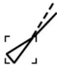 Target selected for data display Target selected for data display | Target selected by use for data display. |
5.3 Setting Number of AIS Targets to Display
Up to 100 of the closest AIS targets may be displayed on the screen. If you do not require all targets you choose the number of targets to display, from 1-100.
- Press the MENU key to display the main menu.
- Press the SYSTEM CONFIGURATION soft key.
- Press the GENERAL SETUP soft key.
- Press the AIS OPTION soft key to show the AIS OPTION menu.
- Choose THE NUMBER OF AIS TARGET and press the EDIT soft key.
- Enter the number of AIS targets you wish to display and press the ENTER soft key.
- Press the MENU key to close the menu.
5. AIS OPERATION
5.4 Activating Targets
- Use the trackball to place the cursor on the sleeping AIS target (indicates only the presence of a vessel equipped with AIS in a certain location) you wish to activate; that is, know more about a vessel's motion.
- Push the ENTER knob. The activated AIS target symbol is superimposed on the radar echo as below.

Activated target
*1: Vector shows STW (speed thru water) and CSE (course) when water tracking mode is selected at the radar.
*2: If there is no heading data, the line points in direction of COG.
5.5 Displaying Target Data
- Place the cursor on an AIS target symbol.
- Press the ENTER knob to show the target's basic data. The target is marked as below.

natural_image
Pure geometric lines forming a triangle with perpendicular indicators (no text or symbols)Activated target selected for data display

* = CSE (course) when water tracking mode is selected at radar.
= STW (speed thru water) when water tracking mode is selected at radar.
AIS target data display
5.6 Lost Target
A target is declared a lost target when no data is received for three to five reporting intervals. When this occurs, the target is marked with the (flashing) lost target symbol. However, the target which becomes a lost target is a activated target or a sleeping target within the lost target range.

Lost target
Confirming a lost target
- Use the trackball to place the cursor where there is no ARPA target, marks or lines.
- Push the ENTER knob.
5.7 Setting CPA and TCPA
When the predicted CPA of any target becomes smaller than a preset CPA alarm range or its predicted TCPA less than a preset TCPA alarm limit, an audio alarm sounds, the messages CPA ALARM and TCPA ALARM appear, and the speaker icon appears (in red). In addition, the AIS target plot symbol of the offending target changes to a triangle and flashes together with its vector. You may silence the audio alarm with the CLEAR key.
Press the ALARM key and the message “COLLISION ALARM” appears. Press the CLEAR soft key to acknowledge the alarm. The flashing of the triangle plot symbol continues until you intentionally terminate tracking of the target. The ARP continuously monitors the predicted range at the Closest Point of Approach (CPA) and predicted time to CPA (TCPA) of each track to own ship.
This feature helps alert you to targets which may be on a collision course with own ship. However, it is important that gain, A/C SEA, A/C RAIN and other radar controls are properly adjusted and the ARP is set up so that it can track targets effectively.
CPA/TCPA alarm ranges must be set up properly taking into consideration the size, tonnage, speed, turning performance and other characteristics of own ship.
Follow the steps shown below to set the CPA/TCPA alarm range:
- Press the MENU key.
- Press the SYSTEM CONFIGURATION soft key.
- Press the GENERAL SETUP soft key.
- Press the AIS OPTION soft key to show the AIS OPTION menu.
- Choose CPA and then press the EDIT soft key to show the CPA window.
5. AIS OPERATION

CPA window
- Select a CPA limit desired from 0.5 nm, 1 nm, 2 nm, 3 nm, 5 nm and 6 nm with the Trackball.
- Press the ENTER soft key.
- Choose TCPA.
- Press the EDIT soft key to show the TCPA window.

TCPA window
- Select a TCPA limit from 30 sec, 1 min, 2 min, 3 min, 4 min, 5 min, 6 min and 12 min.
- Press the ENTER soft key.
- Press the MENU key to close the menu.
5.8 Proximity Alarm
The proximity alarm alerts when there are AIS targets within the range you set. When an AIS target comes within the proximity alarm range, the message AIS TARGET COMES CLOSE appears.
- Press the MENU key.
- Press the SYSTEM CONFIGURATION soft key.
- Press the GENERAL SETUP soft key.
- Press the AIS OPTION soft key to show the AIS OPTION menu.
- Choose PROXIMITY ALARM and push the ENTER knob.
- Enter proximity alarm range (1-24 nm) and press the ENTER soft key.
- Press the MENU key to close the menu.
5.9 Showing, Hiding AIS Target Tracks
AIS target tracks may be shown or hidden as follows
- Press the MENU key followed by the CHART SETUP and TRACKS & MARKS CONTROL soft keys to open the TRACK CONTROL menu.
- Use the Trackball to select TARGET TRACK DISPLAY.
- Press the EDIT soft key to show the target track display window.
- Use the Trackball to select one of the following: OFF (no ARP nor AIS): Turn off target tracks. ON (ARP and AIS): Turn on target tracks ARP ONLY (ARP equipped): Show only ARP tracks. AIS ONLY (AIS equipped): Show only AIS tracks. BOTH: Show both ARP and AIS tracks.
- Press the ENTER soft key.
- Press the MENU key to close the menu.
5.10 Choosing Vector Time
The vector is the line extending from a tracked target which shows estimated speed and course of the target. The vector tip shows an estimated position of the target after the selected vector time elapses. It can be useful to extend the vector length (time) in order to evaluate the risk of collision with any target.
- Press the MENU key.
- Press the SYSTEM CONFIGURATION soft key.
- Press the GENERAL SETUP soft key.
- Press the AIS OPTION soft key to show the AIS OPTION menu.
- Choose VECTOR TIME and then press the EDIT soft key to show the AIS vector time window.

AIS vector time window
- Operate the Trackball to select vector time among 30 sec, 1 min, 3 min, 6 min, 15 min and 30 min.
- Press the ENTER soft key.
- Press the MENU key to close the menu.
5. AIS OPERATION
5.11 Displaying Past Positions of AIS Targets
You can display time-spaced dots (maximum ten dots) marking the past positions of any AIS targets being tracked. You can evaluate a target's actions by the spacing between dots. Below are examples of dot spacing and target movement.

AIS past position displays
To turn the AIS past position display on or off:
- Press the MENU key to display the main menu.
- Press the SYSTEM CONFIGURATION soft key.
- Press the GENERAL SETUP soft key.
- Press the AIS OPTION soft key to show the AIS OPTION menu.
- Choose HISTORY INTERVAL and then press the EDIT soft key.

History interval window
- Operate the Trackball to select history interval among 30 sec, 1 min, 3 min and 6 min, or select OFF to turn off the past position display.
- Press the ENTER soft key.
- Press the MENU key to close the menu.
This chapter provides information for saving and replaying data to and from memory cards, uploading and downloading data, loading waypoint data from Yeoman, and outputting data through the network.
6.1 Memory Card Operations
The memory cards store these data: marks, lines, waypoints, routes, track, position, water temperature and setting data (plotter only). The following memory cards may be used:
Kingstone: SD-M64B1 (64 MB), SD-M128B1 (128 MB)
Viking: 32SD-M32B1 (32 MB), 64SD-M64B1 (64 MB)
EP Memory: 32 MB, 64 MB
SANDISK: 64SDSDB-64-J60 (64 MB), 128SDSDB-128-J60 (128 MB)
Panasonic: 64 RP-SD064BL1A (64 MB), 128RP-SD128BL1A (128 MB)
Toshiba: 64 SD-NAD064MT (64 MB), 128 SD-NA128MT (128 MB)
6.1.1 Deleting all data (other than chart data) from memory cards
Follow the procedure below to delete all data from a memory card.
- Insert a blank memory card into the card slot.
- Press the MENU key followed by the SYSTEM CONFIGURATION, DATA TRANSFER, UPLOAD/DOWNLOAD DATA and SAVE DATA TO MEMORY CARD soft keys to show the SAVE DATA menu.

* = Plotter data only
Save data menu
- Press the DELETE soft key. You are asked if you are ready to delete the memory card.
- Push the ENTER knob to delete (or press the CLEAR key to escape). Do not remove the card while its contents are being deleted. When the deleting is completed, "COMPLETED DELETING USER DATA. PUSH ENTER KNOB TO CONTINUE." appears.
- Push the ENTER knob to continue.
6. DATA TRANSFER
Note: If the memory card was not inserted correctly, the message "FAILED TO DELETE MEMORY CARD." appears.
6.1.2 Saving data to a memory card
- Insert a formatted memory card into the slot.
- Press the MENU key followed by the CONFIGURATION, DATA TRANSFER, UPLOAD/DOWNLOAD DATA and SAVE DATA TO MEMORY CARD soft keys to show the SAVE DATA menu.
- Use the Trackball to select item to save.
- Press the EDIT soft key.
- Use the Trackball to select ON.
- Press the ENTER soft key.
- Repeat steps 3 to 6 to choose other data to save if desired.
- Press the SAVE soft key, then press the ENTER knob. The message "NOW SAVING DATA TO MEMORY CARD. DO NOT TURN OFF DISPLAY UNIT UNTIL COMPLETED." appears.
When saving is completed, "COMPLETED SAVING DATA. PUSH ENTER KNOB TO CONTINUE." appears. Push the ENTER knob to continue.
Memory card messages
Various memory card messages appear to alert you to memory card-related error. These are tabulated below.
Memory card messages
| Message | Reason | Remedy |
| Memory card is not inserted. Please insert memory card. Push ENTER knob to continue. | Memory card not inserted. | Push the ENTER knob to return to the SAVE DATA display and then insert card. |
| Overwrite data? (Track) (Mark) (WPT) (Config) | Data type to be recorded exists on memory card. (Two or more of same type of data cannot be recorded.) | Push the ENTER knob to overwrite same data type on the card, or press the CLEAR key to escape. |
| Failed to save data. Push ENTER knob to continue. | Could not save data. | Push the ENTER knob to continue. |
6.1.3 Playing back data from a memory card
Data (track, marks, lines, waypoints, routes and setting data) can be loaded from a memory card and displayed on the screen. This feature is useful for observing past data and setting up the equipment for a specific purpose with “setting data.”
- Press the MENU key followed by the SYSTEM CONFIGURATION and DATA TRANSFER soft keys.
- Press the UPLOAD/DOWNLOAD DATA soft key.
- Press the LOAD DATA FROM MEMORY CARD soft key to show the LOAD DATA menu.

Load data menu
- Use the Trackball to select item to load.
- Press the EDIT soft key. (The EDIT soft key is inoperative when no memory card is inserted or there is no data in the memory card.)
- Use the Trackball to select ON. (Select OFF not to load selected data.) Press the ENTER soft key. If the memory card does not contain the item selected, the unit beeps and ON cannot be selected.
- After selecting all items desired, press the LOAD soft key, then press the ENTER knob. The message "NOW LOADING FROM MEMORY CARD." appears.
- After loading is completed, the message "COMPLETED LOADING DATA. PUSH ENTER KNOB TO CONTINUE." appears. Push the ENTER knob to continue.
Notes on loading data
Tracks: Since loaded track data is added to internal track, oldest track will be erased when the track memory capacity is exceeded.
Waypoints & routes: The loaded data replaces like stored data.
Marks & lines: The loaded data is added to internal data. When the mark/line memory becomes full no marks may be entered.
Setting data: The loaded data replaces current configuration settings. If the memory card contents could not be loaded, push the ENTER knob to restart with default settings. Note that track memory capacity is not saved or loaded. To use loaded setting data, turn the power off and on again.
Wallpaper: Load desired wallpaper. (See Chapter 7.)
6.2 Uploading, Downloading Data
You can upload/download waypoints, routes, marks and lines from/to a PC, through the DATA 4 port at the rear of the display unit. Note that radar and sounder data cannot be uploaded or downloaded.
6.2.1 Setting communication software on the PC
The communication format (RS-232C) with the PC is as follows:
Baud Rate: 4800 bps
Character Length: 8 bits
Stop bit: 1 bit
Parity: None
X Control: XON/XOFF (fixed)
The following data can be downloaded/uploaded between a PC and this equipment:
Waypoint data (In alphanumeric order)
Route data (In order of route number)
End of sentence
Note 1: There are two kinds of data for route data: route data and route comment data.
Note 2: DGPS position fix is not available when uploading or downloading data.
Note 3: Wiring information appears on the UPLOAD or DOWNLOAD menu.
6.2.2 Uploading or downloading data
- Connect the PC to the equipment.
- Press the MENU key to show the main menu.
- Press the SYSTEM CONFIGURATION soft key.
- Press the DATA TRANSFER soft key.
- Press the UPLOAD/DOWNLOAD DATA soft key.
- Press the DOWNLOAD WPT/ROUTE TO PC or UPLOAD WPT/ROUTE FROM PC soft key.

Baud rate window
8. Select baud rate, then press the ENTER soft key. 9. Press the DWLOAD or UPLOAD soft key. You are asked if you are ready to download or upload waypoints and routes. 10. Push the ENTER knob to download (upload).Waypoint data format
Waypoint data format
1: Waypoint latitude 2: N/S 3: Waypoint longitude 4: E/W 5: Waypoint name (Number of characters is fixed to 6 and space code is placed when the number of characters are less than 6.) 6: Waypoint color 7: Waypoint comment (1 byte for mark code + 13 characters of comment.) 1st byte of mark code: Fixed to "@". 2nd byte of mark code: Internal mark code. See Note 1. 8. Information of marking waypoint. Always set to "A". "A": Displayed "V": Not displayed Note 1: The following characters can be used for comments:  Characters available for commentRoute data menu
Route data format
1: Number of sentences required for one complete route data (1 to 4). See Note 2. 2: Number of sentences currently used (1 to 4) 3: Message mode (Always set to C) 4: Route No. (001 to 300, 3 digits required) 5 through 12: Waypoint name (Max. 8 names, length of each waypoint name is fixed to 7 byte) Note 2: A route can may contain 35 waypoints, and the GPRTE sentence for one route data may exceed 80 byte limitation. In this case, route data is divided into several GPRTE sentences (Max. 4 sentences). This value shows the number of sentences the route data has been divided.Route comment data format
Route comment format
1: Route No. (01 to 200, 3 digits required) 2: Route comment (Max. 16 characters, variable length) The same characters of the comment for waypoint comment can be used.End of sentence
\$PFEC, GPxfr, CTL, EMark data format
$PFEC, GPmrk, xxxxxxxx, xxxxxxxx, xxxxxxxx, x, x, x, xxxxxxxx, c----c<CR><LF>
Mark data format
1: Geodetic latitude (Latitude in minutes, hexadecimal) 2: Longitude (longitude in minutes, hexadecimal) 3: Mercator latitude (latitude in minutes, hexadecimal) 4: Mark code 5: Color (0: black, 1: red, 2: yellow, 3: green, 4: light-blue, 5: purple, 6: blue, 7: white) 6: Status (hexadecimal number) (b0: (0/1)=mark/line), b1: (0/1)=(memory/replay) b2: reserve b3: External event (0/1)=(no/YES), b4: Line connection (=1: connect to the previous) b [5, 6]: Line type 7: Time entered (Hexadecimal number, total seconds from 1986/1/1 00:00:00 as reference) 8: Comment (Max. 15 characters, including the code not required for NMEA)6.3 Loading Waypoint Data from Yeoman
Waypoint data can be loaded from a Yeoman to this equipment. Connect the Yeoman to a DATA port on this equipment and then follow the procedure below. 1. Press the MENU key. 2. Press the SYSTEM CONFIGURATION key. 3. Press the DATA TRANSFER soft key. 4. Press the RECEIVE YEOMAN DATA soft key. 5. You are asked if you are sure to receive waypoint data from Yeoman equipment. Push the ENTER knob to receive the data. The message "NOW RECEIVING YEOMAN DATA. PUSH SOFT KEY 'STOP' TO STOP RECEIVING." Is displayed. If waypoint capacity is reached the message "WAYPOINTS FULL. NO MORE WAYPOINT CAN BE RECEIVED. PUSH ANY KEY TO STOP." appears. To stop receiving, press the STOP soft key. After waypoints have been received, press the MENU key.6. DATA TRANSFER
6.4 Receiving Data Via Network Equipment
You can receive waypoints, routes, marks and lines from NavNet equipment. 1. Press the MENU key. 2. Press the SYSTEM CONFIGURATION soft key. 3. Press the DATA TRANSFER soft key. 4. Press the RECEIVE DATA VIA NETWORK soft key.  Receive data menu 5. Select HOST NAME, then press the EDIT soft key.  Host name window 6. Use the Trackball to choose host name from which to receive data, then push the ENTER knob. 7. Select the data you wish to receive, then press the EDIT soft key. For example, select MARKS & LINES.  Marks & lines window 8. Select ON or OFF as appropriate, then press the ENTER soft key. 9. Turn WAYPOINTS & ROUTES on or off as appropriate. 10. Press the RCV soft key followed by the ENTER knob. The message "NOW RECEIVING DATA." is displayed. If no data could be found, the message "(HOST NAME)" IS NOT FOUND." appears. When the transfer is completed, the message "DATA TRANSFER COMPLETED. PUSH ENTER KNOB TO CONTINUE." appears. Push the ENTER knob to finish. 11. Press the MENU key to close the menu.6.5 Outputting Data Through the Network
Follow the procedure below to output data through the network. To prevent trouble, do not output the same data from multiple sources. 1. Press the MENU key to open the menu. 2. Press the SYSTEM CONFIGURATION, SYSTEM SETUP, PORT SETUP and OUTPUT THROUGH NETWORK soft keys.  Select sentence menu 3. Select sentence with the Trackball. 4. Press the ON/OFF soft key to turn sentence on or off. 5. Press the RETURN soft key. 6. Press the MENU key to close the menu. AAM: Waypoint arrival alarm APB: Autopilot sentence B BOD: Bearing origin to destination BWR: Bearing and distance to waypoint - rhumb line DPT: Depth GGA: Global positioning system(GPS) fix data GLL: Geographic position - latitude/longitude GTD: Own ship information-TD MTW: Water temperature RMA: Recommended minimum specific LORAN-C data RMB: Recommended minimum navigation information RMC: Recommended minimum specific GPS/TRANSIT data VHW: Water speed and heading VTG: Course over ground and ground speed WPL: Waypoint location XTE: Cross-track error, measured ZDA: Time and date HDT: Heading true, HDG: Heading, deviation and variation MWV: Wind speed and angle6. DATA TRANSFER
This page intentionally left blank.7. CUSTOMIZING YOUR UNIT
This chapter describes the various options which allow you to set up your unit to suit your needs. For mode-specific menus, e.g. radar, plotter and sounder, make sure that you select the appropriate display when making changes or viewing menu options.7.1 General Setup
This paragraph shows you how to set up functions common to the plotter, radar and sounder displays. This is done on the GENERAL SETUP menu, which you may display from any mode. These items include language, key beep, units of measurement, data sources, etc. 1. Press the MENU key to display the main menu. 2. Press the SYSTEM CONFIGURATION soft key. 3. Press the GENERAL SETUP soft key.  Page 1  Page 2General setup menu
4. Press the NEXT PAGE or PREV. PAGE soft key to switch pages if necessary. 5. Use the Trackball to select item. 6. Press the EDIT soft key. 7. Use the Trackball to select option desired, then press the ENTER soft key. 8. Press the MENU key to close the menu. Contents of general setup menu| Item | Description | Settings |
| Key Beep Turns key beep on/off. On, Off | ||
| Language Chooses menu language. English, French, German, Italian, Portuguese, Spanish, Danish, Swedish, Norwegian | ||
| Range Unit Chooses unit of range and speed measurement. | nm, kt; km, km/h; sm, mph; nm & yd, kt; nm & m, kt; km & m, km/h; sm & yd, mph | |
| Temperature Unit Chooses unit of water temperature measurement. | °C, °F | |
| Depth Unit Chooses unit of depth measurement. m, ft, fa, P/B (Passi/Braza) | ||
| Wind Unit Chooses unit of wind measurement. Kt, km/h, MPH, m/s | ||
| Wind Data Chooses how to display wind data. | Apparent: The wind felt aboard a moving vessel. It is the combination of the true wind and the boat wind. True: The true speed and direction of the wind, not modified by the effects of the boat's movement. | |
| Speed Averaging Calculation of ETA is based on average ship's speed over a given period. If the period is too long or too short, calculation error will result. Change this setting if calculation error occurs. The default setting is suitable for most conditions. | 0-9999 seconds | |
| Local Time Offset Enter time difference between local time and UTC time to use local time. | -13:30 to +13:30 | |
| Reset Trip Log Resets trip log. Yes, No | ||
| Timeout Display Setting Sets number of seconds to show a window (for example, BRILL, GAIN) before it is erased from the screen. | 15 s, 30 s, 60 s, Continue (no timeout) | |
| Save MOB Key Function Defines the function of the SAVE/MOB key. | Save Ship Position & MOB: Short press to save ship position, long press to save MOB. MOB Without Confirmation: Position saved as MOB position without confirmation. This setting is only effective with automatic range selection and with waypoint marker displayed on radar display. Quick Point Function: Position saved as quick point. | |
| Wallpaper Chooses what to display in menu background. Requirements for user wallpaper Size: 252 KB or less, 640(H)x480(V) Name: wallpaperh.png No. of Colors: 256 Compression Level: None Interlace: None Permeation Color: None | Default: Default wallpaper User: User wallpaper. To use your own wallpaper, save Microsoft Photo Editor or Adobe Photoshop created png image (see conditions at left) to SD card, load file to equipment (see Chapter 6) and then choose this User option. | |
| Lat/Lon Display Chooses how many digits (or seconds) to display after decimal point in latitude and longitude position. | DD°MM.MM', DD°MM.MMM', DD°MM.MMMM', DD°MM'SS.S" | |
| Item | Description | Settings |
| TD Display Chooses type of TD to display. | Loran C, Decca | |
| Speed Chooses speed format to display. SOG (Speed over ground), STW (Speed through water) | ||
| Position Display | Chooses how to display position.Examples of MGRS indications:18S: Locating a point within the Grid Zone Designation18SUU: Locating a point within a 100,000-meter square18SUU80: Locating a point within a 10,000-meter square18SUU8401: Locating a point within a 1,000-meter square18SUU836014: Locating a point within a 100-meter square | Latitude, Longitude; Loran or Decca TDs, or MGRS (Military Grid Reference System).What is MGRS?For convenience, the world is generally divided into 6^ by 8^ geographic areas, each of which is given a unique identification, called the Grid Zone Designation. These areas are covered by a pattern of 100,000-meter squares. Each square is identified by two letters called tie 100,000-meter square identification. This identification is unique within the area covered by the Grid Zone Designation. Exceptions to this general rule have been made in the post to preserve the 100,000-meter identifications on mapping that already exists.A reference keyed to a gridded map of any scale is made by giving the 100,000-meter square identification together with the numerical location. Numerical references within the 100,000-mater square are given to the desired accuracy in terms of the easting (E) and northing (N) grid coordinates for the point. The Grid Zone Designation usually is prefixed to the identification when references are made in more than one grid zone designation area. |
| Time Display | Chooses time notation. 12 hours, 24 hours | |
| Infrared Remote Mode | A remote controller can be set exclusively for use with a specific display unit, in the case of multiple NavNet display units. For further details see the Installation Manual. | A, B, C, D |
7. CUSTOMIZING YOUR UNIT
Contents of general setup menu (con't from previous page)| Item | Description | Settings |
| Range & Bearing Mode | Chooses how to calculate range and bearing. | Great Circle: Shortest course between two points on the surface of the earth.Rhumb Line: Straight line drawn between two points on a nautical chart. |
| Bearing Readout | Chooses bearing display format for course, course over ground and cursor bearing. | True, Magnetic |
| Magnetic Variation | The magnetic variations for all areas of the earth are preprogrammed into this unit. The preprogrammed variation is accurate for most instances, however you may wish to manually enter a variation. For manual input, select Manual, hit the EDIT soft key, enter value, then hit the ENTER soft key to set. “AUTO” requires position data. | Auto, Manual |
7.2 Radar Setup
This paragraph explains how to customize the radar display to suit your operational needs.7.2.1 Radar display setup
The radar display may be set up from the RADAR DISPLAY SETUP menu, which contains items such as EBL reference and cursor position format. 1. Press the MENU key to show the main menu. 2. Press the RADAR DISPLAY SETUP soft key.  Radar display setup menu Contents of radar display setup menu| Item | Description Settings | |
| EBL Reference | References EBL bearing, shown in the EBL data box, to North (True) or heading (Relative). Relative with no heading input. True only in course-up, north-up and true motion. | True, Relative |
| Cursor Position | Chooses how to display cursor position.Note: “RNG & BRG-TRUE” requires heading data, true bearing. Reverts to relative bearing when heading data is lost. | LAT/LON: Lat/Long position of cursor TD: Loran C or Decca TDs RNG & BRG-REL: Range and bearing in relative bearing.RNG & BRG-TRUE: Range and bearing in true bearing.MGRS: MGRS format position |
| Tuning Selects | Receiver tuning method. For further details see the paragraph “2.3 Tuning.” | Auto, Manual |
| TX Sector Blanking | Turns on/off dead sector graphic, which shows area where no echoes are received. To set sector, select ON, then enter range. Max. sector is 135°. Dashed lines mark the dead sector. Note that noise may occasionally appear in the TX sector when the echo trail feature is turned on.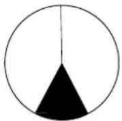 Dead sector Dead sector | On, Off |
| Noise Rejection | Electrical noise, appearing on the screen as “speckles,” may be suppressed with the noise rejector. Note that some forms of interference cannot be suppressed. | Off, Low, High |
| Item | Description Settings | |
| Background Color | Chooses colors of background, range rings and characters. Effective when HUE soft key is set for MANUAL SET. | Black/GreenBackground: BlackRings: GreenCharacters: GreenBlack/RedBackground: BlackRings: GreenCharacters: RedBlue/WhiteBackground: BlueRings: WhiteCharacters: WhiteDK Blue/WhiteBackground: Dark BlueRings: GreenCharacters: RedWhite/GreenBackground: WhiteRings: GreenCharacters: Green |
| Echo Color | Chooses echo color. | Yellow, Green, Multi-color. (Multi-color shows echoes in red, yellow or green in order of descending strength.) |
| 2ND Echo Rejection | Reduces second-trace echoes. See the paragraph “2.24 Suppressing Second-trace Echoes.” | On, Off |
| Watchman Time | Sets watchman stand-by period. For further details see the paragraph “ 2.23 Watchman.” | 5, 10, 20 minutes |
| Range Unit Select unit of range measurement. nm, km, sm | ||
| Trail Mode | Sets echo trail reference.Note: Relative trail is available in all presentation modes except true motion. True trail is available in all modes. | True: Echo trails plotted in actual courses and speeds. Requires compass signal and speed input.Relative: Echo trails move relative to own ship. |
7.2.2 Radar range setup
You may choose the radar ranges you wish to use, from the RADAR RANGE SETUP menu. After choosing the ranges desired, change the range with the RANGE key to activate range settings. Available ranges depends on the radar used. At least two ranges must be turned on. When less than two ranges are turned on you cannot escape from the RADAR RANGE SETUP menu. Note that this function is not available with the GD-1920C. 1. Press the MENU key to show the main menu. 2. Press the RADAR RANGE SETUP soft key to show the RADAR RANGE SETUP menu.  \* = Max. range depends on network radar used and is set on the network radar at installation. Range unit: nm  Range unit: kmRadar range setup menu
3. Use the Trackball to select the range which you want to turn on or off. 4. Press the ON/OFF soft key to turn a range on or off as appropriate. 5. Press the RETURN soft key to register settings. 6. Press the MENU key to close the menu.| Model | Maximum |
| 1824C 24 nm, km, sm | |
| 1834C 36 nm, km, sm | |
| 1934C 48 nm, km, sm | |
| 1944C 64 nm, km, sm | |
| 1954C, 1964C 72 nm, | km, sm |
7. CUSTOMIZING YOUR UNIT
7.2.3 Function key setup
The function keys provide one-touch execution of a desired function. The default radar function key settings are as shown in the table below.| Function Key Default Function Function Key Label | ||
| 1 Turn heading line off. HL | ||
| 2 Turn range rings on/off. RNG | ||
| 3 Turn echo trail on/off. TRL | ||
| 4 Turn display offcenter on/off. OFC | ||
| 5 | STBY/TX | TX |
flowchart
graph TD
    A["Function key setting"] --> B["SOFT KEY 1"]
    A --> C["Function key label"]
    B --> D["HL: HDG LINE OFF"]
    C --> E["SOFT KEY 2"]
    E --> F["RNG: RINGS ON/OFF"]
    F --> G["RNG"]
    G --> H["SOFT KEY 3"]
    H --> I["TRL: ECHO TRIAL"]
    I --> J["TRL"]
    J --> K["SOFT KEY 4"]
    K --> L["OFC: OFFCENTER"]
    L --> M["OFC"]
    M --> N["SOFT KEY 5"]
    N --> O["TX: STBY/TX"]
    O --> P["TX"]
    P --> Q["FUNC KEY"]
    Q --> R["EDIT"]
    Q --> S["RETURN"]
flowchart
graph LR
    A["SOFT KEY 1"] -->|Scroll down| B["SOFT KEY 1"]
    B -->|Scroll down| C["SOFT KEY 1"]

    subgraph A
        A1["OFF"]
        A2["HL: HDG LINE OFF"]
        A3["MOD: MODE"]
        A4["GAI: GAIN"]
        A5["SEA: A/C SEA"]
        A6["RAI: A/C RAIN"]
        A7["FTC: FTC"]
        A8["ES: ECHO STRETCH"]
        A9["PLS: PULSE LENGTH"]
        A10["ZOM: ZOOM"]
    end

    subgraph B
        B1["OFC: OFFCENTER"]
        B2["TRL: ECHO TRAIL"]
        B3["RNG: RINGS ON/OFF"]
        B4["TLL: TLL OUTPUT"]
        B5["ALM: GUARD ALARM"]
        B6["EBL: EBL"]
        B7["VRM: VRM"]
        B8["TTM: TTM ON/OFF"]
        B9["WMK: WPT ON/OFF"]
        B10["WTM: WATCHMAN"]
    end

    subgraph C
        C1["ACQ: ACQUISITION"]
        C2["TX: STBY/TX"]
        C3["RSR: SOURCE RADAR"]
        C4["DBX: D. BOX ON/OFF"]
        C5["CHG: CHANGE CNTRL"]
        C6["QP: QUICK POINT"]
        C7["MRK: MARK ENTRY"]
    end
| Menu Item Function | Function Key Label | |
| OFF Assigns no function. — | ||
| HL: HDG LINE OFF Turns heading line off. HL | ||
| MOD: MODE Selects presentation mode. MOD | ||
| GAI: GAIN Shows gain sensitivity adjustment window. GAI | ||
| SEA: A/C SEA Shows A/C SEA adjustment window. SEA | ||
| RAI: A/C RAIN Shows A/C RAIN adjustment window. RAI | ||
| FTC: FTC | Displays FTC window. Available with Model 1700 series radar. Inoperative otherwise. | FTC |
| ES: ECHO STRETCH | Turns echo stretch on/off. | ES |
| PLS: PULSE LENGTH | Sets pulselength (long or short). | PLS |
| ZOM: ZOOM | Turns zoom on/off. | ZOM |
| OFC: OFFCENTER | Press to shift display center to cursor location. Press again to turn shift off and return cursor to display center. | OFC |
| TRL: ECHO TRAIL | Starts/stops echo trails. | TRL |
| RNG: RINGS ON/OFF | Turns range rings on/off. | RNG |
| TLL: TLL OUTPUT | Outputs cursor position, in NMEA format, to navigator. | TLL |
| ALM: GUARD ALARM | Displays alarm soft keys. | ALM |
| EBL: EBL | Switches control between EBL1 and EBL2 with each press. | EBL |
| VRM: VRM | Switches control between VRM1 and VRM2 with each press. | VRM |
| TTM: TTM ON/OFF | Turns TTM (Tracked Target Message) display on/off. | TTM |
| WMK: WPT ON/OFF | Turns waypoint marker on/off. | WMK |
| WTM: WATCHMAN Turns watchman on/off. WTM | ||
| ACQ: ACQUISITION | Acquires and tracks cursor-selected target. (Requires ARP-equipped Model 18x4/19x4 series network radar.) | ACQ |
| TX: STBY/TX | Toggles between standby and transmit | TX |
| RSR: RADAR SOURCE | Selects source for radar picture. | RSR |
| DBX: D. BOX ON/OFF | Turns data boxes on/off. | DBX |
| CHG: CHANGE CNTRL | Changes display control in combination display. | CHG |
| QP: QUICK POINT | Sets quick point (for navigation). | QP |
| MRK: MARK ENTRY | Enters the mark at the cursor position. | MRK |
7. CUSTOMIZING YOUR UNIT
7.3 Plotter Setup
This paragraph provides the information necessary for setting up the plotter display.7.3.1 Navigation options
Navigation options, for example, waypoint switching method, may be set on the PLOTTER SETUP menu. 1. Show the plotter display, then press the MENU key open the main menu. 2. Press the PLOTTER SETUP soft key.  Plotter setup menu Contents of plotter setup menu| Item | Description | Settings |
| Waypoint Switching | Chooses waypoint switching method. See “switching waypoints” on page 3-45. | Perpendicular, Arrvl Alm Crcl, Manual |
| Course Vector | You may extend a line from the own ship position to show ship’s course. It may be a vector (length depends on ship’s speed) or a simple line (course bar). | Line, Vector, Off |
| Set GOTO Method | Sets the method by which to navigate to a quick point. See “3.10.1 Navigating to a quick point.” | 1 Point, 35 Points, 35 Pts/Port Service |
| QP | Set “EXT WPT (RMB)” when a destination waypoint is displayed from a external navigation equipment. | EXT WPT (RMB), Internal |
| Safe Route Check (C-MAP only) | The safe route check feature checks for interfering objects (such as wrecks) within a route when creating or editing a route. | On, Off |
| Popup Info | You may show the information for objects as below.ALL ON: When the cursor is placed on anywhere on chart, the information for that location appears.POINTS ON: When the cursor is placed on an object symbol, the information for it appears.OFF: No information appears. | ALL ON, POINTS ON, OFF |
| QPT/MARK SOFT KEY | Chooses the function of the uppermost soft key on the plotter display between QUICK POINT and MARK ENTRY. QUICK POINT: Enters the quick point at the cursor or own ship position.MARK ENTRY: Enters the mark at the cursor or own ship position. | QUICK POINT, MARK ENTRY |
| D. BOX (soft key) | Sets up data boxes. See paragraph 7.5. |
7.3.2 Function key setup
The function keys provide one-touch execution of a desired function. The default plotter function key settings are as shown in the table below.| Function Key | Default Function | Function Key Label |
| 1 Start/stop | recording/plotting own ship's track. TRK | |
| 2 | Edit mark/line. EML | |
| 3 Ruler (measure range and bearing between two points). RUL | ||
| 4 | Add new waypoint. | ADD |
| 5 | Alphanumeric waypoint list. | ALP |
7. CUSTOMIZING YOUR UNIT
4. Select function desired with the Trackball, then press the ENTER soft key or ENTER knob to register your selection. 5. Press the MENU key to close the menu. Plotter function keys| Menu Item Function | Function Key Label | |
| OFF Assigns no function. — | ||
| ADD: ADD NEW WPT Registers waypoint at cursor position. Place cursor for waypoint location, then press function key. | ADD | |
| MWP: MOVE WPT Moves selected waypoint to different position.Select waypoint, press function key, select new position, then press the ENTER knob. | MWP | |
| RUL: RULER Measures range and bearing between two points.Press START POINT soft key to change starting point if necessary. Range and bearing between two points appears at the top of the screen. | RUL | |
| GWP: GOTO WPT Specify waypoint to set as destination. Enter waypoint name in window, then press the ENTER soft key. | GWP | |
| GRT: GOTO ROUTE Specify route to follow. Enter route name in window, then press the ENTER soft key. | GRT | |
| EML: EDIT MK/LINE Displays mark & line menu. Press appropriate soft key to access menu item. | EML | |
| TRK: TRACK ON/OFF Each press starts or stops recording/plotting own ship's track. | TRK | |
| TTM: TTM ON/OFF Turns TTM (target track) display on/off. | TTM | |
| DTT: DEL TGT TRACK Erases all TTM track. | DTT | |
| ALP: ALPHA LIST Displays waypoint alphanumeric list. | ALP | |
| LCL: LOCAL LIST Displays waypoint local list. | LCL | |
| RTE: ROUTE LIST Displays route list. | RTE | |
| DBX: D. BOX ON/OFF Shows/hides data boxes. | DBX | |
| CHG: CHANGE CNTRL Changes control in combination screen. | CHG | |
| QP: QUICK POINT Sets quick point (for navigation). QP | ||
| MRK: MARK ENTRY Enters the mark at the cursor position. | MRK | |
7.4 Chart Setup
This paragraph shows you how to setup digital charts, from offsetting chart position to turning chart attributes on or off.7.4.1 Chart offset
In some instances position may be off by a few seconds. For example, the position of the ship is shown to be at sea while it is in fact moored at a pier. You can compensate for this error by offsetting chart position as shown in the procedure below. 1. Show the plotter display, then press the MENU key followed by the CHART SETUP and CHART OFFSET soft keys.  Plotter display, chart offset selected 2. Use the Trackball to place the cursor at the correct latitude and longitude position of own ship. 3. Press the SET OFFSET soft key. 4. Press the MENU key to close the menu. The "chart offset icon" (☐) appears at the top of the display. To cancel chart offset, press the RESET OFFSET soft key at step 3 in the above procedure.7. CUSTOMIZING YOUR UNIT
7.4.2 Navionics GOLD chart attributes
Navionics GOLD chart attributes may be turned on or off from the CHART DETAILS menu, which you may display as follows: 1. Press the MENU key. 2. Press the CHART SETUP and CHART DETAILS soft keys.  Page 1  Page 2 \*: For FURUNO chart only. Chart details menu (Navionics GOLD) Contents of chart details menu (Navionics GOLD)| Item | Description | Settings |
| Lat/Lon Grid | Latitude and longitude grids | Red, yellow, green, light-blue, purple, blue, white, Off |
| Text Information | Geographic place, name | On, Off |
| Waypoints | Waypoint size | Large, Small, Off |
| Waypoint Names | Waypoint name | On, Off |
| Chart Border Lines Border lines (indices) On, Off | ||
| Light Sector Info Lighthouse viewing sector On, Off | ||
| Object Information | Map data | Off, All On (display area data for cursor-selected object), Points On (display only point data for cursor-selected object) |
| Chart Display | Choose level of detail for map Detailed, Simple | |
| Navaids Symbol Choose what kind of navaids symbols to display. | International, US | |
| Caution & Routing Data | Turn caution and routing data on or off. | On, Off |
| Item | Description | Settings |
| Marine Features Turn | marine features on or off. On, Off | |
| Land Features Turn land features on or off. On, Off | ||
| CONTOUR LINE Soft key | ||
| Spot Soundings Turn water depth display on or off. On, Off | ||
| Safe Contour Shading | Paint areas in dark blue (default color) which are shallower than depth value set. | 2m (or equivalent ft, fa or PB)5 m (or equivalent ft, fa or PB)10 m (or equivalent ft, fa or PB)20 m or equivalent ft, fa or PB) |
| Depth Contour Display depth contours. ALL: Display all depth contours | 5 m: Display only 5 m* depth contours10 m: Display only 10 m* depth contours.20 m: Display only 20 m* depth contoursOFF: Turn off depth contours.* Or equivalent ft, fa or PB. | |
7.4.3 C-MAP chart attributes
Displaying the CHART DETAILS menu
C-MAP chart attributes may be turned on or off from the CHART DETAILS menu: 1. Press the MENU key. 2. Press the CHART SETUP and CHART DETAILS soft keys.  Page 1  Page 2 Chart details menu (C-MAP)CHART DETAILS menu description
CHART DETAILS menu description| Object | Content | Settings | Description |
| display on/off | ON Turns perspective display on. PERSPECTIVE Perspective display off. | ||
| OFF Turns perspective display off. | |||
| DE-CLUTTER | Overlapping object on/off | ON Removes overlapping objects from display. | |
| OFF Displays overlapping objects. | |||
| CHART DISPLAY MODE | Choose chart display mode | FULL All chart attributes are displayed. | |
| SIMPLE Some attributes such as SEABED TYPE, TRACKS and ROUTES are displayed. | |||
| FISHING Setting for use in fishing. | |||
| LOW Only NAV AIDS and water depth are shown. | |||
| CUSTOM User chooses which chart attributes to turn on or off. | |||
| SAFETY STATUS*1 | Safety status indication | ON Safety status ON (See Safety Status Indication on page 7-18 for description.) | |
| OFF Safety status OFF | |||
| WAYPOINT | Waypoints marks and waypoint names | PLOT/OVERLAY Shown on plotter and overlay displays. | |
| PLOT Shown on plotter display. | |||
| OFF Waypoint markers and waypoint names are turned off. Waypoint names are not displayed regardless if WAYPOINT NAME (below) is set to ON. | |||
| WAYPOINT NAME | Waypoint names | PLOTTER/OVERLAY | Shown on plotter and overlay displays. |
| PLOT Shown on plotter display. | |||
| OFF Waypoint names are turned off. | |||
| NAMES Text for land and sea areas | PLOTTER/OVERLAY | Shown on plotter and overlay displays. | |
| PLOT Shown on plotter display. | |||
| OFF Names are turned off. | |||
| BUOYS NAME | Name of buoys | PLOTTEROVERLAY | Shown on plotter and overlay displays. |
| PLOT Shown on plotter display. | |||
| OFF Buoy names are turned off. | |||
| NAV-AIDS | Lighthouses, buoys, etc. | US | NOAA symbols are shown. |
| US SIMPLE | Complex object shown with single icon. | ||
| INT | International symbols are shown. | ||
| INT SIMPLE | Complex object shown with single icon. | ||
| PLOTTER/OVERLAY | Shown on plotter and overlay displays. | ||
| PLOT Shown on plotter display. | |||
| OFF Navaids are turned off. | |||
| LIGHT SECTORS | Light sector | ON | Light sectors displayed. |
| FLASHING | Light sectors displayed and flashing. | ||
| Object | Content | Setting | Description |
| ATTENTION AREAS | Attention areas | PLOTTER/OVER LAY | Shown on plotter and overlay displays. |
| PLOT Shown on plotter display. | |||
| OFF Attention areas are turned off. | |||
| TIDES & CURRENTS | Tidal station and current station | PLOTTER/OVER LAY | Shown on plotter and overlay displays. |
| PLOT Shown on plotter display. | |||
| OFF Tidal station and current station are not shown. Tidal graph is also turned off. | |||
| SEABED TYPE Seabed type | PLOTTER/OVER LAY | Shown on plotter and overlay displays. | |
| PLOT Shown on plotter display. | |||
| OFF Tidal station and current station are not shown. Tidal graph is also turned off. | |||
| PORTS & SERVICES | Ports and services | PLOTTER/OVER LAY | Shown on plotter and overlay displays. |
| PLOT Shown on plotter display. | |||
| OFF Ports and services are not shown.Near Service also not shown. | |||
| TRACKS & ROUTES | Tracks and routes | PLOTTER/OVER LAY | Shown on plotter and overlay displays. |
| PLOT Shown on plotter display. | |||
| OFF Tracks and routes are turned off. | |||
| UNDERWATER OBJECTS | Below-surface obstructions such as wrecks | PLOTTER/OVER LAY | Shown on plotter and overlay displays. |
| PLOT Shown on plotter display. | |||
| OFF Underwater objects are turned off. | |||
| RIVERS & LAKES | Rivers and lakes | PLOTTER/OVER LAY | Shown on plotter and overlay displays. |
| PLOT Shown on plotter display. | |||
| OFF Rivers and lakes are turned off. | |||
| LAND FEATURES | Land features | PLOTTER/OVER LAY | Shown on plotter and overlay displays. |
| PLOT Shown on plotter display. | |||
| OFF Rivers and lakes are turned off. | |||
| LANDMARKS | Landmarks | PLOTTER/OVER LAY | Shown on plotter and overlay displays. |
| PLOT Shown on plotter display. | |||
| OFF Landmarks are turned off. | |||
| LAT/LON GRID Latitude and longitude grids | PLOTTER/OVER LAY | Shown on plotter and overlay displays. | |
| PLOT Shown on plotter display. | |||
| OFF Latitude and longitude grids are turned off. | |||
7. CUSTOMIZING YOUR UNIT
CHART DETAILS menu description (con't from previous page)| Object | Content | Setting | Description |
| CHART BOUNDARIES | Chart boundary lines | ON Shown on plotter and overlay displays. | |
| AUTO Chart border lines are shown for the last four charts in a chart card on the plotter and overlay displays | |||
| PLOTTER/OVER LAY | Chart border lines show on plotter and overlay displays. | ||
| PLOT Chart border lines show on plotter display. | |||
| OFF Chart boundaries are turned off. | |||
| scale to fit whole chart on display | ON Mixing is active. MIXING Changes | ||
| OFF Mixing is disabled. | |||
| chart scale regardless of zoom setting | LOCK Keeps current chart scale. CHART LEVEL Maintains | ||
| UNLOCK | Chart scale may chosen freely. | ||
\*1 SAFETY STATUS INDICATION
The following indications are shown beneath the range indication to denote safety status: NORMAL (or U.ZOOM or O.ZOOM):
This indication appears to help you select a suitable chart scale. NORMAL: Suitable chart scale is selected. U.ZOOM: Chart scale is too small. O.ZOOM: Chart scale is too large. BEST MAP: Shown in red when the unsuitable chart scale is selected. DATA OFF: Mixing levels can be turned on when the electronics chart coverage area does not provide enough coverage to completely fill the display screen. When the cursor or own ship mark is placed in the area with coverage, the chart data is shown as below. On: The chart line in the area with no coverage is shown. This area is filled with dots. Off: The area with no coverage is not shown (goes to white). DECLUT.: For C-MAP MAX charts, symbols of low priority (ex. map symbols on land) can be automatically hidden to unclutter the screen when you change the scale. When the function is turned on, DECLUT. appears in red. DANGERS: Shown in red when the GROUNDING alarm detects the high-risk object (listed in the grounding report) when the GROUNDING alarm is turned on. CAUTIONS: Shown in red when the GROUNDING alarm detects the low-risk object when the GROUNDING alarm is turned on.DEPTH INFO soft key
1. Press the MENU key. 2. Press the CHART SETUP and CHART DETAILS soft keys. 3. Press the DEPTH INFO soft key.  DEPTH INFO menuDEPTH INFO menu description
DEPTH AREAS: Choose the display where to fill in color the depths selected at DEPTH AREAS LIMIT.| Setting | Description | Default | Setting |
| PLOT/OVERLAY | Turns on depth area display on plotter and overlay displays. | PLOTTER | |
| PLOTTER | Turns on depth area display on plotter display. | ||
| OFF | Turns off depth area display. |
| Setting Setting Range Default Setting | ||
| DEPTH AREAS LIMIT-SHALLOW 2 m, | 5 ft, 50 ft, 1 mpb0-49212 ft0-8202 fa, 6 pb | |
| DEPTH AREAS LIMIT-MEDIUM 9 m, 30 ft, 5 fa, 6 pb | ||
| DEPTH AREAS LIMIT-DEEP | 0-9090 pb | 18 m, 60 ft, 10 fa, 11 pb |
7. CUSTOMIZING YOUR UNIT
DEPTH LINES & SOUNDINGS: Choose where to display depth contours, depth data, etc.| Setting | Description | Default | Setting |
| PLOT/OVERLAY | Shows depth lines and soundings on the plotter and overlay displays. | PLOT/OVERLAY | |
| PLOTTER Shows | depth lines and soundings on the plotter display. | ||
| OFF Turns off depth lines and soundings. | |||
| Setting Setting Range Default Setting | ||
| DEPTH LINES AND SOUNDINGS LIMIT-SHALLOW 0 | m,1500 fa, 0 pb0-49212 ft0-8202 fa0-9090 pb | |
| DEPTH LINES AND SOUNDINGS LIMIT-DEEP | 305 m, 1000 ft, 167 fa, 185 pb |
| Setting Setting Range Default Setting | ||
| ROCKS DEPTH LIMIT-SHALLOW 0 m, | 0-800 fa, 0 pb | |
| 0-999 ft | ||
| ROCKS DEPTH LIMIT-DEEP | 0-166 fa | 9 m, 30 ft, 5 fa, 6 pb |
| 0-184 pb |
7.5 Data Boxes Setup
You may select the data to show in the data boxes for the plotter, radar and sounder displays. Six boxes may be displayed in case of small size data box and two for large size data box. 1. Display the radar, plotter or sounder display, whichever you want to set. 2. Press the MENU key to open the main menu. 3. Press one of the following sets of soft keys depending on the display selected at step 1. Plotter mode: PLOTTER SETUP, D. BOX Radar mode: RADAR DISPLAY SETUP, D. BOX Sounder mode: SOUNDER MENU, D. BOX  Data box menu 4. Use the Trackball to select an item, then press the EDIT soft key. 5. Select ON or OFF as desired. 6. Press the ENTER soft key or the ENTER knob to register your selection. Six items may be set to ON for small data boxes; two for large data boxes. 7. Repeat steps 4-6 to turn other items on or off. 8. Press the MENU key to close the menu.7. CUSTOMIZING YOUR UNIT
7.6 Hot Page Setup
Six user-arrangeable hot pages are provided for quick selection of desired display. If the default hot pages are not to your liking you may change them as shown below. 1. Press the MENU key followed by pressing the SYSTEM CONFIGURATION, SYSTEM SETUP, HOT PAGE & NAV DISP SETUP and HOT PAGE SETUP soft keys in that order. 2. Use the Trackball to select the hot page number to set, then press the EDIT soft key. The "SELECT SCREEN TYPE" window appears.  Hot page setup menu 3. Use the Trackball to select screen type desired among FULL SCREEN, SPLIT X 2 and SPLIT X 3 and push the ENTER knob. 4. For the full-screen display, rotate the ENTER knob to select screen desired, then press the ENTER knob. If you selected a split screen, for example, SPLIT X 3, the display now looks as in the figure below.  Hot page setup menu, SPLIT X 3 screen, main screen selection 5. Rotate the ENTER knob to select a main screen, then press the ENTER knob. For example, select the radar display. Your choice is then shaded to show that is has been selected.  Hot page setup menu, SPLIT X 3 screen, sub screen selection 6. Rotate the ENTER knob to select the screen to show at the top right 1/4 screen, then press the ENTER knob or the ENTER soft key. 7. Rotate the ENTER knob to select the screen to show at the bottom right 1/4 screen, then press ENTER knob or the ENTER soft key. Note: The SELECT WINDOW soft key functions to select the window to process. 8. Press the MENU key to close the menu.7.7 Navigator Setup
This section provides the information necessary for selecting the type of navigator connected to your plotter.7.7.1 Navigation data source
The NAV SETUP menu mainly selects the source of nav data. For GPS receiver other than the GP-310B/320B, speed averaging and local time offset (to use local time) are also available. Press the MENU key followed by the SYSTEM CONFIGURATION, NAV OPTION and NAV SOURCE SETTINGS soft keys to display this menu.  Contents of nav setup menu| Item | Description Settings | |
| Position Source | Chooses source of position data. Note: When FURUNO BB GPS is selected, GGA, VTG and ZDA sentences are set to ON automatically. | FURUNO BB GPS: GPS Receiver GP-310B/320B GP: GPS navigator (via NETWORK or NMEA port) LC: Loran C navigator (via NETWORK or NMEA port) ALL: Multiple navaid connection (via NETWORK or NMEA port) |
| Speed Source | Chooses source of speed data ETR (NavNet sounder), NMEA | |
| Temperature Source | Chooses source of water temperature data. ETR, NMEA. Select ETR to show water temperature data fed from the network sounder. | |
| Depth Source | Chooses source of depth data. ETR (NavNet sounder), NMEA | |
| STW Calibration | Calibrates NMEA speed data. Enter amount in percentage. | -50 to +50% |
| Temp Calibration | Calibrates NMEA temperature data. Enter offset to correct NMEA temperature data. | -040.0°C to +40.0°C (or equivalent in °F) |
| Depth Calibration | Calibrates NMEA depth data. Enter offset to correct NMEA depth data. | -15.0 to +60.0 m (or equivalent in ft, fa or P/B) |
| Wind Averaging | Enter a value to smooth wind speed/direction data. Ship's bow is referenced to smooth wind vector movement. | 1-600 s |
| Wind Direction Offset | Offsets wind direction data. S180°-P180° | |
| Wind Speed Calibration | Offsets NMEA wind speed data. Enter amount in percentage. | -50 to +50% |
7.7.2 GPS receiver setup (Set equipped with GP-310B/320B)
The GPS SETUP menu sets up the GPS Receiver GP-310B/320B. Press the MENU key followed by the SYSTEM CONFIGURATION, NAV OPTION and GPS SENSOR SETTINGS soft keys to display this menu.  GPS setup menu Contents of GPS setup menu| Item | Description | Settings |
| Geodetic Datum | Geodetic datum is a reference for geodetic survey measurements consisting of fixed latitude, longitude and azimuth values associated with a defined station of reference. You must have the correct geodetic datum selected in your plotter so that it will reference the correct point on the chart for a given latitude and longitude. Although WGS-84 is now the world standard, other categories of charts still exist. Refer to Appendix for a full list of geodetic datum. | See Appendix for full list. |
| Item | Description | Settings |
| Position Smoothing | When the DOP or receiving condition is unfavorable, the GPS fix may change greatly, even if the vessel is not moving. This change can be reduced by smoothing the raw GPS fixes. A setting between 000 to 999 is available. The higher the setting the more smoothed the raw data. If the setting is too high, the response time required to show a change of latitude and longitude will be too long. This is especially noticeable if the vessel is moving fast. Increase the setting if the GPS fix changes randomly. | 0-999 seconds |
| Spd/Cse Smoothing | During position fixing, ship's velocity (speed and course) is directly measured by receiving GPS satellite signals. The raw velocity data may vary too much depending on receiving conditions and other factors. You can reduce this random variance by increasing the smoothing. The higher the smoothing setting, the more the raw data will be averaged. If this setting is high, the response to speed and course changes will slow. For no smoothing, enter all zeroes. | 0-999 seconds |
| Latitude, Longitude Offset | Offsets latitude position to further refine position accuracy. | 0.001'S – 9.999'N0.001'E – 9.999'W |
| Item | Description | Settings |
| Disable Satellite | Every GPS satellite is broadcasting abnormal satellite number(s) in its Almanac, which contains general orbital data about all GPS satellites, including those which are malfunctioning. Using this information, the GPS receiver automatically eliminates any malfunctioning satellite from the GPS satellite schedule. However, the Almanac sometimes may not contain this information. If you hear about a malfunctioning satellite from another source, you can disable it manually. Enter satellite number (two digits, max. 3 satellites), then press the ENTER soft key. | Max. 3 satellites |
| Latitude | Sets initial latitude position after cold start. Use the N < - -> S soft key to switch coordinate. | — |
| Longitude | Sets initial longitude position after cold start. Use the W < - -> E soft key to switch coordinate. | — |
| Antenna Height | Enters the height of the GPS antenna unit above sea surface. For further details refer to the installation manual. | 0-99 m |
| GPS Fix Mode | Chooses position fixing method: 2D (three satellites in view), 2D/3D (three or four satellites in view whichever is greater). | 2D, 2D/3D |
| Cold Start | Clears the Almanac to receive the latest Almanac. | No, Yes |
| GPS STATUS (soft key) | Displays GPS satellite status display. Requires GPS Receiver GP-310B/320B or GPS navigator outputting the data sentence GSA or GSV. For further details see the chapter on Maintenance. |
7. CUSTOMIZING YOUR UNIT
WAAS SETUP
Press the WAAS SETUP soft key to show the WAAS SETUP display. Note: This function requires GP-320B antenna. Contents of WAAS SETUP menu| Item | Description | |
| WAAS MODE Select ON to use the WAAS mode. On, Off | ||
| WAAS SEARCH | WAAS satellite can be searched automatically or manually. For manual search, enter appropriate WAAS satellite number. | Auto, Manual |
| WAAS ALARM | When the WAAS signal is lost, the audible alarm sounds with the visual message “NO WAAS SIGNAL.”On: Alarm continues to sound until the WAAS positioning mode is available again or the alarm is recognized by key operation.Off: Alarm sounds three times. | On, Off |
| CORRECTION DATA SET | Selects the type of message for WAAS correction. Use “02 (default setting)” until the system becomes operational. | 00 to 27, 99 |
7.7.3 TD display setup
The TD SETUP menu sets which Loran C or Decca chain to use to display TD position. (Connection of a Loran C or Decca navigator is not necessary to display TD position.) 1. Press the MENU key. 2. Press the SYSTEM CONFIGURATION, NAV OPTION and TD SETUP soft keys to display the TD SETUP menu.  TD setup menuDisplaying Loran C TDs
1. Select GRI, then press the EDIT soft key to show the GRI & station pair window.  Loran GRI & station pair window 2. Adjust the Trackball upward or downward to select GRI code. 3. Roll the Trackball rightward to show the display below, to enable selection of station pair.  Loran C GRI & station pair window 4. Adjust the Trackball vertically to select station pair. 5. Press the ENTER soft key to register your selection. 6. If necessary, you may enter a position offset to refine Loran C position accuracy. Select (GRI) CORRECTION 1 or CORRECTION 2, then press the EDIT soft key. Enter correction value with the Trackball and alphanumeric keys. Use the +<--->- soft key to switch from plus to minus and vice versa. Press the ENTER soft key or push the ENTER knob. 7. Press the RETURN soft key twice. 8. Press the GENERAL SETUP soft key followed by the NEXT PAGE soft key. 9. Select "LORAN C" from "TD DISPLAY" and "TD" from "POSITION DISPLAY." 10. Press the MENU key twice to close the menu.Displaying DECCA TDs
1. Select CHAIN, then press the EDIT soft key to show the chain & station pair window.  Decca chain and station pair window7. CUSTOMIZING YOUR UNIT
2. Adjust the Trackballward or downward to select Decca chain number. 3. Roll the Trackball rightward to show the display below, to enable selection of station pair.  Decca chain and station pair window 5. Adjust the Trackball upward or downward to select station pair (R: red, G: green and P: purple). 6. Press the ENTER soft key to register your selection. 7. If necessary, you may enter position offset to refine Decca position. Select (CHAIN) 8.CORRECTION 1 or CORRECTION 2, then press the EDIT soft key. Enter correction value with the Trackball and alphanumeric keys. Use the +<--->- soft key to switch from plus to minus and vice versa. Press the ENTER soft key or push the ENTER knob. 9. Press the RETURN soft key twice. 10. Press the GENERAL SETUP soft key followed by the NEXT PAGE soft key. 11. Select "DECCA" from "TD DISPLAY" and "TD" from "POSITION DISPLAY." 12. Press the MENU key twice to close the menu.7.8 Nav Data Display Setup
The nav data display shows various navigation data, fed from a navigator, network equipment, etc. You may select the data to display and where to display it as follows: 1. Press the MENU key to open the main menu. 2. Press the SYSTEM CONFIGURATION, SYSTEM SETUP, HOT PAGE & NAV DISP SETUP and NAV DATA DISPLAY SETUP soft keys.  Nav data setup screen 3. Use the Trackball to select a location. 4. Press the EDIT soft key. The following display appears.  Nav data setup window 5. Select the data to display, then press the ENTER soft key or ENTER knob to register your selection. 6. Press the RETURN soft key followed by the MENU key to close the menu.7.9 Sounder Setup
This section shows you how to customize your network sounder to your liking. You can set fish alarm sensitivity, fine tune sensors, etc.7.9.1 System setup
1. Show the sounder display, then press the MENU key. 2. Press the SOUNDER SYSTEM SETUP soft key.  Page 1  Page 2 Sounder system setup menu Sounder system setup menu description| Item | Description | Settings |
| Fish Alarm Level | Sets the fish alarm sensitivity; that is, the minimum echo strength which will trigger the fish alarms. | High: Orange and stronger echoes trigger the alarm.*Medium: Yellow and stronger echoes trigger the alarm.*Low: Green and stronger echoes trigger the alarm.** = 8-color display |
| Transmission Turns TX power on/off. On, Off | ||
| TVG (HF,LF) | TVG (Time Varied Gain) compensates for propagation attenuation of the ultrasonic waves. It does this by equalizing echo presentation so that fish schools of the same size appear in the same density in both shallow and deep waters. In addition, it reduces surface noise. Note that if the TVG level is set too high short range echoes may not be displayed. | 0-9 |
| Echo Offset (HF, LF) | If the on-screen echo level appears to be too weak or too strong and the level cannot be adjusted satisfactorily with the gain control, adjust echo offset to compensate for too weak or too strong echoes. | -50 - +50 |
| Bottom Level (HF, LF) | If the depth indication is unstable in automatic operation or the bottom echo cannot be displayed in reddish-brown by adjusting the gain control in manual operation, you may adjust the bottom echo level detection circuit, for both HF and LF, to stabilize the indication. Note that if the level is set too low weak echoes may be missed and if set too high the depth indication will not be displayed. | -100 - +100 |
| KP Pulse | Selects source of keying pulse. | Internal, External (See installation manual.) |
| Smoothing | Smoothes echoes to present stable display. The higher the setting the greater the smoothing. | SM1-SM4, OFF |
| TLL Output | Outputs current position to plotter where it is marked with TLL mark. Use soft key to output TLL. | ON, OFF |
| Item | Description | Settings |
| STC (HF, LF)(For ETR-30N only) | Adjusts STC level for the high and low frequencies, and is useful for suppressing surface noise. The setting range is 0-10; the higher the setting the greater the extent of suppression. Setting 10 suppresses noise up to several meters. Turn off the STC when there is no noise on the screen, otherwise weak echoes may be missed. | 0-10 |
| FREQ. ADJ.(HF, LF) (For ETR-30N only) | Interference from other acoustic equipment operating nearby or other electronic equipment on your boat may show itself on the display. You may suppress these type of interference by adjusting frequency. | -10 - +10 % |
| TARGET ECHO(For ETR-30N only) | Sets fishing objective.Normal for general fishing, Surface for detecting surface. Pulse repetition rate is higher than NORMAL on the specified transducer. | Normal, Surface |
| SENSOR SETUP soft key(See next page.) | Offsets speed, depth and water temperature indications and speed of sound. | See next section for details. |
7. CUSTOMIZING YOUR UNIT
7.9.2 Sensor setup
The SENSOR SETUP menu lets you further refine speed, water temperature and depth data fed from the network sounder. 1. Show the sounder display, then press the MENU key. 2. Press the SOUNDER SYSTEM SETUP and SENSOR SETUP soft keys to show the SENSOR SETUP menu. The current ship's speed, water temperature, depth and speed of sound are shown at the bottom of the menu.  Sensor setup menu 3. Select item to adjust, then press the EDIT soft key. 4. Adjust the Trackball upward or downward to set appropriate value. Speed and temperature calibrations: Enter plus or minus value. For example, if the water temperature readout is 77^ F but the actual water temperature is 75^ F, enter -2(^) . Depth calibration: If you desire the depth readout to show the distance between ship's draft and bottom (rather than transducer and bottom), set ship's draft here. Enter a plus or minus value. Acoustic speed calibration: Sets the speed of sound used by the network sounder. Normally no adjustment is required, however if echoes are returning too slow or too fast adjust the value as appropriate. This is only used if water salinity is at an extreme level. Under normal circumstances, do not adjust. Sensor setup menu settings| Item Setting range (for default) Default Setting | ||
| Speed Calibration -50 -+50% | 0 (no offset) | |
| Temperature Calibration -40°F – +40°F | 0 (no offset) | |
| Depth Calibration | -15 - +90 ft | 0 (no offset) |
| Acoustic Speed Calibration | -500 - +500 m/s | 0 (no offset) |
7.9.3 Sounding range, zoom range, bottom lock range
This paragraph shows you how to set custom ranges for basic range, zoom range (marker and bottom zoom) and bottom lock range. All default basic ranges are restored whenever the unit of depth measurement is changed. Therefore, change the depth unit before changing the basic ranges. 1. Show the sounder display, then press the MENU key to open the main menu. 2. Press the SOUNDER RANGE SETUP soft key to show the SOUNDER RANGE SETUP menu.  Sounder range setup menu 3. Select the range to change, then press the EDIT soft key. 4. Rotate the Trackball or ENTER knob to set range desired, then press the RETURN soft key. For basic range, set depth from lowest to highest; a range cannot be higher than its succeeding neighbor. 5. Press the MENU key to finish. Default basic ranges| 1 | Range 2 | Range 3 | Range 4 | Range 5 | Range 6 | Range 7 | Range 8 Range | |
| ETR-6/10N | ETR-30N | |||||||
| 5 m 10 m | 20 m 40 | m 80 m | 150 m 300 | m 1200 | m 1500 m | |||
| 15 ft | 30 ft | 60 ft | 120 ft | 200 ft | 400 ft | 1000 ft | 4000 ft | 4500 ft |
| 3 fa 5 fa | 10 fa | 20 fa 40 | fa 80 fa | 150 fa 650 | fa | 900 fa | ||
| 3 P/B | 5 P/B | 10 P/B | 30 P/B | 50 P/B | 100 P/B 200 | P/B | 700 P/B | 900 P/B |
| Item | Settings | Default Setting |
| Zoom Range | 2 m – 120 m, 7 ft – 400 ft,1 fa – 60 fa, 1 P/B – 70 P/B | 10 m, 30 ft, 10 fa, 10 P/B |
| Bottom-lock Range | 3 or 6 m, 10 or 20 ft, 2 or 3 fa, 2 or 3 P/B | 6 m, 20 ft, 3 fa, 3 P/B |
7. CUSTOMIZING YOUR UNIT
7.9.4 Function key setup
The function keys provide one-touch execution of a desired function. The default sounder function key settings are as shown in the table below.| Function Key | Default Function | Function Key Label |
| 1 Output current | position. TLL | |
| 2 | Suppress | clutter. |
| 3 Erase weak signal. SLV | ||
| 4 | Suppress | noise. |
| 5 Set picture adv | ancement speed. PA |
flowchart
graph TD
    A["Function key setting"] --> B["Function key label"]
    B --> C["SOFT KEY 1"]
    B --> D["SOFT KEY 2"]
    B --> E["SOFT KEY 3"]
    B --> F["SOFT KEY 4"]
    B --> G["SOFT KEY 5"]
    C --> H["TLL: TLL OUTPUT"]
    D --> I["CLT: CLUTTER"]
    E --> J["SLV: SIGNAL LEVEL"]
    F --> K["NL: NOISE LIMITER"]
    G --> L["PA: PICTURE ADV"]
    H --> M["TLL"]
    I --> N["CLT"]
    J --> O["SLV"]
    K --> P["NL"]
    L --> Q["PA"]
    M --> R["EDIT"]
    N --> S["RETURN"]
    O --> T["RETURN"]
flowchart
graph LR
    A["SOFT KEY 1"] -->|Scroll down| B["SOFT KEY 1"]
    B -->|Scroll down| C["SOFT KEY 1"]

    subgraph A
        D["OFF"]
        E["MOD: AUTO MODE"]
        F["GHF: GAIN - HF"]
        G["GLF: GAIN - LF"]
        H["SFT: SHIFT"]
        I["NL: NOISE LIMITER"]
        J["CLT: CLUTTER"]
        K["WMK: WHITE MARKER"]
        L["HUE: HUE"]
        M["SLV: SIGNAL LEVEL"]
    end

    subgraph B
        N["PA: PICTURE ADV"]
        O["TG: TEMP. GRAPH"]
        P["TVH: TVG - HF"]
        Q["TVL: TVG - LF"]
        R["EOH: OFFSET - HF"]
        S["EOL: OFFSET - LF"]
        T["SMT: SMOOTHING"]
        U["ZMR: ZOOM RANGE"]
        V["BLR: B/L RANGE"]
        W["TLL: TLL OUTPUT"]
    end

    subgraph C
        X["SSR: SNDR SOURCE"]
        Y["DBX: D. BOX ON/OFF"]
        Z["CHG: CHANGE CNTRL"]
        AA["SAV: SAVE SCREEN"]
        AB["QP: QUICK POINT"]
        AC["MRK: MARK ENTRY"]
    end
| Menu Item Function | Function Key Label | |
| OFF Assigns no function. | ||
| MOD: AUTO MODE Display automatic mode selection window. MOD | ||
| GHF: GAIN - HF Displays high frequency gain adjustment window. GHF | ||
| GLF: GAIN - LF Displays low frequency gain adjustment window. GLF | ||
| SFT: SHIFT Shifts range in manual operation. SFT | ||
| NL: NOISE LIMITER Suppresses noise. NL | ||
| CLT: CLUTTER | Suppresses clutter. | CLT |
| WMK: WHITE MARKER | Sets white marker. | WMK |
| HUE: HUE Sets hue. | HUE | |
| SLV: SIGNAL LEVEL | Erases weak signals. | SLV |
| PA: PICTURE ADV | Sets picture advance speed. PA | |
| TG: TEMP. GRAPH | Turns temperature graph on/off. | TG |
| TVH: TVG - HF | Sets TVG for high frequency TVH | |
| TVL: TVG - LF | Sets TVG for low frequency. | TVL |
| EOH: OFFSET - HF | Offsets echo strength for high frequency. | EOH |
| EOL: OFFSET -LF | Offsets echo strength for low frequency. | EOL |
| SMT: SMOOTHING | Sets echo smoothing rate. | SMT |
| ZMR: ZOOM RANGE | Sets zoom range. | ZMR |
| BLR: B/L RANGE | Sets bottom lock range for bottom-lock display. | BLR |
| TLL: TLL OUTPUT | Outputs current position to plotter. Also inscribes line on sounder and registers position as a waypoint on plotter. | TLL |
| SSR: SNDR SOURCE | Selects source for sounder data. | SSR |
| DBX: D. BOX ON/OFF | Turns data boxes on/off. | DBX |
| CHG: CHANGE CNTRL | Switches control in combination display. | CHG |
| SAV: SAVE SCREEN | Saves sounder picture to SD card. | SAV |
| QP: QUICK POINT | Sets quick point (for navigation). | QP |
| MRK: MARK ENTRY | Enters the mark at the cursor position. | MRK |
7. CUSTOMIZING YOUR UNIT
7.10 Nav Graphic Display Setup
The nav graphic display (see paragraph 3.1.2) shows either the compass display or the wind angle display, together with depth and temperature graphs. You may choose which to display and setup the depth and temperature graphs as follows: 1. Press the MENU key to open the menu. 2. Press the SYSTEM CONFIGURATION, SYSTEM SETUP, HOT PAGE & NAV DISP SETUP and NAV GRAPHIC DISPLAY SETUP soft keys.  NAV GRAPHIC menu 3. Choose GRAPHIC METER and press the EDIT key. Graphic meter window
4. Choose COMPASS or WIND ANGLE as appropriate and press the ENTER soft key. 5. Choose DEPTH GRAPH UP-DATE and press the EDIT soft key. Depth graph up-date window
6. Choose desired update period/number of dots and press the ENTER soft key. 7. Set TEMP GRAPH UP-DATE similarly. 8. Press the MENU key to close the menu.8. MAINTENANCE, TROUBLESHOOTING
This chapter provides information necessary for keeping your unit in good working order and remedying simple problems. WARNING
 Do not open the equipment. Hazardous voltage which can cause electrical shock exists inside the equipment. Only qualified personnel should work inside the equipment.8.1 Preventive Maintenance
Regular maintenance is important for optimum performance. A maintenance program should be established and should at least include the items shown in the table below. Maintenance program| Item | Check | point |
| Display unit connectors | Check for tight connection. Tighten loosened connectors. | |
| LCD | The LCD will, in time,accumulate a coating of dustwhich tends to dim the picture.Wipe LCD lightly with softcloth to remove dust. | Wipe the LCD carefully to preventscratching, using tissue paper and anLCD cleaner. To remove dirt or saltdeposits, use an LCD cleaner, wipingslowly with tissue paper so as todissolve the dirt or salt. Change paperfrequently so the salt or dirt will notscratch the LCD. Do not use solventssuch as thinner, acetone or benzenefor cleaning. |
| Ground terminal | Check for tight connection andcorrosion. | Clean or replace ground wire asnecessary. |
8.2 Replacement of Batteries
Battery on circuit board
A lithium battery (Type CR2450-F2 ST2L, Code No. 000-144-941) fitted on a circuit board inside the display unit preserves data when the equipment is turned off, and its life is about three years. When its voltage is low the battery icon (☐) appears at the top of the display. When the icon appears, contact your dealer to request replacement of the battery.Batteries in remote controller
The remote controller has two AA batteries. If the distance from which the remote controller can be operated has decreased, change the battery. Note: Replace all batteries together. Do not mix old and new batteries. WARNING
 Ensure battery polarity is correct. Wrong polarity may cause the batteries to explode.8.3 Replacement of Fuse
The fuse on the power cable protects the equipment from reverse polarity of the ship's mains and equipment fault. If the fuse blows, find out the cause before replacing it. Use the correct fuse. Using the wrong fuse will damage the equipment and void the warranty. 1824C, 1834C, 1934C, 1944C: 15A for 12V device, 7A for 24V device 1954C, GD-1920C: 7A for 12/24 V device Power supply unit PSU-005 (1954C): 15A for 12V device, 7A for 24V device WARNING
Use the proper fuse. Use of a wrong fuse can result in damage to the equipment or cause fire.8.4 Replacing the Magnetron
When the magnetron has expired, distant targets cannot be seen on the display. When you feel that long range performance has decreased, contact a FURUNO agent or dealer about replacement of the magnetron. Radar model and magnetron used| Model Magnetron Type Code No. | |
| MODEL 1824C E3588 000-146-866 | |
| MODEL 1834C E3571 000-146-867 | |
| MODEL 1934C MAF1421B 000-147-385 | |
| MODEL 1944C MAF1422B 000-146-871 | |
| MODEL 1954C MAF1425B 000-146-872 |
8.5 Replacing the Synchro Belt (1824C only)
When the synchro belt of MODEL1824C has worn out, the sweep is not synchronized with antenna rotation, which results in an abnormal picture. When you suspect that the synchro belt has worn out, contact a FURUNO agent or dealer about replacement. (Type: 40 S2M 266UG, Code No.: 000-808-743)8.6 Trackball Maintenance
If the cursor skips or moves abnormally, you may need to clean the Trackball. 1. Turn the retainer ring counterclockwise 45^ to unlock it. 2. Remove the retainer ring and ball. 3. Clean the ball with a soft lint-free cloth, and then blow carefully into the ball-cage to dislodge dust and lint. 4. Look for a build-up of dirt on the metal rollers. If dirty, clean the rollers using a cotton swab moistened lightly with isopropyl-rubbing alcohol. 5. Make sure that fluff from the swab is not left on the rollers. 6. Replace the ball and retainer ring. Be sure the retainer ring is not inserted reversely. Note: Trackball maintenance parts are available as below.| Part | Type | Code |
| Retainer ring and ball M | J3721 000-144 | -645 |
8.7 Simple Troubleshooting
This section provides simple troubleshooting procedures which the user can follow to restore normal operation. If you cannot restore normal operation do not attempt to check inside the unit. Any trouble should be referred to a qualified technician.8.7.1 General
General troubleshooting| If... | Then... |
| you cannot turn on the power | • check for blown fuse.• check that the power connector is firmly fastened.• check for corrosion on the power cable connector.• check for damaged power cable.• check battery for proper voltage output (10.8 to 31.2 V). |
| there is no response when a key is pressed | • turn off and on the power. If there still is no response the key may be faulty. Request service. |
8.7.2 Radar
GD-1920C requires a network radar. Radar troubleshooting| If... | But... | Then... |
| you pressed the POWER/BRILL key and the RADAR TX soft key to show the radar picture | nothing appears on the display | • check that the antenna cable is firmly fastened.• check if radar source is correct. |
| marks, legends appear | no echo appears | • check that the antenna cable is firmly fastened. |
| the picture is not updated or it freezes | — • check antenna cable. | • for freeze up, turn the display unit on and off again. |
| tuning is adjusted | sensitivity is poor | • magnetron may need to be replaced. Contact your dealer. |
| the range is changed radar picture does not change | • try to hit the [+] and [-] keys again.• turn the display unit off and on again. | |
| there is poor discrimination in range | — • adjust A/C SEA. | |
| the true motion presentation is not working properly | — • reselect true motion mode. | • check if heading and speed are input. |
| the range rings are not displayed | — • hit the RADAR DISPLAY and RINGS soft keys to display them. | |
8.7.3 Plotter
Requires GPS Receiver GP-310B/320B. Plotter troubleshooting| If... | Then... |
| position is not fixed within three minutes | • check that antenna connector is firmly fastened.• check number of satellites received, on the GPS status display. (See page 9-12.) There should be three or more. |
| position is wrong | • check that the correct geodetic chart system is selected, on the GPS SENSOR SETTINGS menu.• enter position offset, on the GPS SENSOR SETTINGS menu. |
| the track is not plotted | • track is not being plotted. (“H” icon appears at the top of the display.)Press the TRACK HALT soft key on the TRACKS & MARKS CONTROL menu to start plotting again. |
| the bearing is wrong | • check that correct magnetic variation is entered, on the GENERAL SETUP menu. |
| Loran C (or Decca)TDs do not appear | • check that LORAN C (or DECCA) is selected at TD DISPLAY on the GENERAL SETUP menu. Also, check that proper Loran C (Decca) chains codes are entered, on the TD SETUP menu. |
| Loran C (or Decca)TDs are wrong | • enter TD offset, on the TD SETUP menu. |
| the ship’s speed indication is not zero after the ship is stopped | • try to decrease speed/course smoothing, on the GPS SENSOR SETTINGS menu. |
8.7.4 Sounder
Requires Network Sounder ETR-6/10N/30N. Sounder troubleshooting| If... | But... | |
| you selected a sounder display with the DISP key | picture does not appear | · check that the network sounder's signal cable is firmly fastened.· Check that sounder source is correct.· check that the network sounder is plugged in. The LED on the network sounder should flash every second. |
| marks and characters appear | picture does not appear | · check for loosened transducer connector. |
| the picture appears zero line | does not appear | · the picture is shifted. Confirm shift setting. |
| picture sensitivity is too low — | · check gain setting, if using manual operation.· marine life or air bubbles may be clinging to transducer face.· bottom may be too soft to return a suitable echo. | |
| the depth indication is not displayed | — | · adjust gain and range to display the bottom echo (in reddish brown), if you are using the manual sounder mode. |
| noise or interference shows on the display | — | · check to be sure the transducer cable is not near ship's engine.· check the ground.· other video sounders of the same frequency as yours may be operating near you. |
| the water temperature graph appears | data is wrong | · check that sensor cable is tightly fastened. |
8.8 Diagnostics
This paragraph provides the procedures for testing the equipment for proper operation. Four tests are provided: Memory I/O test, Keyboard test, Remote controller test, and Test pattern.8.8.1 Memory I/O test
The memory I/O test provides for individual testing of the display unit, GPS Receiver GP-310B/320B, Network Sounder ETR-6/10N, ETR-30N and ARP, displaying program number and checking for proper operation. 1. Press the MENU key to show the menu. 2. Press the SYSTEM CONFIGURATION soft key. 3. Press the SYSTEM SETUP soft key. 4. Press the TEST & CLEAR soft key. 5. Press the MEMORY I/O TEST soft key.  \* = Requires GPS Receiver GP-310B/320B. \*\* = Requires Network Sounder ETR-6/10N or ETR-30N. \*\*\* = Requires ARP-equipped Model 18x4/19x4 series network radar. MEMORY I/O TEST menu 7. Then, press appropriate soft key to start a diagnostic test.Display unit test
Press the DISPLAY UNIT TEST soft key at the MEMORY I/O TEST menu to test the display unit. The equipment displays program version number and checks devices. Results for device checks are shown as OK or NG (No Good). For any NG, request service. A test connector is required to check ports. “ - - ” shown when no test connector is connected. Chart number shown when chart is inserted. Press the RETURN soft key to return the MEMORY I/O TEST menu.  Display unit test resultsGPS sensor test (Requires GPS Receiver GP-310B/320B)
Press the GPS SENSOR TEST soft key at the MEMORY I/O TEST menu to test the GPS Receiver GP-310B/320B. The equipment displays GPS receiver program version number, and checks the GPS unit for proper operation, displaying OK or NG (No Good) as the result. For NG, request service. Press the RETURN soft key to return the MEMORY I/O TEST menu.  \*: This is for GPS-310B, "48502380XX" appears for GPS-320B. XX = Program Version No. GPS receiver test resultsNetwork sounder test (Requires Network Sounder ETR-6/10N, ETR-30N)
Press the NETWORK SOUNDER TEST soft key at the MEMORY I/O TEST menu to test the Network Sounder ETR-6/10N or ETR-30N. The equipment displays network sounder program version number, checks the ROM and RAM, and displays water temperature (appropriate sensor required) and depth. The results of the ROM and RAM check are shown as OK or NG (No Good). For any NG, request service. Press the RETURN soft key to return to the MEMORY I/O TEST menu.  Network sounder test resultsARP test (Requires ARP pcb in Model 18x4/19x4 series network radar)
The ARP test is mainly provided for the service technician. Press the ARP TEST soft key at the MEMORY I/O TEST menu to test the ARP. The results of the ROM and RAM check are shown as OK or NG (No Good). For any NG, request service. Press the RETURN soft key to return the MEMORY I/O TEST menu.PROGRAM No. 18590271XX
ARP ROM : OK
ARP RAM : OK
SPEED : OK 12.3kt
COURSE : OK 359.9 °
TRIGGER : OK
VIDEO : OK
BP : OK
HP : OK
MIN-HIT : 0003
SCAN-TIME : 0250
MAN-ACQ : 00
AUTO ACQ : 00
FE-DATA1 : 000
FE-DATA2 : 000
Machine Status +115
8.8.2 Test pattern
The test pattern test checks the display for proper display of colors. 1. Press the MENU key to show the menu. 2. Press the SYSTEM CONFIGURATION soft key. 3. Press the SYSTEM SETUP soft key. 4. Press the TEST & CLEAR soft key. 5. Press the TEST PATTERN soft key to show the test pattern. 6. Push the ENTER knob consecutively to show white, red, green, blue and black colors individually. 7. Press the RETURN soft key. 8. Press the MENU key to close the menu. flowchart
graph TD
    A["BLACK"] --> B["WHITE PUSH ENTER KNOB TO CHANGE PATTERN."]
    C["BLUE"] --> B
    D["GREEN"] --> B
    E["RED"] --> B
    F["RETURN"] --> B
    B --> G["WHT"]
    G --> H["RED"]
    H --> I["GRN"]
    I --> J["BLU"]
    J --> K["BLK"]
    K --> L["[ENTER"] knob]
    H --> M["[ENTER"] knob]
8.8.3 Keyboard, remote controller test
The keyboard test checks the controls on the display unit and remote controller for proper operation. 1. Press the MENU key to show the menu. 2. Press the SYSTEM CONFIGURATION soft key. 3. Press the SYSTEM SETUP soft key. 4. Press the TEST & CLEAR soft key. 5. Press the KEYBOARD & REMOTE TEST soft key. flowchart
graph TD
    A["PUSH "CLEAR" KEY\n3 TIMES TO RETURN"] --> B["For Remote Controller"]
    C["K-BOARD TEST"] --> D["I/R REMOTE CODE"]
    B --> E["For Display Unit"]
    D --> E
8.9 GPS Status Display
The GPS status display provides data about the GPS satellites. It is available with connection of the GPS Receiver GP-310B/320B or a GPS navigator outputting the data sentence GSA or GSV. 1. Press the MENU key. 2. Press the SYSTEM CONFIGURATION, NAV OPTION and GPS SENSOR SETTINGS soft keys to display the GPS SENSOR SETTINGS menu. 3. Press the GPS STATUS soft key.  GPS status display 4. Press the RETURN soft key to quit the GPS status display.8.10 Clearing Memories
Your equipment has a memory for each of the plotter, radar and sounder sections. These memories can be cleared to restart operation with default settings. The following data are not cleared: Radar: Heading adjustment, timing adjustment, MBS level, tuning point, tuning indication (short, medium, long), video level, dead sector, antenna height, STC curve, antenna type, on time, tx time, Sounder: White marker, hue, signal level, TLL output, depth calibration, range. 1. Press the MENU key to open the menu. 2. Press the SYSTEM CONFIGURATION soft key. 3. Press the SYSTEM SETUP soft key. 4. Press the TEST & CLEAR soft key. 5. Press the MEMORY CLEAR soft key.  Memory clear menu 6. Use the Trackball to choose the memory to clear. 7. Press the EDIT soft key. 8. Use the Trackball to select YES, then press the ENTER soft key. One of the following displays appears depending on the selection made at step 6.  Windows for clearing memory 9. Push the ENTER knob to clear the memory selected. 10. Press the MENU key to close the menu. 11. Turn the power off and on again. Note: The message “SYSTEM HAS FAILED START UP TEST. PLEASE CONTACT A LOCAL FURUNO REPRESENTATIVE FOR REPAIR. PUSH ANY KEY TO CONTINUE.” may appear when powering on the display unit immediately after clearing any memory. It is not an indication of malfunction. Press any key to continue operation.8.11 Error Messages
In addition to alarm messages your equipment also displays error messages. Error messages| Error Message Meaning Remedy | ||
| General | ||
| Connection with the ETR was cut. | Network sounder disconnected. | Check that display unit where the sounder is connected is turned on.Check network sounder's cabling. |
| Connection with the RADAR was cut. | Radar disconnected. Check that display unit where the radar is connected is turned on.Check antenna cable. | |
| Low Voltage! Internal Battery | Voltage of battery on circuit board in display unit is low. | Have a qualified technician replace the battery. |
| No bearing pulse detected. | No bearing pulse from radar antenna. | Check antenna cable. |
| No position data | No position data is present. Check for obstacles around GPS antenna. | |
| No GPS fix! | Possible problem with GPS receiver GP-310B/320B. | Disconnect GPS cable from the display unit, and then contact your dealer. |
| No heading pulse detected. Check heading sensor. | ||
| HEADING DATA MISSING!* | No heading pulse | Check heading cable. |
Menu Overview
Radar
 \* Default settings for function keys: SOFT KEY 1, HDG LINE OFF; SOFT KEY 2, RINGS ON/OFF; SOFT KEY 3, ECHO TRAIL; SOFT KEY 4, OFFCENTER, SOFT KEY 5, STBY/TX   flowchart
graph TD
    A["SYSTEM SETUP"] --> B["PORT SETUP"]
    B --> C["DATA 1: GPS/NMEA PORT"]
    C --> D["OUTPUT FORMAT (NMEA 0183 Ver.1.5, 2.0)"]
    C --> E["LAT/LON FORMAT (DD° MM. MM'"]
    E --> F["DD° MM. MMM'"]
    F --> G["OUTPUT DESTINATION (YES, NO)"]
    G --> H["SELECT SNTNC soft key*"]
    H --> I["PORT MNITR soft key* — CLEAR WINDOW"]

    B --> J["DATA 2: NMEA PORT"]
    J --> K["OUTPUT FORMAT (NMEA 0183 Ver.1.5, 2.0)"]
    J --> L["BAUD RATE (AUTO, 4800 bps, 38400 bps)"]
    J --> M["LAT/LON FORMAT (DD° MM. MM'"]
    M --> N["DD° MM. MMM'"]
    N --> O["OUTPUT DESTINATION (YES, NO)"]
    O --> P["SELECT SNTNC soft key*"]
    P --> Q["PORT MNITR soft key* — CLEAR WINDOW"]

    B --> R["DATA 4: PC/NMEA/EXT. BUZZ PORT"]
    R --> S["NMEA OUTPUT FORMAT (NMEA Ver.1.5, 2.0)"]
    R --> T["BAUD RATE (4800, 9600, 19200 bps)"]
    R --> U["BIT LENGTH (7 bits, 8 bits)"]
    R --> V["STOP BIT (1 bit, 2 bits)"]
    R --> W["PARITY (EVEN, ODD, NONE)"]
    R --> X["SELECT SNTNC soft key*"]
    R --> Y["PORT MNITR soft key* — CLEAR WINDOW"]

    A --> Z["OUTPUT THROUGH NETWORK (Select data sentences to output to NavNet equipment. See * below. All sentences turned off in default setting.)"]
    Z --> AA["* = AAM, APB, BOD, BWR(BWC)#1, DPT(DBT)#2, GGA, GLL, GTD, MTW, RMA, RMB, RMC, VHW, VTG, WPL, XTE, ZDA, HDT, HDG, MWV, ZTG, TTM (except in case of OUTPUT THROUGH NETWORK)"]
flowchart
graph TD
    A["4"] --> B["3"]
    B --> C["TEST & CLEAR"]
    C --> D["MEMORY I/O TEST"]
    D --> E["DISPLAY UNIT TEST"]
    D --> F["GPS SENSOR TEST*"]
    D --> G["NETWORK SOUNDER TEST**"]
    D --> H["ARP TEST***"]
    C --> I["KEYBOARD & REMOTE TEST"]
    I --> J["TEST PATTERN"]
    J --> K["MEMORY CLEAR"]
    K --> L["DISPLAY UNIT (YES, NO)"]
    K --> M["GPS SENSOR (YES, NO)*"]
    K --> N["NETWORK SOUNDER (YES, NO)**"]
    A --> O["HOT PAGE & NAV DISP SETUP"]
    O --> P["Hot PAGE SETUP (Configures HOT PAGE 1 to 6.)"]
    O --> Q["NAV DATA DISPLAY SETUP (Configures nav data displays.)"]
    O --> R["NAV GRAPHIC DISPLAY SETUP"]
    R --> S["GRAPHIC METER (COMPASS, WIND ANGLE)"]
    R --> T["DEPTH GRAPH UP-DATE (0.5, 1, 2, 4 s/dot)"]
    R --> U["TEMP GRAPH UP-DATE (0.5, 1, 2, 4 s/dot)"]
    A --> V["SIMULATION SETUP"]
    V --> W["RADAR (BUILT IN DATA 1, BUILT IN DATA 2, USER DATA, LIVE)"]
    V --> X["PLOTTER (SIMULATION, LIVE)"]
    V --> Y["SOUNDER (BUILT IN DATA, ETR DATA, LIVE)"]
    V --> Z["SPEED (0.0-99.9 kt, 0 kt)"]
    V --> AA["COURSE (8 FIGURE, DIRECTION 0.0-359.9°, 000.0°)"]
    V --> AB["LATITUDE (90°0.0'N-90°0.0'S, 45°35.000'N)"]
    V --> AC["LONGITUDE (180°0.0'E-180°0.0'W, 125°00.000'W)"]
    V --> AD["START DATE & TIME (hh: mm dd. mmm. yy, 00:00 01 NOV. 04)"]
    V --> AE["GET RADAR SIMULATION DATA (YES, NO)"]

    F --> AF["DATA TRANSFER"]
    F --> AG["UPLOAD/DOWNLOAD DATA"]
    AG --> AH["DOWNLOAD WPT/ROUTE TO PC (WAYPOINTS & ROUTES, MARKS & LINES)"]
    AG --> AI["UPLOAD WPT/ROUTE FROM PC (WAYPOINTS & ROUTES, MARKS & LINES)"]
    AG --> AJ["SAVE DATA TO MEMORY CARD (TRACKS, MARKS & LINES, WAYPOINTS & ROUTES, SETTING DATA)"]
    AG --> AK["LOAD DATA FROM MEMORY CARD (TRACKS, MARKS & LINES, WAYPOINTS & ROUTES, SETTING DATA, WALLPAPER)"]

    F --> AL["RECEIVE YEOMAN DATA (Receive Yeoman data)."]
    F --> AM["RECEIVE DATA VIA NETWORK"]

    subgraph Data Sources
        AF
        AG
        AH
        AI
        AJ
        AK
        AL
        AM
        AF
        AG
        AH
        AI
        AJ
        AK
    end

    note1["* = Requires GPS Receiver GP-310B/320B."
** = Requires Network Sounder ETR-6/10N, ETR-30N."
*** = Requires ARP-equipped Model 18X4/19X4 series network radar."
SELECT BPS soft key 4800
9600
19200 (bps)
HOST NAME (NAVNET1, 2, 3, 4)
MARKS & LINES (ON, OFF)
WAYPOINTS & ROUTES (ON, OFF)
DATA TRANSFER
    end
Plotter
  ③ flowchart
graph TD
    A["WAYPOINTS/ ROUTES"] --> B["WAYPOINTS"]
    B --> C["LOCAL LIST"]
    C --> D["GO TO NEW WPT"]
    C --> E["ALPHANUMERIC LIST"]
    C --> F["WAYPOINT BY CURSOR"]
    F --> G["NEW WPT"]
    F --> H["ERASE WPT"]
    F --> I["NEW WPT"]
    F --> J["WAYPOINT BY RNG & BRG"]
    J --> K["NEW WPT"]
    J --> L["START POINT"]

    A --> M["ROUTES"]
    M --> N["GO TO NEW ROUTE"]
    M --> O["EDIT ROUTE"]
    M --> P["ERASE ROUTE"]

    A --> Q["LOG Destination is required."]
    Q --> R["RESTART STOP/RELEASE"]
    Q --> S["RVRSE/FORWARD SPEED (Speed for ETA, 0-99 kt, GPS or manual input)"]
    Q --> T["COORD TYPE"]

    A --> U["CREATE VOYAGE-BASED ROUTE"]
    U --> V["NEW (BCKTRK TIME, BCKTRK DIST, MANUAL)"]
    U --> W["SELECT ROUTE"]

    X["FUNCTION KEY SETUP*"] --> Y["SOFT KEY 1 - SOFT KEY 5 (OFF, ADD NEW WPT, MOVE WPT, RULER, GO TO WPT, GO TO ROUTE, EDIT MK/LINE, TRACK ON/OFF, TTM ON/OFF, DEL TGT TRK, ALPHA LIST, LOCAL LIST, ROUTE LIST, D. BOX ON/OFF, CHANGE CNTRL, QUICK POINT) (Assigns function of each plotter function key.)"]
    Y --> Z["* Default settings for function keys: SOFT KEY 1, TRACK ON/OFF; SOFT KEY 2, EDIT MK/LINE; SOFT KEY 3, RULER; SOFT KEY 4, ADD NEW WPT; SOFT KEY 5, ALPHA LIST"]
Sounder
 \* = Default sounder ranges| Range 1 | Range 2 Range | Range 3 Range 4 | Range 5 Range 6 Range 7 | Range 8 | ||||
| ETR-ETON | EUR-ETON | |||||||
| 5 m 10 | m 20 m 40 m | 80 m 150 m | 300 m 1200 m | 1500 m | ||||
| 15 ft 30 | ft 60 ft 120 ft | 200 ft 400 ft | 1000 ft 4000 ft | 4500 ft | ||||
| 3 fa | 5 fa 10 fa | 20 fa 40 fa | 80 fa 150 fa | 650 fa | 900 fa | |||
| 3 P/B | 5 P/B | 10 P/B | 30 P/B | 50 P/B | 100 P/B | 200 P/B | 700 P/B | 900 P/B |
Default settings for function keys:
SOFT KEY 1, TLL OUTPUT; SOFT KEY 2, CLUTTER; SOFT KEY 3, SIGNAL LEVEL; SOFT KEY 4, NOISE LIMITER; SOFT KEY 5, PICTURE ADVEXT VIDEO
MENU Key-SYSTEM CONFIGURATION —— (Same items as on page A-2.)ALARM key
Radar Alarms
Plotter Alarms
flowchart
graph TD
    A["ALARM key"] --> B["AUDIO ALARM (INT & EXT BUZZ, INTERNAL BUZZ, OFF)"]
    A --> C["ARRIVAL ALARM (ON, OFF, default range: 0.010 nm(km/sm))"]
    A --> D["ANCHOR WATCH ALARM (ON, OFF, default range: 0.010 nm(km/sm))"]
    A --> E["PROXIMITY ALARM (ON, OFF)"]
    A --> F["XTE ALARM (ON, OFF, default range: 0.050 nm(km/sm))"]
    A --> G["SPEED ALARM (WITHIN, UNDER/OVER, OFF)"]
    A --> H["TRIP ALARM (ON, OFF)"]
    A --> I["BOTTOM ALARM (ON, OFF)"]
    A --> J["TEMPERATURE ALARM (WITHIN RANGE, OUT OF RANGE, OFF)"]
    A --> K["GROUNDING ALARM*"]
    A --> L["GROUNDING ALARM RANGE*"]
    L -.-> M["NEXT INFO soft key (Shows which alarms have been violated.)"]
    L -.-> N["CLEAR ALARM soft key (Acknowledges violated alarm.) *: C-MAP only"]
Sounder Alarms
flowchart
graph TD
    A["ALARM key"] --> B["AUDIO ALARM (INT & EXT BUZZ, INTERNAL BUZZ, OFF)"]
    A --> C["BOTTOM ALARM (ON, OFF)"]
    A --> D["TEMPERATURE ALARM (WITHIN RANGE, OUT OF RANGE, OFF)"]
    A --> E["FISH ALARM (ON, OFF)"]
    A --> F["FISH ALARM (B/L) (ON, OFF)"]
    A --> G["NEXT INFO soft key (Shows which alarms have been violated.)"]
    A --> H["CLEAR ALARM soft key (Acknowledges violated alarm.)"]
Geodetic Chart List
001:WGS84 002: WGS72 003: TOKYO : Mean Value (Japan, Korea, and Okinawa) 004: NORTH AMERICAN 1927 : Mean Value (CONUS) 005: EUROPEAN 1950: Mean Value 006: AUSTRALIAN GEODETIC 1984 : Australia and Tasmania Island 007: ADINDAN : Mean Value (Ethiopia and Sudan) 008: : Ethiopia 009: : Mall 010: : Senegal 011: : Sudan 012: AFG : Somalia 013: AIN EL ABD 1970 : Bahrain Island 014: ANNA 1 ASTRO 1965 : Cocos Island 015: ARC 1950 : Mean Value 016: : Botswana 017: : Lesotho 018: : Malawi 019: : Swaziland 020: : Zaire 021: : Zambia 022: : Zimbabwe 023: ARC 1960 : Mean Value (Kenya, Tanzania) 024: : Kenya 025: : Tanzania 026: ASCENSION ISLAND 1958 : Ascension Island 027: ASTRO BEACON "E": Iwo Jima Island 028: ASTRO B4 SOR. ATOLL : Tem Island 029: ASTRO POS 71/4 : St. Helena Island 030: ASTRONOMIC STATION 1952 : Marcus Island 031: AUSTRALIAN GEODETIC 1966 : Australia and Tasmania Island 032: BELLEVUE (IGN) : Efate and Enromango Islands 033: BERMUDA 1957 : Bermuda Islands 034: BOGOTA OBSERVATORY : Colombia 035: CAMPO INCHAUSPE : Argentina 036: CANTON ISLAND 1966 : Phoenix Islands 037: CAPE : South Africa 038: CAPE CANAVERAL : Mean Value (Florida and Bahama Islands) 039: CARTHAGE : Tunisia 040: CHATHAM 1971 : Chatham Island (New Zealand) 041: CHUA ASTRO : Paraguay 042: CORREGO ALEGRE : Brazil 043: DJAKARTA (BATAVIA) : Sumatra Island (Indonesia) 044: DOS 1968 : Gizo Island (New Georgia Island) 045: EASTER ISLAND 1967 : Easter Island 046: EUROPEAN 1950 (Cont'd): Western Europe 047: : Cyprus 048: : Egypt 049: : England, Scotland, Channel, and Shetland Islands 050: : England, Ireland, Scotland, and Shetland Islands 051: : Greece 052: : Iran 053: : Italy Sardinia 054: : Italy Sicily 055: : Norway and Finland 056: : Portugal and Spain 057: EUROPEAN 1979: Mean Value 058: GANDAJIKA BASE : Republic of Maldives 059: GEODETIC DATUM 1949 : New Zealand 060: GUAM 1963 : Guam Island 061: GUX 1 ASTRO : Guadalcanal Island 062: HJORSEY 1955 : Iceland 063: HONG KONG 1963 : Hong Kong 064: INDIAN : Thailand and Vietnam 065: : Bangladesh, India, and Nepal 066: IRELAND 1956 : Ireland 067: ISTS 073 ASTRO 1969 : Diego Garcia 068: JHONSTON ISLAND 1961 : Johnston Island 069: KANDAWALA : Sri Lanka 070: KERGUELEN ISLAND : Kerguelen Island 071: KERTAU 1948 : West Malaysia and Singapore 072: LA REUNION : Mascarene Island 073: L.C. 5 ASTRO : Cayman Brac Island 074: LIBERIA 1964: Liberia 075: LUZON : Philippines (Excluding Mindanao Island) 076: : Mindanao Island 077: MAHE 1971 : Mahe Island 078: MARCO ASTRO : Salvage Islands 079: MASSAWA : Eritrea (Ethiopia) 080: MERCHICH : Morocco 081: MIDWAY ASTRO 1961: Midway Island 082: MINNA : Nigeria 083: NAHRWAN : Masirah Island(Oman) 084: : United Arab Emirates 085: : Saudi Arabia 086: NAMIBIA : Namibia 087: MAPARIMA, BWI : Trinidad and Tobago 088: NORTH AMERICAN 1927 : Western United States 089: : Eastern United States 090: : Alaska 091: : Bahamas (Excluding San Salvador Island) 092: : Bahamas San Salvador Island 093: : Canada (Including Newfoundland Island) 094: : Alberta and British Columbia 095: : East Canada 096: : Manitoba and Ontario 097: : Northwest Territories and Saskatchewan 098: : Yukon 099: : Canal Zone 100: : Caribbean 101: : Central America 102: : Cuba 103: : Greenland 104: : Mexico 105: NORTH AMERICAN 1983 : Alaska 106: : Canada 107: : CONUS 108: : Mexico, Central America 109: OBSERVATORIO 1966 : Corvo and Flores Islands (Azores) 110: OLD EGYPTIAN 1930 : Egypt 111: OLD HAWAIIAN : Mean Value 112: : Hawaii 113: : Kaual 114: : Maui 115: : Oahu 116: OMAN : Oman 117: ORDNANCE SURVEY OF GREAT BRITAIN 1936 : Mean Value 118: : England 119: : England, Isle of Man, and Wales 120: : Scotland and Shetland Islands 121: : Wales 122: PICO DE LAS NIVIES : Canary Islands 123: PITCAIRN ASTRO 1967 : Pitcaim Island 124: PROVISIONAL SOUTH CHILEAN 1963 : South Chile (near 53° s) 125: PROVISIONAL SOUTH AMERICAN 1956 : Mean Value 126: : Bolivia 127: : Chile Northern Chie (near 19° s) 128: : Chile Southern Chile (near 43° s) 129: : Colombia 130: : Ecuador 131: : Guyana 132: : Peru 133: : Venezuela 134: PUERTO RICO : Puerto Rico and Virgin Islands 135: QATAR NATIONAL : Qatar 136: QORNOQ : South Greenland 137: ROME 1940 : Sardinia Islands 138: SANTNA BRAZ : Sao Maguel, Santa Maria Islands (Azores) 139: SANTO (DOS) : Espirito Santo Island 140: SAPPER HILL 1943 : East Falkland Island 141: SOUTH AMERICAN 1969 : Mean Value 142: : Argentina 143: : Bolivia 144: : Brazil 145: : Chile 146: : Colombia 147: : Ecuador 148: : Guyana 149: : Paraguay 150: : Peru 151: : Trinidad and Tobago 152: : Venezuela 153: SOUTH ASIA : Singapore 154: SOUTHEAST BASE : Porto Santo and Medeira Islands 155: SOUTHWEST BASE : Faial, Graciosa, Pico, Sao Jorge, and Terceira Islands 156: TIMBALAI 1948 : Brunel and East Malaysia (Sarawak and Sadah) 157: TOKYO : Japan 158: : Korea 159: : Okinawa 160: TRISTAN ASTRO 1968 : Tristan da Cunha 161: VITI LEVU 1916 : Viti Levu Island (Fiji Islands) 162: WAKE-ENIW ETOK 1960 : Marshall Islands 163: ZANDERIJ : Suriname 164: BUKIT RIMPAH : Bangka and Belitung Islands (Indonesia) 165: CAMP AREA ASTRO : Camp Mcmurdo Area, Antarctica 166: G. SEGARA : Kalimantan Islands(Indonesia) 167: HERAT NORTH : Afghanistan 168: HU-TZU-SHAN : Taiwan 169: TANANARIVE OBSERVATORY 1925 : Madagascar 170: YACARE : Uruguay 171: RT-90 : Sweden 172: Pulkovo 1942: Russia Icons| Icon | Meaning |
 | North marker. Points to North. |
 | Correct chart and suitable scale - full chart reliability. |
 | Chart overenlarged. |
 | Plotter, radar, sounder alarm setting violated. |
 | Track is not being recorded or plotted. |
 | Chart offset applied. |
 | Voyage-based route currently being created. |
 | Latitude and longitude position offset applied. |
 | Voltage of battery on circuit board in display unit is low. Contact your dealer about replacement. |
 | Simulation mode. |
SPECIFICATIONS OF MARINE RADAR
MODEL 18x4C/19x4C SERIES
1 GENERAL
1.1 Range, Pulse length (PL) & Pulse Repetition Rate (PRR)| Range (nm) | Pulse length (μs) | PRR (Hz approx.) |
| 0.125 to 1.5 | 0.08 | 2100 |
| 1.5 to 3 | 0.3 | 1200 |
| 3 to 72* | 0.8 | 600 |
2 ANTENNA UNIT
2.1 MODEL1824C: 2.1.1 Radiator Micro-strip 2.1.2 Polarization Horizontal 2.1.3 Antenna Rotation 30/24 rpm nominal (for short/long range) 2.1.4 Radiator Length 45 cm 2.1.5 Horizontal Beamwidth 5.2° 2.1.6 Vertical Beamwidth 25^ 2.1.7 Sidelobe Attenuation -19 dB or less (within ±20^ of main-lobe) -21 dB or less ( ±20^ of main-lobe or more) 2.2 MODEL1834C: 2.2.1 Radiator Printed waveguide array 2.2.2 Polarization Horizontal 2.2.3 Antenna Rotation 24 rpm nominal 2.2.4 Radiator Length 60 cm 2.2.5 Horizontal Beamwidth 3.9° 2.2.6 Vertical Beamwidth 20^ 2.2.7 Sidelobe Attenuation -18 dB or less (within ±20^ of main-lobe) -23 dB or less ( ±20^ of main-lobe or more) 2.3 MODEL1934C: 2.3.1 Radiator Slotted waveguide array 2.3.2 Polarization Horizontal 2.3.3 Antenna Rotation 24 rpm nominal 2.3.4 Radiator Length 100 cm (XN10) 2.3.5 Horizontal Beamwidth 2.4° 2.3.6 Vertical Beamwidth 27° 2.3.7 Sidelobe Attenuation -20 dB or less (within ±20^ of main-lobe) -28 dB or less ( ±20^ of main-lobe or more) 2.4 MODEL1944C: 2.4.1 Radiator Slotted waveguide array 2.4.2 Polarization Horizontal 2.4.3 Antenna Rotation 24 rpm nominal High brilliance monitor: 24 rpm nominal only 2.4.4 Radiator Length 120 cm (XN12) 2.4.5 Horizontal Beamwidth 1.9° 2.4.6 Vertical Beamwidth 22° 2.4.7 Sidelobe Attenuation -24 dB or less (within ±20^ of main-lobe) -30 dB or less ( ±20^ of main-lobe or more) 2.5 MODEL1954C/1964C: 2.5.1 Radiator Slotted waveguide array 2.5.2 Polarization Horizontal 2.5.3 Antenna Rotation 24 or 48 rpm nominal 2.5.4 Radiator Length 120 cm (XN12, 24 or 48 rpm), 180 cm (XN13, 24rpm only) 2.5.5 Horizontal Beamwidth 1.9° (XN12), 1.2° (XN13) 2.5.6 Vertical Beamwidth 22° 2.5.7 Sidelobe Attenuation XN12: -24 dB or less (within ±20^ of main-lobe) -30 dB or less ( ±20^ of main-lobe or more) XN13: -24 dB or less (within ±10^ of main-lobe) -30 dB or less ( ±10^ of main-lobe or more)3 TRANSCEIVER MODULE
3.1 Frequency and Modulation 9410 MHz ±30MHz (X band), PON 3.2 Peak Output Power M1824C: 2.2 kW nominal, M1834C/1934C: 4 kW nominal, M1944C: 6 kW nominal, M1954C: 12 kW nominal, M1964C: 25 kW nominal 3.3 Modulator FET Switching Method 3.4 Intermediate Frequency 60 MHz 3.5 Tuning Automatic or manual 3.6 Receiver Front End MIC (Microwave IC) 3.7 Bandwidth Tx pulselength 0.08 μs and 0.3 μs: 25 MHz Tx pulselength 0.8 μs: 3 MHz 3.8 Duplexer Circulator with diode limiter 3.9 Warming up 90 to 180 s approx.4 DISPLAY UNIT
4.1 Display 10.4-inch rectangular TFT color LCD 640(H) x 480(V) dots, Effective radar display dia.: 152 mm 4.2 Range, Range Ring Interval (RI), Number of Rings| Range (nm) | 0.125 | 0.25 | 0.5 | 0.75 | 1 | 1.5 | 2 | 3 | 4 | 6 | 8 | 12 | 16 | 24 | 36 | 48 | 64 | 72 |
| RI (nm) | 0.0625 | 0.125 | 0.125 | 0.25 | 0.25 | 0.5 | 0.5 | 1 | 1 | 2 | 2 | 3 | 4 | 6 | 12 | 12 | 16 | 18 |
| Rings | 2 | 2 | 5 | 4 | 5 | 4 | 5 | 4 | 5 | 4 | 5 | 5 | 5 | 5 | 4 | 5 | 5 | 5 |
4.6 Output Data
Alarm signal 12 VDC, 100 mA or less NMEA 0183 Ver1.5 GGA, GLL, RMA, RMC, GTD, VTG, ZDA (GPS data required) RMB, WPL, BWC or BWR, APB, AAM, BOD, XTE, VHW, MTW, DPT or DBT, DBS (ETR required), TLL (L/L, Heading data required), TTM (ARPA required)5 PLOTTER FUNCTION
5.1 Projection Mercator
5.2 Usable Area 85 latitude or below 5.3 Effective Area 211.2 x 158.4 mm 5.4 Display pixels 640 x 480 dots 5.5 Position Indication Latitude/longitude, Loran C LOP or DECCA LOP 5.6 Effective Projection Area 0.125 nm to 1,024 nm (at equatorial area) 5.7 Track Display Plot interval: by time (1 sec. to 99 min. 59 sec.) or by distance (0 to 99.9 nm) 5.8 Colors Red, yellow, green purple, light-blue, blue, white 5.9 Memory Capacity Track/mark: 8000 points, Waypoint: 999 points 5.10 Storage Capacity Simple route: 200 routes with 35 waypoints each 5.11 MOB 1 point 5.12 Quick Routes 1 course with 35 waypoints max. 5.13 Electronic Chart SD card - FURUNO or NAVIONICS chart card available C-MAP chart card also available 5.14 Alarms Arrival and Anchor watch, Cross track error and proximity alarms, Ship's speed in and out alarms, Water temperature, Trip alarm, Fish alarm, Bottom alarm (ETR required), Grounding alarm6 POWER SUPPLY
6.1 Rated Voltage/Current
M1824C 12-24 VDC: 7.3-3.6 A M1834C 12-24 VDC: 7.3-3.5 A M1934C 12-24 VDC: 8.9-4.3 A M1944C 12-24 VDC: 9.3-4.4 A M1954C (24rpm) 12-24 VDC: 10.4-5.1 A M1954C (48rpm) 12-24 VDC: 12.2-5.9 A M1964C (24 rpm) 12-24 VDC: 12.3-6.0 A M1964C (48 rpm) 12-24 VDC: 14.0-6.6 A 6.2 Rectifier (option) 100/110/115/220/230 VAC, 1 phase, 50/60 Hz7 ENVIRONMENTAL CONDITION
7.1 Ambient Temperature Antenna Unit: -25^ to +70^ Display Unit: -15^ to +55^ Remote Controller: +5°C to +45°C Power Supply Unit: -15^ to +55^ 7.2 Relative Humidity 93 % or less at +40°C 7.3 Waterproofing Antenna Unit: IPX6 Display Unit: IPX5 (External monitor connected: IPX0) Remote Controller, Power Supply Unit: IPX0 7.4 Vibration IEC 60945-4 ^th -2 Hz-5 Hz and up to 13.2 Hz with an excursion of ±1 mm ±10% (7 m/s ^2 maximum acceleration at 13.2 Hz); -above 13.2 Hz and up to 100 Hz with a constant maximum acceleration of 7 m/s ^2 .8 COATING COLOR
8.1 Display Unit N3.0 8.2 Antenna Unit M1824C/1834C N9.5 (upper), 2.5PB3.5/10 (lower) M1934C/1944C/1954C/1964C N9.5SPECIFICATIONS OF VIDEO PLOTTER GD-1920C
1 PLOTTER FUNCTION
1.1 Projection Mercator 1.2 Usable Area 85 latitude or below 1.3 Effective Area 211.2 x 158.4 mm 1.4 Display pixels 640 x 480 dots 1.5 Position Indication Latitude/longitude, Loran C LOP or DECCA LOP 1.6 Effective Projection Area 0.125 nm to 1,024 nm (at equatorial area) 1.7 Track Display Plot interval: by time (1 sec. to 99 min. 59 sec.) or by distance (0 to 99.9 nm) 1.8 Colors Red, yellow, green purple, light-blue, blue, white 1.9 Memory Capacity Track/mark: 8000 points, Waypoint: 999 points 1.10 Storage Capacity Simple route: 200 routes with 35 waypoints each 1.11 MOB 1 point 1.12 Quick Routes 1 course with 35 waypoints max. 1.13 Electronic Chart SD card - NAVIONICS GOLD or C-MAP NT MAX 1.14 Alarms Arrival and Anchor watch, Cross track error and proximity alarms, Ship's speed in and out alarms, Water temperature, Trip alarm, Fish alarm, Bottom alarm (ETR required), Grounding alarm2 POWER SUPPLY
2.1 Rated Voltage/Current 12-24 VDC: 4.2-2.1 A 2.2 Rectifier (option) PR-62: 100/110/220/230 VAC, 1 phase, 50/60 Hz3 ENVIRONMENTAL CONDITION
3.1 Ambient Temperature -15°C to +55°C 3.2 Relative Humidity 93% or less at +40°C 3.3 Waterproofing IPX5 3.4 Vibration IEC 60945-4 ^th -2 Hz-5 Hz and up to 13.2 Hz with an excursion of ±1 mm ±10% (7 m/s ^2 maximum acceleration at 13.2 Hz); -above 13.2 Hz and up to 100 Hz with a constant maximum acceleration of 7 m/s^2 .4 COATING COLOR
4.1 Display Unit N3.0A
A/C RAIN.... 2-4 A/C SEA 2-3 ACQ soft key.... 2-27AIS
activating 5-4 displaying data.... 5-4 lost target.... 5-5 past position 5-8 proximity alarm 5-6 symbols 5-3 turning on/off.... 5-1ALARM key
plotter.... 3-47 radar 2-22 sounder 4-15Alarms
anchor watch.... 3-49 arrival 3-47 audio 3-47 bottom.... 4-16 CPA/TCPA 2-32 fish.... 4-16 fish(B/L).... 4-17 guard.... 2-22 lost target 2-33 messages.... 3-54 messages (plotter).... 3-53 messages (sounder).... 4-18 proximity 3-51 speed 3-50 trip.... 3-51 water temperature 4-17 XTE (cross track error) 3-50 Anchor watch alarm.... 3-49 Antenna height (GPS Receiver GP-310B) 7-27ARP
acquisition of targets.... 2-27 activating.... 2-27 ARP SETUP menu 2-27 CPA/TCPA alarm 2-32 data.... 2-31 deactivating 2-27 lost target alarm.... 2-33 past position display 2-31 test.... 8-9 tracking termination 2-29 vector.... 2-30 Arrival alarm 3-47 A-scope display 4-5 Audio alarm 3-47 Auto course-up mode 3-8 AUTO S.SPD soft key....2-14 AUTO/D. BOX soft key 4-7B
Battery replacement 8-2 Bearing measurement by EBL....2-10 Bearing reference.... 7-4 Bottom alarm....4-16 Bottom discrimination display.... 4-5 Bottom echo....4-20 Bottom-lock display 4-4 Bottom-zoom display 4-4 Brilliance 1-6C
CHART DETAILS menu....7-14 CHART OFFSET soft key 7-13Charts
C-MAP chart attributes....7-15 cursor and data display (C-MAP)....3-14 data for aids to navigation ....3-11 icon data (C-MAP) 3-15 icons.... 3-9 indices 3-10 inserting.... 1-4 Navionics GOLD chart attributes .....7-14 offsetting....7-13 port service icons....3-12 tide information (C-MAP)....3-16 CLEAR ALARM soft key 4-18 Clutter rejector....4-10C-MAP charts
attributes....7-15 cursor and data display 3-14 icon data....3-15 tide information 3-16 CNTRL PLOTTR soft key 1-10 CNTRL SNDR soft key 1-10 Cold start (GPS Receiver GP-310B) .....7-27Colors
radar display 7-6 radar echoes.... 7-6 sounder echoes 4-14 Compass display 3-3Controls
display unit.... 1-1 remote controller.... 1-3Course-up mode
plotter 3-8 radar.... 2-7 CPA/TCPA alarm 2-32INDEX
Cursor
display format.... 7-5 shifting 1-12 CURSOR soft key 2-12D
Data boxes
erasing 1-14 hiding 1-14 rearranging.... 1-14 setup.... 7-21 showing.... 1-14 Depth measurement 4-9 Depth source 7-4 Depth unit.... 7-3Diagnostics
ARP test.... 8-9 display unit test 8-8 GPS sensor test 8-8 keyboard test.... 8-11 network sounder test 8-9 test menu 8-7 test pattern 8-10 DISP key 1-9 Display modes 1-8 Display unit test 8-8 DISPLY MODE soft key.... 4-1 Downloading data 6-5E
E. AVG soft key.... 2-20 E. STR soft key.... 2-19 EBL soft key.... 2-10 EBL/VRM key 2-9, 2-10, 2-15, 2-16 Echo averaging.... 2-20 Echo offset (sounder).... 7-32 Echo stretch.... 2-19Echo trails
color....2-18 mode.... 2-19 starting 2-18 time....2-17 EDIT XT-LMT soft key.... 3-4, 3-6 Error messages 8-14 ETA calculation 3-45F
Fish alarm
sensitivity 7-31 setting 4-16Fish alarm (B/L)
setting.... 4-17 Fish school echo.... 4-21 Fix mode (GPS Receiver GP-310B) 7-27 Formatting memory cards 6-2 FREQ LF/HF soft key.... 4-2Function keys
function execution 1-15 setup (plotter) 7-11 setup (radar) 7-8 setup (sounder)....7-36 Fuse replacement....8-2G
GAIN key
radar....2-2 sounder 4-8 GENERAL SETUP menu....7-1 Geodetic datum (GPS Receiver GP-310B) ..7-25 Geodetic datum codes....8-1 GPS Receiver GP-310B setup....7-25 GPS sensor (GP-310B) test....8-8 GPS SETUP menu....7-25 GPS status display 8-12 Grounding alarm....3-52Guard alarm
cancelling 2-23 setting....2-22H
Heading line 2-11 Head-up mode 2-7 Highway display 3-6 HIWAY CNTRL soft key 3-6 HL OFF soft key 2-11 Hot page setup....7-22Hue
radar, plotter 1-7 sounder 4-14I
I. REJ. soft key 2-12 Icons ....3Interference rejection
radar....2-11 sounder 4-10K
Keyboard test 8-11 Keying pulse....7-32L
Language 7-2 Latitude, longitude display 7-4Lines
entering 3-23 erasing 3-26 type 3-24 LOAD DATA menu....6-4 Lost target alarm 2-33M
Magnetic variation 7-4Maintenance
battery replacement 8-2 fuse replacement 8-2 preventive....8-1 Trackball 8-3 Marker-zoom display 4-3IN-2
Marks
color.... 3-24 entering.... 3-23 erasing all.... 3-25 erasing individual.... 3-25 shape 3-24Memory
clearing 8-13 testing 8-7Memory cards
error messages 6-3 formatting.... 6-2 playing back 6-4 saving data to.... 6-3 Memory I/O test 8-7Messages
memory cards 6-3 plotter alarms 3-53 sounder alarms.... 4-18 MOB mark 1-13 Multiple echoes (radar) 2-34N
Nav data display 3-7 NAV DATA menu.... 7-30 Nav data window.... 3-1Nav graphic display
anemometer display 3-5 compass display....3-3 NAV OPTION menu 7-23Navigation
canceling route navigation.... 3-46 port, port services.... 3-41 quick point.... 3-39 restarting.... 3-44 routes.... 3-43 switching waypoints in a route 3-45 waypoints 3-41 Navigator setup.... 7-23, 7-25NavNet
image source.... 1-11 receiving data from 6-9 Network sounder test 8-9 NEXT INFO soft key.... 3-53, 4-18 Noise limiter (sounder) 4-10 Noise rejection (radar).... 2-11 North marker.... 2-11North-up mode
plotter.... 3-8 radar 2-7O
Offset EBL 2-15 OFFSET soft key 2-15, 2-16P
Picture advance speed.... 4-12 PLOTTER SETUP menu.... 7-10Port, port services
icons....3-12Position smoothing (GPS Receiver GP-310B)
7-26 POWER/BRILL key 1-5, 1-6Presentation mode
plotter 3-8 radar.... 2-6Proximity alarm
plotter 3-51 Pulselength (radar).... 2-5R
Racon 2-36 RADAR SETTING menu.... 7-4 RADAR TX/ST-BY soft key 2-1Range
measurement by cursor (radar) 2-8 measurement by range rings (radar) ..... 2-8 measurement by VRM (radar) 2-9 plotter 3-9 radar.... 2-5 setup (radar) 7-7 setup (sounder)....7-35 unit of measurement 7-2RANGE key
plotter 3-9 radar.... 2-5 sounder 4-7Remote controller
control description.... 1-3 testing....8-11 RESET XTE soft key 3-4, 3-6 RINGS soft key.... 2-8Routes
cancelling navigation of....3-46 connecting 3-36 entering with cursor....3-34 entering with existing waypoints ......3-33 erasing....3-39 following 3-43 inserting waypoint from plotter display.....3-38 inserting waypoint from route list ....3-37 removing waypoint from 3-39 voyage based 3-34S
SART 2-35 Satellite disable (GPS Receiver GP-310B)...7-27 SAVE DATA menu 6-2 SAVE/MOB key 1-13 Second-track echoes (radar) ......2-24 Sensor setup 7-32 SENSOR SETUP menu....7-34 SENSOR SETUP soft key 7-32 Shadow sector 2-35Shift
INDEX
automatic (radar).... 2-14 manual (radar).... 2-14 sounder.... 4-8 SHIFT soft key.... 2-14, 4-8 Sidelobe echoes 2-34 Signal level erasure (sounder).... 4-11 SIM SETUP menu.... 1-16 Simulation display.... 1-16 Smoothing echoes (sounder) 7-32 Soft keys.... 1-2 Speed alarm 3-50 Speed display 7-4 Speed/course smoothing (GPS Receiver GP-310B) 7-26 SPLIT soft key 4-6 System configuration ......viii SYSTEM SETUP menu (sounder).... 7-31 T TARGET INFO soft key.... 2-31 TARGET soft key 2-17 TD display 7-3 TD setup Decca....7-29 Loran C....7-29 TD SETUP menu 7-28 Test menu....8-7 Test pattern.... 8-10 Time measurement (sounder) 4-9 Time notation 7-4 TLL data output (radar) 2-21 TLL OUTPUT key 2-21 Track displaying other targets'...... 2-33, 3-18 displaying own ship's.... 3-18 erasing all own ship's 3-23 erasing all targets' 3-23 erasing own ship's by area 3-22 erasing own ship's by color.... 3-22 memory distribution setting.... 3-21 plotting interval 3-20 plotting method.... 3-20 plotting of own ship's 3-19 TRACK HALT soft key 3-19 TRACK RESUME soft key 3-19 Trackball cleaning 8-3 operation 1-12 TRAIL COLOR soft key.... 2-18 TRAIL ON/OFF soft key 2-18 TRAIL soft key 2-17 TRAIL TIME soft key 2-17 Trip alarm 3-51 Trip distance resetting.... 3-55 Troubleshooting general.... 8-4 plotter 8-5 radar....8-4 sounder 8-6 True motion mode 2-7 Tuning....2-2 TVG 7-32 Tx sector (radar)....7-5 U Uploading data 6-5 V Vector (ARP) 2-30 Virtual image 2-34 VRM (Variable Range Marker) radar....2-9 sounder 4-9 VRM soft key....2-9 W W. MAN soft key....2-23 Watchman....2-23 Water temperature alarm....4-17 Water temperature graph....4-19 Water temperature unit 7-4 Waypoint marker (radar)....2-25 Waypoints changing size....3-31 color 3-27 editing from waypoint list....3-29 editing waypoint position....3-30 editing with cursor....3-30 entering at own ship position....3-26 entering by range and bearing....3-28 entering with cursor....3-26 erasing from the menu 3-31 erasing from waypoint list....3-31 erasing with cursor....3-30 loading from Yeoman 6-8 navigating to 3-41 searching....3-32 shape 3-27 switching in route navigation 3-45 White marker 4-12 Wind display 3-5 World time chart 2 WPT MK soft key 2-25 X XTE (cross track error) alarm....3-50 XTE monitor 3-4, 3-6 Y Yeoman....6-8 Z Zero line....4-20 Zoom....2-12 ZOOM/D. BOX soft key 2-13 Pub NO. DOC-789Declaration of Conformity
C€0560①
We FURUNO ELECTRIC CO., LTD. (Manufacturer) 9-52 Ashihara-Cho, Nishinomiya City, 662-8580, Hyogo, Japan (Address) declare under our sole responsibility that the product Marine radar Types: Model 1823C/1823C-BB and Model 1824C/1824C-BB (Model name, serial number) are in conformity with the essential requirements as described in the Directive 1999/5/EC of the European Parliament and of the Council of 9 March 1999 on radio equipment and telecommunications terminal equipment (R&TTE Directive) and satisfies all of the following rules, technical standards and recommendations applicable to the product: EN 60945: 1997-01 (IEC 60945 Third edition: 1996-11) EN 60945: 2002 (IEC 60945 Fourth edition: 2002-08) EN 60950: 2000 (IEC 60950 Third edition: 1999-04) IEC 60936-1 Amendment 1 Annex D: 2002-06 ITU R.R. Appendix S3 Table 2 ITU-R M.1177-3: 2003-06, ITU-R SM.1539: 2002-11, ITU-R SM.1541: 2002-11, ITU-R SM.329-9: 2003-02 KSR 142: 1985-10, Annex 1 (title and/or number and date of issue of the standard(s) or other normative document(s))For assessment, see
- Statement of Opinion N° 02214271/AA/03 of 9 March 2005 issued by Telefication, The Netherlands - Test reports FLI 12-02-042 of 6 September 2002, FLI 12-02-043 of 25 November 2002, FLI 12-02-053 of 26 November 2002, FLI 12-03-039, FLI 12-03-041 of 28 August 2003, FLI 12-05-001, FLI 12-05-002 of 19 January 2005, FLI 12-05-005 of 10 February 2005 and FLI 12-05-006 of 8 February 2005 prepared by Furuno Labotech International Co., Ltd. • Test report K03-17-169 of 19 November 2003 prepared by Furuno Electric Co., Ltd. On behalf of Furuno Electric Co., Ltd.  Nishinomiya City, Japan March 17, 2005 (Place and date of issue) Hiroaki Komatsu Manager, International Rules and Regulations (name and signature or equivalent marking of authorized person) Pub NO. DOC-790Declaration of Conformity
C € 0560 Ⓖ
We FURUNO ELECTRIC CO., LTD. (Manufacturer) 9-52 Ashihara-Cho, Nishinomiya City, 662-8580, Hyogo, Japan (Address) declare under our sole responsibility that the product 10.4" colour LCD radarTypes: Model 1833C/1834C (ø602 mm radome, 4 kW, 24 rpm), Model 1933C/1934C (1035 mm open, 4 kW, 24/48 rpm) and Model 1943C/1944C (1255 mm open, 6 kW, 24/48 rpm) and their display/control/processor-independent Black-Box type Models 1833C-BB/1834C-BB, 1933C-BB/1934C-BB and 1943C-BB/1944C-BB respectively with optional GPS receiver GP-310B; the LCD is available in two versions: brightness level 300cd / m^2 or 700cd / m^2 (Model name, serial number) are in conformity with the essential requirements as described in the Directive 1999/5/EC of the European Parliament and of the Council of 9 March 1999 on radio equipment and telecommunications terminal equipment (R&TTE Directive) and satisfies all of the following rules, technical standards and recommendations applicable to the product: EN 60945: 1997-01 (IEC 60945 Third edition: 1996-11) EN 60945: 2002 (IEC 60945 Fourth edition: 2002-08) EN 60950: 2000 (IEC 60950 Third edition: 1999-04) KSR 142: 1985-10, Annex 1 IEC 60936-1 Amendment 1 Annex D: 2002-06 ITU R.R. Appendix S3 Table 2 ITU-R M.1177-3: 2003-06, ITU-R SM.1539: 2002-11, ITU-R SM.1541: 2002-11, ITU-R SM.329-9: 2003-02 (title and/or number and date of issue of the standard(s) or other normative document(s))For assessment, see
• Statement of Opinion N°01214052/AA/03 of 4 March 2005 issued by Telefication, The Netherlands - Test reports FLI 12-01-004, FLI 12-01-005, FLI 12-01-006 of 12 January 2001, FLI 12-01-017, FLI 12-01-018, FLI 12-01-019 of 8 February 2001, FLI 12-01-015 of 30 January 2001, FLI 12-03-039, FLI 12-03-041 of 28 August 2003, FLI 12-05-001, FLI 12-05-002 of 19 January 2005, FKI 12-05-005 of 10 February 2005 and FLI 12-05-006 of 8 February 2005 prepared by Furuno Labotech International Co., Ltd. - Test reports K03-17-164, K03-17-165 of 19 November 2003, K03-17-173, K03-17-174, K03-17-175, K03-17-176, K03-17-177, K03-17-188 of 5 January 2004 On behalf of Furuno Electric Co., Ltd.  Nishinomiya City, Japan March 17, 2005 (Place and date of issue) Hiroaki Komatsu Manager, International Rules and Regulations (name and signature or equivalent marking of authorized person) Pub NO. DOC-791Declaration of Conformity
C€0560①
We FURUNO ELECTRIC CO., LTD. (Manufacturer) 9-52 Ashihara-Cho, Nishinomiya City, 662-8580, Hyogo, Japan (Address) declare under our sole responsibility that the product Marine radar Types: Model 1953C/1954C and Model 1953C-BB/1954C-BB (Model name, serial number) are in conformity with the essential requirements as described in the Directive 1999/5/EC of the European Parliament and of the Council of 9 March 1999 on radio equipment and telecommunications terminal equipment (R&TTE Directive) and satisfies all of the following rules, technical standards and recommendations applicable to the product: EN 60945: 1997-01 (IEC 60945 Third edition: 1996-11) EN 60945: 2002 (IEC 60945 Fourth edition: 2002-08) EN 60950: 2000 (IEC 60950 Third edition: 1999-04) KSR 142: 1985-10, Annex 1 IEC 60936-1 Amendment 1 Annex D: 2002-06 ITU R.R. Appendix S3 Table 2 ITU-R M.1177-3: 2003-06, ITU-R SM.1539: 2002-11, ITU-R SM.1541: 2002-11, ITU-R SM.329-9: 2003-02 (title and/or number and date of issue of the standard(s) or other normative document(s))For assessment, see
- Statement of Opinion N° 02214128/AA/03 of 4 March 2005 issued by Telefication, The Netherlands - Test reports FLI 12-02-007, FLI 12-02-014 of 10 April 2002, FLI 12-02-015 of 4 June 2002, FLI 12-03-039, FLI 12-03-041 of 28 August 2003, FLI 12-05-001, FLI 12-05-002 of 19 January 2005, FKI 12-05-005 of 10 February 2005 and FLI 12-05-006 of 8 February 2005 prepared by Furuno Labotech International Co., Ltd. - Test reports K03-17-193 and K03-17-194 of 5 January 2004 prepared by Furuno Electric Co., Ltd. On behalf of Furuno Electric Co., Ltd.  Nishinomiya City, Japan March 17, 2005 (Place and date of issue) Hiroaki Komatsu Manager, International Rules and Regulations (name and signature or equivalent marking of authorized person) Pub NO. DOC-798Declaration of Conformity
C€0560①
We FURUNO ELECTRIC CO., LTD. (Manufacturer) 9-52 Ashihara-Cho, Nishinomiya City, 662-8580, Hyogo, Japan (Address) declare under our sole responsibility that the product Marine radar Types: Model 1964C and Model 1964C-BB (Model name, serial number) are in conformity with the essential requirements as described in the Directive 1999/5/EC of the European Parliament and of the Council of 9 March 1999 on radio equipment and telecommunications terminal equipment (R&TTE Directive) and satisfies all of the following rules, technical standards and recommendations applicable to the product: EN 60945: 1997-01 (IEC 60945 Third edition: 1996-11) EN 60945: 2002 (IEC 60945 Fourth edition: 2002-08) EN 60950: 2000 (IEC 60950 Third edition: 1999-04) KSR 142: 1985-10, Annex 1 IEC 60936-1 Amendment 1 Annex D: 2002-06 ITU R.R. Appendix S3 Table 2 ITU-R M.1177-3: 2003-06, ITU-R SM.1539: 2002-11, ITU-R SM.1541: 2002-11, ITU-R SM.329-9: 2003-02 (title and/or number and date of issue of the standard(s) or other normative document(s))For assessment, see
• Statement of Opinion N° 05214055/AA/00 of 2 May 2005 issued by Telefication, The Netherlands - Test reports FLI 12-05-017 of 8 April 2005 and FLI 12-05-012 and FLI 12-05-010 of 3 March 2005 prepared by Furuno Labotech International Co., Ltd. • Test report K03-17-191 of 5 January 2004 prepared by Furuno Electric Co., Ltd. On behalf of Furuno Electric Co., Ltd.  Nishinomiya City, Japan May 10, 2005 (Place and date of issue) Hiroaki Komatsu Manager, International Rules and Regulations (name and signature or equivalent marking of authorized person)- FURUNO
- WARNING
- Radio Frequency Radiation Hazard
- Warning Label
- TABLE OF CONTENTS
- FOREWORD ......vi
- SYSTEM CONFIGURATIONS......viii
- OPERATIONAL OVERVIEW...... 1-1
- RADAR OPERATION ...... 2-1
- PLOTTER OPERATION .... 3-1
- AIS OPERATION
- DATA TRANSFER....6-1
- CUSTOMIZING YOUR UNIT......7-1
- MAINTENANCE, TROUBLESHOOTING. ......8-1
- APPENDIX....AP-1
- SPECIFICATIONS....SP-1
- INDEX...... IN-1
- A Word to the Owner of the Model 18x4C/19x4C Series Marine Radar, GD-1920C Color Video Plotter
- Features
- Notice
- SYSTEM CONFIGURATIONS
- OPERATIONAL OVERVIEW
- Operating Controls
- Display unit controls
- Display unit controls
- Soft keys
- Remote controller
- Inserting a Chart Card
- Turning the Unit On/Off
- Display Brilliance, Panel Brilliance, Hue
- Display brilliance, panel brilliance
- Hue
- Selecting a Display
- Display modes
- Display screens
- Selecting a display
- Switching control in combination and overlay screens
- Selecting image source
- Trackball, Cursor
- Entering the MOB Mark, Setting MOB as Destination
- Data Boxes
- Showing, hiding data boxes with soft key
- Rearranging data boxes
- Temporarily erasing a data box
- Function Keys
- Executing a function
- Simulation Display
- Radar
- NavNet display unit-generated echoes or user data
- NavNet radar antenna-generated echoes (not available with the GD-1920C)
- Plotter
- Sounder
- RADAR OPERATION
- Radar Display
- Transmitting, Stand-by
- Tuning
- Adjusting the Gain
- Adjusting the FTC (When the radar source is the 17x4 series radar)
- Reducing Sea Clutter
- How the A/C SEA works
- Adjusting the A/C SEA
- Reducing Precipitation Clutter
- Adjusting the A/C RAIN
- Range Scale
- Pulselength
- Presentation Mode
- Selecting a presentation mode
- Description of presentation modes
- Head-up
- Course-up
- North-up
- True motion
- Measuring the Range
- Measuring range by range rings
- Measuring range by cursor
- Measuring range by VRM
- Various VRM operations
- Measuring the Bearing
- Measuring bearing by cursor
- Measuring bearing by EBL
- Various EBL operations
- Erasing the Heading Line, North Marker
- Reducing Noise Interference
- Rejecting Radar Interference
- Zoom
- Zooming radar targets
- Zooming ARP, TTM targets
- Shifting the Picture
- Manual shift
- Automatic shift
- Setting automatic shift maximum speed
- Automatic shift
- Using the Offset EBL
- Predicting collision course
- Measuring range & bearing between two targets
- Echo Trails
- Trail time
- Starting echo trails
- Trail gradation
- Trail color
- Echo trail mode
- Echo Stretch
- Echo Averaging
- Outputting TLL Data
- Guard Alarm
- CAUTION
- Setting a guard alarm zone
- How to set a guard alarm zone
- When the alarm is violated...
- Cancelling the guard alarm
- Watchman
- How watchman works
- Turning on/off watchman
- Setting watchman stand-by interval
- Suppressing Second-trace Echoes
- Waypoint Marker
- ARP, TTM Operation
- Usage precautions for ARP
- Display accuracy is affected by the following:
- Activating/deactivating ARP, TTM
- Acquiring and tracking targets (ARP)
- Manual acquisition
- ARP plot symbols
- Automatic acquisition
- Displaying target number (ARP, TTM)
- Terminating tracking of ARP targets
- Terminating tracking of selected targets
- Terminating tracking of all targets
- Setting vector attributes (ARP)
- What is a vector?
- Vector reference, vector time
- Displaying past position (ARP)
- Past position displays
- History interval window
- ARP, TTM target data
- CPA/TCPA alarm (ARP)
- Lost target alarm (ARP)
- Canceling a lost target
- Showing, hiding ARP target tracks
- Interpreting the Radar Display
- False echoes
- Multiple echoes
- Sidelobe echoes
- Virtual image
- Shadow sector
- SART (Search and Rescue Transponder)
- General procedure for detecting SART response
- Bacon (Radar Beacon)
- Full-screen plotter display
- Nav data window
- Nav graphic display
- Compass display
- Reading the XTE (cross-track error) monitor
- Setting the range for the XTE monitor
- Anemometer display
- Nav data display
- Presentation Mode
- Auto course-up
- Perspective (C-map only)
- Shifting the Display
- Chart Scale
- Chart Cards
- Chart card overview
- When a chart cannot be displayed:
- Navionics charts
- Data for aids to navigation
- Port service icons
- Current (or tide) data
- Object information
- FIND function
- PLOTTER OPERATION
- C-MAP charts
- Cursor and data display
- Objects window
- Example of caution area window
- Icon data
- Sample lighthouse data
- Tide information
- Date window
- Working with Track
- Displaying track
- Own ship track
- Target track
- Stopping, restarting plotting of own ship track
- Changing track color
- Own ship's track
- Track plotting method and interval for own ship track
- Track plotting method
- Track plotting interval
- Interval windows
- Changing own ship track/mark distribution setting
- Erasing track
- Erasing own ship track by area
- Erasing own ship track by color
- Erasing all own ship track
- Erasing all target tracks
- Marks, Lines
- Entering a mark, line
- Changing mark attributes
- Selecting line type
- Erasing marks, lines
- Erasing an individual mark
- Erasing an individual line
- Erasing marks, lines by area
- Erasing all marks, lines
- Waypoints
- Entering waypoints
- Entering a waypoint at own ship position
- Entering a waypoint with the cursor
- Entering a waypoint by range and bearing
- Entering a waypoint from the waypoint list
- Alphanumeric and local waypoint lists
- Editing waypoint data
- Editing waypoint data from the waypoint list
- Editing a waypoint from the plotter display
- Erasing waypoints
- Erasing a waypoint directly from the plotter display
- Erasing a waypoint from the menu
- Erasing a waypoint from the waypoint list
- Changing waypoint mark size (Navionics GOLD)
- Searching waypoints
- Alphanumeric list
- Routes
- Creating routes
- Entering a route with existing waypoints
- Entering a route with the cursor
- Creating voyage-based routes
- To stop recording waypoints and save the route
- Connecting routes
- Inserting waypoints
- Inserting a waypoint from the route list
- Inserting a waypoint from the plotter display
- Inserting a waypoint before first waypoint or after last waypoint in a route
- Inserting a waypoint in an intermediate location on a route
- Removing waypoints from a route
- Removing a waypoint from the route list
- Removing a waypoint from the plotter display
- Erasing routes
- Navigation
- Navigating to a "quick point"
- Selecting quick point entry method
- Navigating to a single quick point
- Navigating to multiple quick points
- Navigating to waypoints
- Selecting a waypoint from the plotter display
- Selecting a waypoint from the waypoint list
- Selecting an external waypoint
- Navigating to ports, port services (NavChart™ only)
- Port services and sample port list
- Following a route
- Selecting the route to follow
- Navigating waypoints in reverse order
- Restarting navigation
- Setting speed for ETA calculation
- Switching waypoints
- Canceling route navigation
- Through the menu
- On the plotter display
- Alarms
- Audio alarm on/off
- Arrival alarm
- Anchor watch alarm
- How the anchor watch alarm works
- Anchor watch alarm window
- XTE (Cross-Track Error) alarm
- Speed alarm
- Proximity alarm
- Trip alarm
- Grounding alarm (C-MAP specification)
- Grounding alarm window
- Alarm information
- Alarm messages
- Resetting Trip Distance
- VIDEO SOUNDER OPERATION
- Sounder Displays
- Selecting a sounder display
- Description of sounder displays
- Single-frequency display
- Selecting transmission frequency
- Dual-frequency display
- LF picture
- HF picture
- Marker-zoom display
- Bottom-zoom display
- Bottom-lock display
- Bottom discrimination display
- A-scope display (display only)
- Selecting screen split method in combination displays
- Automatic Sounder Operation
- How the automatic sounder works
- Types of automatic sounder modes
- How to enable automatic sounder operation
- Manual Sounder Operation
- Selecting the manual mode
- Selecting display range
- Adjusting the gain
- Shifting the range
- Measuring Depth, Time
- Reducing Interference
- Noise limiter window
- Reducing Low Level Noise
- Erasing Weak Echoes
- White Marker
- Picture Advance Speed
- Advancement independent of ship's speed
- Advancement synchronized with ship's speed
- Activating/deactivating the speed-dependent picture advance mode
- Display Colors
- Alarms
- Audio alarm on/off
- Bottom alarm
- Bottom alarm window
- Fish alarm
- Fish alarm window
- Fish alarm (B/L)
- Water temperature alarm
- When an alarm setting is violated...
- Water Temperature Graph
- Changing Pulse Repetition Rate
- Saving Sounder Picture to an SD Card
- Interpreting the Sounder Display
- Zero line
- Bottom echo
- Fish school echoes
- Surface noise/Aeration
- Turning AIS Feature On/Off
- AIS DISPLAY MODE window
- Vector mode
- AIS Symbols
- Setting Number of AIS Targets to Display
- Activating Targets
- Displaying Target Data
- = STW (speed thru water) when water tracking mode is selected at radar.
- Lost Target
- Confirming a lost target
- Setting CPA and TCPA
- CPA window
- TCPA window
- Proximity Alarm
- Showing, Hiding AIS Target Tracks
- Choosing Vector Time
- Displaying Past Positions of AIS Targets
- AIS past position displays
- Memory Card Operations
- Deleting all data (other than chart data) from memory cards
- DATA TRANSFER
- Saving data to a memory card
- Memory card messages
- Playing back data from a memory card
- Notes on loading data
- Uploading, Downloading Data
- Setting communication software on the PC
- Uploading or downloading data
- Baud rate window
- Waypoint data format
- Route data menu
- Route data format
- Route comment data format
- Route comment format
- End of sentence
- Mark data format
- Loading Waypoint Data from Yeoman
- Receiving Data Via Network Equipment
- Outputting Data Through the Network
- CUSTOMIZING YOUR UNIT
- General Setup
- General setup menu
- Radar Setup
- Radar display setup
- Radar range setup
- Radar range setup menu
- Function key setup
- Plotter Setup
- Navigation options
- Function key setup
- Chart Setup
- Chart offset
- Navionics GOLD chart attributes
- C-MAP chart attributes
- Displaying the CHART DETAILS menu
- CHART DETAILS menu description
- \*1 SAFETY STATUS INDICATION
- NORMAL (or U.ZOOM or O.ZOOM):
- DEPTH INFO soft key
- DEPTH INFO menu description
- Data Boxes Setup
- Hot Page Setup
- Navigator Setup
- Navigation data source
- GPS receiver setup (Set equipped with GP-310B/320B)
- WAAS SETUP
- TD display setup
- Displaying Loran C TDs
- Displaying DECCA TDs
- Nav Data Display Setup
- Sounder Setup
- System setup
- Sensor setup
- Sounding range, zoom range, bottom lock range
- Function key setup
- Nav Graphic Display Setup
- Graphic meter window
- Depth graph up-date window
- MAINTENANCE, TROUBLESHOOTING
- Preventive Maintenance
- Replacement of Batteries
- Battery on circuit board
- Batteries in remote controller
- Replacement of Fuse
- Replacing the Magnetron
- Replacing the Synchro Belt (1824C only)
- Trackball Maintenance
- Simple Troubleshooting
- General
- Radar
- Plotter
- Sounder
- Diagnostics
- Memory I/O test
- Display unit test
- GPS sensor test (Requires GPS Receiver GP-310B/320B)
- Network sounder test (Requires Network Sounder ETR-6/10N, ETR-30N)
- ARP test (Requires ARP pcb in Model 18x4/19x4 series network radar)
- Test pattern
- Keyboard, remote controller test
- GPS Status Display
- Clearing Memories
- Error Messages
- Menu Overview
- = Not used on GD-1920C.
- Default settings for function keys:
- EXT VIDEO
- ALARM key
- Radar Alarms
- Plotter Alarms
- Sounder Alarms
- Geodetic Chart List
- SPECIFICATIONS OF MARINE RADAR
- MODEL 18x4C/19x4C SERIES
- GENERAL
- ANTENNA UNIT
- TRANSCEIVER MODULE
- DISPLAY UNIT
- Output Data
- PLOTTER FUNCTION
- Projection Mercator
- POWER SUPPLY
- Rated Voltage/Current
- ENVIRONMENTAL CONDITION
- COATING COLOR
- SPECIFICATIONS OF VIDEO PLOTTER GD-1920C
- PLOTTER FUNCTION
- POWER SUPPLY
- ENVIRONMENTAL CONDITION
- COATING COLOR
- A
- AIS
- Alarms
- ARP
- B
- C
- Charts
- C-MAP charts
- Colors
- Controls
- Course-up mode
- INDEX
- Cursor
- D
- Data boxes
- Diagnostics
- E
- Echo trails
- F
- Fish alarm
- Fish alarm (B/L)
- Function keys
- G
- GAIN key
- Guard alarm
- H
- Hue
- I
- Interference rejection
- K
- L
- Lines
- M
- Maintenance
- IN-2
- Marks
- Memory
- Memory cards
- Messages
- N
- Nav graphic display
- Navigation
- NavNet
- North-up mode
- O
- P
- Port, port services
- Position smoothing (GPS Receiver GP-310B)
- Presentation mode
- Proximity alarm
- R
- Range
- RANGE key
- Remote controller
- Routes
- S
- Shift
- Declaration of Conformity
- C€0560①
- For assessment, see
- C € 0560 Ⓖ
Brand : FURUNO
Model : 1944C
Category : Radar maritime