UWL-10PD - Mobile Device Charger Black Box - Free user manual and instructions
Find the device manual for free UWL-10PD Black Box in PDF.


| Product Type | Charger for mobile device |
| Brand | Black Box |
| Model | UWL-10PD |
| Input Voltage | AC 100-240V, 50/60Hz |
| Output | USB-C: 5V/2A, 9V/1.11A (10W max) |
| Output Port | 1x USB-C |
| Charging Standard | USB Power Delivery (PD) 2.0 |
| Max Power | 10W |
| Fast Charging | Yes, PD fast charging for compatible devices |
| Protection | Overcharge, overcurrent, short circuit, overheat |
| Dimensions (approx) | 5.0 x 4.0 x 3.0 cm |
| Weight (approx) | 50 g |
| Cable Included | No, USB-C cable sold separately |
| Plug Type | Fixed prongs (US/EU depending on region) |
| Material | ABS plastic |
| LED Indicator | Yes, blue LED when powered |
| Operating Temperature | 0°C to 40°C |
| Storage Temperature | -20°C to 60°C |
| Maintenance | Wipe with a dry, soft cloth. Do not use liquids or abrasives. |
| Safety Instructions | Do not expose to water or moisture. Use only with compatible devices and certified cables. |
| Spare Parts Available | None |
| Reparability | Non-reparable. If defective, replace the unit. |
| Certifications | CE, FCC, RoHS |
| Warranty | 1 year limited warranty |
Frequently Asked Questions - UWL-10PD Black Box
User questions about UWL-10PD Black Box
0 question about this device. Answer the ones you know or ask your own.
Ask a new question about this device
Download the instructions for your Mobile Device Charger in PDF format for free! Find your manual UWL-10PD - Black Box and take your electronic device back in hand. On this page are published all the documents necessary for the use of your device. UWL-10PD by Black Box.
USER MANUAL UWL-10PD Black Box
natural_image
Simple line drawing of a monitor with a screen, lens, and abstract geometric shapes (no text or symbols)TABLE OF CONTENTS
SAFETY INFORMATION/ELECTRICAL PRECAUTIONS 3
Important Safety Information....3
Electrical Precautions....3
1. SPECIFICATIONS......4
1.1 Wallmount Charging Lockers General Specifications....4
1.2 Wallmount Charging Lockers Specifications by Part Number....5
2. OVERVIEW....6
2.1 Introduction......6
2.2 What's Included 6
3. CONFIGURATION AND SETUP....7
3.1 Unpacking 7
3.2 Routing the Cables....7
3.3 Wallmounting the Locker on 16" and 19" C/C Studs ....8
3.4 Plugging In and Turning On the Locker 10
APPENDIX A. REGULATORY INFORMATION....11
A.1 FCC Statement....11
A.2 NOM Statement (Electrical Safety)....11
TRADEMARKS USED IN THIS MANUAL....13
SAFETY INFORMATION/ELECTRICAL PRECAUTIONS
IMPORTANT SAFETY INFORMATION
WARNING! Death or serious injury may occur when children climb on the Locker. The locker can tip over onto the child.
WARNING! Avoid uneven loading of equipment onto the locker.
- Do not leave the locker unattended in areas where children have access.
- Do not block the air vent openings.
- The Locker should only be used for the storage of tablets, laptops, and other similar devices.
- Misuse, incorrect operation, or inadequate repair of the Locker will void the warranty.
- Never hang from the locker drawer or door.
- Only mount locker to flat walls with wall anchors into wood stud walls.
- Do not overload the locker past the maximum weight capacity.
ELECTRICAL PRECAUTIONS
DANGER! Failure to observe the following electrical safety precautions can result in fire or death by electric shock.
- The power switch must be in the "OFF" position before plugging the Locker into a wall receptacle.
- The Locker must ONLY be connected to a 110–120-volt AC, 15-amp power supply.
- The Locker must only be used by adults or with adult supervision.
Do not plug the Locker in if the switch, receptacle(s), or power cord has been damaged. All electrical components on this product must be repaired by a qualified electrician.
- Do not use an extension cord in conjunction with the Locker.
-
Do not use liquids in or around the Locker environment.
-
Inadequate repair or modifications can create significant hazards to users and are not covered by warranty.
For your safety, we recommend that a qualified electrician test the circuit you will be plugging the Locker into. The circuit should be checked for ground integrity and appropriate branch circuit protection.
The Locker ground prong must be present for safe operation. If the plug is damaged or if the ground prong has been removed, it should be replaced by a qualified electrician.
The use of the Locker, including plugging or unplugging laptops, plugging or unplugging the Locker, and operating the control switch, must be done with adult supervision.
1.1 WALLMOUNT CHARGING LOCKERS GENERAL SPECIFICATIONS
TABLE 1-1. GENERAL SPECIFICATIONS
| SPECIFICATION DESCRIPTION | |
| General | |
| Approvals UL | ® 60950 Approved, CE, RoHS2 |
| Use Indoor office and mobile use only | |
| Assembled Yes | |
| Material 18 ga (1.2 mm) minimum thick steel | |
| Construction Welded, riveted and bolted panels | |
| Finish Powder Coat | |
| Color | Gray |
| Maximum Weight Capacity | 150 lb. (68.2 kg) |
| Electrical | |
| Input Power 120 VAC, 15 A, 50-60 Hz, 1 Ph | |
| Input Power Cord | NEMA 5-15P plug, min. 6-ft. (1.8-m) cord |
| Power Cord Access | (2) 1.3" (3.3 cm) DIA holes (Left and Right rear bottom corner) |
| On/Off Switch | (1) illuminated switch on PDU |
| Device Charging Type | (1) PDU with (12) total NEMA 5-15R outlets |
| Auxiliary Power | No |
| Dimensions | |
| Unit Height 17" (43.2 cm) | |
| Unit Width | 21" (53.3 cm) |
| Unit Depth | 16" (40.6 cm) |
| Unit Weight | 30 lb. (13.6 kg) |
| Shipping Height | 21" (53.3 cm) |
| Shipping Width | 25" (63.5 cm) |
| Shipping Depth | 20" (50.8 cm) |
| Shipping Weight | 40 lb. (18.2 kg) |
| Frame | |
| Ventilation | Min. 75% high flow steel mesh, (2) places per shelf |
| Warranty | |
| Cart | Lifetime |
| Electronics | 3 Years |
1.2 WALLMOUNT CHARGING LOCKERS SPECIFICATIONS BY PART NUMBER
TABLE 1-2. WALLMOUNT CHARGING LOCKERS SPECIFICATIONS BY PART NUMBER
| PART NUMBER TYPICAL DEVICE | DEVICE QUANTITY | LOCK TYPE | SEPARATE LOCKING DRAWER | MAX. DEVICE SIZE (INCHES) MAX. WALLMOUNT POWER SUPPLY SIZE (INCHES) | MAX. POWER BRICK SIZE (INCHES) | ||||||||
| HEIGHT | WIDTH | DEPTH | HEIGHT | WIDTH | DEPTH | HEIGHT | WIDTH | DEPTH | |||||
| UWL-10KD | Chromebook | 10 | Key lock | No | 12.5 | 1.48 | 13.9 | 3.1 | 1.1 | 2.8 | 3 | 1.8 | 5.5 |
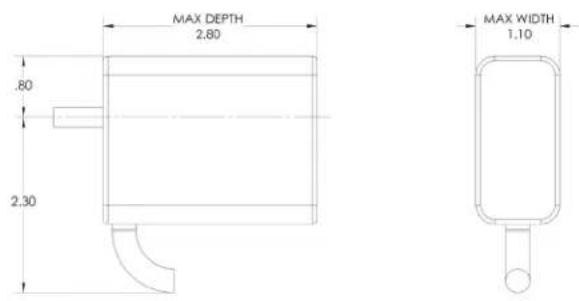
| UWL-10PD | Chromebook | 10 | Padlock | No | 12.5 | 1.48 | 13.9 | 3.1 | 1.1 | 2.8 | 3 | 1.8 | 5.5 |
| UWL-12KD | Chromebook | 12 | Key lock | No | 12.5 | 1.2 | 13.9 | 3.1 | 1.1 | 2.8 | 3 | 1.5 | 5.5 |
| UWL-12PD | Chromebook | 12 | Padlock | No | 12.5 | 1.2 | 13.9 | 3.1 | 1.1 | 2.8 | 3 | 1.5 | 5.5 |
| UWL-10KLD | Chromebook | 10 | Key lock | Yes | 12.5 | 1.48 | 13.9 | 3.1 | 1.1 | 2.8 | 3 | 1.8 | 5.5 |
| UWL-10PLD | Chromebook | 10 | Padlock | Yes | 12.5 | 1.48 | 13.9 | 3.1 | 1.1 | 2.8 | 3 | 1.8 | 5.5 |
| UWL-12KLD | Chromebook | 12 | Key lock | Yes | 12.5 | 1.2 | 13.9 | 3.1 | 1.1 | 2.8 | 3 | 1.5 | 5.5 |
| UWL-12PLD | Chromebook | 12 | Padlock | Yes | 12.5 | 1.2 | 13.9 | 3.1 | 1.1 | 2.8 | 3 | 1.5 | 5.5 |
MAXIMUM WALLMOUNT POWER SUPPLY DIMENSIONS
2.1 INTRODUCTION
The Wallmount Charging Lockers are ideal for smaller classrooms, offices, and training environments that are short on space. The Lockers can be wallmounted or placed on desks, tables, filing cabinets, or shelves. Each Locker is designed to store and charge up to 10 or 12 tablets, 15" Chromebooks, and other similarly-sized devices. You can even create locker walls and blocks by stacking the lockers on top of each other or mounting them side-to-side and back-to-back. Each Locker plugs into a typical 120-V, 15-A outlet.
The Wallmount Charging Lockers can be equipped in eight configurations according to the following standard options/features.
◆ 10 or 12 stored devices
- Adjustable-depth 19" rackmount rails so you can mount IT equipment for different uses
- Locking steel front door
- On some models, a separate keyed lockable drawer provides a place to store electronics
♦ Keyed front door or padlocking front door
The Wallmount Charging Lockers feature a heavy-duty, fully welded steel frame and hold up to 150 pounds.
Please know and understand the configuration of your Locker and read these operating instructions carefully. The manual contains important information concerning the use and safety of your Locker and the operators. This Locker must be used for its intended purpose only and in accordance with these operating instructions.
2.2 WHAT'S INCLUDED
Your package should contain the following items. If anything is missing or damaged, contact Black Box Technical Support at 877-877-2269 or info@blackbox.com.
(1) Locker
(2) sets of keys for front door
◆ (2) sets of keys for locking drawer (if equipped)
CHAPTER 3: CONFIGURATION AND SETUP
NEED HELP? LE AVE THE TECH TO US
LIVE 24/7 TECHNICAL SUPPORT
1.8 7 7.87 7.2269
3.1 UNPACKING
Remove and discard all packaging materials.
Open and inspect the locker to verify all doors and locks are working properly.
Do not plug the locker into a wall outlet until all configurations and setup are complete.
3.2 ROUTING THE CABLES
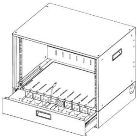
- Open the drawer of the locker and attach the wrapped cord and power brick of the device to the shelf using the hook and loop strap. Keep some extra cable unwrapped to plug into the power strip.
natural_image
Line drawing of a server rack cabinet with internal compartments and mounting holes (no text or symbols)FIGURE 3-1. ROUTING THE CABLES DIAGRAM #1.
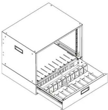
- Place the device power cord into the corresponding cord hanger with the plug going into the device space of the locker.
natural_image
Technical line drawing of an open industrial storage unit with internal compartments and drawers (no text or symbols)FIGURE 3-2. ROUTING THE CABLES DIAGRAM #2.
CHAPTER 3: CONFIGURATION AND SETUP
NEED HELP? LE AVE THE TECH TO US
LIVE 24/7 TECHNICAL SUPPORT
1.8 7 7.87 7.2269
3.3 WALLMOUNTING THE LOCKER ON 16" AND 19" C/C STUDS
Only mount to solid, flush walls with mounting hardware into wood studs only.
- Using the template below, measure and mark out the locations of the desired mounting holes on the wall.
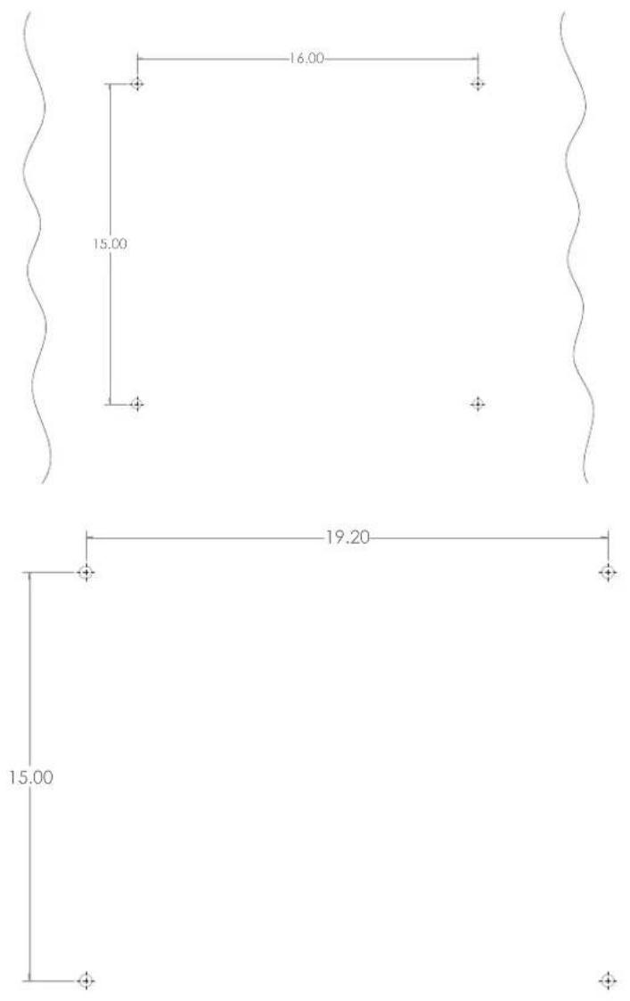
FIGURE 3-3. WALLMOUNTING TEMPLATE
CHAPTER 3: CONFIGURATION AND SETUP
NEED HELP? LE AVE THE TECH TO US
LIVE 24/7 TECHNICAL SUPPORT
1.8 7 7.87 7.2269
- Attach the mounting hardware to the wall as shown below in the corresponding mounting hole locations. Do not screw in completely.
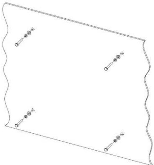
natural_image
Pure geometric diagram with wavy boundary and four marked points (no text or symbols)FIGURE 3-4. ATTACHING THE MOUNTING HARDWARE
- Place the Wallmount Locker onto the mounting hardware on the wall as shown.
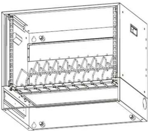
natural_image
Technical line drawing of an open electrical enclosure with internal rack-mounted components (no text or symbols)FIGURE 3-5. PLACING THE LOCKER ON THE MOUNTING HARDWARE
- Tighten the mounting hardware to hold the Wallmount Locker against the wall.
CHAPTER 3: CONFIGURATION AND SETUP
NEED HELP?
LE AVE THE TECH TO US
LIVE 24/7
TECHNICAL
SUPPORT
1.8 7 7.87 7.2269
3.4 PLUGGING IN AND TURNING ON THE LOCKER
After the devices have been loaded into the Locker, plug the power cord of the Locker into a typical wall outlet.
A.1 FCC STATEMENT
This equipment generates, uses, and can radiate radio-frequency energy, and if not installed and used properly, that is, in strict accordance with the manufacturer's instructions, may cause interference to radio communication. It has been tested and found to comply with the limits for a Class A computing device in accordance with the specifications in Subpart B of Part 15 of FCC rules, which are designed to provide reasonable protection against such interference when the equipment is operated in a commercial environment. Operation of this equipment in a residential area is likely to cause interference, in which case the user at his own expense will be required to take whatever measures may be necessary to correct the interference.
Changes or modifications not expressly approved by the party responsible for compliance could void the user's authority to operate the equipment.
This digital apparatus does not exceed the Class A limits for radio noise emission from digital apparatus set out in the Radio Interference Regulation of Industry Canada.
TRADEMARKS USED IN THIS MANUAL
NEED HELP?
LE AVE THE TECH TO US
LIVE 24/7
TECHNICAL
SUPPORT
1.8 7 7.87 7.2269
Black Box ^® and the Double Diamond logo are registered trademarks of BB Technologies, Inc.
UL ^® is a registered trademark of Underwriters' Laboratories.
Any other trademarks mentioned in this manual are acknowledged to be the property of the trademark owners.
NOTES
NEED HELP?
LE AVE THE TECH TO US
LIVE 24/7
TECHNICAL
SUPPORT
1.8 7 7.87 7.2269
NOTES
NEED HELP?
LE AVE THE TECH TO US
LIVE 24/7
TECHNICAL
SUPPORT
1.8 7 7.87 7.2269
NEED HELP?
LEAVE THE TECH TO US
LIVE 24/7
TECHNICAL
SUPPORT
1.87 7.8 7 7.2 269
- TABLE OF CONTENTS
- SAFETY INFORMATION/ELECTRICAL PRECAUTIONS 3
- SPECIFICATIONS......4
- OVERVIEW....6
- CONFIGURATION AND SETUP....7
- APPENDIX A. REGULATORY INFORMATION....11
- TRADEMARKS USED IN THIS MANUAL....13
- SAFETY INFORMATION/ELECTRICAL PRECAUTIONS
- IMPORTANT SAFETY INFORMATION
- ELECTRICAL PRECAUTIONS
- WALLMOUNT CHARGING LOCKERS GENERAL SPECIFICATIONS
- WALLMOUNT CHARGING LOCKERS SPECIFICATIONS BY PART NUMBER
- MAXIMUM WALLMOUNT POWER SUPPLY DIMENSIONS
- INTRODUCTION
- WHAT'S INCLUDED
- CHAPTER 3: CONFIGURATION AND SETUP
- UNPACKING
- ROUTING THE CABLES
- WALLMOUNTING THE LOCKER ON 16" AND 19" C/C STUDS
- PLUGGING IN AND TURNING ON THE LOCKER
- A.1 FCC STATEMENT
- TRADEMARKS USED IN THIS MANUAL
- NOTES
Brand : Black Box
Model : UWL-10PD
Category : Mobile Device Charger