EOM-104-FO - Carte réseau/Adaptateur Moxa - Free user manual and instructions
Find the device manual for free EOM-104-FO Moxa in PDF.


| Product Type | Embedded Network Module |
| Model | EOM-104-FO |
| Brand | Moxa |
| Processor | ARM9 16/32-bit, 166 MHz |
| Memory | On-board 16 MB RAM, 8 MB flash |
| Ethernet Ports | 2 x 10/100BaseT(X) (copper), 2 x 100BaseFX (fiber) |
| Console Port | 1 x RS-232 (TxD, RxD, DTR, DSR, GND) |
| GPIO | 4 programmable I/O pins |
| Watchdog Timer | Built-in |
| Dimensions | 54 x 60 x 8.25 mm (2.13 x 2.36 x 0.32 in) |
| Weight | 21 g |
| Input Voltage | 3.3 VDC |
| Input Current | 1.22 A @ 3.3 V |
| Operating Temperature | -40 to 75°C (-40 to 167°F) |
| Storage Temperature | -40 to 85°C (-40 to 185°F) |
| Humidity | 5 to 95% (non-condensing) |
| Standards | IEEE 802.3, 802.3u, 802.3x, 802.1D, 802.1w, 802.1p |
| EMI Certifications | FCC Part 15 Subpart B Class A, EN 55022 Class A, CE Class A |
| Warranty | 5 years |
| Evaluation Kit Available | Yes (EOM-104-DK carrier board included) |
Frequently Asked Questions - EOM-104-FO Moxa
User questions about EOM-104-FO Moxa
0 question about this device. Answer the ones you know or ask your own.
Ask a new question about this device
Download the instructions for your Carte réseau/Adaptateur in PDF format for free! Find your manual EOM-104-FO - Moxa and take your electronic device back in hand. On this page are published all the documents necessary for the use of your device. EOM-104-FO by Moxa.
USER MANUAL EOM-104-FO Moxa
EOM-104 Series Hardware User's Manual
Second Edition, April 2012
www.moxa.com/product
MOXA®
© 2012 Moxa Inc. All rights reserved.
EOM-104 Series
Hardware User's Manual
The software described in this manual is furnished under a license agreement and may be used only in accordance with the terms of that agreement.
Copyright Notice
© 2012 Moxa Inc., All rights reserved.
Trademarks
The MOXA logo is a registered trademark of Moxa Inc.
All other trademarks or registered marks in this manual belong to their respective manufacturers.
Disclaimer
Information in this document is subject to change without notice and does not represent a commitment on the part of Moxa.
Moxa provides this document as is, without warranty of any kind, either expressed or implied, including, but not limited to, its particular purpose. Moxa reserves the right to make improvements and/or changes to this manual, or to the products and/or the programs described in this manual, at any time.
Information provided in this manual is intended to be accurate and reliable. However, Moxa assumes no responsibility for its use, or for any infringements on the rights of third parties that may result from its use.
This product might include unintentional technical or typographical errors. Changes are periodically made to the information herein to correct such errors, and these changes are incorporated into new editions of the publication.
Technical Support Contact Information
www.moxa.com/support
Moxa Americas
Toll-free: 1-888-669-2872
Tel: +1-714-528-6777
Fax: +1-714-528-6778
Moxa Europe
Tel: +49-89-3 70 03 99-0
Fax: +49-89-3 70 03 99-99
Moxa China (Shanghai office)
Toll-free: 800-820-5036
Tel: +86-21-5258-9955
Fax: +86-21-5258-5505
Moxa Asia-Pacific
Product Features 1-2
EOM-104 Hardware Specifications....1-3
EOM-104 Hardware Block Diagram 1-4
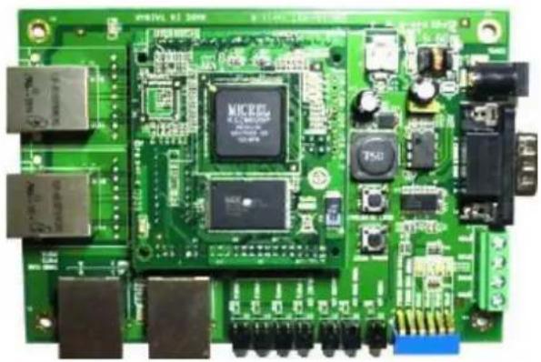
Appearance—EOM-104 Evaluation Kit....1-4
EOM-104 Embedded Module 1-5
EOM-104 Carrier Board 1-5
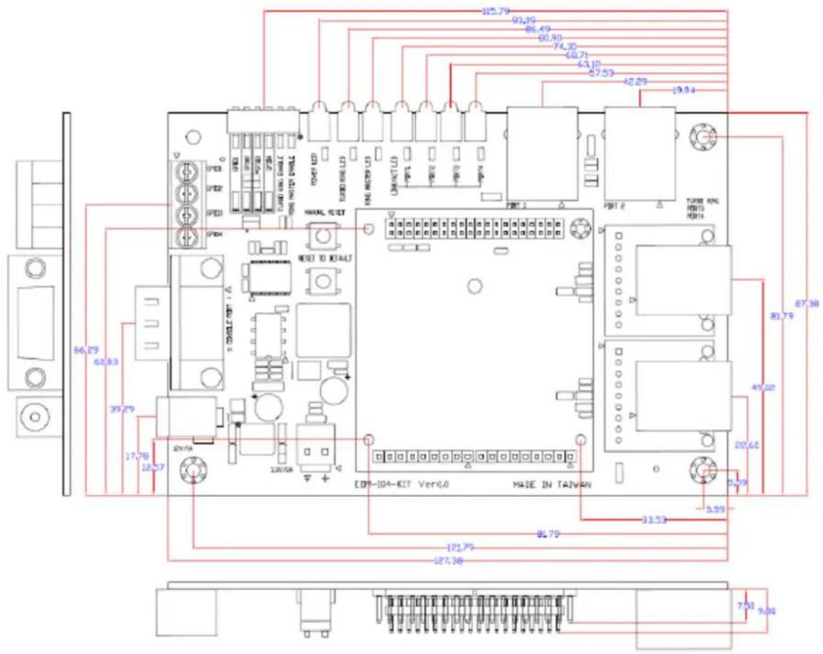
Dimensions (unit: mm) 1-6
2. EOM-104 Functionality 2-1
EOM-104 Embedded Module Functions 2-2
LAN Ports 2-2
Console Port 2-2
GPIO 2-2
Jumper 2-2
Pin Assignments 2-2
Mechanical Specifications of the Pin Headers 2-4
3. EOM-104-DK Functionality 3-1
EOM-104-DK Development Board 3-2
Combining the EOM-104-DK with the Embedded Module....3-2
LED Indicators....3-2
Wiring Requirements....3-2
Connecting the Power 3-3
External Power Input....3-3
Grounding the EOM-104 Evaluation Kit 3-3
Console Ports and Pin Assignments 3-3
LAN Ports and Pin Assignments 3-4
Reset Button 3-4
Dip Switch and Terminal Block 3-4
Schematic 3-5
4. PCB and Layout Guideline 4-1
General Rules....4-2
Power Ground Rules....4-2
Chassis Ground 4-2
Magnetic Noise Zone 4-2
Differential Signal Layout....4-3
ESD Protection 4-3
Thank you for purchasing the Moxa EOM-104 Embedded Module. The product's features include four 10/100 Mbps Ethernet ports, one UART serial ports. These features make the EOM-104 ideal for the core module of an industrial embedded system design.
The EOM-104 Evaluation Kit, which is designed for system and software program development at the system evaluation stage, is also available. The kit includes the EOM-104 and EOM-104-DK, which is the carrier board used to evaluate the EOM-104.
In this manual, we introduce the hardware features and functions of the EOM-104 Embedded Module and the EOM-104 Evaluation Kit. After a brief introduction to the hardware features, the manual focuses on installation and hardware configuration with device interfaces.
The following topics are covered in this chapter:
Overview
□ Package Checklist
□ Product Features
☐ EOM-104 Hardware Specifications
☐ EOM-104 Hardware Block Diagram
☐ Appearance—EOM-104 Evaluation Kit
EOM-104 Embedded Module
EOM-104 Carrier Board
➢ Dimensions (unit: mm)
Overview
The EOM-104 Embedded Module is designed for system integration in industrial Ethernet applications. The module features one UART serial ports, four 10/100 Mbps Ethernet ports. In addition, you may order the EOM-104 Evaluation Kit. The kit includes an EOM-104 embedded module, an EOM-104-DK carrier board, and the items needed for setting up. The kit is makes it easy for users to evaluate the functionality of the EOM-104. You can develop and integrate specific systems on the module in advance to make the EOM-104 Embedded Module completely compatible with industrial systems and applications. The EOM-104 lets you build an application with a powerful Ethernet switch capability, while small in size. The EOM-104 is suited for control systems that use a distributed, embedded architecture, such as those systems used for manufacturing automation, intelligent transportation systems, medical management, and data acquisition and control.
Package Checklist
The EOM-104 package includes the EOM-104 Eembedded Mmodule only. The EOM-104 Evaluation Kit is available for evaluation purposes. The EOM-104 Evaluation Kit package contains the following items:
• One EOM-104 Embedded Module
• One EOM-104-DK, the carrier board of the EOM-104 Evaluation Kit
- Quick Installation Guide
• Document & Software CD
- Ethernet cable
- Null modem cable
• Universal Power Adaptor
- Warranty Statement
NOTE Please notify your sales representative if any of the above items are missing or damaged.
Product Features
The EOM-104 Embedded Module has the following features:
• ARM9 16/32-bit 166 MHz processor
• On-board 16 MB RAM, 8 MB flash
• Four 10/100 Mbps Ethernet for network switching
• One UART serial ports for console control
• Built-in Watchdog Timer
• Four GPIOs reserved for system integration
- Compact size design for easy integration at any field site
• Full-function Evaluation Kit for quick evaluation and application development
- -40 to 75 o C wide temperature
EOM-104 Hardware Specifications
Technology
Standards:
IEEE 802.3 for 10BaseT
IEEE 802.3u for 100BaseT(X) and 100BaseFX
IEEE 802.3x for flow control
IEEE 802.1D for Spanning Tree Protocol
IEEE 802.1w for Rapid STP
IEEE 802.1p for Class of service
Protocols: SNMPv1/v2c/v3, DHCP Client, BootP, TFTP, SMTP, RARP, RMON, HTTP, Telnet, Syslog
MIB: MIB-II, Ethernet-Like MIB, P-Bridge MIB, Bridge MIB, RSTP MIB, RMON MIB Group 1, 2, 3, 9
Flow Control: IEEE 802.3x flow control
Switch Properties
MAC Table Size: 1 K
Packet Buffer Size: 512 Kbit
Interface
Ethernet Ports:
EOM-104: 4 10/100BaseT(X) ports
EOM-104-FO: 2 10/100BaseT(X) and 2 100BaseFX ports
Connectors: 1 connector with 2 x 20 pins, 2 connectors with 1 x 9 pins, and 1 connector with 2 x 2 pins
Console Port: RS-232 (TxD, RxD, DTR, DSR)
GPIO: 4 programmable I/O pins
Power Requirements
Input Voltage: 3.3 V
Input Current:
EOM-104: 0.59 A @ 3.3 V
EOM-104-FO: 1.22 A @ 3.3 V
Physical Characteristics
Dimensions: 54 x 60 x 8.25 mm (2.13 x 2.36 x 0.32 in)
Weight: 21 g
Environmental Limits
Operating Temperature: -40 to 75°C (-40 to 167°F)
Storage Temperature: -40 to 85°C (-40 to 185°F)
Ambient Relative Humidity: 5 to 95% (non-condensing)
Standards and Certifications
EMI: FCC Part 15 Subpart B Class A, EN 55022 Class A, CE Class A
Note: Please check Moxa's website for the most up-to-date certification status.
Warranty
Warranty Period: 5 years
Details: See www.moxa.com/warranty
EOM-104 Hardware Block Diagram
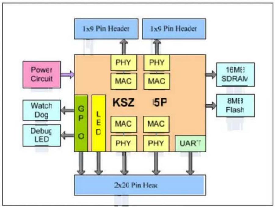
flowchart
graph TD
    A["1x9 Pin Header"] --> B["PSY"]
    C["1x9 Pin Header"] --> D["PHY"]
    B --> E["MAC"]
    D --> F["MAC"]
    E --> G["16ME3 SDRAM"]
    F --> H["8ME3 Flash"]
    I["Power Circuit"] --> J["GPO"]
    K["Watch Dog"] --> L["LED"]
    M["Debug LED"] --> N["GPIO"]
    O["2x20 Pin Head"] --> P["UART"]
    Q["KSZ 5P"] --> R["PHY"]
    Q --> S["MAC"]
    Q --> T["PHY"]
    Q --> U["MAC"]
    Q --> V["UART"]
Appearance—EOM-104 Evaluation Kit
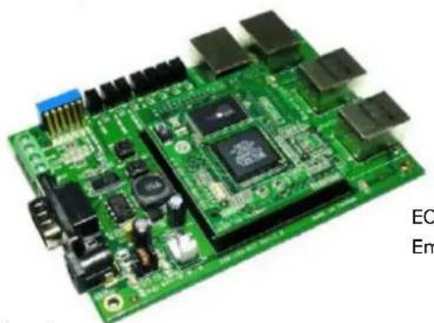
natural_image
Green printed circuit board with various electronic components and connectors (no visible text or symbols)EOM-104 Module
Embedded Module
EOM-104 Carrier Board
EOM-104 Embedded Module
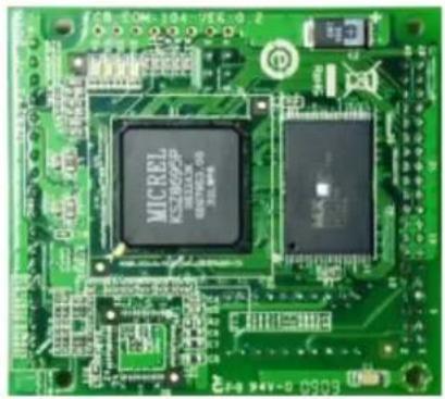
natural_image
Close-up of a green printed circuit board with two black integrated circuits (MICREL and one unlabeled) and no visible text or symbols.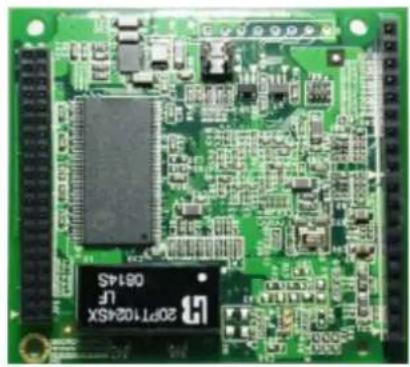
natural_image
Green printed circuit board with integrated circuits and components (no readable text or symbols)EOM-104 Carrier Board
natural_image
Green printed circuit board with various electronic components and connectors (no readable text or symbols)Dimensions (unit: mm)
In this chapter, we introduce the basic features of the EOM-104 Embedded Module.
The following topics are covered in this chapter:
☐ EOM-104 Embedded Module Functions
LAN Ports
□ Console Port
□ GPIO
□ Jumper
□ Pin Assignments
□ Mechanical Specifications of the Pin Headers
EOM-104 Embedded Module Functions
The EOM-104 Embedded Module is designed to be integrated directly into the user's system and application. The module has four 10/100 Mbps LAN ports, one RS-232 console port, and four GPIO signals. In addition, the EOM-104 uses 32-bit 166 MHz communication processor and non-block switch, which ensures excellent performance for data transmission. The EOM-104 is an ideal solution for manufacturing automation, intelligent transportation monitoring, and remote device control.
LAN Ports
The EOM-104 Embedded Module has four 10/100 Mbps LAN ports that can be used to set up a redundant Ethernet network for non-block operation, and ports 1 and 2 on the module provide an on-board (built-in) transformer with 1.5 KV isolation protection.

ATTENTION
Ports 3 and 4 on the EOM-104 module DO NOT provide an on-board (built-in) transformer. Be sure to include a LAN transformer in your hardware design. For reference, see the EOM-104 Evaluation Kit.
Console Port
The EOM-104 Embedded Module has one RS-232 serial console port for on-site configuration. It supports TxD, RxD, DTR, DSR and GND RS-232 signals. To use the console port for configuration, refer to the Software User's Manual.
GPIO
The EOM-104 Embedded Module provides four software-selectable GPIOs. The GPIOs help customers design the functions they need. Refer to the Software User's Manual for details.
Jumper
The EOM-104 Embedded Module provides "JP3" for configuring the Turbo Ring function. Turbo Ring is supported on ports 3 and 4 on the module. (Ports 1 and 2 are not supported.). JP3 is a 2 x 2 pin connector (4 pins), Short pin 3 with pin 4 to enable Turbo Ring for ports 3 and 4. Similarly, short pin 1 with pin 2 to enable ports 3 and 4 to be the "Ring Master" of the Turbo Ring network.
JP3 Jumper
| Functions Pin Number | ||
| RING MASTER ENABLE 1 2 | ||
| TURBO RING ENABLE 3 4 | ||
Pin Assignments
There are one 40-pin pin headers and two 9-pin pin headers on the EOM-104 embedded module. To use the EOM-104 Embedded Module to develop your own independent system, refer to the following tables for the pin assignments.
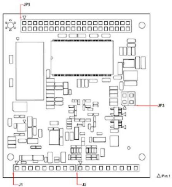
Mechanical Specifications of the Pin Headers
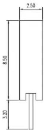
Refer to the following figures for the mechanical specifications of the Pin Headers on the EOM-104 Embedded Module. The figure1 define the mechanical specifications of JP1. The figure2 define the mechanical specifications of J1 and J2.
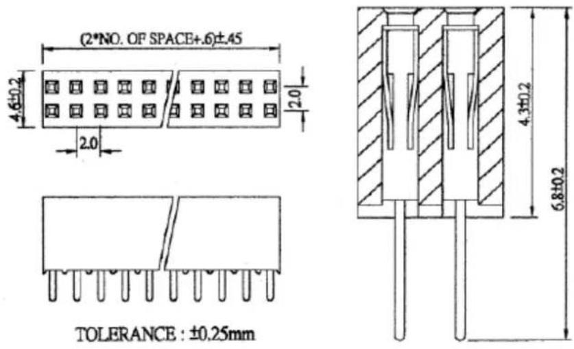

natural_image
Pure geometric pattern of six identical squares arranged horizontally within a rectangular border (no text or symbols)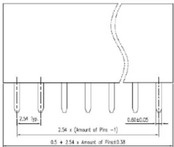
This chapter includes information about the EOM-104-DK (carrier board of the EOM-104 Evaluation Kit).
The following topics are covered in this chapter:
☐ EOM-104-DK Development Board
☐ Combining the EOM-104-DK with the Embedded Module
□ LED Indicators
□ Wiring Requirements
□ Connecting the Power
External Power Input
☐ Grounding the EOM-104 Evaluation Kit
□ Console Ports and Pin Assignments
☐ LAN Ports and Pin Assignments
□ Reset Button
□ Dip Switch and Terminal Block
□ Schematic
EOM-104-DK Development Board
The EOM-104 Evaluation Kit is a well-designed PCB board with complete layout. The kit helps users evaluate, develop, and integrate the EOM-104 Embedded Module into their systems and applications. Simply combine the EOM-104 Embedded Module with the Evaluation Kit to start porting the relevant software, and create a solution for the applications you wish to implement.
Combining the EOM-104-DK with the Embedded Module
Insert the EOM-104 Embedded Module vertically onto the EOM-104-DK. Note that the Pin marked "JP1" on the Embedded Module must be matched with the Pin marked "JP5" on the EOM-104-DK. Be careful when installing the board to avoid damaging the pins.
LED Indicators
The following table explains the function of the LED indicators located on the EOM-104-DK.
| LED Name | LED Color | LED Function |
| Power | Yellow | Power is on and system functions normally. |
| TURBO RING | Green | Lights up when the Turbo Ring function is enabled |
| RING MASTER | Green | Lights up when device is set to Ring Master. |
| GPIO 1 to 4 | Green | Lights up when GPIO output is 1. |
| Port 1 to 4 | Green | Ethernet port status is “Link” |
| Port 1 to 4 | Flash | Ethernet port is transferring data. |
Wiring Requirements
This section describes how to connect the EOM-104 Evaluation Kit to devices.
Please read the following safety precautions before proceeding with the installation of any electronic device:
- Use separate paths to route wiring for power and devices. If power wiring and device wiring paths must cross, make sure the wires are perpendicular at the intersection point.
NOTE: Do not run signal or communication wiring and power wiring in the same wire conduit. To avoid interference, wires with different signal characteristics should be routed separately. - Use the type of signal transmitted through a wire to determine which wires should be kept separate. The rule of thumb is that wiring that shares similar electrical characteristics can be bundled together.
- Keep input wiring and output wiring separate.
- It is advisable to label the wiring to all devices in the system.
- Be sure to disconnect the power cord before installing and/or wiring your EOM-104 Evaluation Kit.

ATTENTION
Safety First!
Be sure to disconnect the power cord before installing and/or wiring your EOM-104 Evaluation Kit.
Temperature Caution!
Heat sink might be needed for temperature-sensitive environments if the U2 component on the EOM-104 is hotter then 135^ C.
Connecting the Power
You may use the power jack for connecting the power. The power input range of the EOM-104 Evaluation Kit is from 12 to 24 VDC. If the power is properly supplied, the "Power" LED will light up in yellow after 3 to 5 seconds.
External Power Input
The EOM-104 Evaluation Kit also accepts 3.3 V power input through J5 connector. There is no protection on JP5 to EOM-104. Make sure this external power input is within 3.3 VDC±5% and is capable of providing 1 A of current or higher.
Grounding the EOM-104 Evaluation Kit
Grounding and wire routing help limit the effects of noise caused by electromagnetic interference (EMI).
Connect the ground wire from the ground screw to the grounding surface before connecting devices.

ATTENTION
This product should be mounted to a well-grounded mounting surface such as a metal panel.
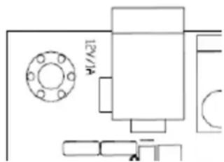
FG: The Functional Ground contact is the PTH(Plated Through Hole) screw hole at left of J4 as shown in left figure. Be sure to connect the FG wire to an appropriate grounded metal surface.
Console Ports and Pin Assignments
The serial console port on the EOM-104 Evaluation Kit is a DB9 type RS-232 DTE port, which supports TxD, RxD, DTR, DSR and GND signals. It is designed to configure the EOM-104 embedded module. It can be connected to a PC through a null modem cable.
The pinouts of the RS-232 console port are shown in the figure below.
| Pin | Signal | Pin | Signal |
| 1 NC | 6 DSR | ||
| 2 RxD | 7 NC | ||
| 3 TxD | 8 NC | ||
| 4 DTR | 9 NC | ||
| 5 GND | - | - |
LAN Ports and Pin Assignments
The EOM-104 Evaluation Kit has four 10/100 Mbps LAN ports for connecting to network.
The LAN ports use 8-pin RJ45 connectors. See the following diagram for the pinouts.
 | Pin | Signal |
| 1 | Tx+ | |
| 2 Tx- | ||
| 3 Rx+ | ||
| 4 - | ||
| 5 - | ||
| 6 Rx- | ||
| 7 - | ||
| 8 - |
Reset Button
The EOM-104 Evaluation Kit has two reset buttons, "Manual Reset" and "Reset to Default."
Press the Manual Reset button for hardware reset of the EOM-104 Evaluation Kit and the EOM-104 embedded module.
Press the Reset button continuously for at least 5 seconds to load the software factory default configuration.
After the factory default configuration has been loaded, the system will reboot automatically.
Dip Switch and Terminal Block
The EOM-104 Evaluation Kit provides one 6-pin dip switch and one 4-pin terminal block. Each pin on terminal block can be input or output depending on the user's definition.
Function Table:
| Function | Dip Pin | Terminal Block | LED |
| Ring Master Enable S1-1 | |||
| Turbo Ring Enable S1-2 | |||
| GPIO4 | S1-3 | J3-4 | D13 |
| GPIO3 | S1-4 | J3-3 | D12 |
| GPIO2 | S1-5 | J3-2 | D11 |
| GPIO1 | S1-6 | J3-1 | D10 |
Schematic
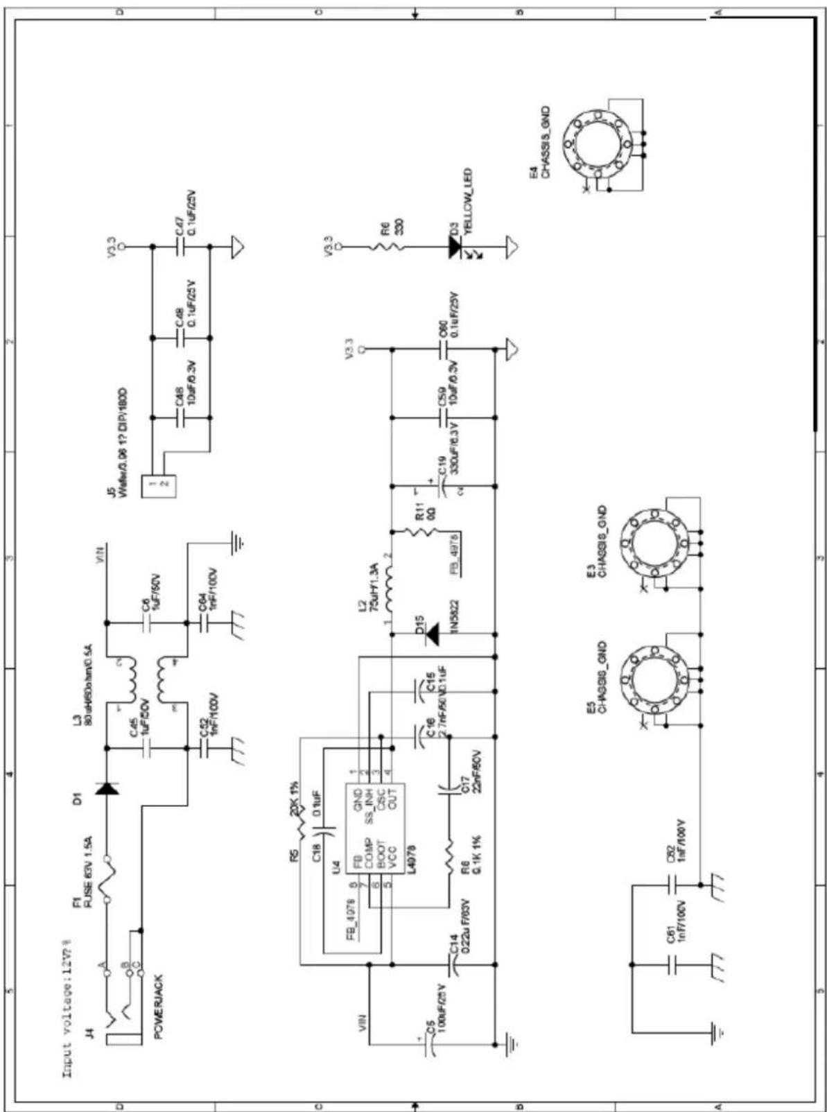
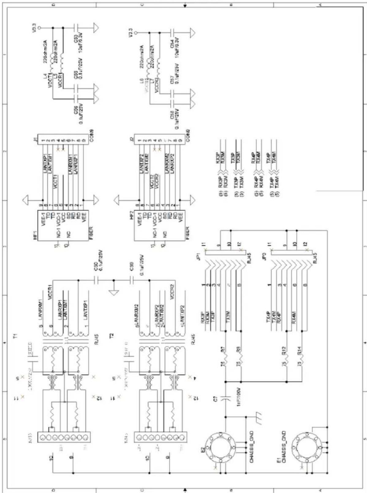
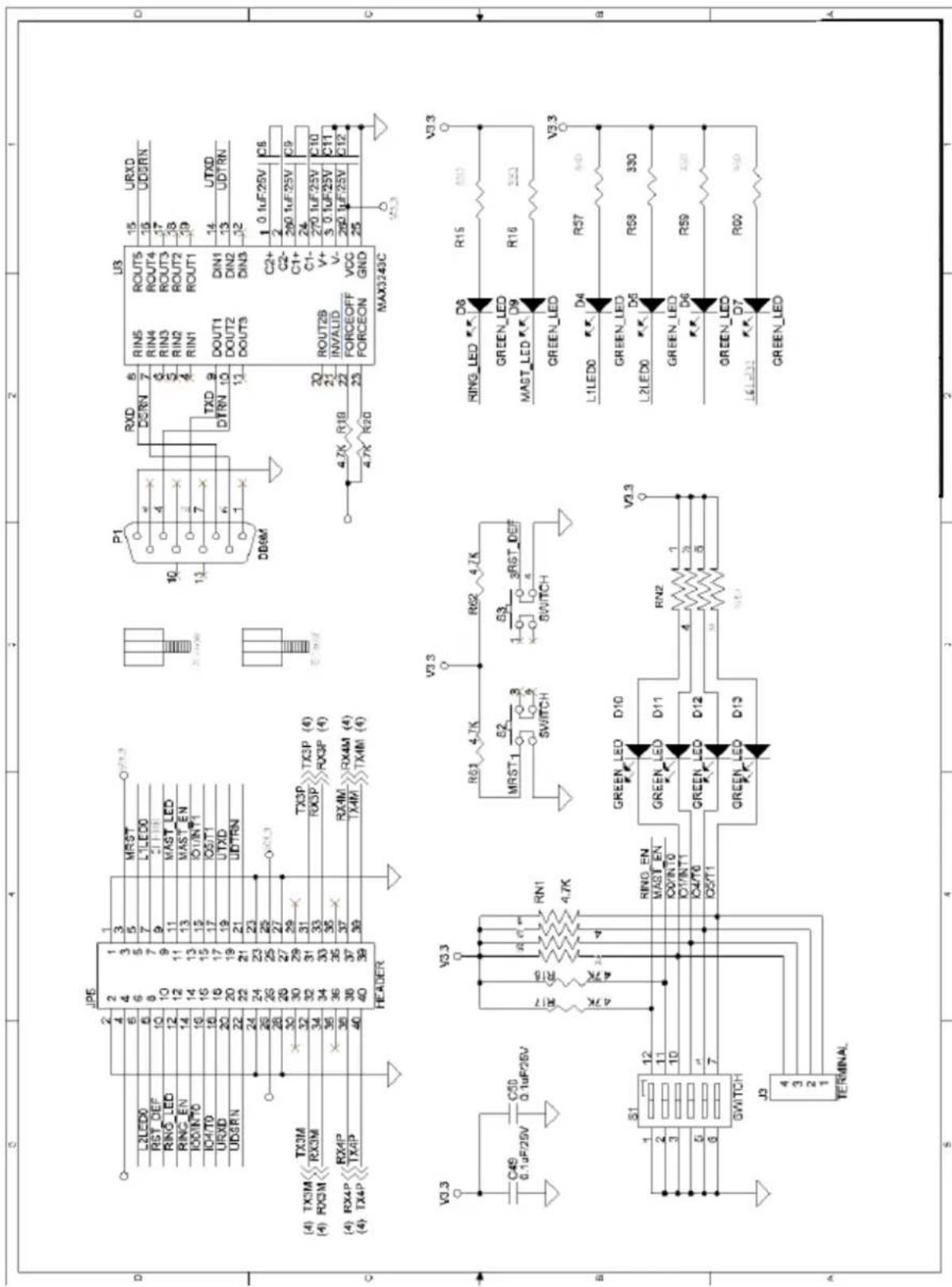
This chapter describes how to design your product with the EOM-104 embedded module to complying with EMI and EDS standards.
The printed circuit board is the most important factor that affects EMI, ESD and the performance. The design skills in this chapter are to minimize digital and common mode noises and provide shielding between the PCB's internal circuit and the external environment. These PCB design skills should apply to the entire PCB design.
The following topics are covered in this chapter:
General Rules
Power Ground Rules
□ Chassis Ground
□ Magnetic Noise Zone
☐ Differential Signal Layout
□ ESD Protection
General Rules
Place components so as to avoid long loop traces. Choose a metal box to shield the printed circuit board.
Use a ferrite core on the DC power cord to reduce EMI. PCB and Layout Guideline Provide controlled impedance on all high-speed digital signals traces with right termination schemes to prevent reflection and ringing. Ensure that the power line is rated for the application and optimized with decoupling capacitors. Keep power and ground noise under 100mV peak to peak. Ensure that the switching DC-DC converter is filtered and properly shielded as the DC-DC power converter can produce a great deal of EMI noise. Avoid via and pad in the path on any critical signal as via and pad will induce unwanted capacitance and inductance which can cause reflection and distortion.
Power Ground Rules
Do not split the ground plane into separate planes for analog, digital, power pins. A single and contiguous ground plane is recommended. Route high-speed signals above a solid and unbroken ground plane. Fill copper in the unused area of signal planes and connect these coppers to the ground plane through vias. Stagger the placement of vias to avoid creating long gap in the plane due to via voids.
Chassis Ground
The chassis ground and magnetics serve two purposes: they help to reduce EMI noise emissions from the signal ground plane to the PCB's external environment and also act as a shield to protect the PCB components from ESD. Place the chassis ground on all PCB layers and use connection mounting holes to join the chassis ground on different PCB layers This chassis ground on the PCB is directly connected to the metal shield of equipment through the connection mounting holes. Use a trench/moat to isolate the chassis ground plane from the signal ground plane. The chassis ground region extends from the front edge of the PCB board (RJ45 connectors) to the magnetics and around the edge of the board as shown in below.
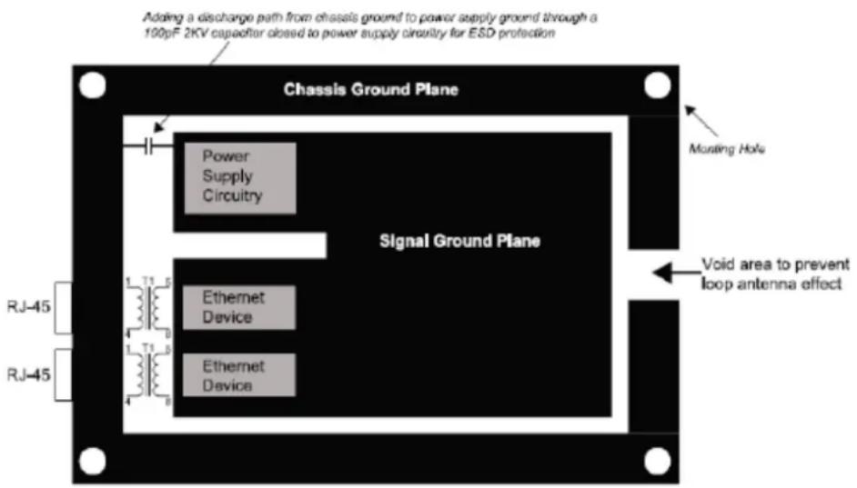
Magnetic Noise Zone
Void both power and ground planes on all PCB layers directly under the magnetics. Chassis ground should extend from the magnetics to the RJ45 connector. Do not route any digital signals between the PHY and RJ45 connector. Add transformer to Port 1 and Port 2 as shown in figure 3 when connecting to external cable is required.
Differential Signal Layout
Differential pair (TX+/- or RX+/-) should be routed away from all other signals and keeps 100 ohms differential Impedance. Keep both traces of each differential pair as identical to each other as possible.
Route each differential pair on the same PCB layer. Route both TX+/- and RX+/- pairs far away from each other at least 20 mil space as shown below.

ESD Protection
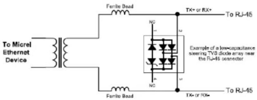
Various ESD protection methods and devices can be used. The level of ESD protection provided by each method varies and depends on the type of protection device used. Consult the specific manufacture's data sheet to determine the level of ESD protection and proper connection. The most essential in ESD protection is to discharge ESD energy to earth and avoid the ESD voltages destroy or cause the circuitry malfunctioning.
Place transient voltage suppressor (TVS) devices and Ferrite bead on the TX +/- and RX+/- differential pairs as figure 4 to help increase ESD protection. These devices are connected in parallel with the I/O lines to be protected.
Connect all unused inputs to either ground with a 1K resistor or power with a 10K resistor, depending on the desired strap-in setting of the chip.
- EOM-104 Series Hardware User's Manual
- EOM-104 Series
- Hardware User's Manual
- Copyright Notice
- Trademarks
- Disclaimer
- Technical Support Contact Information
- Moxa Americas
- Moxa Europe
- Moxa China (Shanghai office)
- Moxa Asia-Pacific
- EOM-104 Functionality 2-1
- EOM-104-DK Functionality 3-1
- PCB and Layout Guideline 4-1
- Overview
- Package Checklist
- Product Features
- EOM-104 Hardware Specifications
- Technology
- Standards:
- Switch Properties
- Interface
- Ethernet Ports:
- Power Requirements
- Input Current:
- Physical Characteristics
- Environmental Limits
- Standards and Certifications
- Warranty
- EOM-104 Embedded Module
- EOM-104 Carrier Board
- EOM-104 Embedded Module Functions
- LAN Ports
- ATTENTION
- Console Port
- GPIO
- Jumper
- Pin Assignments
- Mechanical Specifications of the Pin Headers
- EOM-104-DK Development Board
- Combining the EOM-104-DK with the Embedded Module
- LED Indicators
- Wiring Requirements
- Safety First!
- Temperature Caution!
- Connecting the Power
- External Power Input
- Grounding the EOM-104 Evaluation Kit
- Console Ports and Pin Assignments
- LAN Ports and Pin Assignments
- Reset Button
- Dip Switch and Terminal Block
- Schematic
- General Rules
- Power Ground Rules
- Chassis Ground
- Magnetic Noise Zone
- Differential Signal Layout
- ESD Protection
Brand : Moxa
Model : EOM-104-FO
Category : Carte réseau/Adaptateur