NA-4010 - Network Card/Adapter Moxa - Free user manual and instructions
Find the device manual for free NA-4010 Moxa in PDF.


| Product Type | Network Adapter / Interface Card |
| Model | NA-4010 |
| Manufacturer | Moxa |
| Interface | PCI Express (PCIe) |
| Ports | 2 x Gigabit Ethernet (RJ45) |
| Data Transfer Rate | 10/100/1000 Mbps |
| Dimensions (W x H x D) | 120 mm x 70 mm x 20 mm |
| Weight | Approximately 150 g |
| Power Consumption | Max 5 W (via PCIe bus) |
| Operating Temperature | 0 °C to 60 °C |
| Operating Humidity | 5% to 95% (non-condensing) |
| Supported OS | Windows, Linux, and other major platforms |
| Compliance | CE, FCC |
| LED Indicators | Link/Activity per port |
| Mounting | Low-profile bracket included |
| Warranty | 5 years |
| Maintenance | Keep clean and dry; avoid dust accumulation |
| Safety | Follow standard ESD precautions during installation |
| Spare Parts / Repairability | Contact Moxa support for replacement or repair |
Frequently Asked Questions - NA-4010 Moxa
User questions about NA-4010 Moxa
0 question about this device. Answer the ones you know or ask your own.
Ask a new question about this device
Download the instructions for your Network Card/Adapter in PDF format for free! Find your manual NA-4010 - Moxa and take your electronic device back in hand. On this page are published all the documents necessary for the use of your device. NA-4010 by Moxa.
USER MANUAL NA-4010 Moxa
ioLogik 4000 Series User's Manual
Edition 4.2, April 2020
www.moxa.com/product
MOXA®
© 2020 Moxa Inc. All rights reserved.
ioLogik 4000 Series User's Manual
The software described in this manual is furnished under a license agreement and may be used only in accordance with the terms of that agreement.
Copyright Notice
© 2020 Moxa Inc. All rights reserved.
Trademarks
The MOXA logo is a registered trademark of Moxa Inc.
All other trademarks or registered marks in this manual belong to their respective manufacturers.
Disclaimer
Information in this document is subject to change without notice and does not represent a commitment on the part of Moxa.
Moxa provides this document as is, without warranty of any kind, either expressed or implied, including, but not limited to, its particular purpose. Moxa reserves the right to make improvements and/or changes to this manual, or to the products and/or the programs described in this manual, at any time.
Information provided in this manual is intended to be accurate and reliable. However, Moxa assumes no responsibility for its use, or for any infringements on the rights of third parties that may result from its use.
This product might include unintentional technical or typographical errors. Changes are periodically made to the information herein to correct such errors, and these changes are incorporated into new editions of the publication.
Technical Support Contact Information
www.moxa.com/support
Moxa Americas
Toll-free: 1-888-669-2872
Tel: +1-714-528-6777
Fax: +1-714-528-6778
Moxa Europe
Tel: +49-89-3 70 03 99-0
Fax: +49-89-3 70 03 99-99
Moxa India
Tel: +91-80-4172-9088
Fax: +91-80-4132-1045
Moxa China (Shanghai office)
Toll-free: 800-820-5036
Tel: +86-21-5258-9955
Fax: +86-21-5258-5505
Moxa Asia-Pacific
Product Features 1-2
Product Specifications 1-3
2. Hardware Installation 2-1
System Architecture....2-2
Connecting the Network Adapter to I/O Modules....2-3
Appearance 2-3
Installing I/O Modules on a DIN-Rail 2-4
Removing I/O Modules from a DIN-Rail 2-5
Installing an RTB (Removable Terminal Block) 2-6
Connecting the Power System 2-6
Connecting to the Network....2-7
NA-4010 Ethernet Network Adapter 2-7
NA-4020 RS-485 Network Adapter 2-8
NA-4021 RS-232 Network Adapter 2-8
LED Indicators....2-9
LED Indicators for Network Adapters 2-9
LED Indicators for I/O Modules 2-10
When to Use the Power Expansion Module 2-11
When to Use the Field Power Distributor 2-11
When to Use the Potential Distributor....2-12
Safety Notes 2-12
Installation and Cabling Precautions 2-12
Operating Precautions....2-12
3. Getting Started 3-1
Installing ioAdmin Utility....3-2
Configuring the NA-4010 Ethernet I/O System 3-2
Initializing the IP Address....3-2
Linking the Ethernet I/O System to ioAdmin 3-4
Password Protection 3-6
Reset to Default 3-7
Restart System 3-7
Deleting an I/O Server from the List 3-7
Network 3-8
TCP Socket Timeout Interval....3-9
Watchdog Timer....3-9
Firmware Upgrade 3-10
Exporting the System Configuration....3-10
Remote Monitoring 3-10
I/O Status Refresh Rate 3-10
Checking NA-4010's Ethernet I/O Status via Web Browser 3-11
Entering the Web Console 3-11
Configuring NA-4020/4021's RS-485/RS-232 I/O System 3-12
Setting Communication Parameters 3-12
Linking the RS-485/232 I/O Server to ioAdmin 3-14
Password Protection 3-17
Reset to Default 3-17
Restarting the System 3-18
Deleting an I/O Server from the List 3-18
Watchdog Timer....3-18
Firmware Update....3-18
I/O Status Refresh Rate 3-18
Modbus Address Mapping....3-19
Finding a Modbus Address for I/O Channels 3-19
Exporting Modbus Address Settings 3-19
4. Configuring I/O Modules.... 4-1
Overview 4-2
On-Line Wiring Guide 4-2
Digital Input Module....4-3
Digital Output Module....4-4
Safe Status 4-4
Analog Input Module 4-5
Analog Output Module 4-6
Safe Status 4-6
Temperature Sensing Modules....4-7
RTD 4-7
Thermocouple 4-8
- MXIO DLL Library 5-1
Overview 5-2
MXIO Function Groups....5-2
A. Pinouts and Cable Wiring ...... A-1
Port Pinout Diagrams ......A-2
Ethernet Port Pinouts....A-2
Serial Port Pinouts....A-2
Ethernet Cable Wiring Diagrams ......A-3
The ioLogik 4000 is a standalone Active Ethernet I/O server that can connect sensors and on/off switches for automation applications over Ethernet and IP-based networks.
The following topics are covered in this chapter:
☐ ioLogik 4000 System Overview
□ Package Contents
□ Product Features
□ Product Specifications
ioLogik 4000 System Overview
The ioLogik 4000 is a Network I/O Server that can connect sensors and on/off devices in any combination and can transfer the captured data or device status to a host computer via an Ethernet or RS-485/232 network.
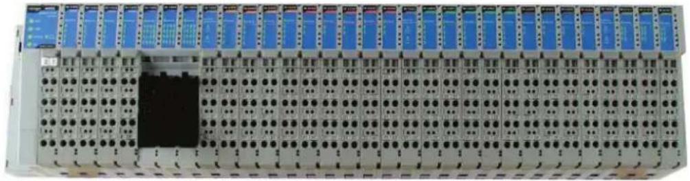
The ioLogik 4000 consists of two main parts. The Network Adapter provides system and field power to connected I/O modules. Three kinds of Network Adapter are available, including Ethernet, RS-485, and RS-232 interfaces. Up to 32 I/O modules can be connected to one Network Adapter.
natural_image
Front view of a multi-chamber industrial control panel with rows of blue and black buttons, no visible text or labelsNetwork
Adapter
I/O expansion modules, up to 32 slots
(Up to 512 DIOs or 128 AIOs)
| Network Adapter | Digital Input | Digital Output | Analog Input | Analog Output | Special Modules | ||||||
| Types | Types | Ch. | Types | Ch. | Types | Ch. | Types | Ch. | Types | Ch. | |
| Ethernet | ~ | 24Vdc | 8,16 | 24Vdc | 8,16 | 4-20mA | 8 | 4-20mA | 4 | Encoder (24V) | 1 |
| RS-485 | ~ | 48Vdc | 4 | 125VAC | 4 | 0-10V | 8 | 0-10V | 4 | ||
| RS-232 | ~ | 110VAC | 4 | 230VAC | 4 | RTD | 2 | ||||
| 230VAC | 4 | TC | 2 | ||||||||
Package Contents
Each Network Adapter and I/O module is packed securely in a small cardboard box.
Network Adapter
• NA-40xx network adapter × 1
I/O Module
• M-xxxx I/O module × 1
Product Features
Detailed specifications of the ioLogik 4000 are available in the software's product specification help files. Refer to the help file for more information.
- Remotely acquire sensor data and control I/O points via Ethernet, RS-232, or RS-485.
• Supports up to 40 types of digital and analog I/O modules. - Expandable up to 32 modules for a maximum of 512 digital I/O points or 128 analog input channels.
- Modular, slice-type package with Removable Terminal Block for fast swap and maintenance.
• Supports standard Modbus/TCP up to 8 concurrent sessions for Ethernet Network Adapters.
• Supports standard Modbus/RTU/ASCII for RS-485/RS-232 Network Adapters. - Easy-to-use ioAdmin utility for remote and local management.
- Easy-to-use DLL library for easy user programming.
Product Specifications
The ioLogik 4000's detailed specifications are available in the software's product specification help files. Refer to the help file for more information. Models supported by this manual are:
| Model Name | Network Adapter |
| NA-4010 | Ethernet Network Adapter Modbus/TCP |
| NA-4020 | RS-485 Network Adapter Modbus/RTU |
| NA-4021 | RS-232 Network Adapter Modbus/RTU |
| Model Name | Digital Input |
| M-1800 | 8 DI, sink, 24 VDC, RTB |
| M-1801 | 8 DI, source, 24 VDC, RTB |
| M-1600 | 16 DI, sink, 24 VDC, RTB |
| M-1601 | 16 DI, source, 24 VDC, 20-pin |
| M-1450 | 4 DI, 110 VAC, RTB |
| M-1451 | 4 DI, 220 VAC, RTB |
| Model Name | Digital Output |
| M-2800 | 8 DO, sink, MOSFET, 24 VDC, 0.5A, RTB |
| M-2801 | 8 DO, source, MOSFET, 24 VDC, 0.5A, RTB |
| M-2600 | 16 DO, sink, MOSFET, 24 VDC, 0.3A, 20 -pin |
| M-2601 | 16 DO, source, MOSFET, 24 VDC, 0.3A, 20-pin |
| M-2450 | 4 DO, Relay, 230VAC, 24 VDC, 2.0A, RTB |
| Model Name | Analog Input |
| M-3802 | 8 AI, Current, 4-20 mA, 12-bit, RTB |
| M-3810 | 8 AI, Voltage, 0-10V, 12-bit, RTB |
| M-6200 | 2 AI, RTD:PT100, JPT100 300 Ohm, RTB |
| M-6201 | 2 AI, Thermocouple:30 mV(1uV/bit), RTB |
| Model Name | Analog Output |
| M-4402 | 4 AO, 4-20 mA, 12-bit, RTB |
| M-4410 | 4 AO, Voltage, 0-10V, 12-bit, RTB |
NOTE The latest specifications for Moxa's products can be found at https://www.moxa.com.
This chapter includes information about installing the ioLogik 4000 I/O Server, including the Ethernet Network Adapter and RS-485, RS-232 Network Adapters. The following topics are covered:
The following topics are covered in this chapter:
□ System Architecture
□ Connecting the Network Adapter to I/O Modules
Appearance
➢ Installing I/O Modules on a DIN-Rail
➢ Removing I/O Modules from a DIN-Rail
➢ Installing an RTB (Removable Terminal Block)
□ Connecting the Power System
□ Connecting to the Network
NA-4010 Ethernet Network Adapter
NA-4020 RS-485 Network Adapter
NA-4021 RS-232 Network Adapter
□ LED Indicators
➢ LED Indicators for Network Adapters
➢ LED Indicators for I/O Modules
☐ When to Use the Power Expansion Module
□ When to Use the Field Power Distributor
☐ When to Use the Potential Distributor
□ Safety Notes
➢ Installation and Cabling Precautions
Operating Precautions
System Architecture
The ioLogik 4000 Slice-type I/O Server consists of a Network Adapter that supports Ethernet, RS-485 or RS-232, and up to 32 I/O modules.
ioLogik 4000's Network Adapter is the brains of the system. Its responsibility is to collect information from each I/O module, and decide the parameters for the I/O module's operation. Communication between the Network Adapter and I/O modules is achieved by a system communication bus.
Modbus Addresses for each I/O channel are arranged dynamically by the Network Adapter, according to the installed I/O modules.
The Network Adapter requires two sets of 24 VDC power inputs. One is for the internal logic circuit, and the other is for field I/O circuits.
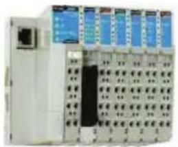
The Network Adapter provides 5 VDC power to all connected I/O modules. When the total current consumption of the I/O modules exceeds 1.5A, you will need to insert an extra power expansion module. To determine how many power expansion modules are required, refer to the spreadsheet in the Start-Program Files-ioLogik-Utility.
natural_image
Industrial control unit with multiple modules and indicator lights (no visible text or labels)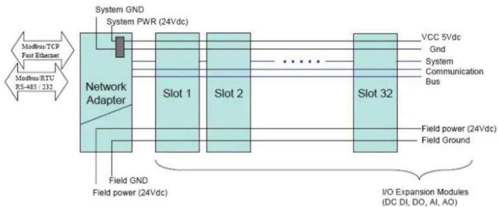
flowchart
graph LR
    A["Modbus/TCP Fast Ethernet"] --> B["Network Adapter"]
    C["Modbus/RTU RS-485 /232"] --> B
    B --> D["Slot 1"]
    B --> E["Slot 2"]
    B --> F["..."]
    B --> G["Slot 32"]
    D --> H["VCC 5Vdc"]
    E --> I["Gnd"]
    E --> J["System Communication Bus"]
    G --> K["Field power (24Vdc)"]
    G --> L["Field Ground"]
    B --> M["Field GND Field power (24Vdc)"]
    M --> N["I/O Expansion Modules (DC DI, DO, AI, AO)"]
Connecting the Network Adapter to I/O Modules
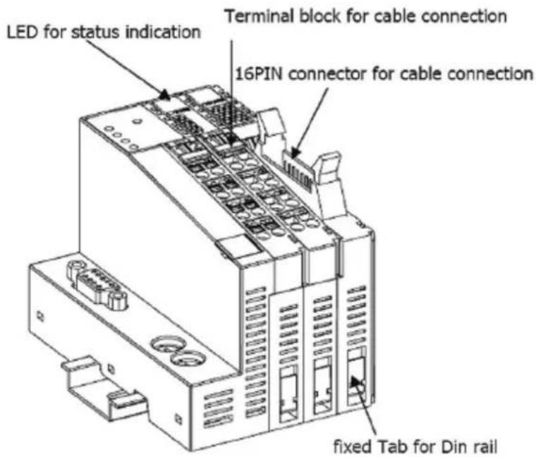
This section describes how to install the ioLogik 4000 I/O modules with the Network Adapter.
Appearance
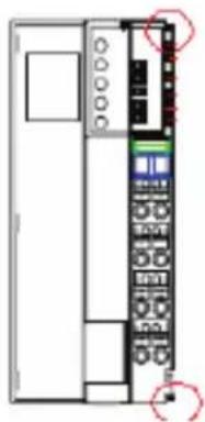
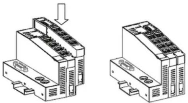
Installing I/O Modules on a DIN-Rail
Step 1: Align the I/O module and Network Adapter side by side, making sure the upper and lower rails are hooked.
natural_image
Front view of a server rack unit with control panel and buttons (no visible text or labels)Step 2: Push the I/O module along the inner rail until it touches the DIN-Rail, and then push hard to clip it onto the DIN-Rail.
natural_image
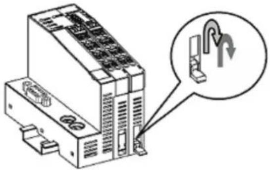
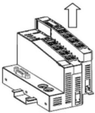
Two technical line drawings of industrial electronic components with no visible text or symbolsRemoving I/O Modules from a DIN-Rail
Step 1: Use your finger or a screw driver to push down the tab located on the lower part of the module.
natural_image
Diagram of an electronic device with labeled ports and a magnified inset showing a curved connector (no text or symbols present)Step 2: Pull out the I/O module.
natural_image
Technical line drawing of an industrial electronic device with a directional arrow indicating upward movement (no text or symbols present)Installing an RTB (Removable Terminal Block)
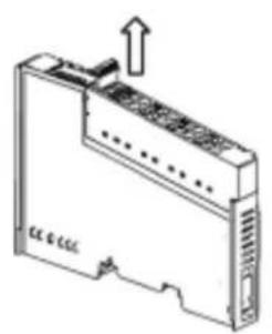
Removing the RTB from the I/O module
Pull hard to remove the plastic belt from the RTB.
natural_image
Diagram of a device rear panel with an arrow indicating upward motion (no text or symbols present)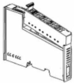
natural_image
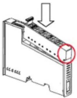
Line drawing of a device with ports and connectors (no text or symbols)Installing the RTB on the I/O module
Align the lower part of the terminal block with the I/O module, and then push the RTB so that it fits into the I/O module.
natural_image
Technical line drawing of a server rack with a highlighted component (no text or symbols)Connecting the Power System
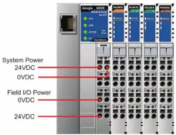
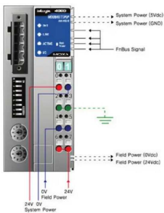
Two 24 VDC power sources are required to activate the ioLogik 4000. One 24 VDC power input is for system power, and the other 24 VDC power input is for field I/O. For field installation, system power and field power are provided by different power supply systems.
Connecting to the Network
NA-4010 Ethernet Network Adapter
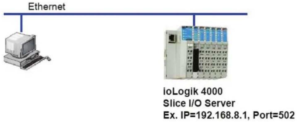
NA-4010 Ethernet Network Adapter supports standard 10/100 Mbps Ethernet. For first time users, we recommend that you link from your host computer to NA-4010 over a local Ethernet network to take care of IP and system configuration. Once the installation is done, you may move the Ethernet I/O system to the field.
Connecting Single Ethernet I/O Server
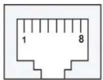
Ethernet pin assignments
| Pin Signal | |
| 1 Tx+ | |
| 2 Tx- | |
| 3 Rx+ | |
| 6 Rx- | |
NA-4020 RS-485 Network Adapter
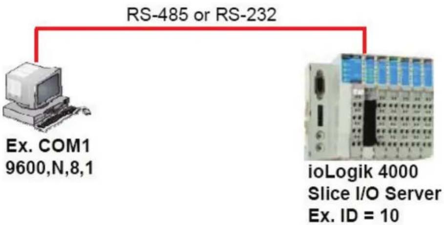
For first time installation, we recommend that you connect the NA-4020 RS-485 Network Adapter to a host computer running the ioAdmin utility to take care of configuration. Once the I/O system is configured, you can move the entire system to the field.
Connecting Single Serial I/O Server
flowchart
graph TD
    A["Ex. COM1\n9600,N,8,1"] --> B["RS-485 or RS-232"]
    B --> C["ioLogik 4000\nSlice I/O Server\nEx. ID = 10"]
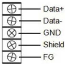
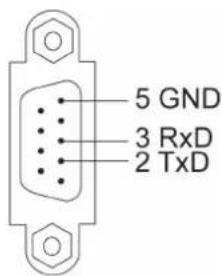
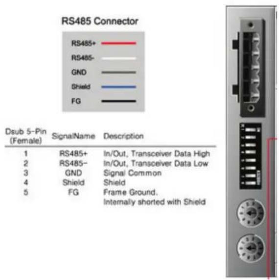
The figure to the right shows the pin assignment of NA-4020's RS-485 port.
NA-4021 RS-232 Network Adapter
For first-time installations, the NA-4021 RS-232 Network Adapter should be connected to a host computer running ioAdmin for system configuration. The figure to the right shows pin assignments for the NA-4021 RS-232 port.
LED Indicators
This section describes the LED indicators on the the ioLogik 4000 system.
LED Indicators for Network Adapters
The NA-4010 Ethernet Network Adapter has 5 LED indicators, as described in the following table.
| LED Name | LED Color | LED Function |
| SYS | Off No power. | |
| Green | Steady On: Operating condition normal. | |
| Red/Green | Toggling: Modbus error (e.g., watch dog timer error) | |
| Red | Steady On: EEPROM checksum error.Flashing: Memory error or CPU watchdog error.* Please contact your vendor for assistance. | |
| LINK | Green | Ethernet connected. |
| ACTIVE | Green | Flashing: Transmitting or Receiving data over Ethernet. |
| I/O | Off No I/O module detected. | |
| Green | Steady On: System bus to I/O modules is running normally.Flashing: System bus to I/O modules ready. But the Network Adapter is not exchanging data with I/O modules. | |
| Red | Steady On: System bus communication failure.Flashing: One or more I/O modules are in an error state.* The following situations may cause a red I/O LED.a. I/O module plugged in during operation.b. I/O module not firmly locked on the rail.c. One of the modules is damaged. | |
| Field Power | Off 24 VDC field power is not connected | |
| Green 24 VDC field power detected | ||
The NA-4020/21 RS-485, RS-232 Network Adapter has 5 LED indicators, as described in the following table.
| LED Name | LED Color | LED Function |
| SYS | Off No power. | |
| Green | Steady On: Operating condition normal. | |
| Red/Green | Toggling: Modbus error (e.g., watch dog timer error) | |
| Red | Steady On: EEPROM checksum error.Flashing: Memory error or CPU watchdog error.* Please contact your vendor for assistance. | |
| RxD | Off No power or communication. | |
| Green | Flashing: Receiving data from the serial port. | |
| TxD | Off No power or communication. | |
| Green Flashing: Sending data to the serial port. | ||
| I/O | Off No I/O module detected. | |
| Green | Steady On: System bus to I/O modules is running normally.Flashing: System bus to I/O modules ready. But the Network Adapter is not exchanging data with I/O modules. | |
| Red | Steady On: System bus communication failure.Flashing: One or more I/O modules are in an error state.* The following situations may cause a red I/O LED.a. I/O module plugged in during operation.b. I/O module not firmly locked on the rail.c. One of the modules is damaged. | |
| Field Power | Off No 24 | VDC field power |
| Green 24 V | DC field power detected | |
LED Indicators for I/O Modules
Each DIO or AIO module is equipped with a Module Status LED indicating operation status.
| LED Name | LED Color | LED Function |
| Status | Off Not powered on during initialization. | |
| Green | Steady On: System ready.Flashing: I/O module ready for communication. | |
| Red | Steady On: I/O module hardware problem.Flashing: System bus communication error. | |
Each DIO or AIO channel is equipped with Channel Status LEDs. Refer to Chapter 4 for more information.
When to Use the Power Expansion Module
When the total current consumption for connected I/O modules exceeds 1.5A, an M-7001 power expansion module is required.
The following table can be used to calculate if an extra power expansion module is needed. In Program Files → ioLogik → Utility, click on Power Consumption Spreadsheet. The spreadsheet requires Microsoft Excel to operate. Once you enter the I/O module quantity, you will know how many power expansion modules are required.
When extra power expansion modules are installed in the ioLogik 4000 I/O Server, restart the system in the following sequence to ensure a proper start-up.
Power Off Sequence
- Unplug the Network Adapter's terminal block.
- Unplug the expansion module's terminal block.
Power Up Sequence
- Plug in the power expansion module's terminal block.
- Plug in the Network Adapter's terminal block.
When to Use the Field Power Distributor
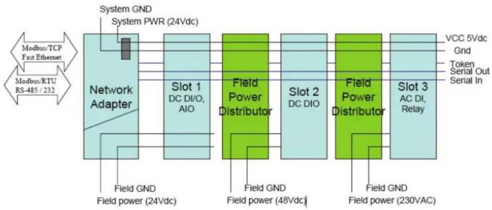
Most of the field power DIO/AIO modules for the ioLogik 4000 series are 24 VDC. If you need to connect 48 VDC or 110 VAC, 230 VAC digital input or output modules, you must use the Field Power Distributor to isolate different field powers within a single ioLogik 4000 system.
If all of the DIO modules are 110 VAC, you will need at least one field power distributor to isolate the field power from the Network Adapter (likewise when using 48 VDC or 230 VAC).
flowchart
graph LR
    A["Modbus/TCP Fast Ethernet"] --> B["Network Adapter"]
    C["Modbus/RTU RS-485 / 232"] --> B
    B --> D["Field Power (24Vdc)"]
    B --> E["Field Power (48Vdc)"]
    B --> F["Field Power (230VAC)"]
    B --> G["Slot 1 DC DI/O, AIO"]
    B --> H["Slot 2 DC DIO"]
    B --> I["Slot 3 AC DI, Relay"]
    D --> J["Field GND Field power (24Vdc)"]
    E --> K["Field GND Field power (48Vdc)"]
    F --> L["Field GND Field power (230VAC)"]
    G --> M["VCC 5Vdc Gnd Token Serial Out Serial In"]
    H --> N["Field Power Distributor"]
    I --> O["Field Power Distributor"]
I/O Expansion Modules (AC-DI, Relay)
When to Use the Potential Distributor
Three types of Potential Distributor module provide extra wiring points, such as shielding ground, field power 0V, and field power 24V.
For example, the 8-channel digital input (sink type) module itself does not have a 24V wiring point. You may add a 24V Potential Distributor for easy wiring.
Safety Notes
Installation and Cabling Precautions
- Check the rated voltage and current for the products before wiring.
- Use the rated power supply and specified cables. Using the wrong power supply could cause a fire.
- Cabling should be done by a certified electrician according to the Electricity Engineering Regulations.
- Improper cabling could cause a fire, or electric shock.
Operating Precautions
- Do not touch the terminal when the power is on to avoid electric shock.
- Do not assemble the product when the power is on.
- Do not modify the wiring while operating the product.
- Pay attention to the power linkage procedure. An incorrect process flow could lead to mechanical damage or other hazards.

ATTENTION
The End Module should be covered in to prevent unexpected damage from exposure of the data pin.
This chapter introduces the method you should follow when configuring the ioLogik 4000 Ethernet I/O system and ioLogik 4000 RS-485/232 I/O system.
The following topics are covered in this chapter:
□ Installing ioAdmin Utility
☐ Configuring the NA-4010 Ethernet I/O System
▶ Initializing the IP Address
- Linking the Ethernet I/O System to ioAdmin
➢ Password Protection
Reset to Default
Restart System
➢ Deleting an I/O Server from the List
Network
TCP Socket Timeout Interval
Watchdog Timer
Firmware Upgrade
- Exporting the System Configuration
Remote Monitoring
▶ I/O Status Refresh Rate
□ Checking NA-4010's Ethernet I/O Status via Web Browser
- Entering the Web Console
☐ Configuring NA-4020/4021's RS-485/RS-232 I/O System
Setting Communication Parameters
- Linking the RS-485/232 I/O Server to ioAdmin
➢ Password Protection
Reset to Default
▶ Restarting the System
➢ Deleting an I/O Server from the List
▶ Watchdog Timer
Firmware Update
I/O Status Refresh Rate
Modbus Address Mapping
➢ Finding a Modbus Address for I/O Channels
- Exporting Modbus Address Settings
Installing ioAdmin Utility
ioAdmin can be downloaded from Moxa's website.
1. Installing ioAdmin from website:
a. First click on the following link to access the website's search utility: http://www.moxa.com/support/search.aspx?type=soft
b. When the web page opens, enter the model name of your product in the search box.
c. Click the model name and navigate to the product page, and then click on Utilities, located in the box titled Software.
d. Download and then unzip the file. Run SETUP.EXE from that location.
The installation program will guide you through the installation process and install the software.
- Open ioAdmin: After installation is finished, run ioAdmin from the Windows Start menu: Start → Program Files → MOXA → IO Server → Utility → ioAdmin.

Configuring the NA-4010 Ethernet I/O System
Initializing the IP Address
- Check the MAC Address, which is located on the label on the left side of the Network Adapter. You may use it to reconfigure the IP address at a later time.
- Determine whether your ioLogik 4000 needs to use a Static IP or Dynamic IP (BOOTP application).
- If the ioLogik 4000 is used in a Static IP environment, you can use ioAdmin to configure the new IP address. The factory default IP address is 192.168.127.254.
- If the ioLogik 4000 is used in a Dynamic IP environment, you can use ioAdmin to make sure BOOTP is enabled. The factory default for BOOTP is "enabled."

ATTENTION
Consult your network administrator if you do not know how to reserve a fixed IP address for your ioLogik 4000 in the MAC-IP mapping table when using a BOOTP Server. In most applications, you should assign a fixed IP address to your ioLogik 4000.
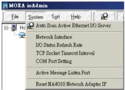
- To set a new IP address for an Ethernet I/O server, run ioAdmin, and then click on Reset NA 4010 Network Adapter IP.
Enter the MAC Address of the NA-4010, and the new IP address. To complete the configuration, click on Reset.
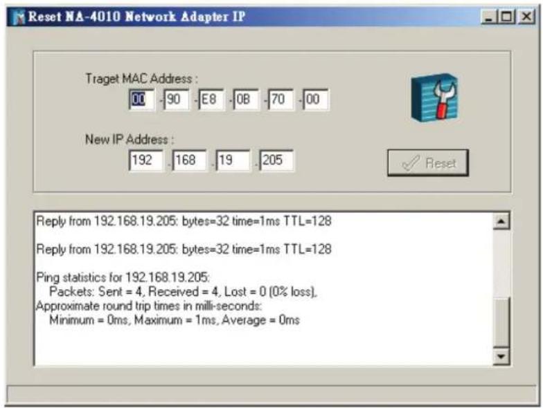
ioAdmin automatically changes the IP address and tests the new IP.
-
In case you do not have ioAdmin installed on your host computer, you may use the ARP command manually to set a new IP address for the NA-4010.
-
Note that this approach only applies when the host computer and the Ethernet Network Adapter are on the same subnet. For first time users, the default IP is 192.168.127.254.
For first time installation, type the following commands at the Windows DOS prompt.
* The MAC address is printed on the left side of the Ethernet network adapter.
>ping 192.168.123.236 //current IP address
>arp -a //view Ethernet physical address
>arp -d 192.168.123.236 //delete arp table
>arp -s 192.168.123.237 10-00-00-10-00-00 //assign static arp table with new IP address
>ping -n 1 l 741 192.168.123.237 //assign new IP address
>arp -d * //clear all arp table
>ping 192.168.123.237 //check response of adapter new IP address
After the IP-Address is set up using ARP:
IP Address = 192.168.123.237
Subnet Mask = 255.255.255.0
Gateway = 192.168.123.254
Linking the Ethernet I/O System to ioAdmin
Before using ioAdmin to link to the Ethernet I/O system, make sure the Ethernet connection for both the I/O server and host computer are working normally. You should also make sure that the power to the I/O server is on.
There are two ways to use ioAdmin to link to the Ethernet I/O server: (1) Auto Search, (2) Manually enter the IP address.
To start the Auto Search function, click on Auto Scan Module(s) under System.
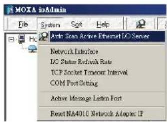
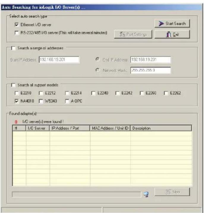
Select Ethernet adapter, and then click on Start Search. ioAdmin will start searching for installed NA-4010's on the network.
The Auto Search function can only find Ethernet I/O Servers that are on the same subnet. To connect to Ethernet I/O Servers outside the subnet, you will need to add the Ethernet I/O server manually.
To input the Network Adapter's IP address manually, press the right mouse key, and then click on ioLogik in the left ioAdmin frame.
![MOXA ioAdmin File System Sort Help Host : [192.168.19.201] ioLogik Add ioLogik I/O Server](/content/2026/05/997942/images/8304f33a231f910e69fb0929c4b3ea32e839aed1ce4520e1eca242f41493bc9f.jpg)
Click on NA-4010, and then enter the IP address.
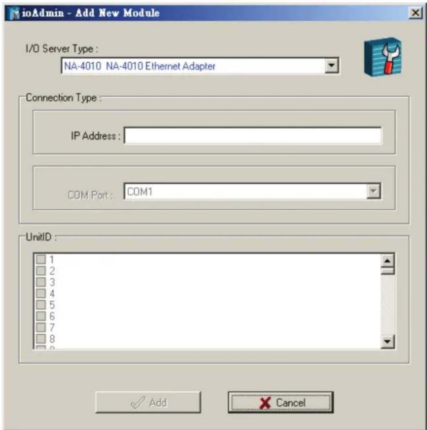
After using auto search, or keying in the ioAdmin IP address manually, the Ethernet I/O servers that were located will appear as follows.
![MOKA v0Admin v1.00 File System Sort Help Host: [192.168.811] v1.log 192.168.127.254 NA-4010 01: M-1800 02: M-2404 03: M-2403 04: M-3412 05: M-3403 06: M-4211 07: M-4202 08: M-6201 09: M-6200 NA-4010. Ethernet (Modbus/TCP) on-line System | Adapter Info. | Management | Slice Description M-1800 M-1800.8D1.sink.24VDC.RTB M-2404 M-2404.4DD.sink.MOSFET.dog..24VDC.2.0A.RTB M-2403 M-2403.4DD.source.MOSFET.dog..24VDC.0.5A.RTB M-3412 M-3412.4AI.Voltage.-10~10V.12bit.RTB](/content/2026/05/997942/images/61a07dc47c8d659557b7cf4b0fb17f0f77703344b56c68f8a7b83c4545fe2125.jpg)
The left frame of ioAdmin shows the I/O Servers connected to the network that were located by the search process. The upper right frame indicates the combination of all I/O modules by slot number. The lower right frame lists detailed information for installed I/O modules.
If you move the mouse cursor over any of the I/O modules, the model name and description will be displayed automatically.
At this point, your Ethernet I/O system should be up and running. The next section explains additional ioLogik 4000 management issues. You may also jump to Chapter 4 and check the status for each I/O channel.
Password Protection
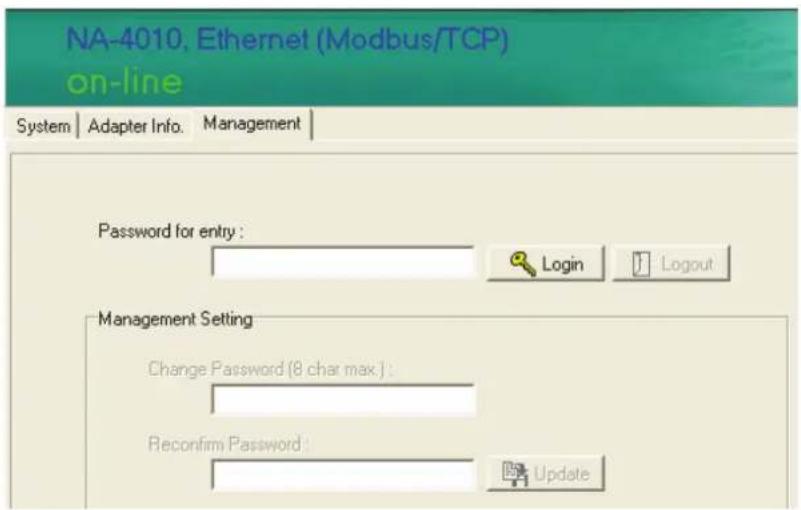
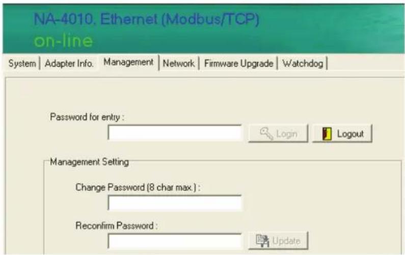
Network configuration, Firmware Upgrade, Watchdog configuration, Reset to Default, and Restart System can all be protected by a password to prevent unauthorized access.
The password is blank by default. If there you have not set a password, you may click on Login to show the tabs for firmware upgrade, network configuration, and watchdog configuration.
Reset to Default
The Network Adapter settings, including IP address, netmask, gateway, watchdog timer, I/O module safety status, and temperature sensor parameters are stored in the network adapter.
Right click on the target I/O server, and then click on Reset to Default to proceed. You may need to wait 10 seconds or longer. ioAdmin will reconnect the I/O Server automatically.
Note that this function requires password authorization to activate.
Default values for NA-4010 Ethernet Network Adapter are as follows.
Bootp: on
ARP: on
IP: 192.168.127.254
Network mask: 255.255.0.0
Gateway: (Empty)
Modbus watchdog: disable
Watchdog timeout: 60 sec (120 x 0.5sec)
Password: Empty
Restart System
In general, you do not need to restart the I/O server when changing I/O module configurations. However, when the I/O Server indicates an I/O error, you may use this function to restart the I/O Server system remotely.
Right click on the target I/O server, and then click on Restart System to proceed. You may need to wait 10 seconds or longer. ioAdmin will reconnect the I/O Server automatically.
Note that this function requires password authorization to activate.
Deleting an I/O Server from the List
When several I/O Servers appear in ioAdmin's left frame, you can delete I/O Servers from the list to make your management task easier.
Right click on the target I/O Server and then press Disconnect. Right click on the target I/O Server and then press Delete I/O Server. The target I/O Server will be removed from the list.
Note that this function requires disconnected from the ioLogik to activate.
![MOXA ioAdmin File System Sort Help Host : [192.168.19.201] ioLogik 192.168.19.206 NA-4010 Connect Disconnect Delete I/O Server Restart System Reset to Default Export System Config](/content/2026/05/997942/images/b13a388f8c89862f06c565ca1811fcc11b3faf244dd74191c821e4aa0cdbf9f0.jpg)
Network
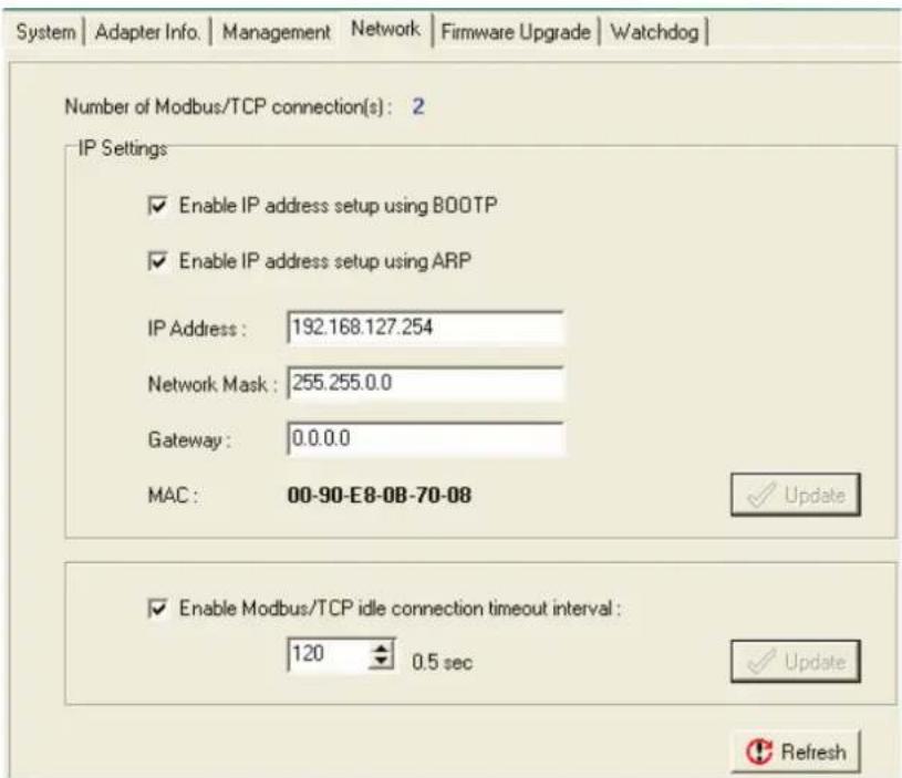
Click on the Network Adapter's Network tab to change the IP Address, Network Mask, Gateway, and MAC address. There are two options for IP configuration: Bootp and ARP. We strongly recommend that you leave ARP ON to reserve the opportunity to modify the IP address when necessary.
The option Enable Modbus/TCP idle connection timeout interval: is used to determine the interval time for the Ethernet Network Adapter to disconnect the Modbus/TCP connection automatically when the host computer didn't send any packets via the Ethernet network. When the value is "0," the Ethernet Network Adapter remains connected unless the host computer actively disconnects the Modbus/TCP.
TCP Socket Timeout Interval
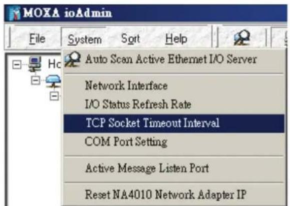
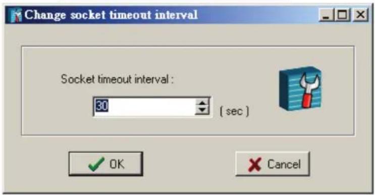
The Socket timeout interval in the System menu is used to configure the timeout for each Modbus/TCP query from the host computer to the Ethernet Network Adapter. The unit is seconds.
Watchdog Timer
The Watchdog timer function is used to monitor the Modbus/TCP connection between the Ethernet Network Adapter and the host computer. The default is "off."
When there are no queries from the host computer over a preset time (in 100 msec increments), the Ethernet Network Adapter sets all digital output and analog output values to a predefined Safe Status. The maximal value of the Timeout Value is 65535, which means 6553.5 seconds.
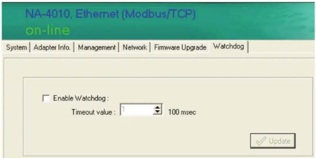
Firmware Upgrade
NA-4010's firmware can be updated via Ethernet. To upgrade the firmware, click on "Firmware Upgrade" tab.
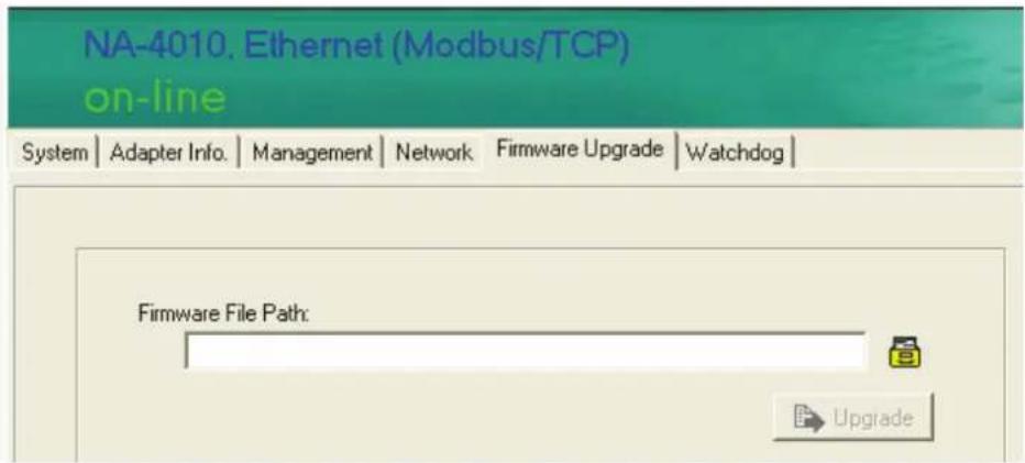
Click on the file icon and select the firmware. Press Upgrade when you're ready. During the firmware upgrade, DO NOT turn the ioLogik 4000's power off.
Exporting the System Configuration
To help you record the I/O module combination and parameters, ioAdmin can generate a text report file that can help you manage the system.
The report consists of following parts.
- Date, Time, and Firmware version
- Slice Models
- Slice Configuration
- Modbus address table
Remote Monitoring
NA-4010 Ethernet Network Adapter allows up to 8 concurrent TCP connections. The benefit is that ioAdmin still can monitor the status of the Ethernet I/O server when it's in operation.
I/O Status Refresh Rate
The parameter determines how often ioAdmin utility polls all connected I/O Servers. The default value is 50 (500 msec). To change the configuration, click I/O Status Refresh Rate under the System menu, and then adjust the data refresh rate. Note that the unit is in 10 msec increments, so if you enter 50, the refresh rate becomes 0.5 sec.
Checking NA-4010's Ethernet I/O Status via Web Browser
Entering the Web Console
The main configuration interface for the ioLogik 4000 relies on ioAdmin utility. However, for NA-4010 Ethernet Network Adapter's web console, information for basic system status is available.
Enter the IP address of the Ethernet I/O server in Internet Explorer.
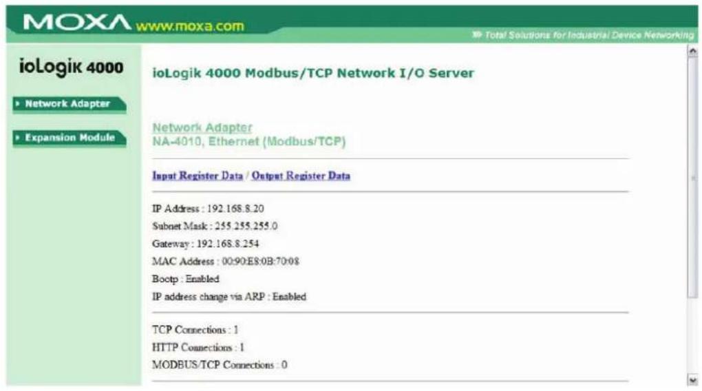
You may check network configuration status and firmware number on the homepage. Click on Expansion Module to see the information for all connected modules.
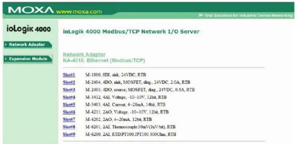
Click on the slot number to see the status of each module. The following example is for the thermocouple module.
![ioLogik 4000 Network Adapter Expansion Module ioLogik 4000 Modbus/TCP Network I/O Server Slot# M-6201, 2AI, Thermocouple:30mV(1uV/bit), RTB Configuration Parameter Data[Hex] = 00 10 Input Data[Hex] = 012C 0136 Sensor Type : K Temperature unit : Celsius Temperature Ch0 : 30.0 Temperature Ch1 : 31.0 Prev Slot Next Slot](/content/2026/05/997942/images/ce36d2299fa5b1352012ac24ca636e6216a459b3cdfc1b6e1a209bb7f17ad91e.jpg)
Configuring NA-4020/4021's RS-485/RS-232 I/O System
Setting Communication Parameters
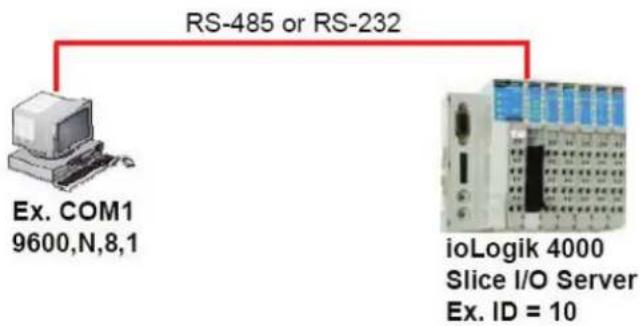
For first time users, link NA-4021's RS-232 Network Adapter to the host computer. Make sure the computer is equipped with an RS-232 communication port. For NA-4020's RS-485 Network Adapter, use a DB9 cable with correct wiring to connect to the host computer. You may need to add a Moxa multiport serial board (such as CP-132U) or USB to Serial Hub (NPort 1220) to expand the number of COM ports.
Connecting Single Serial I/O Server
flowchart
graph TD
    A["Ex. COM1\n9600,N,8,1"] -->|RS-485 or RS-232| B["i oLogik 4000\nSlice I/O Server\nEx. ID = 10"]
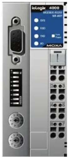
There is a DIP switch on NA-4020/4021's front panel that allows you to configure the parameters manually.
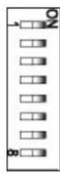
DIP Switch Configuration Table (default settings are in bold)
| No. Configuration Settings | ||
| 1-3 Baud Rate 1 2 3 | ||
| OFF OFF OFF : 1200 bpsON OFF OFF : 2400 bpsOFF ON OFF : 4800 bpsON ON OFF : 9600 bpsOFF OFF ON : 19200 bpsON OFF ON : 38400 bpsOFF ON ON : 57600 bpsON ON ON : 115200 bps | ||
| 4 Watchdog | ON: Enable | OFF: Disable |
| 5-7 CommunicationParameters | 5 6 7OFF OFF OFF : None, 8 data bits, 1 stop bitON OFF OFF : Even, 8 data bits, 1 stop bitOFF ON OFF : Odd, 8 data bits, 1 stop bitON ON OFF : None, 8 data bits, 2 stop bitsOFF OFF ON : None, 7 data bits, 2 stop bits ^1 ON OFF ON : Even, 7 data bits, 1 stop bit ^1 OFF ON ON : Odd, 7 data bits, 1 stop bit ^1 ON ON ON : None, 8 data bits, 1 stop bit | |
| 8 Modbus | protocol ON: Modbus/ASCII | OFF: Modbus/ RTU^2 |
- Only Modbus/ASCII is supported when data bits is set to 7.
- ioAdmin only be used when the Modbus protocol is set to Modbus/RTU.
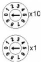
The next step is to configure the Unit ID for the I/O Server. In a Modbus/RTU/ASCII serial network, each node must have a unit ID that ranges from 01 to 99. Use a screw driver to rotate the switch and set the Unit ID. The upper switch represents the high digit, whereas the lower switch represents the low digit.
Note that the address 00, which is usually used in the Modbus/RTU/ASCII master, is reserved for broadcasts.
Linking the RS-485/232 I/O Server to ioAdmin
After you connect the RS-485/232 I/O Server to the host computer's COM port (e.g., COM2) via the DB9 cable, and the I/O server is powered on, you can start up ioAdmin. Set the communication parameters to 9600,N,8,1 for both the host computer's COM port and the serial Network Adapter.
To start ioAdmin, click on Start → Program Files → Moxa → IO Server → Utility → ioAdmin.
There are two ways to link to the RS-485/232 I/O Server. One is through Auto Search. The other is by entering the Unit ID manually.
To start the Auto Search function, click on Auto Scan Active Ethernet I/O Server under System.
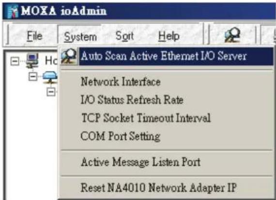
ioAdmin can automatically allocate available COM ports on the host computer and scan Unit IDs from 01 to 99 for each COM port. However, it takes longer to finish the process. A more efficient and faster method is to select
Only Search: COMx and search designated COM ports. Note that ioAdmin supports Modbus/RTU. In a Modbus/ASCII environment, configure the Network Adapter using Modbus/RTU, and then switch back to Modbus/ASCII for field operation.
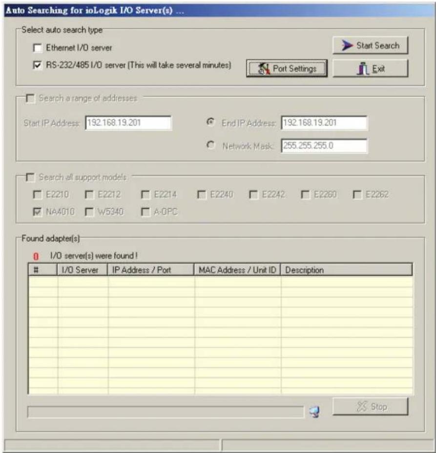
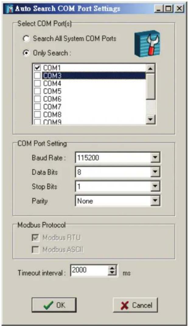
Click Port Settings to configure the COM port and baud rate, data bit stop bit, and parity for further communication. Click Start Search to search for connected RS-485 or R-232 I/O Servers.
To add RS-485/232 I/O Servers to the ioAdmin manually, click the right mouse button, and then click on ioLogik in the left ioAdmin frame. Click on NA-4021, choose the connected COM port number, and then select the Unit ID for Modbus address.
Once the RS-485/232 I/O Server is connected with ioAdmin, the following screen will appear.
![MOTA inAdmin v1.00 System Sort Help Host: [127.0.01] isLogk CON1 NA-4021 133 01: M-1800 02: M-2404 03: M-2403 04: M-3412 05: M-3403 06: M-4211 07: M-4202 08: M-6201 09: M-6208 NA-4021, RS232 (Modbus) on-line System | Adapter Info | Management | 08 01 02 03 04 05 06 07 08 09 isLogk -400B MOSFET, 24VDC, RTB isLogk -400B MOSFET, 24VDC, RTB isLogk -400B MOSFET, 24VDC, RTB isLogk -400B MOSFET, 24VDC, RTB isLogk -400B MOSFET, 24VDC, RTB isLogk -4012, 4A1, Voltage, -10~10V, 12bit, RTB Slice Description 1 M-1800 M-1800, 0D1, sink_24VDC, RTB 2 M-2404 M-2404, 4D0, sink_MOSFET, deg., 24VDC, 2.0A, RTB 3 M-2403 M-2403, 4D0, source_MOSFET, 24VDC, 0.5A, RTB 4 M-3412 M-3412, 4A1, Voltage, -10~10V, 12bit, RTB](/content/2026/05/997942/images/68c4879e24ca45ed56d6c5ef4ac8eab47b9a5de2d385ef3367ead6ebfc3c8a11.jpg)
The left frame of ioAdmin shows all I/O Servers found on the network. The upper right frame indicates the combination of all I/O modules by slot number. The lower right frame lists detailed information for installed I/O modules.
Move the mouse cursor over any I/O module to display the model name and description automatically.
At this point, your I/O Server should be up and running. The next topic explains additional ioLogik 4000 management issues. You may also jump to Chapter 4 and check the status of each I/O channel.
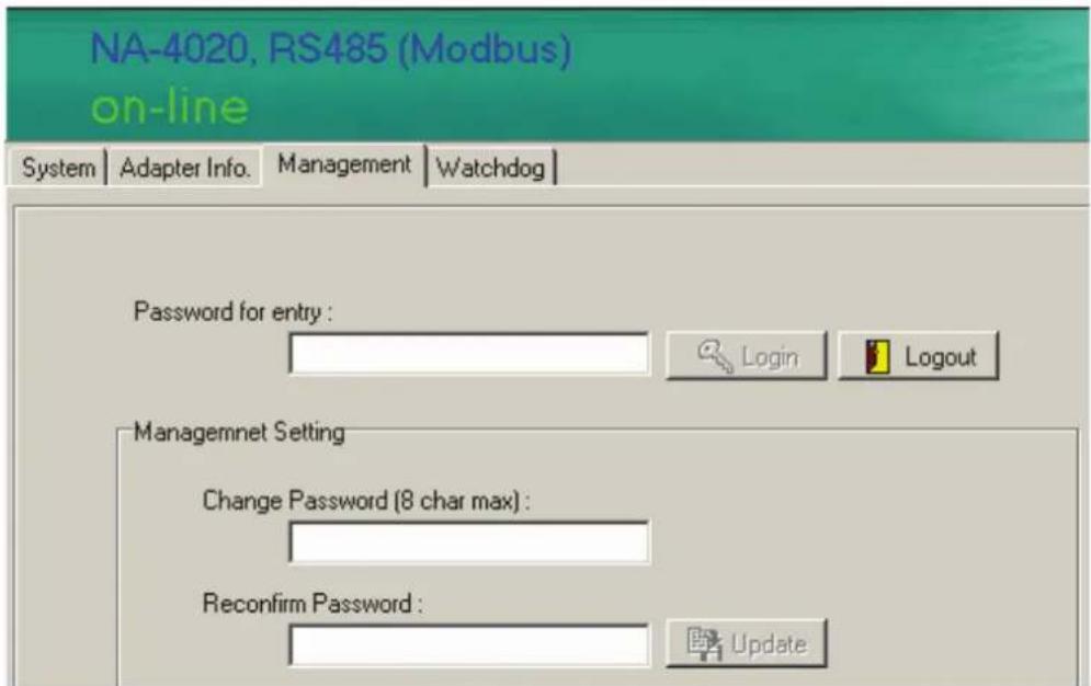
Password Protection
Watchdog configuration, Reset to Default, and Restart System are password protected. By default, the password is blank. However, you will still need to click on Login to show the Watchdog tab.
Reset to Default
The Network Adapter settings, watchdog timer setting, I/O module safety status, and temperature sensor parameters are stored in the network adapter. Right click on the target I/O server, and then click on Reset to Default to proceed. You may need to wait 10 seconds or longer. ioAdmin will reconnect the I/O Server automatically.
Note that this function requires password authorization to activate.
Baud rate: 9600
Communication parameter: N,8,1
Modbus protocol: RTU
Modbus watchdog: disable
* The above parameters are set by the Network Adapter's DIP switch.
Watchdog timeout: 5 sec (50 x 100ms)
Password: (Empty)
* The above parameters are set by software.
Restarting the System
In general, your don't need to restart the I/O server when changing I/O module configurations. However, when the I/O Server indicates an I/O error, you may use this function to restart the I/O Server system remotely.
Right click on the target I/O server and then click on Restart System to proceed. You may need to wait 10 seconds or longer. ioAdmin will reconnect to the I/O Server automatically.
Note that this function requires password authorization to activate.
Deleting an I/O Server from the List
Sometimes too many I/O Servers appear in the left ioAdmin frame. To delete the I/O Server from the list for easier management, right click on the target I/O Server. Click on Disconnect, and then click on Delete I/O Server. The target I/O Server will be removed from the list.
Note that this function requires disconnected from the ioLogik to activate.
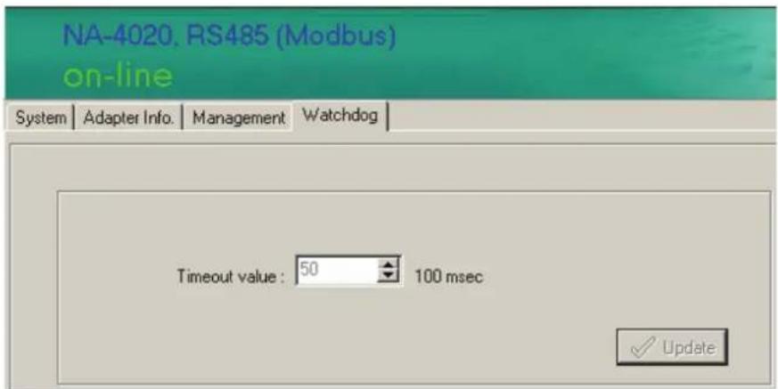
Watchdog Timer
The Watchdog timer monitors the Modbus/RTU or Modbus/ASCII connection between the Network Adapter and the host computer. The default is off.
When there is no query from the host computer over a preset time (in 100 msec increments), the Network Adapter will set all digital output and analog output values to a predefined Safe Status. Whether or not the Network Adapter is operational and ready for normal operation depends on the host computer. The maximal value of the Timeout Value is 65535, which means 6553.5 seconds.
Firmware Update
Firmware updates for NA-4020 and NA-4021 are not available to end users. If you need to update the firmware, please contact your local distributor for service.
I/O Status Refresh Rate
This parameter determines how often the ioAdmin utility polls all connected I/O Servers. The default value is 50 (500 msec). To change the configuration, click on Data Refresh Rate in the System menu, and then adjust the data refresh rate. Note that the units are in 10 msec increments, so if you enter 50, the refresh rate changes to 0.5 sec.
Modbus Address Mapping
Finding a Modbus Address for I/O Channels
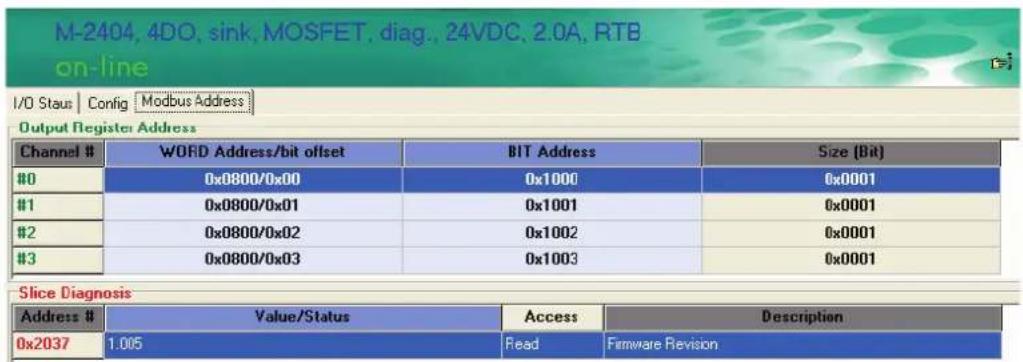
The Modbus Address for each I/O channel is arranged dynamically by the Network Adapter according to the slot sequence and the type of I/O module. Changing Ethernet Network Adapter to RS-485 or RS-232 Network Adapters will not change the Modbus address mapping.
The Modbus Address mapping for I/O module can be found on "Modbus Address" tab.
![M-2404, 4DO, sink, MOSFET, diag., 24VDC, 2.0A, RTB on-line I/O Staus | Contig | Modbus Address Output Register Address Channel # WORD Address/bit offset BIT Address Size [Bit] #0 0x0800/0x00 0x1000 0x0001 #1 0x0800/0x01 0x1001 0x0001 #2 0x0800/0x02 0x1002 0x0001 #3 0x0800/0x03 0x1003 0x0001 Slice Diagnosis Address # Value/Status Access Description 0x2037 1.005 Read Firmware Revision](/content/2026/05/997942/images/f9afe877742a311b917f9abdbb0f337f1a23700d87cf17e4bad6f78df9eaa89d.jpg)
There are three columns for Modbus Address. According to the Modbus standard, there are two methods to access I/O channel. One is access by Register, and the other is by Coil. Each I/O channel can be accessed via the Register or Coil method.
For more information, refer to the Modbus protocol specifications.
Exporting Modbus Address Settings
Modbus Addresses for I/O channels are required when you want to access the I/O status via SCADA software. However, it's not easy to memorize all of the addresses for each I/O channel. for this reason, ioAdmin allows you to export a text file containing the installed I/O modules and their Modbus addresses. The following example is an exported system configuration file.
- Modbus address table
| Slot No. | Channel No. | I/O type | Modbus Addr.(WORD) | Modbus Addr.(BIT) | I/O Data Length |
| 01 | 00 | Input | 0x0000/0x00 | 0x0000 | 0x0010 |
| 01 | 01 | Input | 0x0001/0x00 | 0x0010 | 0x0010 |
| 01 | 02 | Input | 0x0002/0x00 | 0x0020 | 0x0010 |
| 01 | 03 | Input | 0x0003/0x00 | 0x0030 | 0x0010 |
| 02 | 00 | Input | 0x0004/0x00 | 0x0040 | 0x0010 |
| 02 | 01 | Input | 0x0005/0x00 | 0x0050 | 0x0010 |
| 03 | 00 | Input | 0x0006/0x00 | 0x0060 | 0x0001 |
| 03 | 01 | Input | 0x0006/0x01 | 0x0061 | 0x0001 |
| 03 | 02 | Input | 0x0006/0x02 | 0x0062 | 0x0001 |
| 03 | 03 | Inupt | 0x0006/0x03 | 0x0063 | 0x0001 |
| 03 | 04 | Input | 0x0006/0x04 | 0x0064 | 0x0001 |
In this chapter, we describe the common features related to using ioAdmin to configure I/O modules.
The following topics are covered in this chapter:
Overview
☐ On-Line Wiring Guide
□ Digital Input Module
□ Digital Output Module
Safe Status
□ Analog Input Module
☐ Analog Output Module
Safe Status
□ Temperature Sensing Modules
RTD
Thermocouple
Overview
This Chapter describes common features of ioAdmin for configuring I/O modules.
On-Line Wiring Guide
ioAdmin has a graphical interface that features the "What You See Is What You Install" philosophy. The ioLogik 4000 is easy-to-use, and ioAdmin comes with an on-line I/O wiring guide that makes your job easier than ever. Use the mouse to move the cursor over any of the I/O modules and then click on the right mouse button to display a "Wiring Guide".
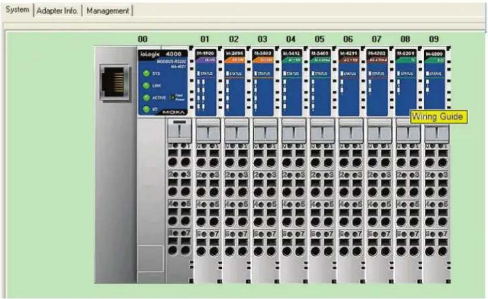
Click on the wiring guide to show a help file for that model.
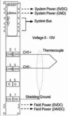
M-6201 2 analog input, Thermocouple, removable terminal block
System wiring
Input Specification
| Sensor types | : Type J/K/T/E/R/S/B/N/L/U/C/DmV input 10uV/bit, 1uV/bit, 2uV/bit |
| Data format | : 16 bit integer (2 s compliment) |
| Resolution | : 0.1C / 10m ohm |
| Accuracy | : +/- 0.1%, FSR @ 25C+/- 0.3%, FSR @ 0C, 60C |
| Input impedance | : |
| Conversion time | : 200m sec. / all channel |
| Diagnostic | : Range over (if range over, data=Dx8000) |
General Specification
| Power dissipation | : Max. 70mA @ 5.0VDC |
| Isolation | : I/O to logic: 2kVrms optical isolation |
| Wiring | : I/O cable max. AWG14 |
Digital Input Module
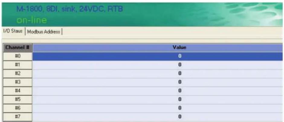
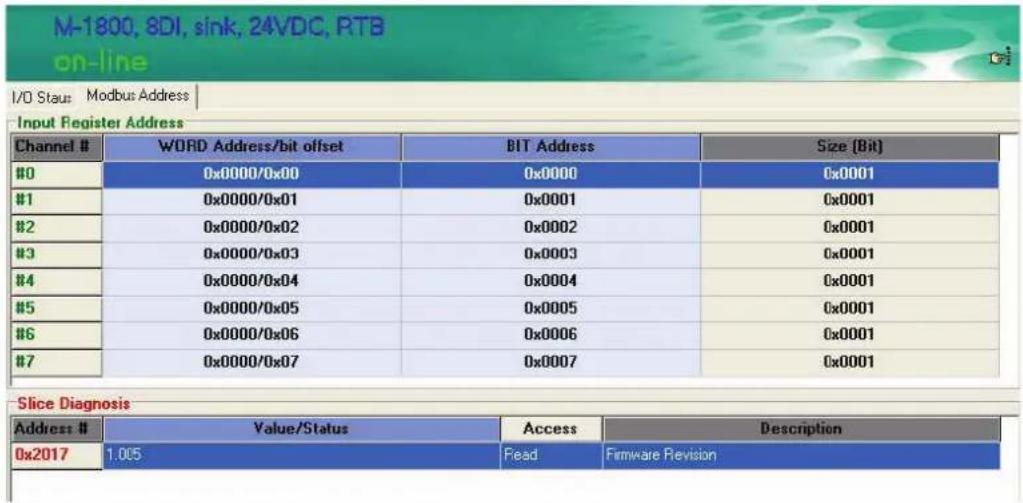
ioAdmin can monitor the status of each digital input channel. We use M-1800 to illustrate. To check the DI channel status, click on the I/O module in main page to show the I/O status on the "I/O Status" tab.
To check the Modbus Address, click on the "Modbus Address" tab.
| Related Models Digital Input | |
| M-1800 8 DI, sink, 24 | VDC, RTB |
| M-1801 8 DI, source, | 24 VDC, RTB |
| M-1600 16 DI, sink, 24 | VDC, RTB |
| M-1601 | 16 DI, source, 24 VDC, 20-pin |
| M-1450 4 DI, 110 VAC, | RTB |
| M-1451 4 DI, 220 VAC, | RTB |
Digital Output Module
ioAdmin can monitor the status of each digital output channel. We use M-2404 to illustrate. To check the DI channel status, click on the I/O module in the main page. You'll see the I/O status on the "I/O Status" tab.
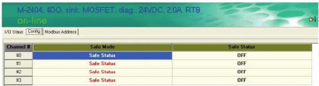
To check the Modbus Address, click on the "Modbus Address" tab.
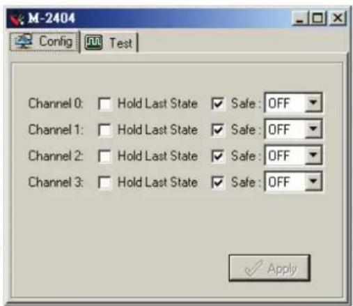
Safe Status
The digital output channel can be set to safe status when the following situations occur.
- Modbus watchdog is activated
- I/O error status
You may set the digital output status to following situations.
- Hold last state
- ON or OFF
Note that the configuration applies to all channels within the module.
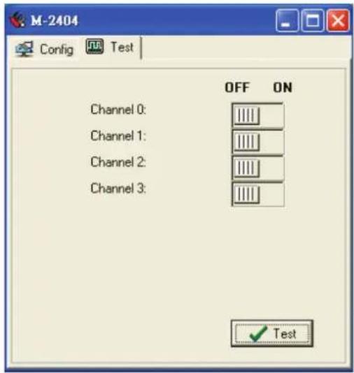
You can test to make sure the digital output channel works over the network. Click on the "Test" tab in the "Config" page. Press the switch, and then press "Test." At this point, you can change the status of the digital output point.
| Related Models Digital Input | |
| M-2800 | 8 DO, sink, MOSFET, 24 VDC, 0.5A, RTB |
| M-2801 8 DO, source, MOSFET, 24 VDC, 0.5A, RTB | |
| M-2600 | 16 DO, sink, MOSFET, 24 VDC, 0.3A, 20pin |
| M-2601 | 16 DO, source, MOSFET, 24 VDC, 0.3A, 20pin |
| M-2450 4 DO, Relay, | 230 VAC, 24VDC, 2.0A, RTB |
Analog Input Module
ioAdmin can monitor the status of each analog input channel. We'll use M-3412 to illustrate. To check the status of the DI channel, click on the I/O module in the main page. The I/O status is located on the "I/O Status" tab.
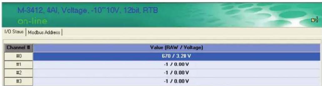
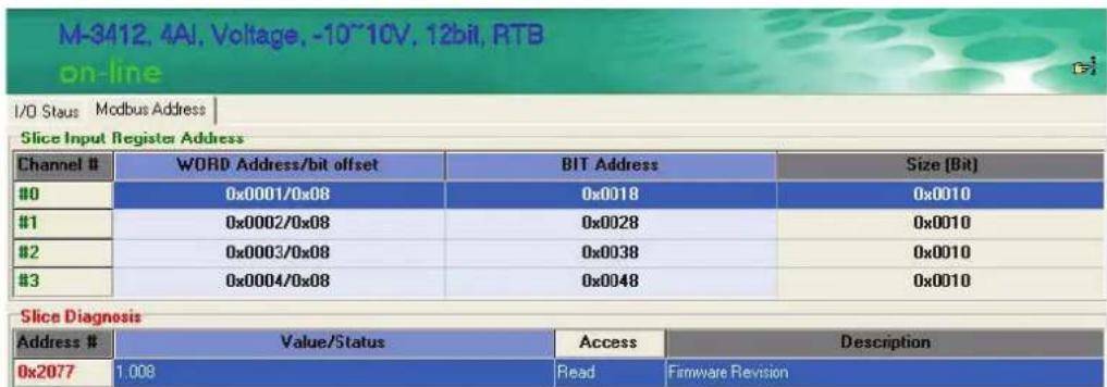
To check the Modbus Address, click on the "Modbus Address" tab.
| Related Models Digital Input | |
| M-3802 | 8 AI, Current, 4-20 mA, 12-bit, RTB |
| M-3810 | 8 AI, Voltage, 0-10V, 12-bit, RTB |
Analog Output Module
This section describes how to configure an analog output module. We'll use M-4211 to illustrate. To check the status of an analog output channel, click on the I/O module in the main page. You'll see the I/O status on the "I/O Status" tab.
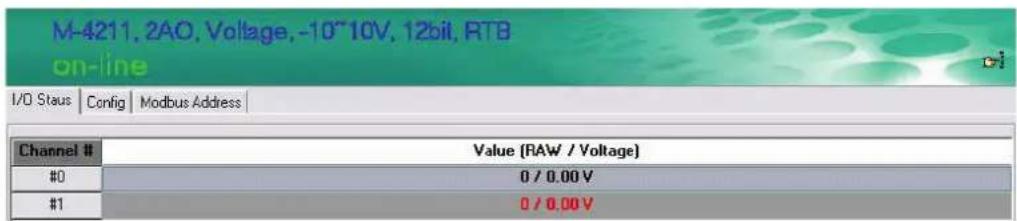
To check the Modbus Address, click on "Modbus Address" tab.
![M-4211, 2AO, Voltage, -10~10V, 12bit, RTB on-line I/O Staus | Config Modbus Address | Output Register Address Channel # WORD Address/bit offset BIT Address Size [Bit] #0 0x0801/0x00 0x1010 0x0010 #1 0x0802/0x00 0x1020 0x0010 Slice Diagnosis Address Value/Status Access Description 0x20B7 1.008 Read Firmware Revision](/content/2026/05/997942/images/9406e8f8749d712ec9e2b881330345bf91ea9066df330a8a3b14890819098e3f.jpg)
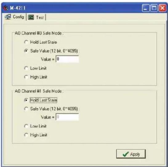
Safe Status
The analog output channel can be set to safe status when the following situations occur.
- Modbus watchdog is activated
- I/O error status
You may set the analog output status to the following situations.
- Hold last state
- Safe value
- Low limit
- High limit
Low Limit represents the lowest value for the analog out module. For a 0 to 10V analog output module, the Low Limit is 0V.
High Limit represents the highest value for the analog output module. For a 0 to 10V analog output module, the High Limit is 10V.
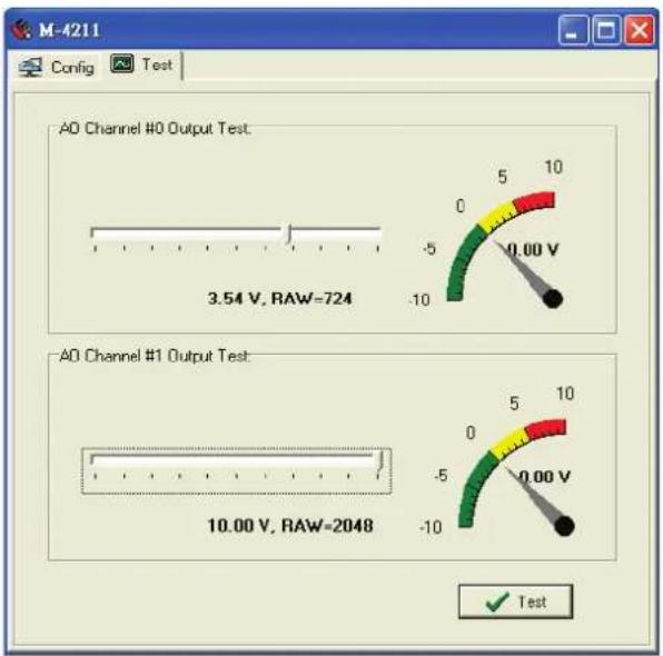
You may test if the analog output channel really works over the network. Click on the "Test" tab on the "Config" page. Scroll the output level, and then press "Test." At this point, you can change the level of the analog output point.
| Related Models Analog Output | |
| M-4402 | 4 AO, 4-20 mA, 12-bit, RTB |
| M-4410 | 4 AO, Voltage, 0-10V, 12-bit, RTB |
Temperature Sensing Modules
The ioLogik 4000 provides RTD (Resistance Temperature Detector) and TC (Thermocouple) temperature sensing modules.
RTD
To check the temperature status, click on the I/O module from the main page. The temperature is on the "I/O Status" tab. When the sensor is not connected or the wiring is broken, the value is "0x8000".
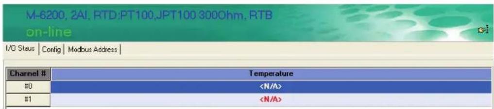
To check the Modbus Address, click on the "Modbus Address" tab.
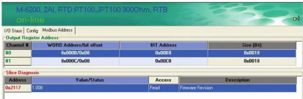
The RTD module supports different kinds of temperature sensor. To configure the sensor type, click on config.
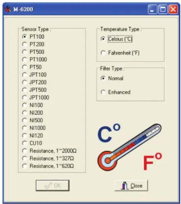
On this page, you may set up the sensor types and temperature unit. Note that the configuration applies to all channels in the same module. The related model is M-6200. The FilterType represents different sampling times. In Normal mode, the conversion time is about 200 msec. In Enhanced mode, the conversion time will be about double, or around 400 msec.
Thermocouple
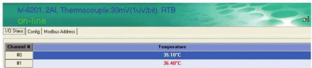
To check the temperature status, click on the I/O module from the main page. You'll see the temperature on the "I/O Status" tab.
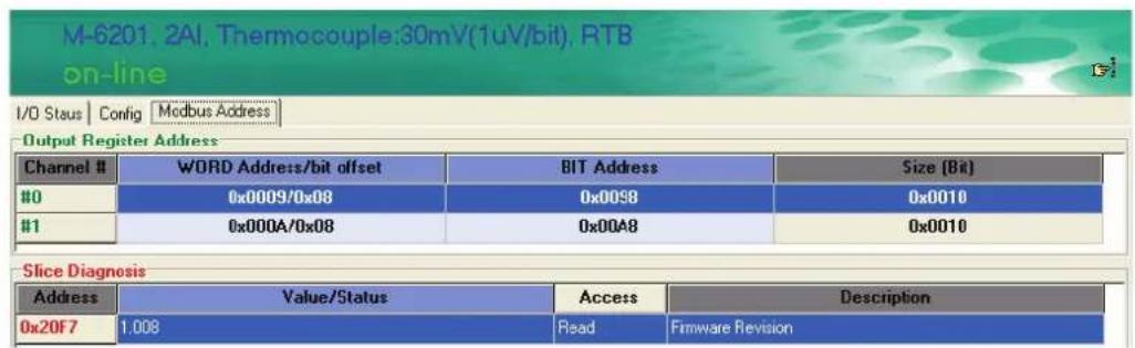
To check the Modbus Address, click on the "Modbus Address" tab.
The thermocouple module supports different kinds of temperature sensor. To configure the sensor type, click on config.
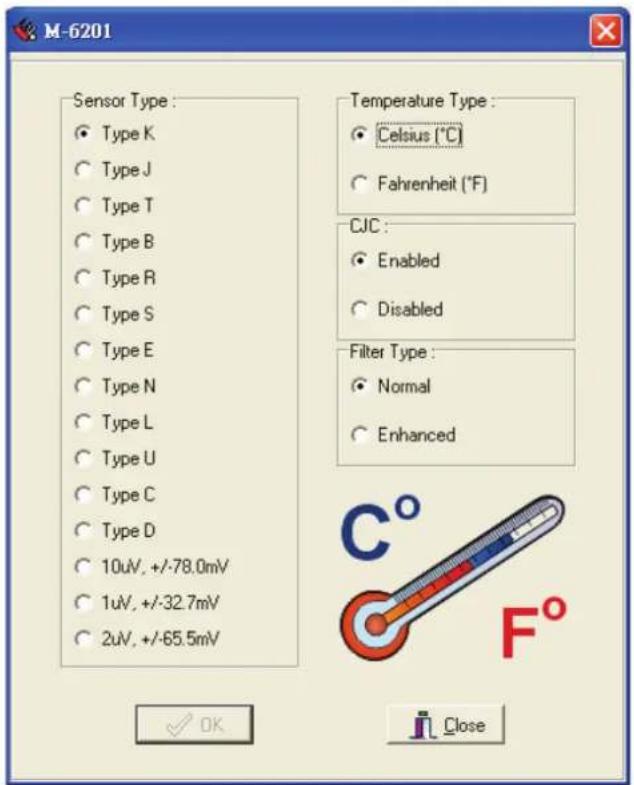
On this page, you may set up the sensor types and the temperature unit. Note that the configuration applies to all channels in the same module. The related model is M-6201.
The FilterType represents the different sampling times. In Normal mode, the conversion time is about 200 msec. In Enhanced mode, the conversion time will be about double, or around 400 msec. The thermocouple temperature sensor is noise sensitive. Using Enhanced Mode can increase stability of the readings. CJC should always be enabled.
The following topics are covered in this chapter:
Overview
□ MXIO Function Groups
Overview
What is MXIO DLL Library?
MXIO DLL Library is a Windows library especially designed for programmers who are not familiar with Modbus protocol, but who need to create applications to get real world temperature, data, and on/off control signals.
MXIO DLL supports Visual Basic, Visual C++, and Borland C++ Builder.
How to install MXIO DLL Library
MXIO DLL Library comes with the ioAdmin software utility. It is installed in the directory Start → Programs →
Moxa → IO Server → Library. Refer to MXIO DLL help for more details.
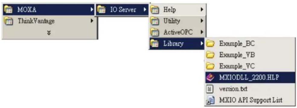
MXIO Function Groups
| 1. System CommandsRS-485/RS-232 I/O ConnectCommandsMXSIO_OpenCommPortMXSIO_CloseCommportMXSIO_ConnectMXSIO_DisconnectEthernet I/O Connect CommandsMXEIO_InitMXEIO_ExitMXEIO_ConnectMXEIO_DisconnectMXEIO_CheckConnectionGeneral CommandsMXIO_GetDllVersionMXIO_GetModuleType2. Modbus Command SetsMXIO_ReadCoilsMXIO_WriteCoilsMXIO_ReadRegsMXIO_WriteRegs | 3. Direct I/O Command SetsDigital Input CommandsDI_ReadsDI_ReadDigital Output CommandsDO_ReadsDO_ReadDO_WritesDO_WriteAnalog Input CommandsAI_ReadsAI_ReadAnalog Output CommandsAO_ReadsAO_ReadAO_WritesAO_WriteRTD CommandsRTD_ReadsRTD_ReadThermocouple CommandsTC_ReadsTC_Read | 4. Special Commands for the ioLogik 4000Adp4K_ReadFirmwreRevisi onAdp4K_ReadFirmwareDateAdp4K_ReadSlotAmountAdp4K_ReadStatusAdp4K_ReadAlarmedSlot |
The following topics are covered in this appendix:
□ Port Pinout Diagrams
Ethernet Port Pinouts
Serial Port Pinouts
☐ Ethernet Cable Wiring Diagrams
Port Pinout Diagrams
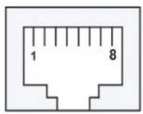
Ethernet Port Pinouts
| Pin Signal | |
| 1 Tx+ | |
| 2 Tx- | |
| 3 Rx+ | |
| 6 Rx- | |
Serial Port Pinouts
NA-4020 RS-485 Network Adapter Pin Assignment.
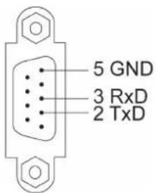
NA-4021 RS-232 Network Adapter Pin Assignment
Ethernet Cable Wiring Diagrams
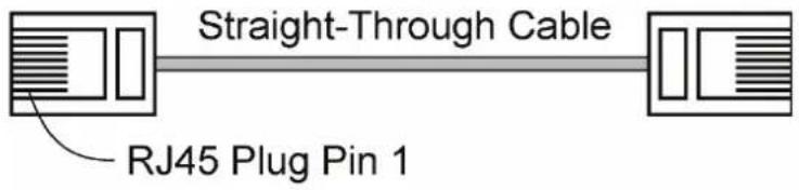
Cable Wiring
3 3
6 6
1 1
2 2
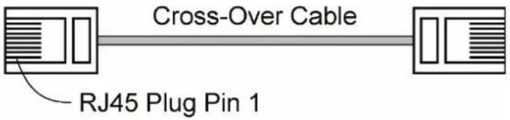
Cable Wiring
3 1
6 2
1 3
2 6
- ioLogik 4000 Series User's Manual
- Copyright Notice
- Trademarks
- Disclaimer
- Technical Support Contact Information
- Moxa Americas
- Moxa Europe
- Moxa India
- Moxa China (Shanghai office)
- Moxa Asia-Pacific
- Hardware Installation 2-1
- Getting Started 3-1
- Configuring I/O Modules.... 4-1
- ioLogik 4000 System Overview
- Package Contents
- Network Adapter
- I/O Module
- Product Features
- Product Specifications
- □ System Architecture
- □ Connecting the Network Adapter to I/O Modules
- □ Connecting the Power System
- □ Connecting to the Network
- □ LED Indicators
- ☐ When to Use the Power Expansion Module
- □ When to Use the Field Power Distributor
- ☐ When to Use the Potential Distributor
- □ Safety Notes
- System Architecture
- Connecting the Network Adapter to I/O Modules
- Appearance
- Installing I/O Modules on a DIN-Rail
- Removing I/O Modules from a DIN-Rail
- Installing an RTB (Removable Terminal Block)
- Installing the RTB on the I/O module
- Connecting the Power System
- Connecting to the Network
- NA-4010 Ethernet Network Adapter
- NA-4020 RS-485 Network Adapter
- NA-4021 RS-232 Network Adapter
- LED Indicators
- LED Indicators for Network Adapters
- LED Indicators for I/O Modules
- When to Use the Power Expansion Module
- Power Off Sequence
- Power Up Sequence
- When to Use the Field Power Distributor
- When to Use the Potential Distributor
- Safety Notes
- Installation and Cabling Precautions
- Operating Precautions
- ATTENTION
- □ Installing ioAdmin Utility
- ☐ Configuring the NA-4010 Ethernet I/O System
- □ Checking NA-4010's Ethernet I/O Status via Web Browser
- ☐ Configuring NA-4020/4021's RS-485/RS-232 I/O System
- Modbus Address Mapping
- Installing ioAdmin Utility
- Installing ioAdmin from website:
- Configuring the NA-4010 Ethernet I/O System
- Initializing the IP Address
- Linking the Ethernet I/O System to ioAdmin
- I/O Server IP Address / Port MAC Address / Unit ID Description
- Slice Description
- Password Protection
- Reset to Default
- Restart System
- Deleting an I/O Server from the List
- Network
- TCP Socket Timeout Interval
- Watchdog Timer
- Firmware Upgrade
- Exporting the System Configuration
- Remote Monitoring
- I/O Status Refresh Rate
- Checking NA-4010's Ethernet I/O Status via Web Browser
- Entering the Web Console
- Configuring NA-4020/4021's RS-485/RS-232 I/O System
- Setting Communication Parameters
- Linking the RS-485/232 I/O Server to ioAdmin
- Restarting the System
- Firmware Update
- Finding a Modbus Address for I/O Channels
- Exporting Modbus Address Settings
- Overview
- On-Line Wiring Guide
- M-6201 2 analog input, Thermocouple, removable terminal block
- Input Specification
- General Specification
- Digital Input Module
- Digital Output Module
- Safe Status
- Analog Input Module
- Analog Output Module
- Temperature Sensing Modules
- RTD
- Thermocouple
- MXIO Function Groups
- Port Pinout Diagrams
- Ethernet Port Pinouts
- Serial Port Pinouts
Brand : Moxa
Model : NA-4010
Category : Network Card/Adapter