
IC485AI - Audio/video converter ATEN - Free user manual and instructions
Find the device manual for free IC485AI ATEN in PDF.


| Product Type | Audio/Video Converter |
| Brand | ATEN |
| Model | IC485AI |
| Input Interface | Composite video (RCA), stereo audio (RCA) |
| Output Interface | Composite video (RCA), stereo audio (RCA) |
| Video Format | NTSC/PAL auto-sensing |
| Audio Format | Analog stereo |
| Maximum Resolution | 480i (standard definition) |
| Dimensions (W x D x H) | 100 x 60 x 25 mm |
| Weight | 0.15 kg |
| Power Supply | 5V DC, 1A (via USB or adapter) |
| Power Consumption | < 2W |
| Operating Temperature | 0°C to 50°C |
| Storage Temperature | -20°C to 60°C |
| Humidity | 20% to 80% RH |
| Housing Material | Metal |
| Color | Black |
| LED Indicators | Power, Signal |
| Plug and Play | Yes |
| Compliance | CE, FCC |
| Included Accessories | User manual, power adapter, audio/video cables |
| Maintenance | Wipe with dry cloth, avoid liquids |
| Safety | Use only supplied power adapter, keep away from water |
| Spare Parts and Repairability | No user-serviceable parts; contact ATEN support for repairs |
Frequently Asked Questions - IC485AI ATEN
User questions about IC485AI ATEN
0 question about this device. Answer the ones you know or ask your own.
Ask a new question about this device
Download the instructions for your Audio/video converter in PDF format for free! Find your manual IC485AI - ATEN and take your electronic device back in hand. On this page are published all the documents necessary for the use of your device. IC485AI by ATEN.
USER MANUAL IC485AI ATEN
STATEMENT: This equipment has been tested and found to comply with the limits for a Class B digital service, pursuant to Part 15 of the FCC rules. These limits are designed to provide reasonable protection against harmful interference in a residential installation. Any changes or modifications made to this equipment may void the user's authority to operate this equipment. This equipment generates, uses, and can radiate radio frequency energy. If not installed and used in accordance with the instructions, may cause harmful interference to radio communications. However, there is no guarantee that interference will not occur in a particular installation.
If this equipment does cause harmful interference to radio or television reception, which can be determined by turning the equipment off and on, the user is encouraged to try to correct the interference by one or more of the following measures:
◆ Reorient or relocate the receiving antenna.
◆ Increase the separation between the equipment and receiver.
- Connect the equipment into an outlet on a circuit different from that to which the receiver is connected.
- Consult the dealer or an experienced radio/TV technician for help.
FCC Caution: Any changes or modifications not expressly approved by the party responsible for compliance could void the user's authority to operate this equipment.
This device complies with Part 15 of the FCC Rules. Operation is subject to the following two conditions:
(1) this device may not cause harmful interference, and
(2) this device must accept any interference received, including interference that may cause undesired operation.
♦ KCC Statement
This product is RoHS compliant.

IC485AI User Manual
Online Registration
You can register your product at our online support center:
International http://support.aten.com
Online Support
International
| Email Support support@aten.com | ||
| Online Support | Technical Support http://support.aten.com | |
| Troubleshooting Documentation Software Updates | http://www.aten.com | |
North America
| Email Support support@aten-usa.com | ||
| Online Technical Support | Troubleshooting Documentation Software Updates | http://www.aten-usa.com/support |
| Telephone Support 1-888-999-ATEN ext 49881-949-428-1111 | ||
Telephone Support
For telephone support, call this number:
| International 886-2-8692-6959 | |
| China 86-400-810-0-810 | |
| Japan 81-3-5615-5811 | |
| Korea 82-2-467-6789 | |
| North America 1-888-999-ATEN ext 49881-949-428-1111 |
Package Contents
The RS232 / RS485 Interface Converter package contains the following items:
◆ 1 IC485AI Bidirectional Isolated Converter
◆ 1 Power Adapter
◆ 1 User Manual
Check to make sure that all the components are present and that nothing got damaged in shipping. If you encounter a problem, contact your dealer.
Read this manual thoroughly and follow the installation and operation procedures carefully to prevent any damage to the unit, and/or any of the devices connected to it.
* Features may have been added to the IC485AI since this manual was printed. Please visit our website to download the most up-to-date version of the manual.
Copyright © 2020 ATEN® International Co., Ltd.
Manual Part No. PAPE-0194-100
Manual Date: 2020-07-13
ATEN and the ATEN logo are trademarks of ATEN International Co., Ltd. All rights reserved. All other trademarks are the property of their respective owners.
Although RS-232 serial ports are found on almost every computer, because of their slow transmission speeds, limited range, and limited networking capabilities, they are not an effective solution for industrial strength long distance communications systems.
Systems based on the RS-422 and RS-485 standards, on the other hand, are not subject to the RS-232 limitations because they utilize different voltage lines for the data and control signals.
The IC-485AI Isolated Converter is a bidirectional converter that transparently converts RS-232 signals to RS-422 / RS-485 signals (and vice versa), thus permitting the creation of reliable long distance data communications systems using standard computer hardware.
The IC-485AI provides Point-to-Point; Multidrop; and Simplex operations over distances of up to 1200 m (4000 ft.). Designed with built in optocouplers for exceptional signal isolation, plus transformers for excellent power isolation, this extremely reliable isolated converter enhances the quality of data communications at the same time that it protects your equipment from electrical surges of up to 2000 volts.
Features
◆ Automatic internal RS-485 bus supervision
- No external flow control signals for RS-485 required
◆ Transient suppression on RS-485 data lines
◆ LEDs for easy status monitoring
◆ Minimum 2000V isolation protection
◆ Up to 115.2 Kbps data throughput
◆ DCE / DTE selectable
- Point-to-Point; Multidrop; and Simplex operating modes
- Four wire full duplex; two wire half duplex
♦ Cable distance of up to 1200 m (4000 ft.)
◆ Compact size
Components
Top view:
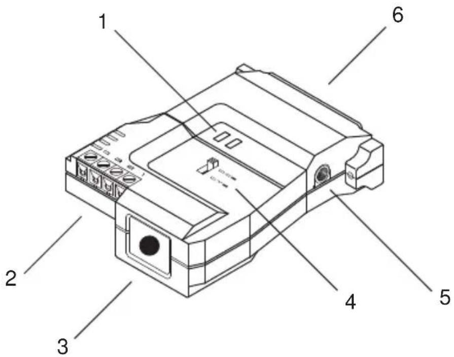
- Status LEDs
◆ RTS: Lights to indicate that RTS has been pulled high.
- TxD: Flashes when data transmission occurs.
- RS-422 / RS-485 Terminal Block
- Grounding Tab
- DCE /DTE Selection Switch
If the IC-485AI is going to be plugged into a DTE device, the switch must be set to DCE, and vice versa.
- Power Jack
The cable from the Power Adapter plugs in here.
- RS-232 DB-25 Female Connector
Bottom View:
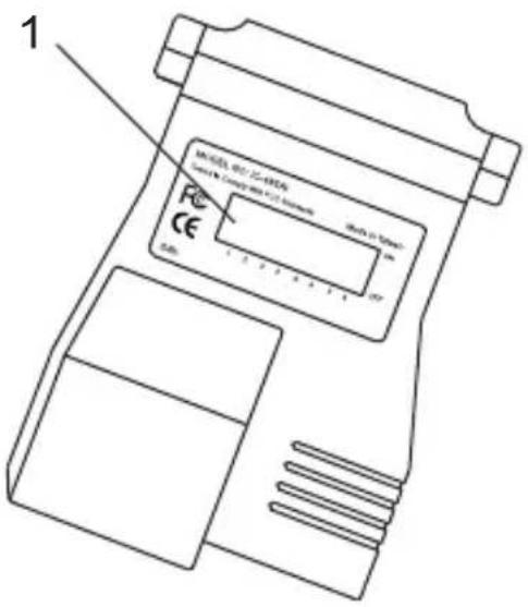
1. DIP Switch
This eight segment DIP Switch, located on the unit's bottom panel, is used to configure the switch's operating parameters.
The IC-485AI's settings for Baud Rate, Data Format, and RS-422 / RS-485 Mode are configured by setting the eight segment DIP Switch located on its bottom panel
Note: When you change any of the DIP Switch settings, you must reset the device by powering it off, then powering it on again.
◆ SW 1-3: Baud Rate
| Baud Rate SW1 SW2 SW3 | ||
| 1200 ON ON ON | ||
| 2400 OFF ON ON | ||
| 4800 ON OFF ON | ||
| 9600 OFF OFF ON | ||
| 19200 ON ON OFF | ||
| 38400 OFF ON OFF | ||
| 57600 ON OFF OFF | ||
| 115200 OFF OFF OFF |
Note: 1. The Baud Rate must be the same for all units on the installation.
- The default is 9600 bps.
◆ SW 4: Reserved
◆ SW 5-6: Data Format
These two switch segments configure the bit settings for Start, Data, Parity, and Stop.
| Data Format (bits) $W5 SW6 | ||
| 9 | O | N |
| 10 OFF ON | ||
| 11 ON OFF | ||
| 12 OFF OFF | ||
O
Note: The default is 10 bits (1 Start; 8 Data; 0 Parity; 1 Stop). Unless you have a special reason to change this, we recommend that you leave it as is. If you do change it, however, all the units on the installation must be changed to match.
- SW 7-8: RS-422 / RS-485 Operating Mode
SW7 determines whether the unit operates as an RS-422 or RS-485 converter.
- As an RS-422 converter, SW8 determines whether the unit is configured for Primary or Secondary operation.
As an RS-485 converter, SW8 determines whether the unit operates in RTS Control Mode or Auto Send Data Mode.
Operating modes are discussed in detail in the next section and on p.15
Note: RS-422 is used for 4 wire hookups; RS-485 is used for 2 wire hookups.
| Operating Mode SW7 SW8 | ||
| RS-422 Primary ON ON | ||
| RS-422 Secondary | OFF | ON |
| RS-485 Auto Send Data Mode | ON | OFF |
| RS-485 RTS Control Mode | OFF | OFF |
The IC-485AI supports three operating modes: Point-to-Point; Multidrop; and Simplex. Point-to-Point and Multidrop can be configured for Full or Half Duplex. Each of the operating modes is explained below.
Point-to-Point
A Point-to-Point configuration is one in which two devices, located at two different places are linked for communication by a pair of IC-485AI units. There are two configurations: Point-to-Point Full Duplex, and Point-to-Point Half Duplex.
1. Point-to-Point 4 Wire Full Duplex
- Point-to-Point Full Duplex uses reverse four wire cabling, as shown in the diagram below.
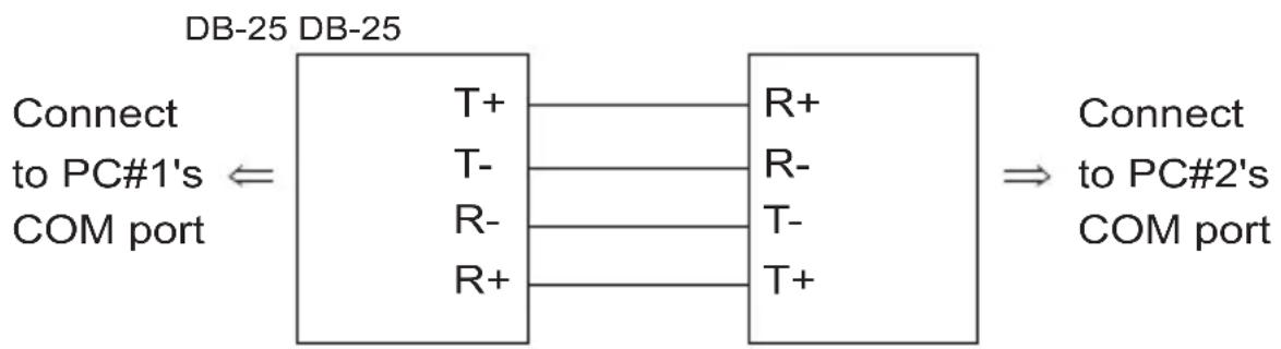
flowchart
graph LR
    A["DB-25 DB-25"] --> B["T+"]
    A --> C["R+"]
    A --> D["T-"]
    A --> E["T-"]
    A --> F["R-"]
    A --> G["R+"]
    H["COM port"] --> I["T+"]
    H --> J["R+"]
    H --> K["T-"]
    H --> L["T-"]
    H --> M["T+"]
    N["Connect to PC#1's"] <--> O["DB-25 DB-25"]
    P["Connect to PC#2's"] --> Q["DB-25 DB-25"]
    R["COM port"] --> S["DB-25 DB-25"]
- For both IC-485AI units, set the unit to DCE or DTE depending on what type of device the IC-485AI will plug into (if it will plug into a DCE device, configure it for DTE, and vice versa)
- Set SW7 and SW8 ON for both units. They are now configured for RS-422 Primary operation.
2. Point-to-Point 2 Wire Half Duplex
- Point-to-Point Half Duplex uses straight through two wire cabling, as shown in the diagram below.
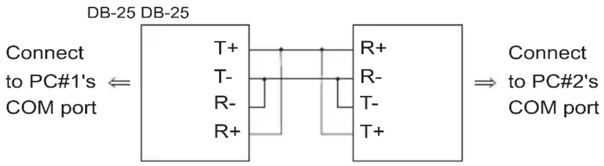
flowchart
graph LR
    A["DB-25 DB-25"] --> B["Connect to PC#1's COM port"]
    B --> C["T+"]
    B --> D["T-"]
    B --> E["R-"]
    B --> F["R+"]
    C --> G["R+"]
    D --> H["R-"]
    E --> I["T-"]
    F --> J["T+"]
    G --> K["Connect to PC#2's COM port"]
    H --> K
    I --> K
    J --> K
- For both IC-485AI units, set the unit to DCE or DTE depending on what type of device the IC-485AI will plug into (if it will plug into a DCE device, configure it for DTE, and vice versa).
- Set SW7 OFF and SW8 ON for both units. They are now configured for RS-485 Auto Send Data Mode (see p. 15 for RS-485 operation details).
Multidrop
A Multidrop configuration is one in which more than two devices are linked for communication using several IC-485AI units. One of the devices that one of the IC-485Als connects to is designated as the Primary device. All the remaining devices that the rest of the IC-485Als connect to are designated as Secondary devices. Up to 31 Secondary devices can be connected. There are two configurations: Multidrop Full Duplex and Multidrop Half Duplex.
1. Multidrop Full Duplex
- Multidrop Full Duplex uses reverse four wire cabling, to link all the connected IC-485AI units:
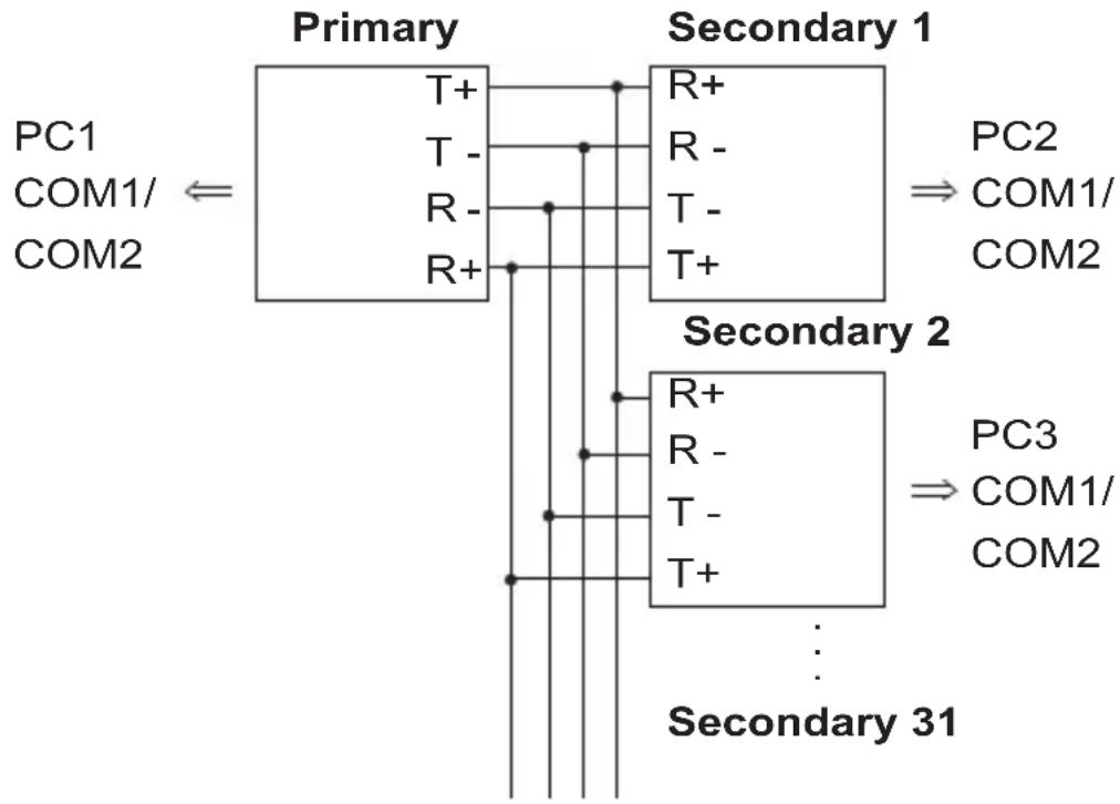
flowchart
graph TD
    A["PC1"] --> B["Primary"]
    C["COM1/COM2"] <-- B
    B --> D["T+"]
    B --> E["T-"]
    B --> F["R-"]
    B --> G["R+"]
    D --> H["Secondary 1"]
    E --> H
    F --> I["Secondary 1"]
    G --> I
    H --> J["PC2"]
    H --> K["COM1/COM2"]
    I --> L["PC3"]
    I --> M["COM1/COM2"]
    N["Secondary 2"] --> O["Secondary 31"]
    P["PC3"] --> Q["Secondary 31"]
- For all IC-485AI units, set the unit to DCE or DTE depending on what type of device the IC-485AI will plug into (if it will plug into a DCE device, configure it for DTE, and vice versa).
- For the Primary unit, set SW7 ON; set SW8 ON (RS-422 Primary mode).
- For all of the Secondary units, set SW7 ON; set SW8 OFF (RS-422 Secondary mode).
Note: 1. No more than 31 Secondary units can be connected.
2. When any of the Secondary units transmits data, none of the other Secondary units may transmit. RTS for all other Secondary units must be pulled low.
2. Multidrop Half Duplex
- Multidrop Half Duplex uses reverse two wire cabling, to link all the connected IC-485AI units:
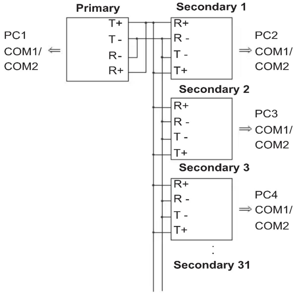
flowchart
graph TD
    A["PC1"] --> B["Primary"]
    C["COM1/ COM2"] <-- B
    B --> D["T+"]
    B --> E["T-"]
    B --> F["R-"]
    B --> G["R+"]
    D --> H["Secondary 1"]
    E --> H
    F --> I["Secondary 1"]
    G --> I
    H --> J["PC2"]
    H --> K["COM1/ COM2"]
    I --> L["Secondary 2"]
    L --> M["R+"]
    L --> N["R-"]
    L --> O["T-"]
    L --> P["T+"]
    M --> Q["PC3"]
    N --> R["COM1/ COM2"]
    O --> S["Secondary 3"]
    S --> T["R+"]
    S --> U["R-"]
    S --> V["T-"]
    S --> W["T+"]
    T --> X["PC4"]
    U --> X
    V --> X
    W --> X
    X --> Y["PC4"]
    X --> Z["COM1/ COM2"]
    style A fill:#f9f,stroke:#333
    style C fill:#f9f,stroke:#333
    style B fill:#ccf,stroke:#333
    style H fill:#ccf,stroke:#333
    style L fill:#ccf,stroke:#333
    style S fill:#ccf,stroke:#333
    style X fill:#ccf,stroke:#333
- For all IC-485AI units, set the unit to DCE or DTE depending on what type of device the IC-485AI will plug into (if it will plug into a DCE device, configure it for DTE, and vice versa).
- For all of the units set SW7 and SW8 according to the table on p.9 to configure each unit's RS-485 operating mode (see p.10 for RS-485 operation details).
Note: No more than 31 Secondary units can be connected.
Simplex
A Simplex configuration is one in which more than two devices are linked for communication using several IC-485AI units in a manner similar to Multidrop. The difference is that in a Simplex configuration, the Primary device can only talk, and the Secondary devices can only listen.
- Simplex uses reverse two wire cabling to link all the connected IC-485AI units, as shown in the figure below:
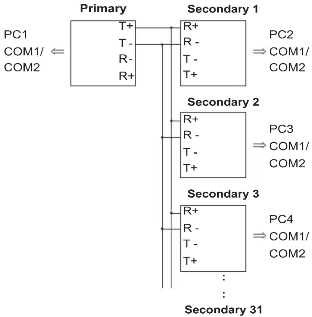
flowchart
graph TD
    A["PC1"] --> B["Primary"]
    C["COM1/COM2"] <--_D["T+"]
    D --> E["R+"]
    E --> F["Secondary 1"]
    G["T-"] --> H["R-"]
    I["R-"] --> J["T-"]
    K["R+"] --> L["T+"]
    M["PC2"] --> N["⇒ COM1/COM2"]
    O["Secondary 2"] --> P["R+"]
    Q["PC3"] --> R["R-"]
    S["⇒ COM1/COM2"]
    T["T-"] --> U["T+"]
    V["T+"] --> W["Secondary 3"]
    X["R+"] --> Y["R-"]
    Z["T-"] --> AA["T+"]
    AB["PC4"] --> AC["⇒ COM1/COM2"]
    AD["Secondary 31"] -.-> AE["..."]
- For all IC-485AI units, set the unit to DCE or DTE depending on what type of device the IC-485AI will plug into (if it will plug into a DCE device, configure it for DTE, and vice versa).
- For all of the units (Primary and Secondary), set SW7 ON; set SW8 ON.
Note: No more than 31 Secondary units can be connected.
- Make sure that all the devices you will be connecting up are powered off.
- Set each IC-485AI's configuration switches according to the information provided in the Switch Configuration and Operating Modes sections.
- Plug the IC-485AI's DB-25 female connector into the computer's RS-232C port.
- Connect the IC-485Al units to each other.
a) Use two or four wire twisted pair cable in a reverse or straight through configuration according to the information provided in the Switch Configuration and Operating Modes sections.
Note: 1. When tightening the terminal connector screws it is recommended to use a Phillips PH1 Screwdriver.
2. Over-tightening the terminal connector screws may result in damage to your IC-485AI and difficulty loosening the screws.
b) See p.17 for the Terminal Block pin assignments.
- Power on the computers. The units are now ready for operation.
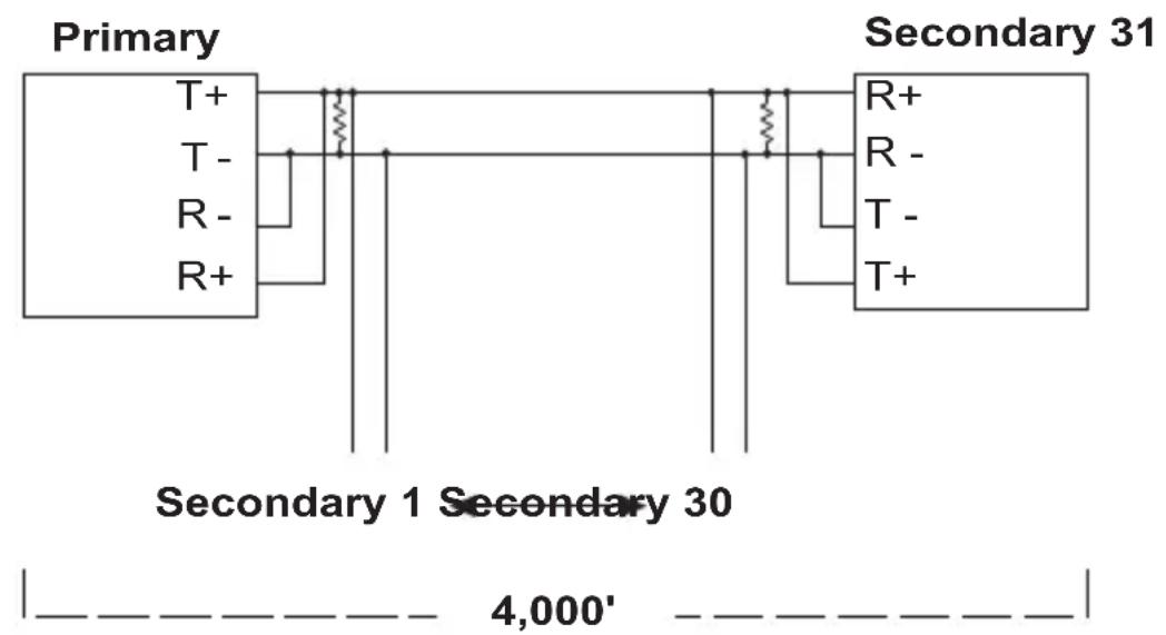
Note: When connecting units over long distances, it may be necessary to install 120Ω resistors. See the diagrams on the next page for details.
RS-422 / RS-485 Installation Diagrams
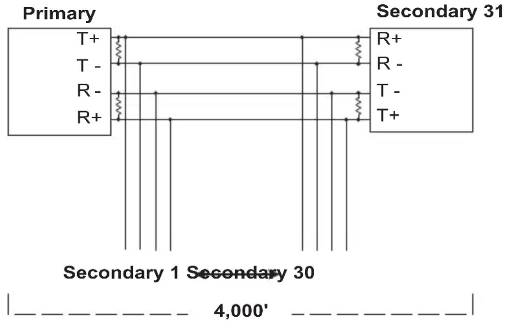
flowchart
graph TD
    A["Primary"] --> B["T+"]
    A --> C["T-"]
    A --> D["R-"]
    A --> E["R+"]
    F["Secondary 31"] --> G["R+"]
    F --> H["R-"]
    F --> I["T-"]
    F --> J["T+"]
    B --> K["4,000'"]
    C --> K
    D --> K
    E --> K
    G --> K
    H --> K
    I --> K
    J --> K
    style A fill:#f9f,stroke:#333
    style F fill:#ccf,stroke:#333
    style B fill:#fff,stroke:#333
    style C fill:#fff,stroke:#333
    style D fill:#fff,stroke:#333
    style E fill:#fff,stroke:#333
    style G fill:#fff,stroke:#333
    style H fill:#fff,stroke:#333
    style I fill:#fff,stroke:#333
    style J fill:#fff,stroke:#333
RS-422 Full Duplex
Note: When the distance between both ends of the installation is large and/or the transmitted signals are unstable, insert 120Ω terminal resistors between pins 1 and 2 and between pins 3 and 4 on the terminal blocks of the two units at each end of the installation.
RS-485 Half Duplex
Note: When the distance between both ends of the installation is large and/or the transmitted signals aren't stable, insert a 120Ω terminal resistor between pins 1 and 2 on the terminal blocks of the two units at each end of the installation.
Terminal Block Pin Assignments
| Pin DCE/DTE | ||
| 1 Transmit +V | ||
| 2 Transmit -V | ||
| 3 Receive -V | ||
| 4 | R | e |
C
Circuit Test
To test the IC-485AI's internal circuits, connect a dumb terminal to the unit and do the following:
- Set the DCE / DTE switch to the opposite of the terminal.
- Set all DIP Switch segments to ON.
- Connect one wire from Tx+ (1) to Rx+ (4); connect a second wire from Tx- (2) to Rx- (3).
- Set the terminal to Full Duplex.
- Set the baud rate of the communicaton application to 1200 bps.
- Enter data.
If the circuit is operational, data appears on the screen
RS-485 Operation Mode Flow Charts
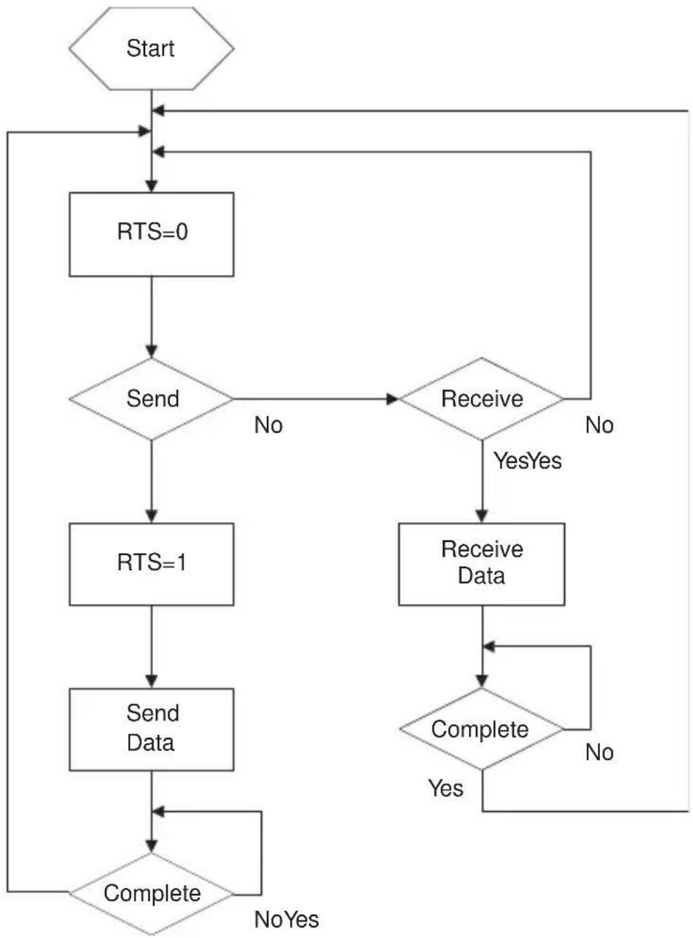
RTS Control Mode
flowchart
graph TD
    A["Start"] --> B["RTS=0"]
    B --> C{Send}
    C -->|No| D["Receive"]
    C -->|Yes| E["RTS=1"]
    E --> F["Send Data"]
    F --> G{Complete}
    G -->|No Yes| B
    G -->|Yes| H["Receive Data"]
    H --> I{Complete}
    I -->|No| B
    I -->|Yes| J["End"]
- The IC-485AI operates in RS-485 RTS Control Mode when both SW7 and SW8 are set to OFF.
- In this mode, RTS is pulled high when the computer makes a request to send data.
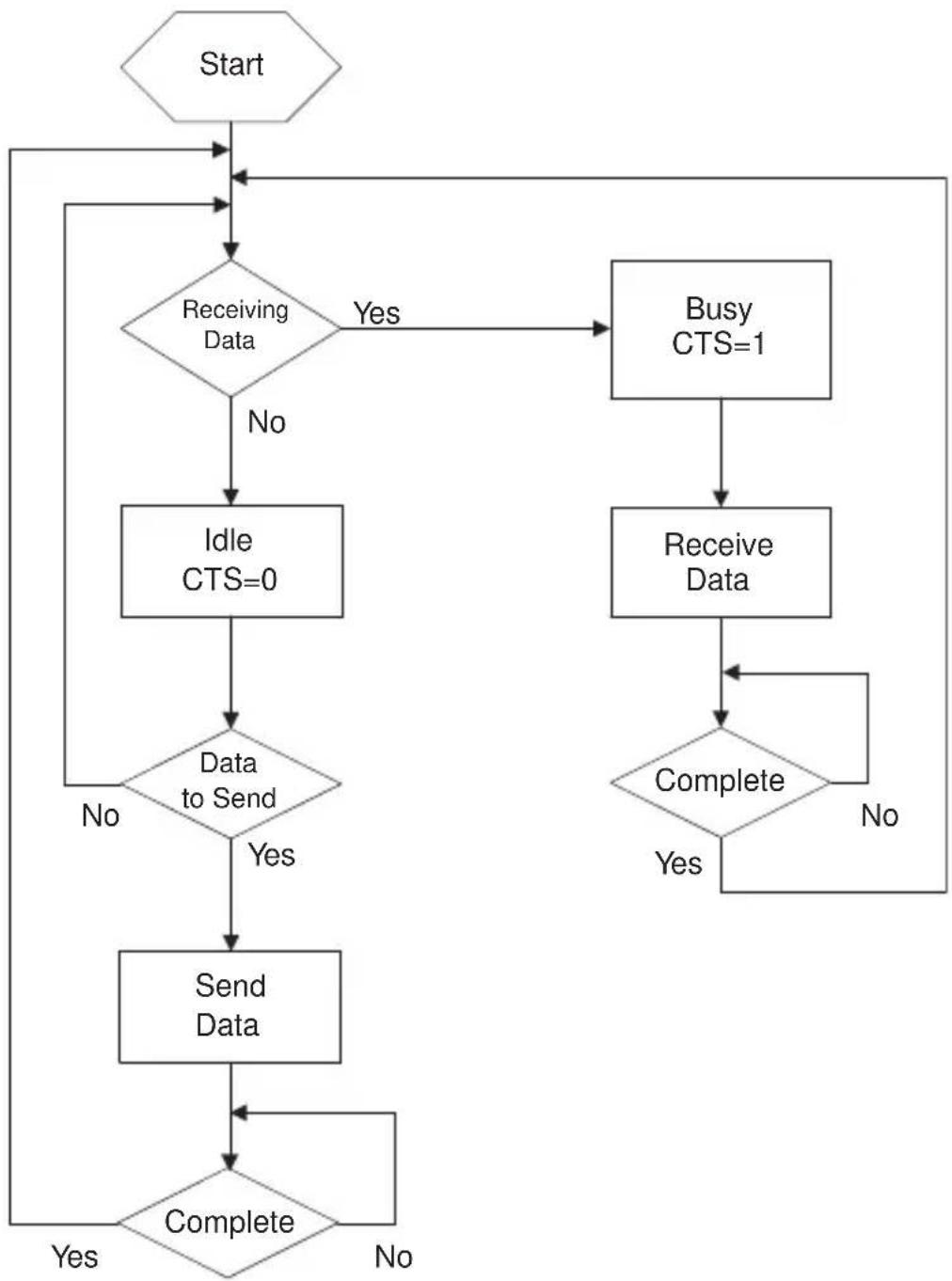
Auto Send Data Mode
flowchart
graph TD
    A["Start"] --> B{Receiving Data}
    B -->|No| C["Idle CTS=0"]
    B -->|Yes| D["Busy CTS=1"]
    C --> E{Data to Send}
    E -->|No| F["Send Data"]
    E -->|Yes| G["Complete"]
    D --> H["Receive Data"]
    H --> I{Complete}
    I -->|No| J["End"]
    I -->|Yes| K["End"]
    J --> L["End"]
    K --> M{Complete}
    L --> M
    M --> N["End"]
- The IC-485AI operates in RS-485 Auto Send Data Mode when SW7 is set to OFF, and SW8 is set to ON.
- In this mode, the status of the bus line is auto-detected in order to prevent more than one signal on the line.
If the bus line is busy, CTS is pulled high, and the IC-485AI will not send data to the bus line.
If the bus line is determined to be idle, CTS is pulled low and the IC-485AI sends data to the bus line.
DCE / DTE Connection Description
| Device's Connector Pin # | Cable | IC-485AI | ||||
| DCEDB-9 | DTEDB-9 | DCEDB-2 | DTEDB-25 | 25/25 or9/25 pin | DCEDB-25 | DTEDB-25 |
| □□□1 | 1 (PG) | 1 | 1 | Tx □ Rx | ||
| □2□3 | 3 2 | □□2 | 3 | |||
| □3□ | 2 □ | 2 □3 | □□3 □ | Rx □ Tx | ||
| □8□ | 7 □ | 5 □4 | □4 □ | 5RTS □ CTS | ||
| □7□ | 8 □ | 4 □5 | □5 □ | 4CTS □ RTS | ||
| □6□ | 6□ | 6□ | 6□ | (DSR) □ | 6□ | 6 |
| □5□ | 5□ | 7□ | 7□ | — SG □ | 7□ | 7 |
| □1□ | 1□ | 8 □8 | □(CD) □ | 8 □8 | ||
| □□□ | 9 □9 | □□9 □9 | 9 | |||
| □□□ | 10□ | 10□□ | 10□ | 10 | ||
| □□□ | 11□ | 11□□ | 11□ | 11 | ||
| □□□ | 12□ | 12□ | (SCD)_12□ | 12 | ||
| □□□ | 13□ | 13□ | (SCS) □ 13□ | 13 | ||
| □□□ | 14□ | 14□ | (STD) □ 14□ | 14 | ||
| □□□ | 15□ | 15□ | (TC) □ | 15□ | 15 | |
| □□□ | 16□ | 16□ | (SRD) □ 16□ | 16 | ||
| □□ | □ | 17□ | 17□ | (RC) □ | 17□ | 17 |
| □□□ | 18□ | 18□□ | 18□ | 18 | ||
| □□□ | 19□ | 19□ | (SRS) □ 19□ | 19 | ||
| □4□ | 4□ | 20□ | 20□ | (DTR) □ | 20□ | 20 |
| □□□ | 21□ | 21□ | (SQD) □ | 21□ 21 | ||
| □9□ | 9□ | 22□ | 22□ | (RI) □ | 22□ | 22 |
| □□□ | 23□ | 23□ | (DRS) □ 23□ | 23 | ||
| □□□ | 24□ | 24□ | (XTC) □ | 24□ | 24 | |
| □□□ | 25□ | 25□□ | 25□ | 25 | ||
Specifications
| Function Specification | 900mW (max.) | |
| Power Consumption DC 9V; | ||
| Data Rate Up to 115.2 Kbps | under 1200 m(4000 ft.) | |
| Connectors 1 x DB-25 female | (RS-232);1 x 4 Post Terminal Block (RS-422 / RS-485);1 x Grounding Tab | |
| Function Switches | Slide Switch | DCE / DTE Select |
| DIP Switch | Segment 1-3: Baud Rate;Segment 4: Reserved;Segment 5&6: Data Format (bits);Segment 7&8: RS-422 / RS-485Select | |
| Cable Distance Up to 1200 m (4000 ft.) | ||
| Operating Temperature 0 ~ 50°C | ||
| Storage Temperature | 20 ~ 60°C | |
| Humidity 0 ~ 80% RH | ||
| Housing Plastic (ABS) | ||
| Weight 60 g | ||
| Dimensions (L x W x H) 54 x | 74.5 x 18.5 mm | |
Troubleshooting
| Symptom Action | |
| Data Transmission Failure | Check that IC-485AI units are securely plugged into the computers' serial ports. |
| Check that the cables are properly set up and properly connected. | |
| Check that SW1 and the DIP Switch are set properly. | |
| Insert terminal resistors according to the information given on p. 13 | |
| Data Loss or Error Ch | Check that the Data Rate and Data Format are the same for all devices. |
| Insert terminal resistors according to the information given on p. 13 |
ATEN warrants its hardware in the country of purchase against flaws in materials and workmanship for a Warranty Period of two [2] years (warranty period may vary in certain regions/countries) commencing on the date of original purchase. This warranty period includes the LCD panel of ATEN LCD KVM switches. Select products are warranted for an additional year (see A+ Warranty for further details). Cables and accessories are not covered by the Standard Warranty.
What is covered by the Limited Hardware Warranty
ATEN will provide a repair service, without charge, during the Warranty Period. If a product is detective, ATEN will, at its discretion, have the option to (1) repair said product with new or repaired components, or (2) replace the entire product with an identical product or with a similar product which fulfills the same function as the defective product. Replaced products assume the warranty of the original product for the remaining period or a period of 90 days, whichever is longer. When the products or components are replaced, the replacing articles shall become customer property and the replaced articles shall become the property of ATEN.
To learn more about our warranty policies, please visit our website: http://www.aten.com/global/en/legal/policies/warranty-policy
- ♦ KCC Statement
- IC485AI User Manual
- Online Registration
- Online Support
- Package Contents
- Features
- Components
- Top view:
- Bottom View:
- DIP Switch
- ◆ SW 5-6: Data Format
- - SW 7-8: RS-422 / RS-485 Operating Mode
- Point-to-Point
- Point-to-Point 4 Wire Full Duplex
- Point-to-Point 2 Wire Half Duplex
- Multidrop
- Multidrop Full Duplex
- Multidrop Half Duplex
- Simplex
- Terminal Block Pin Assignments
- Circuit Test
- RS-485 Operation Mode Flow Charts
- RTS Control Mode
- Auto Send Data Mode
- DCE / DTE Connection Description
- What is covered by the Limited Hardware Warranty
Brand : ATEN
Model : IC485AI
Category : Audio/video converter