AOC-SASLP-H8IR - Controller Supermicro - Free user manual and instructions
Find the device manual for free AOC-SASLP-H8IR Supermicro in PDF.


| Product Type | SAS/SATA RAID Controller |
| Model | AOC-SASLP-H8IR |
| Brand | Supermicro |
| Form Factor | Low Profile MD2 |
| Interface | PCI Express x8 |
| Ports | 8 internal (SFF-8087 connectors) |
| Supported Drives | SAS and SATA (up to 3 Gbps per port) |
| RAID Levels | 0, 1, 10, 5, 6 |
| Controller Chip | LSI SAS1068E |
| Dimensions (L x H) | 16.8 cm x 6.9 cm |
| Weight | Approximately 100 g |
| Power Consumption | 8 W typical |
| Operating Temperature | 0°C to 55°C |
| Storage Temperature | -20°C to 80°C |
| Supported Operating Systems | Windows, Linux, VMware |
| Maintenance | Clean with a dry, lint-free cloth; avoid moisture and static discharge. |
| Safety | Handle by edges only; install in anti-static bag; power off system before installation. |
| Spare Parts and Repairability | No user-serviceable parts; contact Supermicro for RMA. |
| Compliance | RoHS, CE, FCC Class B |
Frequently Asked Questions - AOC-SASLP-H8IR Supermicro
User questions about AOC-SASLP-H8IR Supermicro
0 question about this device. Answer the ones you know or ask your own.
Ask a new question about this device
Download the instructions for your Controller in PDF format for free! Find your manual AOC-SASLP-H8IR - Supermicro and take your electronic device back in hand. On this page are published all the documents necessary for the use of your device. AOC-SASLP-H8IR by Supermicro.
USER MANUAL AOC-SASLP-H8IR Supermicro
The information in this User's Manual has been carefully reviewed and is believed to be accurate. The vendor assumes no responsibility for any inaccuracies that may be contained in this document, makes no commitment to update or to keep current the information in this manual, or to notify any person or organization of the updates. Please Note: For the most up-to-date version of this manual, please see our web site at www.supermicro.com.
Super Micro Computer, Inc. ("Supermicro") reserves the right to make changes to the product described in this manual at any time and without notice. This product, including software, if any, and documentation may not, in whole or in part, be copied, photocopied, reproduced, translated or reduced to any medium or machine without prior written consent.
IN NO EVENT WILL SUPERMICRO BE LIABLE FOR DIRECT, INDIRECT, SPECIAL, INCIDENTAL, SPECULATIVE OR CONSEQUENTIAL DAMAGES ARISING FROM THE USE OR INABILITY TO USE THIS PRODUCT OR DOCUMENTATION, EVEN IF ADVISED OF THE POSSIBILITY OF SUCH DAMAGES. IN PARTICULAR, SUPERMICRO SHALL NOT HAVE LIABILITY FOR ANY HARDWARE, SOFTWARE, OR DATA STORED OR USED WITH THE PRODUCT, INCLUDING THE COSTS OF REPAIRING, REPLACING, INTEGRATING, INSTALLING OR RECOVERING SUCH HARDWARE, SOFTWARE, OR DATA.
Any disputes arising between manufacturer and customer shall be governed by the laws of Santa Clara County in the State of California, USA. The State of California, County of Santa Clara shall be the exclusive venue for the resolution of any such disputes. Super Micro's total liability for all claims will not exceed the price paid for the hardware product.
FCC Statement: This equipment has been tested and found to comply with the limits for a Class A digital device pursuant to Part 15 of the FCC Rules. These limits are designed to provide reasonable protection against harmful interference when the equipment is operated in a commercial environment. This equipment generates, uses, and can radiate radio frequency energy and, if not installed and used in accordance with the manufacturer's instruction manual, may cause harmful interference with radio communications. Operation of this equipment in a residential area is likely to cause harmful interference, in which case you will be required to correct the interference at your own expense.
California Best Management Practices Regulations for Perchlorate Materials: This Perchlorate warning applies only to products containing CR (Manganese Dioxide) Lithium coin cells. "Perchlorate Material-special handling may apply. See www.dtsc.ca.gov/hazardouswaste/perchlorate"
WARNING: Handling of lead solder materials used in this product may expose you to lead, a chemical known to the State of California to cause birth defects and other reproductive harm.
Manual Revision 1.0
Release Date: December 2, 2008
Unless you request and receive written permission from Super Micro Computer, Inc., you may not copy any part of this document.
Information in this document is subject to change without notice. Other products and companies referred to herein are trademarks or registered trademarks of their respective companies or mark holders.
Copyright © 2008 by Super Micro Computer, Inc.
All rights reserved.
Printed in the United States of America
Table of Contents
Introduction
Overview ......v
Product Features ......v
Operating Systems Supported ....v
Manual Images ....v
Contacting Supermicro ......vi
Returning Merchandise for Service....vii
Chapter 1 Safety Guidelines
1-1 ESD Safety Guidelines 1-1
1-2 General Safety Guidelines 1-1
1-3 An Important Note to Users 1-2
Chapter 2 Connectors and LED Indicators
2-1 Front Connectors and Jumpers 2-1
Front Connectors 2-1
2-2 Front Connector and Pin Definitions.... 2-2
2-3 LED Functions 2-3
RAID Minimum Drive Requirements 2-4
Chapter 3 WebBIOS Configuration
3-1 Introduction....3-1
3-2 Accessing the WebBIOS 3-1
3-3 WebBIOS Configuration Wizard.... 3-1
WebBIOS Configuration Wizard - Auto Configuration 3-2
WebBIOS Configuration Wizard - Custom Configuration 3-2
3-4 Device Properties 3-3
Chapter 4 MegaRAID Storage Manager Software Overview and Installation
4-1 Overview 4-1
Creating Storage Configurations.... 4-1
Maintaining Storage Configurations 4-2
4-2 Hardware and Software Requirements 4-2
4-3 Installation 4-3
Installing MegaRAID Storage Manager Software for Linux 4-6
Linux Error Messages 4-7
Chapter 5 MegaRAID Storage ManagerWindow and Menus
5-1 Starting MegaRAID Storage Manager Software 5-1
5-2 MegaRAID Storage Manager Window 5-4
Physical/Logical View Panel 5-4
Event Log Panel 5-6
Menu Bar 5-6
File Menu 5-6
Operations Menu 5-6
Group Operations Menu 5-7
Log Menu 5-7
Help Menu 5-7
Chapter 6 Configuration
6-1 Creating a New Storage Configuration....6-1
Using Manual Configuration: RAID 50....6-14
6-2 Adding Hotspare Disks 6-15
6-3 Changing Adjustable Task Rates 6-16
6-4 Changing Virtual Disk Properties 6-17
6-5 Deleting a Virtual Disk.... 6-17
6-6 Saving a Storage Configuration to Disk....6-18
6-7 Clearing a Storage Configuration from a Controller 6-18
6-8 Adding a Saved Storage Configuration 6-19
Introduction
Overview
This manual is written for system integrators, PC technicians and knowledgeable PC users who intend to integrate SuperMicro's USASLP-H8iR Add on Card to their system.
Product Features
The AOC-USAS-H8ir offers the following features:
UIO Form Factor.
Two Internal "ipass" cable ports.
Support for RAID 0, 1, 5, 6, 10, 50, and 60.
Operating Systems Supported
The AOC-USAS-H8ir support the following Operating Systems (OS):
Windows 2000/Windows XP/Windows 2003 •
Red Hat Enterprise Linux/SUSE Linux •
Each operating system must include the latest patches, hot fixes, and at least, 256 MB of free hard drive space.
Manual Images
All images and layouts shown in this user's guide are based upon the latest PCB Revision available at the time of publishing. The card you have received may or may not look exactly the same as the graphics shown in this manual.
Contacting Supermicro
Headquarters
Address: Super Micro Computer, Inc.
980 Rock Ave.
San Jose, CA 95131 U.S.A.
Tel: +1 (408) 503-8000
Fax: +1 (408) 503-8008
Email: marketing@supermicro.com (General Information)
support@supermicro.com (Technical Support)
Web Site: www.supermicro.com
Europe
Address: Super Micro Computer B.V.
's-Hertogenbosch, The Netherlands
Tel: +31 (0) 73-6400390
Fax: +31 (0) 73-6416525
Email: sales@supermicro.nl (General Information)
support@supermicro.nl (Technical Support)
rma@supermicro.nl (Customer Support)
Asia-Pacific
Address: Super Micro Computer, Inc.
4F, No. 232-1, Liancheng Rd.
Chung-Ho 235, Taipei County
Taiwan, R.O.C.
Tel: +886-(2) 8226-3990
Fax: +886-(2) 8226-3991
Web Site: www.supermicro.com.tw
Technical Support:
Email: support@supermicro.com.tw
Tel: 886-2-8226-1900
Returning Merchandise for Service
A receipt or copy of your invoice marked with the date of purchase is required before any warranty service will be rendered. You can obtain service by calling your vendor for a Returned Merchandise Authorization (RMA) number. When returning to the manufacturer, the RMA number should be prominently displayed on the outside of the shipping carton, and mailed prepaid or hand-carried. Shipping and handling charges will be applied for all orders that must be mailed when service is complete.
For faster service, RMA authorizations may be requested online (http://www.supermicro.com/support/rma/).
Whenever possible, repack the backplane in the original Supermicro box, using the original packaging materials. If these are no longer available, be sure to pack the backplane in an anti-static bag and inside the box. Make sure that there is enough packaging material surrounding the backplane so that it does not become damaged during shipping.
This warranty only covers normal consumer use and does not cover damages incurred in shipping or from failure due to the alteration, misuse, abuse or improper maintenance of products.
During the warranty period, contact your distributor first for any product problems.
Notes
Chapter 1
Safety Guidelines
To avoid personal injury and property damage, carefully follow all the safety steps listed below when accessing your system or handling the components.
1-1 ESD Safety Guidelines
Electrostatic Discharge (ESD) can damage electronic components. To prevent damage to your system, it is important to handle it very carefully. The following measures are generally sufficient to protect your equipment from ESD.
Use a grounded wrist strap designed to prevent static discharge.
Touch a grounded metal object before removing a component from the antistatic bag.
- Handle the add-on card by its edges only; do not touch its components, peripheral chips, memory modules or gold contacts.
When handling chips or modules, avoid touching their pins.
Put the card and peripherals back into their antistatic bags when not in use.
1-2 General Safety Guidelines
Always disconnect power cables before installing or removing any components • from the computer.
Disconnect the power cable before installing or removing any cables from the system.
- Make sure that the add-on card is securely and properly installed on the motherboard to prevent damage to the system due to power shortage.
1-3 An Important Note to Users
All images and layouts shown in this user's guide are based upon the latest PCB • revision available at the time of publishing. The card you have received may or may not look exactly the same as the graphics shown in this manual.
Chapter 2
Connectors and LED Indicators
2-1 Front Connectors and Jumpers
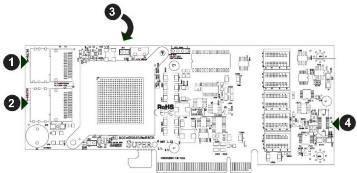
Figure 2-1: Front Connectors
Front Connectors
Front SAS Connectors
Internal SAS connector1.
Internal SAS connector2.
I-button (Not shown - located on the back of the add-on card)3.
Board-to-board connector4.
2-2 Front Connector and Pin Definitions
1. Internal SAS Connector (Drive 0-3)
The Internal SAS port connects to the back-plane allowing the motherboard to access the hard drives. This connector supports up to four HDD ports. This card supports SAS, SATA1, and SATA2 drives.
Use a single port SAS "ipass" cable (Super Micro order number CBL - 0108L-02).
2. Internal SAS Connector (Drive 4-7)
The Internal SAS port connects to the back-plane allowing the motherboard to access the hard drives. This connector supports up to four HDD ports. This card supports SAS, SATA1, and SATA2 drives.
Use a single port SAS "ipass" cable (Super Micro order number CBL - 0108L-02).
3. I-Button
The I-Button is located on the back side of the SAS- allows RAID operation with MegaRAID firmware.
4. Board-to-Board Connector
This 20-pin connector interfaces with the Battery Backup Unit (BBU). The .BBU is an optional accessory and is not included with this card.
2-3 LED Functions
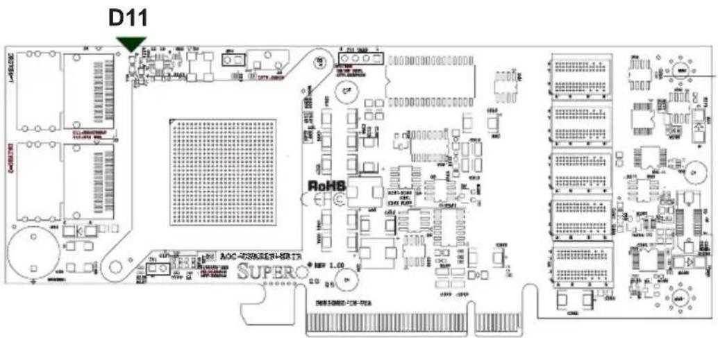
Figure 2-2: Front LED Location
The LED indicated as D11 functions as both the add-on card's heartbeat LED and an overheat indicator. See the table below for information on the status indicated by this LED.
| LED Functions | ||
| LED Normal State Specifications | ||
| Heartbeat LED (D11) On Blinks during normal operation | ||
| Overheat LED (D11) Off | Solid red when the 1078 chip is overheated | |
RAID Minimum Drive Requirements
Use the following chart to determine the minimum number of hard drives needed to set up a RAID environment.
| RAID Minimum Hard Drives | |
| RAID 0 2 | |
| RAID 1 2 | |
| RAID 5 3 | |
| RAID 6 4 | |
| RAID 10 4 (2 RAID 1 array) | |
| RAID 50 6 (2 RAID 5 arrays) | |
| RAID 60 6 (2 RAID 6 arrays) | |
Chapter 3
WebBIOS Configuration
3-1 Introduction
The WebBIOS configuration manages RAID configurations on SAS controllers. The utility works independently of the operating system.
3-2 Accessing the WebBIOS
To Start the WebBIOS Configuration:
When prompted during bootup, press 1. CTRL + H.
In the 2. Adapter Selection screen, select an adapter.
Click 3. Start.
3-3 WebBIOS Configuration Wizard
The Configuration Wizard is used to setup RAID arrays and virtuals in section includes an overview of use. For more indepth information and descriptions, see the WebBIOS Help and other LSI documentation.
Starting the Configuration Wizard
- Click the Configuration Wizard link located on the left hand side on the main screen.
- Select a configuration option: Clear Configuration, New Configuration, or Add Configuration. Note: Clear Configuration and New Configuration settings will delete existing data. Create a backup before choosing an option.
Click 3. Next.
- Select Custom Configuration, Auto Configuration with Redundancy, or Auto Configuration without Redundancy and click Next.
WebBIOS Configuration Wizard - Auto Configuration
When using either Auto Configuration setting, do the following:
When prompted to review the new configuration, review the settings.1.
- Click Accept or Back to change any settings. (Auto Configuration with Redundancy creates a RAID 5 configuration if at least three disks are available. If only two disks are available, the setup creates RAID 1.)
Click Yes to save the configuration, and Yes again to initialize the new virtual 3. disk.
WebBIOS CU will begin the initialization of the virtual drives.
WebBIOS Configuration Wizard - Custom Configuration
This section gives an overview of the WebBIOS Custom Configuraiton. When using the Custom Configuration setting, consult the WebBIOS disk Help file and other LSI documentation for more complete instructions.
WebBIOS Configuration
The Custom Configuration window includes two sections: Physical Drives 1. and Disk Groups. Press CTRL and select each ready desired physical drives from the group. Select two drives for RAID 1 and three drives for RAID 5.
Click Accept DG.2.
For other RAID levels, repeat steps 1 and 2 and do the following: for RAID 10 3. configuration, create a second RAID 1 disk group. For RAID 50 confirmation, select physical drives for a second RAID 5 disk group.
- Click Next when you have completed selecting drives for disk groups.
The span definition screen appears. Select one of the available disk groups and click Add to Span and click Next.
In the Virtual Disk Definition screen, set the following: 5.
RAID Level: To create a RAID 10 (spanned), add both disk groups you created earlier to SPAN. Then click Next and select the RAID level on the virtual disk definition. Do the same for RAID 50 and RAID 60.
Stripe Size
Access Policy: Select Read/Write, Read Only, or Blocked.
Read Policy: Use Ahead, Normal, or Adaptive.
Write Policy: Use WBack, WThru, or Bad BBU
IO Policy: Use this setting to read to a specific virtual disk. Cached mode reads to buffered in cached memory and in Direct mode reads are not buffered.
Disk Cache Policy: Enable, Disable, and Unchanged.
Disable BGI: Selecting Yes disables background initiation.
Select Size: Select the size for the virtual disk.
Click Accept or Reset.6.
Click Next.7.
- Preview the configuration and click Accept to continue or Back to go to the previous screen, and then click Yes to continue
3-4 Device Properties
This section gives an overview for the properties of the adapters, virtual disks, and drives.
Adapter Properties
Click the Adapter Properties to see the definitions for each adapter. There are two screens. The first screen is read-only. Click Next to see the second screen, which settings can be adjusted. For more information on these settings, see the application Help or LSI documentation.
Virtual Disk Properties
This section gives an overview of the virtual disk properties accessed in the Web-BIOS Main screen.
The Properties panel shows the virtual disk RAID level and other defining information. Before changes settings, you should make a backup of the information. You can change the settings by doing any of the following:
Locate: Sets the designated LEDs on the physical drives of the virtual disk (requires SAFTE support).
Fast or Slow: Select either to initialize the virtual drives.
CC: runs a consistency check (not available for RAID 0).
Physical Drive Properties
This section gives an overview of the physical drive properties accessed in the WebBIOS Main screen.
The physical drive properties cannot be changed at this screen. The following information can be changed:
Select MakeDriveOffline to push the drive offline.
Select Locate to enable to drive LEDs. The drive must be in the enclosure.
Prepare for removal option may be available.
Battery Backup Unit
If the card has a battery backup, do the following to view the battery information.
- Click Adapter Properties in the WebBIOS main screen.
- Click Next.
- Click the word Present in the Battery Backup field.
System Event Information
This section gives an overview of the System Event properties.
Do the following to view event information:
Click Events in the WebBIOS main screen.1.
Choose an Event Locale from the menu.2.
Select an Event Class of Information, Warning, Critical, Fatal, or Dead and 3. choose the number of events to view, and then click Go.
Notes
Chapter 4
MegaRAID Storage Manager Software Overview and Installation
MegaRAID Storage Manager software is a configuration and monitoring utility used with the Embedded MegaRAID software. This chapter provides a brief overview of the MegaRAID Storage Manager software and explains how to install it on the supported operating systems.
4-1 Overview
MegaRAID Storage Manager software enables you to configure, monitor, maintain storage configurations created under Embedded MegaRAID software. The MegaRAID Storage Manager graphical user interface (GUI) makes it easy for you to create and manage storage configurations.
Note: MegaRAID Storage Manager software can be used to manage a wide range of MegaRAID controllers. Some MegaRAID Storage Manager software features are not applicable for Embedded MegaRAID software.
Creating Storage Configurations
MegaRAID Storage Manager software enables you to easily configure the controllers, disk drives, and virtual disks on your workstation or server. The Configuration Wizard greatly simplifies the process of creating arrays and virtual disks.
You can use the Configuration Wizard Auto Configuration mode to automate create the best possible configuration with the available hardware. You can the Guided Configuration mode, which asks you a few brief questions about configuration, and then creates it for you. Or you can use the Manual Configuration mode, which gives you complete control over all aspects of the storage configurationMonitoring Storage Devices
MegaRAID Storage Manager software displays the status of virtual disks, physical disks, and other storage devices on the workstation or server that you are monitoring. System errors and events are recorded in an event log file and are displayed on the screen. Special device icons appear on the screen to notify you of disk failures and other events that require immediate attention.
Maintaining Storage Configurations
You can use MegaRAID Storage Manager software to perform system maintenance tasks such as running consistency checks on arrays that support redundancy.
4-2 Hardware and Software Requirements
The hardware requirements for MegaRAID Storage Manager software are as follows:
PC-compatible computer with an IA-32 (32-bit) Intel Architecture processor or an EM64T (64-bit) processor and at least 128 Mbytes of system memory (256 Mbytes recommended)
Hard disk drive with at least 50 Mbytes available free space •
The supported operating systems for the MegaRAID Storage Manager software are as follows:
- Microsoft Windows 2000, Microsoft Windows Server 2003, and Microsoft Windows XP.
Red Hat Linux 3.0 or 4.0 •
SUSE SLES 9, with latest updates and service packs •
Refer to your server documentation and to the operating system documentation for more information on hardware and operating system requirements..
4-3 Installation
This section explains how to install (or reinstall) MegaRAID Storage Manager software on your workstation or server for the supported operating systems: Microsoft Windows, Red Hat Linux, and SUSE Linux. 5.3.1 Installing MegaRAID Storage Manager Software on Microsoft Windows
Follow these steps if you need to install MegaRAID Storage Manager software on a system running Microsoft Windows 2000, Microsoft Windows Server 2003, or Microsoft Windows XP:
Installation
Insert the MegaRAID Storage Manager software installation CD in the CD-1. ROM drive. If necessary, find and double-click the setup.exe file to start the installation program.
- When the Welcome screen appears, click Next. If MegaRAID Storage Manager software is already installed on this system, the Program Maintenance screen appears. Read the screen text and select Modify, Repair, or Remove.
When the next screen appears, read and accept the user license, and click 3. Next. The Customer Information screen appears.
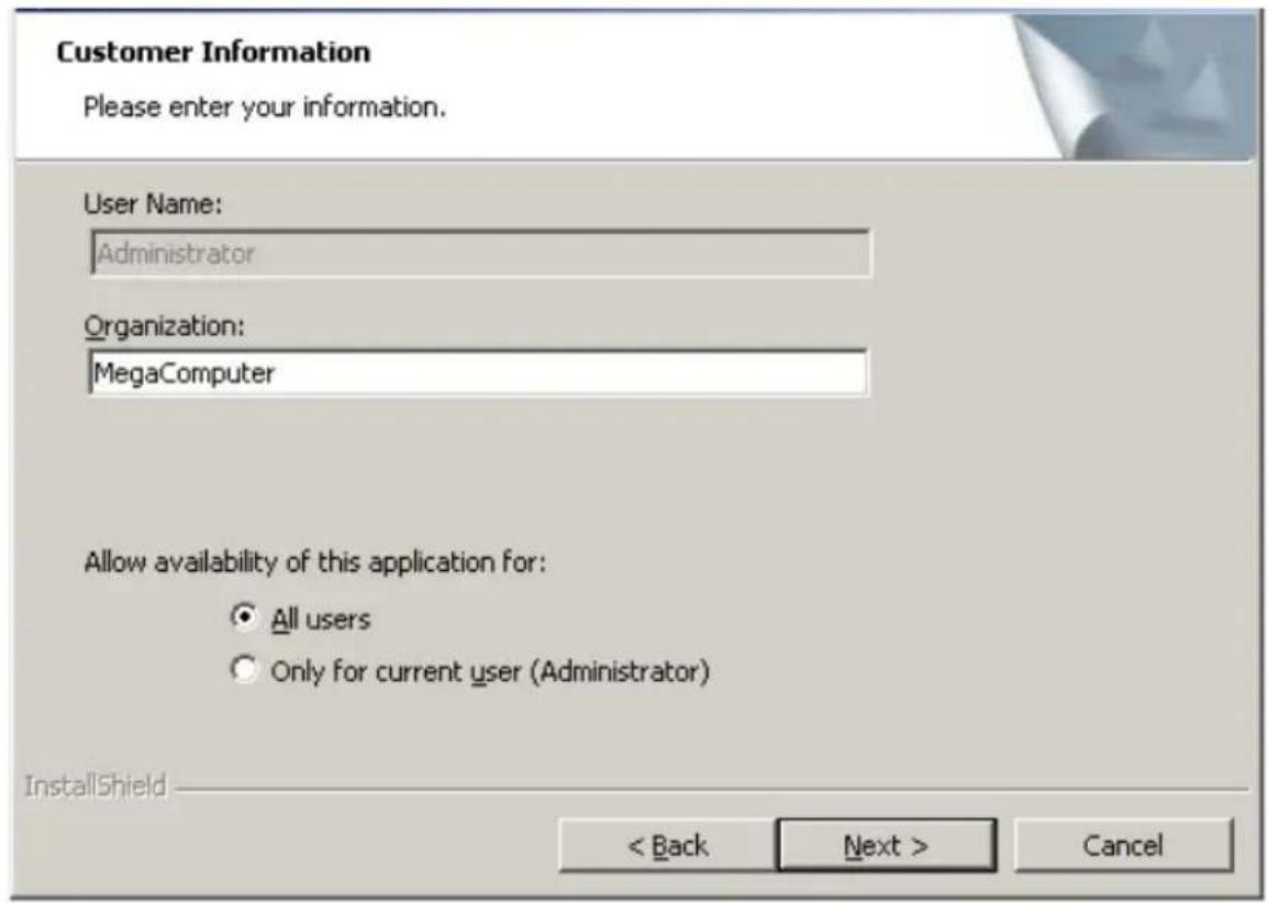
Figure 4-1: Customer Information Screen
Enter your user name and organization name. In the bottom part of the 4. screen, select an installation option:
- If you select All users, any user with administrative privileges can use this version of MegaRAID Storage Manager software to view or change storage configurations.
- If you select Only for current user (Administrator), the MegaRAID Storage Manager shortcuts and associated icons will be available only to the user with this user name.
Click 5. Next to continue.
- On the next screen, accept the default Destination Folder, or click Change to select a different destination folder. Click Next to continue.
The Setup Type screen appears.
Select one of the Setup options. The options are fully explained in the screen 7. text.
Normally, you would select Complete if you are installing MegaRAID Storage Manager software on a server.
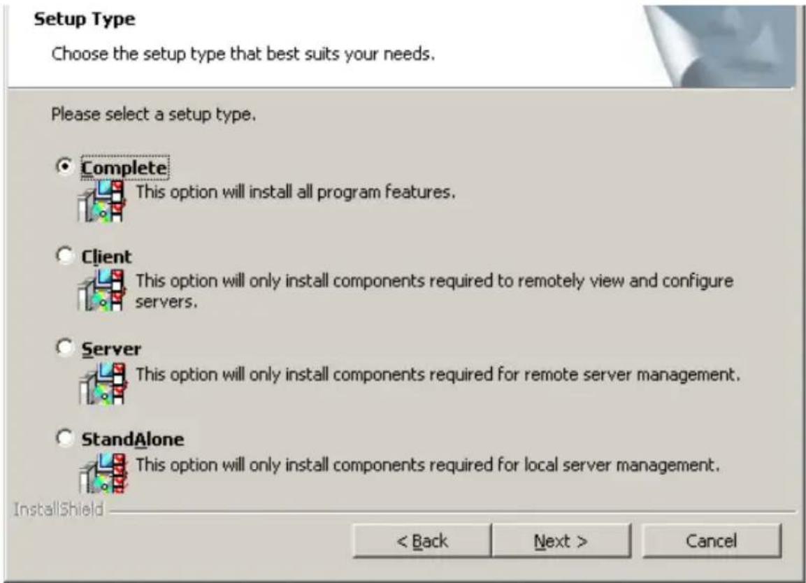
Figure 4-2: Setup Type Screen
Select Client if you are installing MegaRAID Storage Manager software on a PC that will be used to view and configure servers over a network.
Select Server to install only those components required for remote server management
Select StandAlone if you will use MegaRAID Storage Manager software to create and manage storage configurations on a standalone workstation.
Click Next to proceed.8.
Click Install to install the program.9.
Click Finish when the final Configuration Wizard screen appears.10.
If you select Client installation for a PC used to monitor servers, and if there are no available servers with a registered framework on the local subnet (that is, servers with a complete installation of MegaRAID Storage Manager software), you cannot
connect to a remote server unless you first edit the startupui.bat file. Specifically, you must add the IP address of the remote server to the end of the startupui.bat file.
For example, to connect to a remote framework on server 192.168.0.10, add the IP address to the end of startupui.bat as shown in this example: start JRE\bin\javaw-classpath.;GUI.jar GUI.VivaldiStartupDialog ajsgyqkj=71244 192.168.0.10
Be sure to include a space in front of the IP address, as shown in the example.
Installing MegaRAID Storage Manager Software for Linux
Follow these steps if you need to install MegaRAID Storage Manager software on a system running Red Hat Linux or SUSE Linux:
Installing MegaRAID Storage Manager
Copy the SSM_linux_installer...tar.gz file to a temporary folder.1.
- Untar the SSM_linux_installer...tar.gz file using the following command: tar -zxvf SSM_linux_installer...tar.gz A new disk directory is created.
Go to the new disk directory.3.
In the disk directory, find and read the readme.txt file.4.
To start the installation, enter the following command: 5. ./install.sh
If you select Client installation for a PC used to monitor servers, and if there are no available servers with a registered framework on the local subnet (that is, servers with a complete installation of MegaRAID Storage Manager software), you cannot connect to a remote server unless you first edit the startupui.sh file. Specifically, you must add the IP address of the remote server to the end of the startupui.sh file.
For example, to connect to a remote framework on server 192.168.0.10, add the IP address to startupui.sh as shown in this example:
Start JRE\bin\javaw -classpath .;GUI.jar GUI.VivaldiStartupDialog ajsgyqkj=71244 192.168.0.10
Be sure to include a space in front of the IP address, as shown in the example.
Linux Error Messages
One or more of the following messages may appear while you are installing Mega-RAID Storage Manager software on a Linux system:
- More than one copy of MegaRAID Storage Manager software has been installed.
This message indicates that the user has installed more than one copy of MegaRAID Storage Manager software. (This can be done by using the rpm-force command to install the rpm file directly, which is not recommended, instead of using the install.sh file.) In such cases, the user must uninstall all the rpm files manually before installing MegaRAID Storage Manager software with the procedure listed previously.
The version is already installed.
This message indicates that the version of MegaRAID Storage Manager software you are trying to install is already installed on the system.
The installed version is newer.
This message indicates that a version of MegaRAID Storage Manager software is already installed on the system, and it is a newer version than the version you are trying to install.
Exiting installation.
This is the message that appears when the installation is complete.
RPM installation failed.
This message indicates that the installation failed for some reason.
Additional message text explains the cause of the failure.
Notes
Chapter 5
MegaRAID Storage Manager Window and Menus
This chapter explains how to start MegaRAID Storage Manager software and describes the MegaRAID Storage Manager window and menus.
5-1 Starting MegaRAID Storage Manager Software
Follow these steps to start MegaRAID Storage Manager software and view the main window:
Starting MegaRAID Storage Manager
- Start the program using the method required for your operating system environment:
To start MegaRAID Storage Manager software on a Microsoft Windows system, select Start, Programs, MegaRAID Storage Manager, StartupUI, or double-click the MegaRAID Storage Manager shortcut on the desktop.
Note: If a warning appears stating that Windows Firewall has blocked some features of the program, click Unblock to allow MegaRAID Storage Manager software to start. (The Windows Firewall sometimes blocks the operation of programs that use Java.)
To start MegaRAID Storage Manager software on a Red Hat Linux system, • select Applications, System Tools, MegaRAID Storage Manager StartupUI.
To start MegaRAID Storage Manager software on a SUSE SLES 9 system, • select Start, System, More Programs, MegaRAID Storage Manager.
When the program starts, the Select Server window appears.
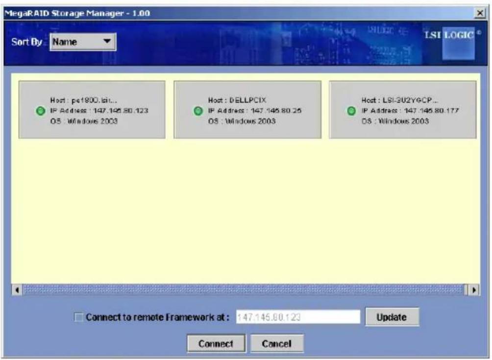
Figure 5-1: Select Server Window
If the circle in the server icon is yellow instead of green, it means that the server is running in a degraded state—for example, because a disk drive used in a virtual disk has failed. If the circle is red, the storage configuration in the server has failed.
Note: To access servers on a different subnet, type in the box at the bottom of the screen the IP address of a server in the desired subnet where MegaRAID Storage Manager software is running, and click Update. If you check the Connect to remote Framework box, you can also access a standalone installation of MegaRAID Storage Manager software, if it has a network connection.
- Double-click the icon of the server that you want to access. The Server Login window appears.
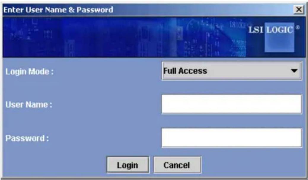
Figure 5-2: User Name/Password Window
- Select an access mode from the drop-down menu.
Select Full Access if you need to both view the current configuration and change the configuration.
SelectViewOnlyifyouneedtoonlyviewandmonitortheconfiguration.
- Enter your user name and password, and click Login.
Note: If the computer is networked, this is the login to the computer itself, not the network login.
You must enter the root/administrator user name and password to use Full Access mode. If your user name and password are correct for the Login mode you have chosen, the main MegaRAID Storage Manager window appears.
5-2 MegaRAID Storage Manager Window
This section describes the MegaRAID Storage Manager window.
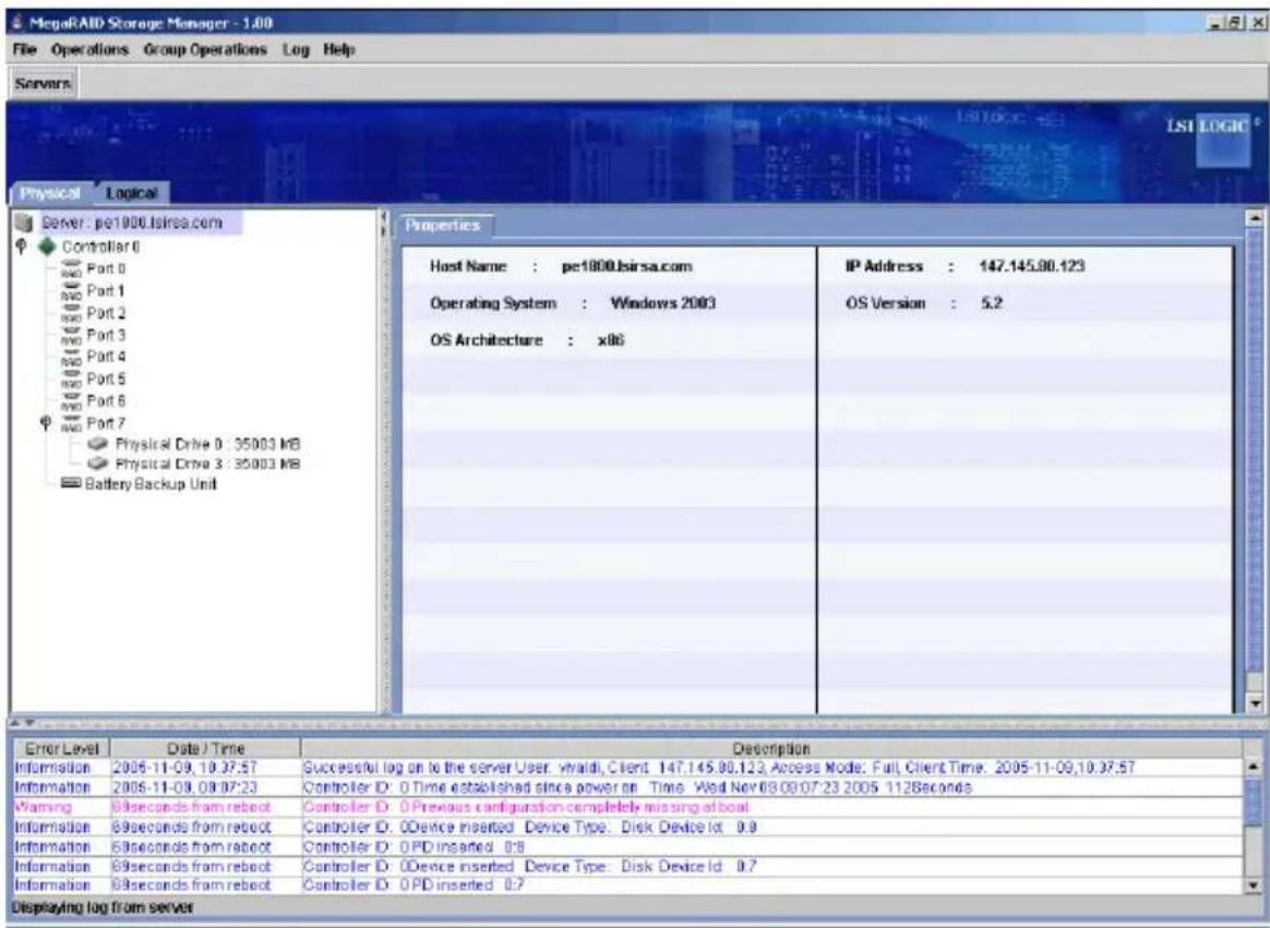
Figure 5-3: Storage Manager Window
The following topics describe the panels and menu options that appear in this window.
Physical/Logical View Panel
The left panel of the MegaRAID Storage Manager window displays either the Physical view or the Logical view of the system and the devices in it, depending on which tab is selected.
The Physical view shows the hierarchy of physical devices in the system. At the top of the hierarchy is the system itself. One or more controllers are installed in the system. Each controller has one or more ports. Disk drives and other devices are attached to the ports.
- The Logical view shows the hierarchy of controllers, virtual disks, and disk groups that are defined on the system. (Physical drives also appear in the Logical view, so you can see which physical drives are used by each virtual disk.)
The following icons in the left panel represent the controllers, disk drives, and other devices:
System •
Controller •
Port •
Array •
Virtual disk •
Physical drive •
A red circle to the right of an icon indicates that the device has failed.
A yellow circle to the right of an icon indicates that a device is running in a degraded state. Properties/Operations/Graphical View Panel
The right panel of the MegaRAID Storage Manager window has either two or three tabs, depending on what kind of device is selected in the left panel.
The Properties tab displays information about the selected device. For example, if a controller icon is selected in the left panel, the Properties tab lists information such as the controller name and the device port count.
The Operations tab lists the operations that can be performed on the device that is selected in the left panel. Some types of devices, such as arrays and ports, do not have operations associated with them.
- The Graphical View tab can be selected in the right panel if a physical drive or virtual disk is selected in the left panel. In graphical view, the device's storage capacity is color coded according to the legend shown on the screen. For example, on a physical drive configured space is blue, available space is white, and reserved space is red.
Event Log Panel
The lower part of the MegaRAID Storage Manager window displays the system event log entries. New event log entries appear during the session. Each entry has a timestamp and date, an error level indicating the severity of the event, and a brief description of the event.
Menu Bar
Here are brief descriptions of the main selections on the MegaRAID Storage Manager menu bar.
File Menu
The File menu has an Exit option for exiting from the MegaRAID Storage Manager software. It also has a Rescan option for updating the display in the MegaRAID Storage Manager window. (Rescan is seldom required; the display normally updates automatically.)
Operations Menu
The Operations menu is available when a controller, physical drive, or logical drive is selected in the MegaRAID Storage Manager window. The Operations menu options vary depending on what type of device is selected in the left panel of the MegaRAID Storage Manager window. The options also vary depending on the current state of the selected device. For example, if you select an offline physical drive, the Make Drive Online option appears in the Operations menu.
You can also view the Operations selections on the main window on the Operations tab in the right panel. If an operation requires user inputs before it can be executed, it appears in the Operations tab but not in the Operations menu. A device-specific Operations menu pops up if you right-click a device icon in the left panel.
An Advanced Operations submenu is also available. This is where you access the Configuration Wizard and other configuration-related commands. To access the menu, select Operations, Advanced Operations.
Group Operations Menu
The Group Operations menu options include Check Consistency, Initialize, and Show Progress.
Log Menu
The Log menu includes options for saving and clearing the message log.
Help Menu
On the Help menu you can select Help, Help to view the MegaRAID Storage Manager software online help file. You can select Help, About to view version information for the MegaRAID Storage Manager software.
Note: When you use the MegaRAID Storage Manager software online help, you may see a warning message that Internet Explorer has restricted the showing active content. If this warning appears, click on the active content warning bar and enable the active content.
Notes
Chapter 6
Configuration
You use MegaRAID Storage Manager software to create and modify storage configurations. RAID 0, RAID 1, RAID 5, RAID 6, RAID 10, RAID 50, a storage configurations are supported.
Important: LSI recommends that you do not use both SAS and SATA drives in the same array. Using different drive interfaces in this way could cause unpredictable behavior, decreased performance, an increased error count, and decreased MTBF.
Note: You cannot create or modify a storage configuration unless you are logged on with administrator privileges.
6-1 Creating a New Storage Configuration
You can use the MegaRAID Storage Manager Configuration Wizard to create new storage configurations. To open the MegaRAID Storage Manager Configura Wizard, select a controller in the left panel of the MegaRAID Storage Manager window and then select Operations, Advanced Operations, Configuration, Configuration Wizard.
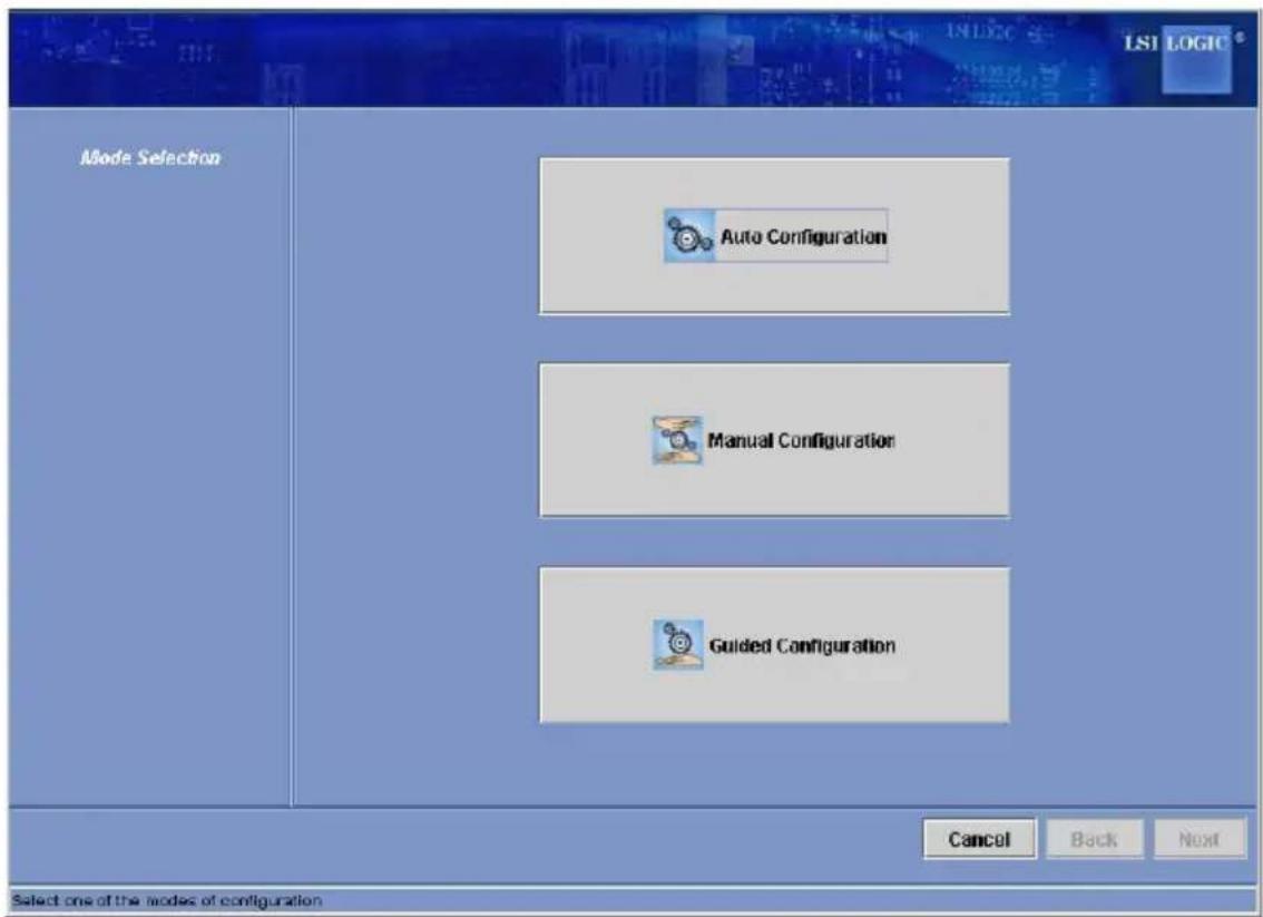
Figure 6-1: First Screen Configuration Wizard
The menu lists three configuration modes:
Auto Configuration automatically creates an optimal configuration from the available disk drives.
Manual Configuration gives you the greatest level of control in creating a new virtual disk.
Guided Configuration asks you a few simple questions about what kin configuration you want and then automatically creates it from the available disk drives.
Note: You can use Auto, Guided, or Manual mode to create a RAID 0, or RAID 1 configuration. To create a RAID 10 configuration, you must use the Configuration mode.
Understanding Virtual Disk Parameters
This section describes the Virtual Disk Parameters that you can set when you use the Guided Configuration or Manual Configuration modes of the Configuration Wizard. You should change these parameters only if you have a specific reason for doing so. It is usually best to leave them at their default settings.
Stripe Size: A stripe size of 64 Kbytes is supported.
Disk Cache Policy: Select a cache setting for this disk: Unchanged, Enabled, • or Disabled.
Init State •
- No Initialization: The new configuration is not initialized and the existing data on the disks is not overwritten.
Fast Initialization: MegaRAID Storage Manager software quickly writes zeroes to the first and last 8 Mbyte regions of the new virtual disk.
Full Initialization: A complete initialization is done on the new configuration. This may take a long time if the disks are large.
Using Auto Configuration
Auto Configuration is the quickest and simplest way to create a new storage configuration. When you select Auto Configuration mode on the first Configuration Wizard screen, the Configuration Wizard creates the best configuration possible using the available physical disks.
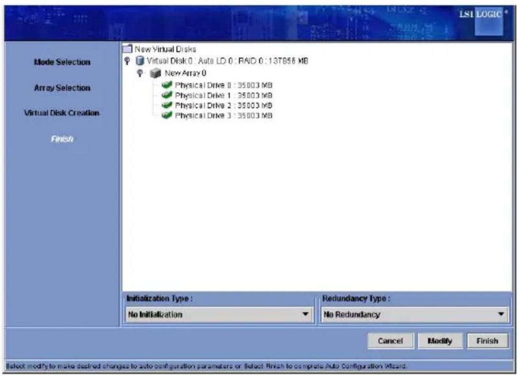
Figure 6-2: Auto Configuration Screen
Follow these steps to create a new storage configuration in Auto Config mode:
Creating a New Storage Configuration
Select a redundancy option from the drop-down menu at the bottom of the 1.
Auto Configuration window:
No Redundancy: The new configuration will have no data redundancy (RAID 0). If a physical disk in the configuration fails, all data will be lost.
With Redundancy: The new configuration will have data redundancy mirrored data (RAID 1) or via parity data (RAID 5). If a physical disk fails, data is still protected.
Select an initialization option from the drop-down menu at the bottom of the 2. window:
- No Initialization: The new configuration is not initialized, and the existing data on the disks is not overwritten.
- Fast Initialization: MegaRAID Storage Manager software quickly writes zeroes to the first and last 8 Mbyte regions of the new virtual disk
-
Full Initialization: A complete initialization is done on the new configuration. This may take a long time if the disks are large.
-
(Optional) Click Modify if you want to switch to Manual Configuration mode so you can modify the suggested Auto Configuration.
When you click Modify, the Virtual Disk Creation screen appears. Select the new virtual disk, and click Reclaim. Then select the new array from the Arrays with Free Space list, and change the virtual disk parameters as needed.
- Click Finish. The new storage configuration will be created and initialized (unless you selected No Initialization).
Using Guided Configuration
Guided Configuration provides an easy way to create a new storage configuration. Based on the information that is provided, the Configuration Wizard uses the available disk drives to create an optimal storage configuration.
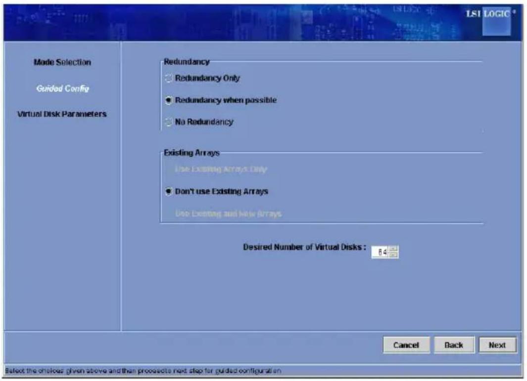
Figure 6-3: First Guided Conguration Screen
Follow these steps to create a new storage configuration in Guided Configuration mode:
Select a redundancy option at the top of the Guided Configuration window:1.
Redundancy Only: Create a configuration only if redundancy (RAID RAID 5) is possible.
Redundancy when possible: Create a redundant configuration if possil. Otherwise, create a non-redundant configuration.
No Redundancy: Create a non-redundant configuration.
Choose whether you want to use existing arrays in the new virtual disk. The 2. options are:
Use Existing Arrays Only •
Don't Use Existing Arrays •
Use Existing and New Arrays •
The first and third options are disabled if there are no available existing arrays.
Select a maximum number of virtual disks to be created. The Configuration 3. Wizard may not be able to create as many virtual disks as you want, depending on the current configuration and the number of virtual disks that have already been created.
Click Next to continue to the next window.4.
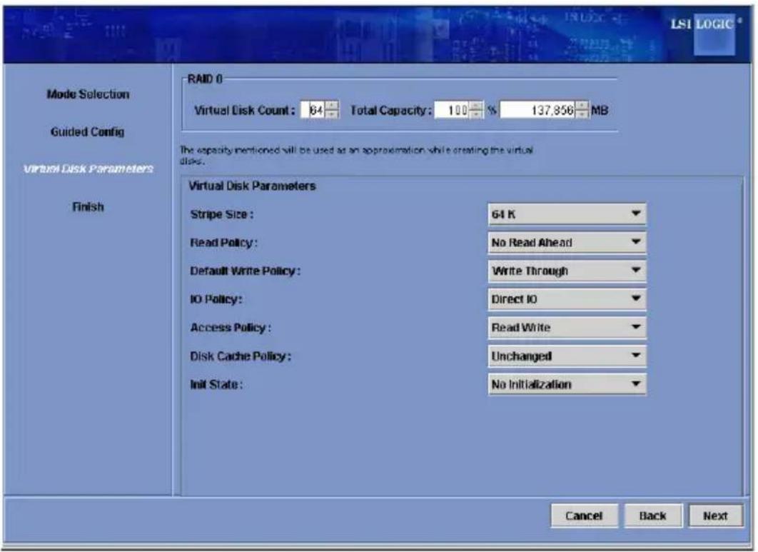
Figure 6-4: Second Guided Configuration Screen
Change the default volume parameters in this window, if needed. In the top 5. section of the window you can specify the number of virtual disks to create. You can also choose to use less than the full capacity of this array for the virtual disk(s). (You could do this to leave capacity available for other virtual disks that you create later.)
Click Next to continue to the next window.6.
Check the configuration that you have just defined. If it is acceptable, click 7. Finish. If you want to change something, click Back to return to the previous windows.
Using Manual Configuration: RAID 0
Follow these steps to create a RAID 0 storage configuration using the Configuration mode of the Configuration Wizard.
Figure 6-5 shows the first screen that appears when you select Manual Configuration.
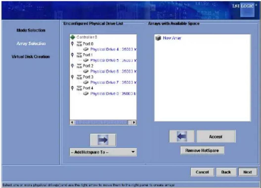
Figure 6-5: Manual Configuration - First Manual Configuration Screen
Creating a RAID 0 Storage Configuration
In the first Manual Configuration window, select two or more available drives 1. in the left panel. Click the Right Arrow button to move the selected drives to the right panel.
Note: MegaRAID Storage Manager software will not allow you to select the disk drive on which the operating system is installed or any other drives that are already part of a configuration.
Click Accept to accept these drives for the new RAID 0 array. 2.
Note: To remove a single drive from a proposed new array, select the drive icon in the right panel and click the Left Arrow button.
Click Next. 3.
The next Configuration Wizard window appears, as shown in Figure 6-6. The Arrays with Free Space menu lists the new array that you just defined, plus any existing arrays with holes (free space) that could be used for a new configuration.
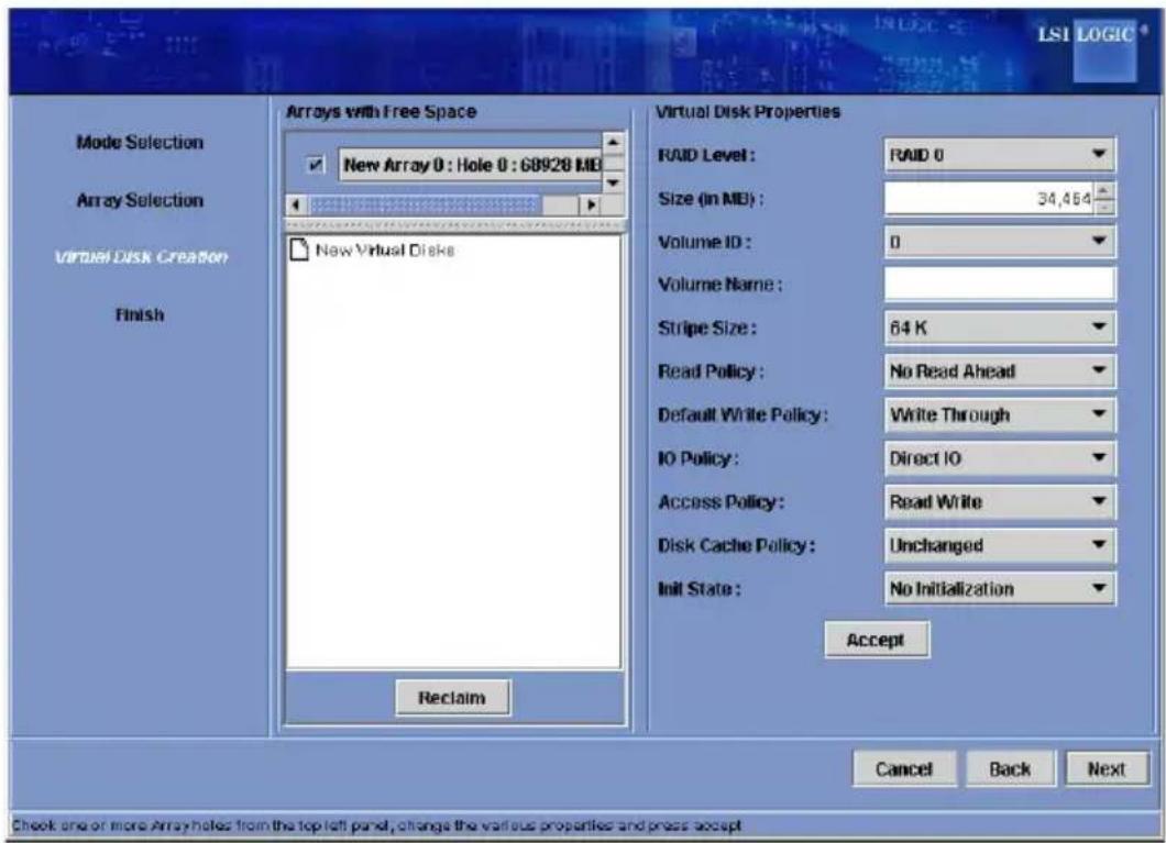
Figure 6-6: Manual Configuration - Defining a Virtual Disk
From the Arrays with Free Space menu, select the array to use for the new 4. virtual disk.
In the right panel, select RAID 0 as the RAID level.5.
(Optional) Set Size (in MB) to a lower number if you do not want to use the 6. entire available capacity for the new virtual disk.
(Optional) Change the other Virtual Disk Properties, if necessary.7.
- Click Accept to accept the configuration of the new virtual disk.
Note: Click the Reclaim button if you want to undo a virtual disk that you just defined.
- Click Next to continue with the next configuration step. The Virtual Disk Summary window appears.
Review the configuration shown in the Virtual Disk Summary window. If you 10. want to change something, click Back and change the configuration parameters
- Click Finish to accept the configuration and start the initialization process (unless you selected No Initialization earlier).
Using Manual Configuration: RAID 1
Follow these steps to create a RAID 1 storage configuration using the Configuration mode of the Configuration Wizard:
Creating a RAID 1 Storage Configuration
- In the first Manual Configuration window, shown in Figure 6-5, select two available drives in the left panel. Click the Right Arrow button to move the selected drives to the right panel.
Note: MegaRAID Storage Manager software will not allow you to select the disk drive on which the operating system is installed or any other drives that are already part of a configuration.
- Click Accept to accept these drives for the new RAID 1 array.
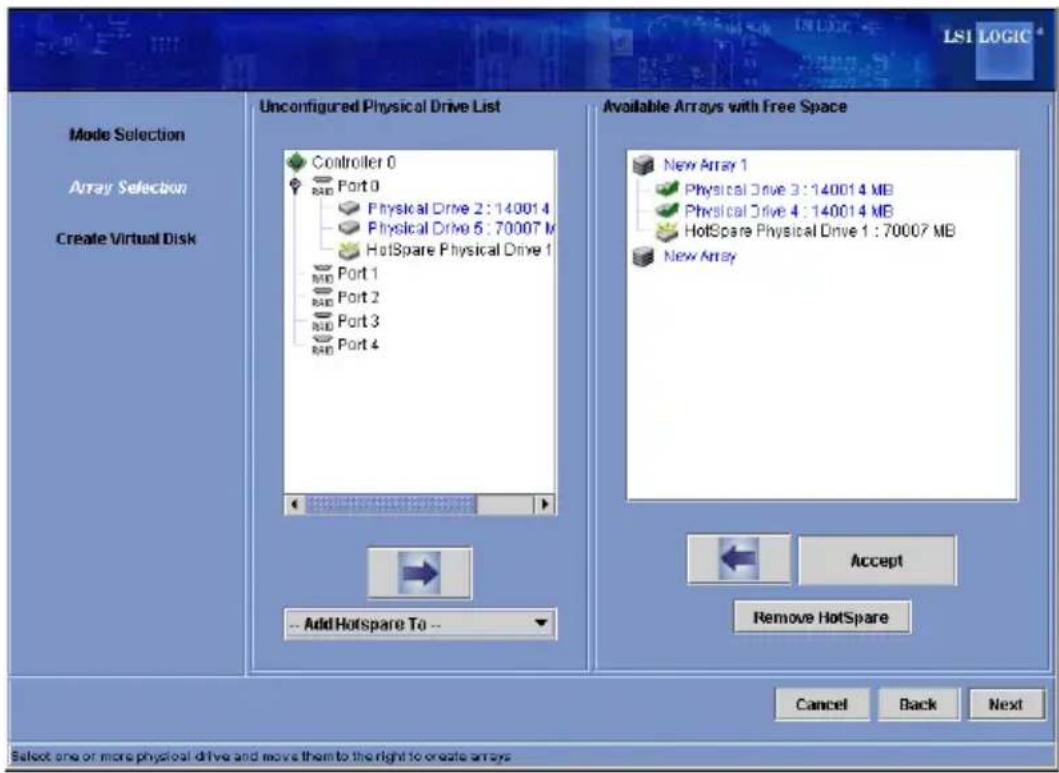
Figure 6-7: Manual Configuration - Adding a Hotspare
- To remove a hotspare from an array, select it in the right panel and click Remove HotSpare.
- Click Next.
The next Configuration Wizard window appears, as shown in Figure 6-6.
The Arrays with Free Space menus list the new array(s) that you just defined, plus any existing arrays with holes (free space) that could be used for a new configuration.
- Select the array to use for the new virtual disk.
- In the right panel, select RAID 1 as the RAID level.
- (Optional) Set Size (in MB) to a lower number if you do not want to use the entire available capacity for the new virtual disk.
- (Optional) Change the other Virtual Disk Properties, if necessary.
- Click Accept to accept the configuration of the new virtual disk.
Note: Click the Reclaim button if you want to undo a virtual disk that you just defined.
- Click Next to continue with the next configuration step.
The Virtual Disk Summary window appears.
- Review the configuration shown in the window. If you want to change something, click Back and change the configuration parameters.
Using Manual Configuration: RAID 5
Follow these steps to create a RAID 5 storage configuration using the Configuration mode of the Configuration Wizard.
Creating a RAID 5 Storage Configuration
- In the first Manual Configuration window, select three available drives in the left panel. Click the Right Arrow button to move the selected drives to the right panel.
Note: MegaRAID Storage Manager software will not allow you to select the disk drive on which the operating system is installed or any other drives that are already part of a configuration.
Click Accept to accept these drives for the new RAID 5 array.. 2.
Note: To remove a single drive from a proposed new array, select the drive icon in the right panel and click the Left Arrow button.
- Click Next. The next Configuration Wizard window appears..
The Arrays with Free Space menu lists the new array that you just defined, plus any existing arrays with holes (free space) that could be used for a new configuration.
- From the Arrays with Free Space menu, select the array to use for the new virtual disk.
In the right panel, select 5. RAID 5 as the RAID level.
-
(Optional) Set Size (in MB) to a lower number if you do not want to use the entire available capacity for the new virtual disk.
-
(Optional) Change the other Virtual Disk Properties, if necessary.
-
Click Accept to accept the configuration of the new virtual disk..
Note: Click the Reclaim button if you want to undo a virtual disk that you just defined.
- Click Next to continue with the next configuration step. The Virtual Disk Summary window appears.
Review the configuration shown in the Virtual Disk Summary window. If you 10. want to change something, click Back and change the configuration parameters.
- Click Finish to accept the configuration and start the initialization process (unless you selected No Initialization earlier).
Using Manual Configuration: RAID 10
Follow these steps to create a RAID 10 storage configuration using tl Configuration mode of the Configuration Wizard:
Creating a RAID 10 Storage Configuration Mode
In the first Manual Configuration window, shown in Figure 6-5, select two 1. available drives in the left panel. Click the Right Arrow button to move the selected drives to the right panel.
Click Accept to accept these drives for a new RAID 1 array.2.
Select two more drives for a second RAID 1 array, and click Accept.3.
To add a hotspare, select an available drive in the left panel. Select the array 4. from the drop-down menu, and click Add Hotspare To, as shown in Figure 6-7.
To remove a hotspare from an array, select it in the right panel and click 5. Remove HotSpare.
Click Next. 6.
The next Configuration Wizard window appears, as shown in Figure 6-6..
The Arrays with Free Space menu lists the new arrays that you just defined, plus any existing arrays with holes (free space) that could be used for a new configuration.
In the left panel, select the two RAID 1 arrays from the menu.7.
In the right panel, select RAID 10 as the RAID level.. 8.
For a RAID 10 array, the entire capacity of the array is automatically used for the new virtual disk. You cannot define another virtual disk on this array.
-
(Optional) Change the other Virtual Disk Properties, if necessary. For more information, see Section, "Understanding Virtual Disk Parameters."
-
Click Accept to accept the configuration of the new virtual disk.
Note: Click the Reclaim button if you want to undo a virtual disk that you just defined.
- Click Next to continue with the next configuration step. The Virtual Disk Summary window appears.
- Review the configuration shown in the window. If you want to change something, click Back and change the configuration parameters.
- Click Finish to accept the configuration and start the initialization process (unless you selected No Initialization earlier).
Using Manual Configuration: RAID 50
Follow these steps to create a RAID 50 storage configuration using the Configuration mode of the Configuration Wizard:
Creating a RAID 50 Storage Configuration
- In the first Manual Configuration window, shown in Figure 6-5, select two available drives in the left panel. Click the Right Arrow button to move the selected drives to the right panel.
Click 2. Accept to accept these drives for a new RAID 5 array. - Select two more drives for a second RAID 5 array, and click Accept.
- To add a hotspare, select an available drive in the left panel. Select the array from the drop-down menu, and click Add Hotspare To, as shown in Figure 6-7.
- To remove a hotspare from an array, select it in the right panel and click Remove HotSpare.
Click 6. Next.
The next Configuration Wizard window appears, as shown in Figure 6-6.
The Arrays with Free Space menu lists the new arrays that you just defined, plus any existing arrays with holes (free space) that could be used for a new configuration.
In the left panel, select the two RAID 5 arrays from the menu.7.
In the right panel, select RAID 50 as the RAID level. 8.
For a RAID 10 array, the entire capacity of the array is automatically used for the new virtual disk. You cannot define another virtual disk on this array.
- (Optional) Change the other Virtual Disk Properties, if necessary. For more information, see Section, "Understanding Virtual Disk Parameters."
6-2 Adding Hotspare Disks
Hotspares are disk drives that are available to automatically replace failed drives in a RAID 1, RAID 5, RAID 6 RAID 10, RAID 50, and RAID 60 virtual disk. Each virtual disk can have one dedicated hotspare.
For more information, see the LSI documentation and software Help file for more information.
Adding a Global Hotspare Disk
In the left panel of the 1. MegaRAID Storage Manager window, right click the icon of any unused disk drive.
Select 2. Make Global Hotspare.
6-3 Changing Adjustable Task Rates
Follow these steps if you need to change the adjustable rates for rebuilds and other system tasks that run in the background:
Note: LSI recommends that you leave the adjustable task rates at their default settings to achieve the best system performance. If you raise the task rates above the defaults, foreground tasks will run more slowly and it may seem that the system is not responding. If you lower the task rates below the defaults, rebuilds and other background tasks may run very slowly and may not complete within a reasonable time. If you decide to change the values, record the original default value here so you can restore them later, if necessary:
Rebuild Rate: ____
Background Initialization (BGI) Rate: ____
Check Consistency Rate: ____
- Select the Physical View tab in the left panel of the MegaRAID Storage Manager window, and select a controller icon.
- In the right panel of the MegaRAID Storage Manager window, select the Operations tab, and select Set Adjustable Task Rates.
The task rates appear in the right panel.
-
Enter changes, as needed, to the task rates for Rebuild Rate, Background Initialization (BGI) Rate (for fast initialization), and Check Consistency Rate (for consistency checks). Each task rate can be set from 0 to 100. The higher the number, the faster the activity will run in the background, possibly impacting other system tasks.
-
Click Go to accept the new task rates.
-
When the warning message appears, click OK to confirm that you want to change the task rates.
6-4 Changing Virtual Disk Properties
You can change a virtual disk's Read Policy, Write Policy, and other properties at any time after the virtual disk is created. To do this, follow these steps:
- Select a virtual disk icon in the left panel of the MegaRAID Storage Manager window.
- In the right panel, select the Properties tab, and then select Set Virtual Disk Properties.
A list of Virtual Disk Properties appears in the right panel.
- Change the virtual disk properties as needed in the right panel. For information on these properties, see Section "Understanding Virtual Disk Parameters"
Note: Only the Disk Write Cache and Read Ahead functions are supported in Embedded MegaRAID Software.
- Click Go to accept the changes.
6-5 Deleting a Virtual Disk
Caution: Be sure to back up the data on the virtual disk before you delete it. Be sure that the operating system is not installed on this virtual disk.
You can delete virtual disks to rearrange the storage space. To delete a virtual disk, follow these steps:
- Back up all user data that is on the virtual disk you intend to delete.
- In the left panel of the MegaRAID Storage Manager window, select the Logical tab, and click the icon of the virtual disk you want to delete.
- In the right panel, select the Operations tab, and select Delete Virtual Disk.
- Click Go.
- When the warning message appears, click Yes to confirm that you want to delete the virtual disk.
6-6 Saving a Storage Configuration to Disk
You can save an existing controller configuration to a file so you can another controller.
Saving a Configuration File
Select a controller icon in the left panel of the MegaRAID Storage Manager 1. window.
- On the menu bar, select Operations, Advanced Operations, Configuration, Save Configuration.
The Save dialog box appears.
- In the Save dialog box, type a name for the configuration file, or accept the default name (hostname.cfg).
Click 4. Save to save the configuration file.
6-7 Clearing a Storage Configuration from a Controller
You can use the Add New Configuration option to add a new storage configuration while keeping the existing configuration. Alternatively, you can clear the existing storage configuration from a controller and then create a totally new configuration or load a previously saved configuration file.
Caution: Before you clear a configuration, be sure to save any data want to keep. Clearing a configuration deletes all data from the disks existing configuration. Be sure that the operating system is not installed on this configuration.
Clearing a Configuration from the Controller
-
Select a controller icon in the left panel of the MegaRAID Storage Manager window.
-
On the menu bar, select Operations, Advanced Operations, Configuration, Clear Configuration. A Warning message appears.
-
Click Yes to clear the configuration or No to cancel the operation.
6-8 Adding a Saved Storage Configuration
When you replace a controller, or when you want to duplicate an existing storage configuration on a new controller, you can add a saved configuration controller.
Caution: When you add a saved configuration to a replacement contro sure that the number and size of the physical disks connected to the controller are exactly the same as when the configuration was saved.
Adding a Saved Configuration
- Select a controller icon in the left panel of the MegaRAID Storage Manager window.
- On the menu bar, select Operations, Advanced Operations, Configuration, Add Saved Configuration. A Warning message appears.
Click 3. Yes.
When the Open dialog box appears, select the configuration file, and click 4. Open.
- View the configuration detail, then select Apply.
Confirm the new configuration when prompted.6.
Disclaimer (cont.)
The products sold by Supermicro are not intended for and will not be used in life support systems, medical equipment, nuclear facilities or systems, aircraft, aircraft devices, aircraft/emergency communication devices or other critical systems whose failure to perform be reasonably expected to result in significant injury or loss of life or catastrophic property damage. Accordingly, Supermicro disclaims any and all liability, and should buyer use or sell such products for use in such ultra-hazardous applications, it does so entirely at its own risk. Furthermore, buyer agrees to fully indemnify, defend and hold Supermicro harmless for and against any and all claims, demands, actions, litigation, and proceedings of any kind arising out of or related to such ultra-hazardous use or sale.
- WARNING: Handling of lead solder materials used in this product may expose you to lead, a chemical known to the State of California to cause birth defects and other reproductive harm.
- Table of Contents
- Introduction
- Chapter 1 Safety Guidelines
- Chapter 2 Connectors and LED Indicators
- Chapter 3 WebBIOS Configuration
- Chapter 4 MegaRAID Storage Manager Software Overview and Installation
- Chapter 5 MegaRAID Storage ManagerWindow and Menus
- Chapter 6 Configuration
- Overview
- Product Features
- Operating Systems Supported
- Manual Images
- Contacting Supermicro
- Returning Merchandise for Service
- Notes
- Chapter 1
- Safety Guidelines
- 1-1 ESD Safety Guidelines
- 1-2 General Safety Guidelines
- 1-3 An Important Note to Users
- Chapter 2
- Connectors and LED Indicators
- 2-1 Front Connectors and Jumpers
- Front Connectors
- Front SAS Connectors
- 2-2 Front Connector and Pin Definitions
- Internal SAS Connector (Drive 0-3)
- Internal SAS Connector (Drive 4-7)
- I-Button
- Board-to-Board Connector
- 2-3 LED Functions
- RAID Minimum Drive Requirements
- Chapter 3
- WebBIOS Configuration
- 3-1 Introduction
- 3-2 Accessing the WebBIOS
- 3-3 WebBIOS Configuration Wizard
- Starting the Configuration Wizard
- WebBIOS Configuration Wizard - Auto Configuration
- WebBIOS Configuration Wizard - Custom Configuration
- Stripe Size
- 3-4 Device Properties
- Adapter Properties
- Virtual Disk Properties
- Physical Drive Properties
- Battery Backup Unit
- System Event Information
- Do the following to view event information:
- Chapter 4
- MegaRAID Storage Manager Software Overview and Installation
- 4-1 Overview
- Creating Storage Configurations
- Maintaining Storage Configurations
- 4-2 Hardware and Software Requirements
- 4-3 Installation
- Installation
- Installing MegaRAID Storage Manager Software for Linux
- Installing MegaRAID Storage Manager
- Linux Error Messages
- Chapter 5
- MegaRAID Storage Manager Window and Menus
- 5-1 Starting MegaRAID Storage Manager Software
- Starting MegaRAID Storage Manager
- 5-2 MegaRAID Storage Manager Window
- Physical/Logical View Panel
- Event Log Panel
- Menu Bar
- File Menu
- Operations Menu
- Group Operations Menu
- Log Menu
- Help Menu
- Chapter 6
- Configuration
- 6-1 Creating a New Storage Configuration
- Understanding Virtual Disk Parameters
- Using Auto Configuration
- Creating a New Storage Configuration
- Using Guided Configuration
- Using Manual Configuration: RAID 0
- Creating a RAID 0 Storage Configuration
- Using Manual Configuration: RAID 1
- Using Manual Configuration: RAID 5
- Creating a RAID 5 Storage Configuration
- Using Manual Configuration: RAID 10
- Creating a RAID 10 Storage Configuration Mode
- Using Manual Configuration: RAID 50
- Creating a RAID 50 Storage Configuration
- 6-2 Adding Hotspare Disks
- Adding a Global Hotspare Disk
- 6-3 Changing Adjustable Task Rates
- 6-4 Changing Virtual Disk Properties
- 6-5 Deleting a Virtual Disk
- 6-6 Saving a Storage Configuration to Disk
- Saving a Configuration File
- 6-7 Clearing a Storage Configuration from a Controller
- Clearing a Configuration from the Controller
- 6-8 Adding a Saved Storage Configuration
- Adding a Saved Configuration
- Disclaimer (cont.)
Brand : Supermicro
Model : AOC-SASLP-H8IR
Category : Controller