VG2790 - Sewing machine Yamato - Free user manual and instructions
Find the device manual for free VG2790 Yamato in PDF.


| Product Type | Sewing Machine |
| Brand | Yamato |
| Model | VG2790 |
| Dimensions (approx.) | 40 x 18 x 28 cm |
| Weight | 5.5 kg |
| Power Supply | 220-240V, 50/60 Hz |
| Power Consumption | 90 W |
| Stitch Types | Straight, Zigzag, Buttonhole, Blind Hem, Stretch Stitches |
| Number of Stitches | 15 |
| Buttonhole Style | 4-Step Automatic |
| Needle System | Standard HAx1 (130/705H) |
| Bobbin Type | Top Drop-in, Transparent |
| Feed Dogs | 7-tooth, Drop Feature Available |
| Maximum Sewing Speed | 750 stitches per minute |
| Stitch Length | Adjustable, 0-4 mm |
| Stitch Width | Adjustable, 0-5 mm |
| Lighting | LED Built-in Light |
| Safety Features | Safety Power Switch, Finger Guard |
| Maintenance | Clean bobbin area after each project; oil moving parts every 8 hours of use |
| Accessories Included | Needle set, bobbins, seam ripper, screwdrivers, oil bottle, foot pedal |
| Spare Parts | Needles, bobbins, presser feet, belts (user-replaceable) |
| Reparability | User-serviceable: needle plate, presser foot, bobbin case; professional service for motor/electronics |
| Warranty | 2 years limited |
Frequently Asked Questions - VG2790 Yamato
User questions about VG2790 Yamato
0 question about this device. Answer the ones you know or ask your own.
Ask a new question about this device
Download the instructions for your Sewing machine in PDF format for free! Find your manual VG2790 - Yamato and take your electronic device back in hand. On this page are published all the documents necessary for the use of your device. VG2790 by Yamato.
USER MANUAL VG2790 Yamato
Thank you for purchasing the VG2790. Before using your VG2790, please read the instruction manual and understand the contents well.
After reading the instruction manual, please keep it in a location where it is easily accessible to the operator.
Safety instructions
i - iv
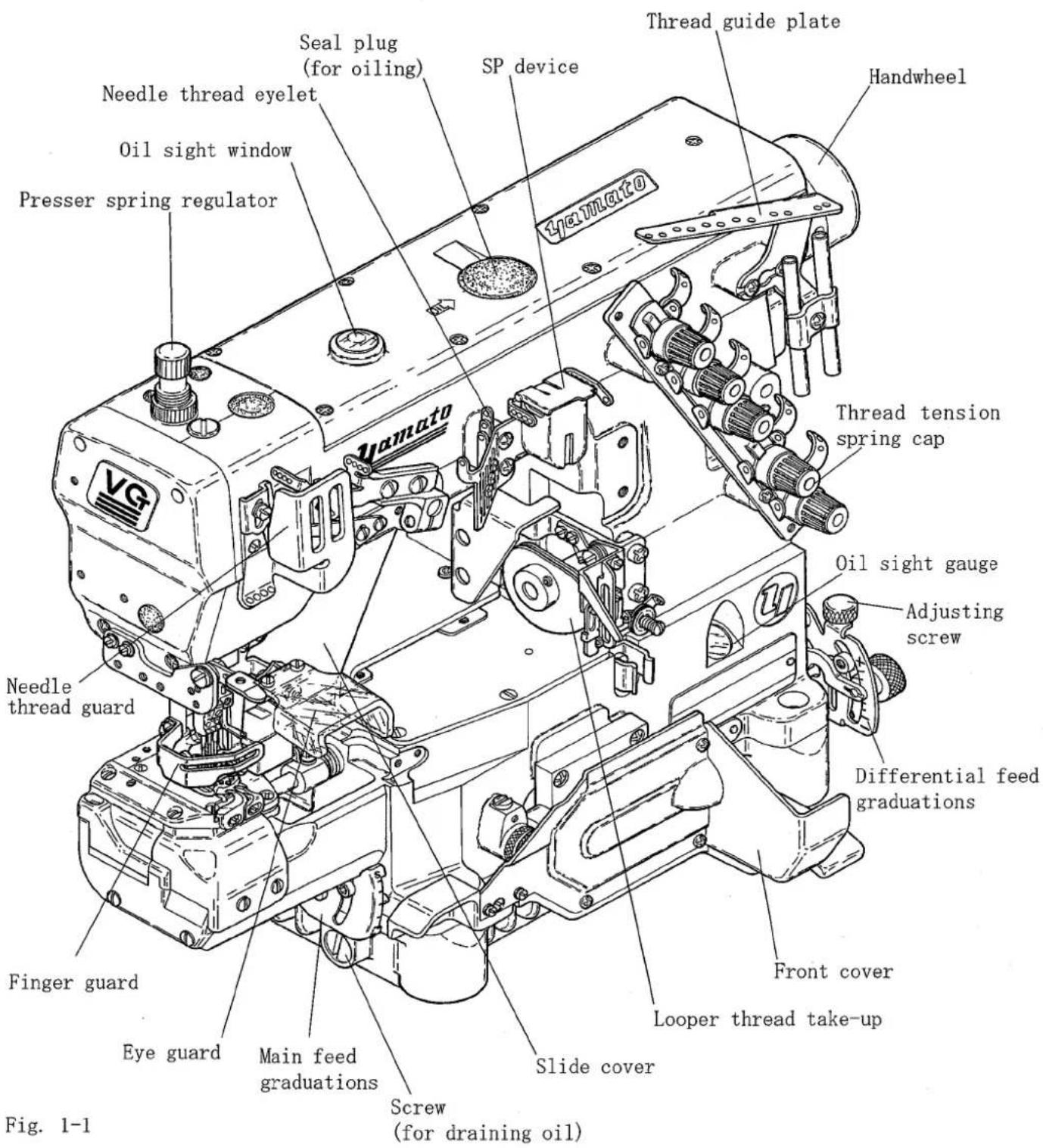
1. Name of each part
1
2. Installation
2
| 2.1 | Table cutting diagram | 2 |
| 2.1.1 | Table top type (Type A: standard) | 2 |
| 2.1.2 | Table top type (Type B) | 3 |
| 2.1.3 | Semi-submerged type | 4 |
| 2.1.4 | Semi-submerged type with compact motor | 5 |
| 2.2 | Table top type | 6 |
| 2.3 | Semi-submerged type | 6 |
| 2.4 | Motor, belt and pulley | 7 |
| 2.5 | Hanging belt | 8 |
| 2.6 | Belt cover | 8 |
| 2.7 | Eye guard and finger guard | 9 |
3. Sewing speed and rotating direction of pulley 10
4. Lubrication
11
| 4.1 | Lubricating oil | 11 |
| 4.2 | Lubricating | 11 |
| 4.3 | Changing oil | 12 |
| 4.4 | Checking and replacing oil filter | 12 |
5. Proper operation
13


| 5.1 | Needle system | 13 |
| 5.2 | Installing needles | 13 |
| 5.3 | Threading | 14 |
| 5.4 | Adjusting thread tension | 15 |
| 5.5 | Pressure of presser foot | 15 |
| 5.6 | Adjusting position of presser foot | 15 |
| 5.7 | Adjusting movement of differential feed dog | 16 |
| 5.8 | Adjusting stitch length | 17 |
| 5.9 | Raising upper feed roller (for machine with puller mechanism) | 18 |
| 5.10 | Pressure of upper feed roller (for machine with puller mechanism) | 18 |
| 5.11 | SP device | 19 |
| 5.12 | Cleaning the machine | 19 |
6. Adjustment 20
| 6.1 | Needle thread tension | 20 |
| 6.2 | Top cover thread tension | 21 |
| 6.3 | Looper thread tension | 21 |
| 6.4 | Relation between needle and spreader | 22 |
| 6.4.1 | Spreader | 22 |
| 6.4.2 | Top cover thread guide | 23 |
| 6.4.3 | Top cover thread eyelet | 23 |
| 6.5 | Distance between needle and looper | 24 |
| 6.6 | Using timing gauge | 24 |
| 6.7 | Height of needle | 25 |
| 6.8 | Front-and-rear position of needle and looper | 25 |
| 6.9 | Needle and needle guard(rear) | 26 |
| 6.10 | Needle and needle guard(front) | 28 |
| 6.11 | Height of feed dog | 29 |
| 6.12 | Changing range of differential ratio | 29 |
| 6.12.1 | Differential ratio 1:1.1 - 1:2 | 29 |
| 6.12.2 | Differential ratio 1:0.7 - 1:1.4 | 30 |
| 6.13 | Presser foot lift | 32 |
| 6.14 | Feeding amount of puller (for machine with puller mechanism) | 33 |
| 6.15 | Pressure of clutch tension spring (for machine with puller mechanism) | 33 |
7. Specifications 34
Attention
This instruction manual is designed mainly for technicians, but it is advisable that also operators read the instructions with mark to use the machine properly.
◇ The numbers in lower left corners of figures are figure numbers. We use them in texts as needed for your reference.
Attention
The description in this instruction manual is subject to change for improvements of the commodity without notice.
1. To ensure safe use
Always observe the following instructions to ensure the safe use of the industrial sewing machines and devices.
1-1 Application and purpose
The sewing machine is designed to improve productivity in the sewing industry and must not be used for other applications and purposes. Do not use this sewing machine until it can be confirmed that safety measures for the drive units have been taken.
1-2 Before use
Read all instruction manuals thoroughly before starting the use of this machine and follow them.
Also, read the instruction manual for the installed drive unit.
1-3 Working environment
DO NOT WORK IN THE FOLLOWING ENVIRONMENTS:
- Place where atmosphere temperature and humidity give a bad influence the performance of sewing machines.
- Outdoors and place where the sewing machines are exposed to sunlight directly.
- Atmosphere containing dust, corrosive gases or flammable gases.
- Place where voltage fluctuation exceeds ± 10 % of the rated voltage.
- Place where power capacity necessary for the used motor specifications cannot be secured.
- Place where strong electric or magnetic fields are generated such as near large-output high frequency transmitters or high frequency welding machines.
1-4 Unpacking and transportation
(1) Unpack from the top.
(2) Never hold the parts near the needle or threading parts when removing the sewing machine head from the buffer of box.
(3) When carrying the sewing machine head, have an assistant.
(4) Pay attention not to get excessive impact or shock when moving the sewing machine
head with a pushcart.
2. Installation and preparation
2-1 Instruction and training
Operators and workers, who supervise, repair or maintain the machine head and machine unit, are required to have the adequate knowledge and operation skills to do the job safely. In order to establish such necessary conditions, it needs for the employer to plan and enforce the safety education and training to those workers.
2-2 Sewing table and motor
(1) Prepare a machine table that has enough strength to withstand the weight of the sewing head and any reaction while operating.
(2) Maintain a comfortable working environment with considering the lighting and the arrangement of sewing machine so that the operators can work smoothly.
(3) When installing the control box and the related parts on the sewing machine, take care about the posture of the worker.
(4) Install the drive unit correctly according to the instruction manual.
2-3 Wiring
(1) Never connect the plug for power supply until assembly is finished.
(2) Fix the connectors securely to the sewing machine head, motor, and electric apparatus.
(3) Do not apply excessive force to the connection cords.
(4) Connect the cords away from the driving parts.
(5) Place the ground wire securely to the designated position on the machine head.
2-4 Before operation
(1) Take care not to attach lubricant, silicone oil, and grease on the eyes or skin.
Keep them away from children.
(2) Be sure to fill or drop lubrication oil before operating the sewing machine. Use the Yamato SF oil as specified.
(3) Never put your hand under the needle or near the moving parts of the machine when turning on power supply switch.
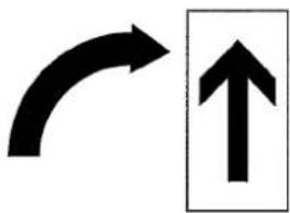
(4) When operating a new sewing machine, make sure the rotating direction of pulley agrees with the rotating-direction mark.
2-5 During operation
(1) Be sure to operate the sewing machine with the safeguards such as belt cover, finger guard, and eye guard.
(2) Never place the finger, hair or objects under the needle or close to the moving parts while operating the sewing machine.
(3) Be sure to turn off the power supply switch when threading or replacing the needles.
(4) Never place your hands close to the knives when operating the sewing machine with the trimming devices.
(5) Be sure to turn off the power supply switch when terminating the sewing work or leaving the sewing machine.
(6) If the sewing machine malfunctions, abnormal sound or smell something unusual while operating, be sure to turn off the power supply switch.
2-6 Removal
(1) Turn off the power supply switch if removed or replaced any parts or during adjustment of sewing machine.
(2) Do not pull the cord when removing the plug. Be sure to hold the plug itself.
(3) A high voltage is applied inside the control box. Turn off the power supply switch and wait more than 5 minutes before opening the cover.
3. Maintenance, inspection, and repair
(1) Follow the instruction manuals for maintenance, inspection, and repair.
(2) Entrust the maintenance, inspection, and repair to specially trained personnel.
(3) Be sure to turn off the power supply switch and make sure the sewing machine and motor completely stop before the maintenance, inspection, and repair. (If using a clutch motor, take care that the motor keeps turning for a while even after turning off the power supply switch.)
(4) Do not modify the sewing machine by the customer's judgment.
(5) Be sure to use original replacement parts for repairs or maintenance.
4. Caution signs and alert pictorial markings
This instruction manual contains the following caution signs and alert pictorial markings to prevent you from injuring yourself or the sewing machine from being damaged.
Please follow the instructions.
4-1 Meanings of caution signs
WARNING indicates potentially hazardous situations which, if not heeded, could result in death or serious injury to you and others.
Caution indicates hazardous situations which, if not heeded, may result in minor or moderate injury to you and others, or may result in machine damage.
NOTE is used to emphasize essential information.
4-2 Alert pictorial markings

This mark indicates the warning which, if not heeded, could result in death or Serious injury.

This mark indicates the caution for high temperature.

This mark indicates the warning which, if not heeded, could result in death or Serious injury.

High-voltage applies in the control box. This label indicates that electric shock may be caused.

This mark indicates the caution which, if not grounded, the machine or device could malfunction and could result in personal injury.
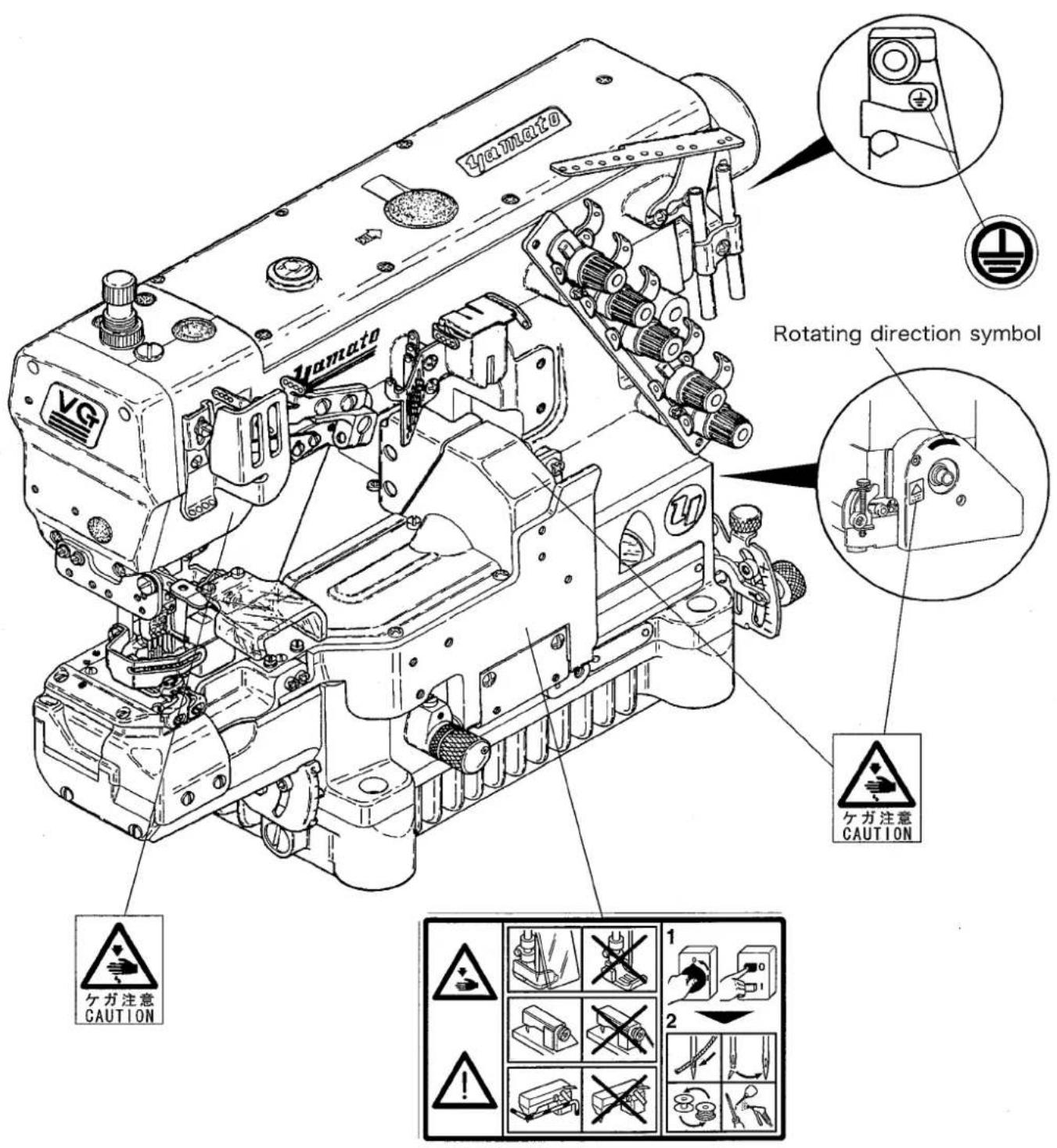
5. Warning labels on sewing machines
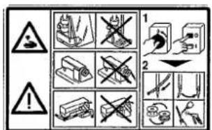
This label indicates that removal of the safeguards and works except for sewing performance while the power supply switch is on are prohibited. (For details, see the next page.)
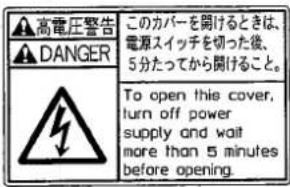
High-voltage applies in the control box. This label indicates that electric shock may be caused.
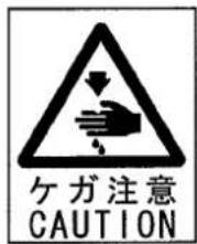
This label is affixed on the safeguards. Considering the operation, it is not affixed on the finger guard and eye guard. Be sure to

Stepping motor and solenoid may overheat if used continuously. To prevent a burn, take care not to touch.

If not connected earth line, static electricity may be generated and inflict injury on person. In addition, the malfunction of
natural_image
Two black arrows pointing in opposite directions: one curved and one upward, with no text or symbols present.Check the rotating direction of machine pulley agrees with 'ROTATING-DIRECTION SYMBOL'.
1. Name of each part
2.1 Table cutting diagram
2.1.1 Table top type (Type A: standard)
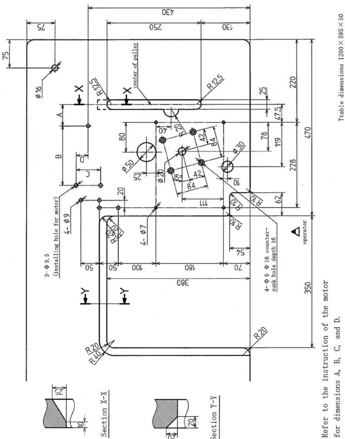
Fig. 2-1
2.1.2 Table top type (Type B)
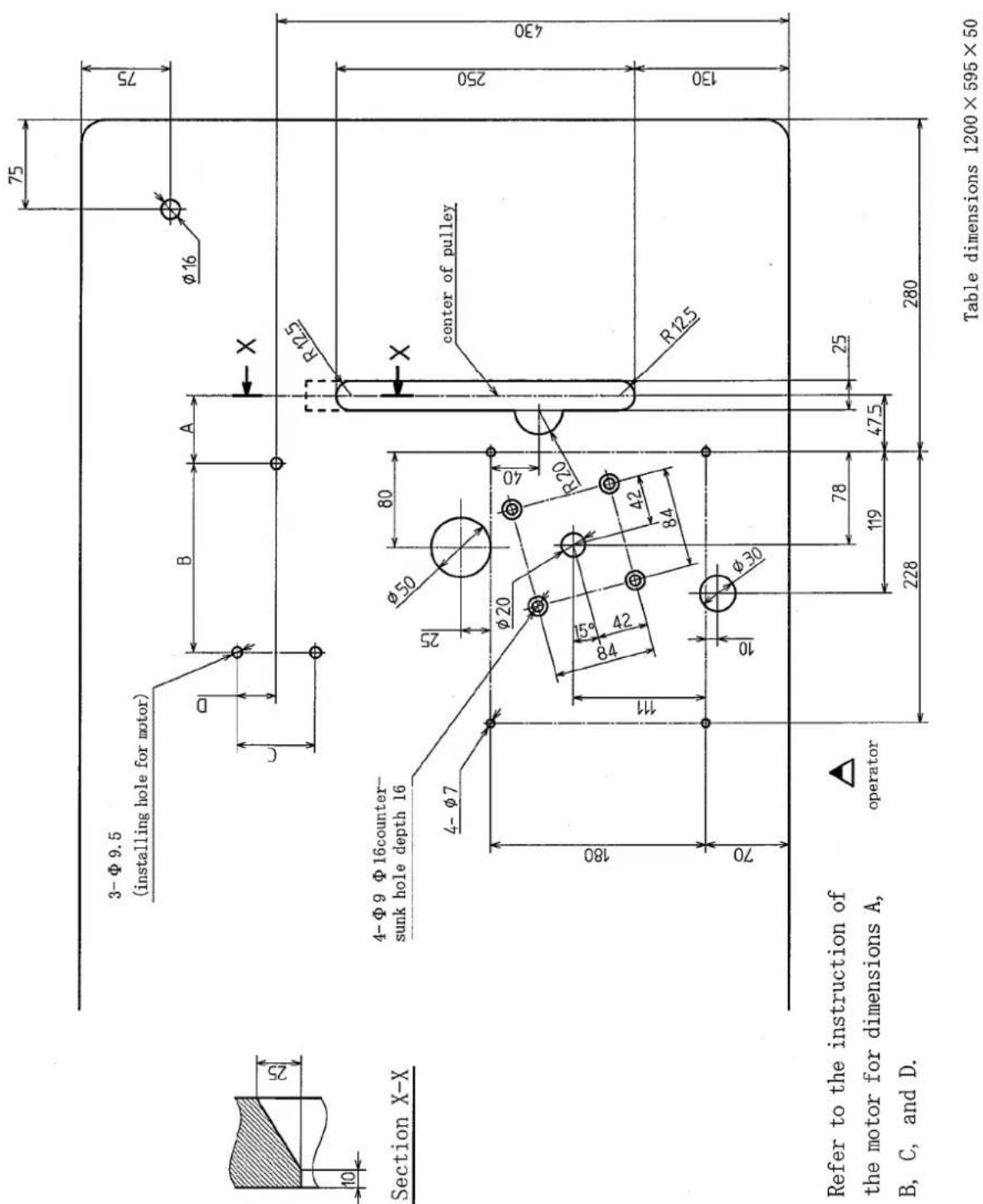
Fig. 2-2
2.1.3 Semi-submerged type
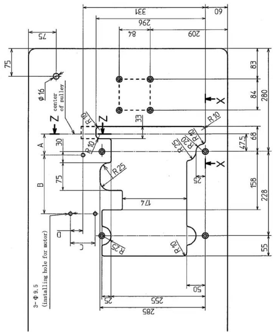
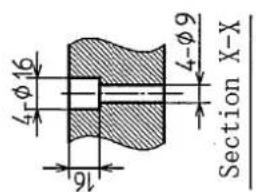
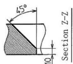
Refer to the instruction of the motor for dimensions A, B, C, and D
Table dimensions 1200 × 540 × 40
Fig. 2-3
2.1.4 Semi-submerged type with compact motor
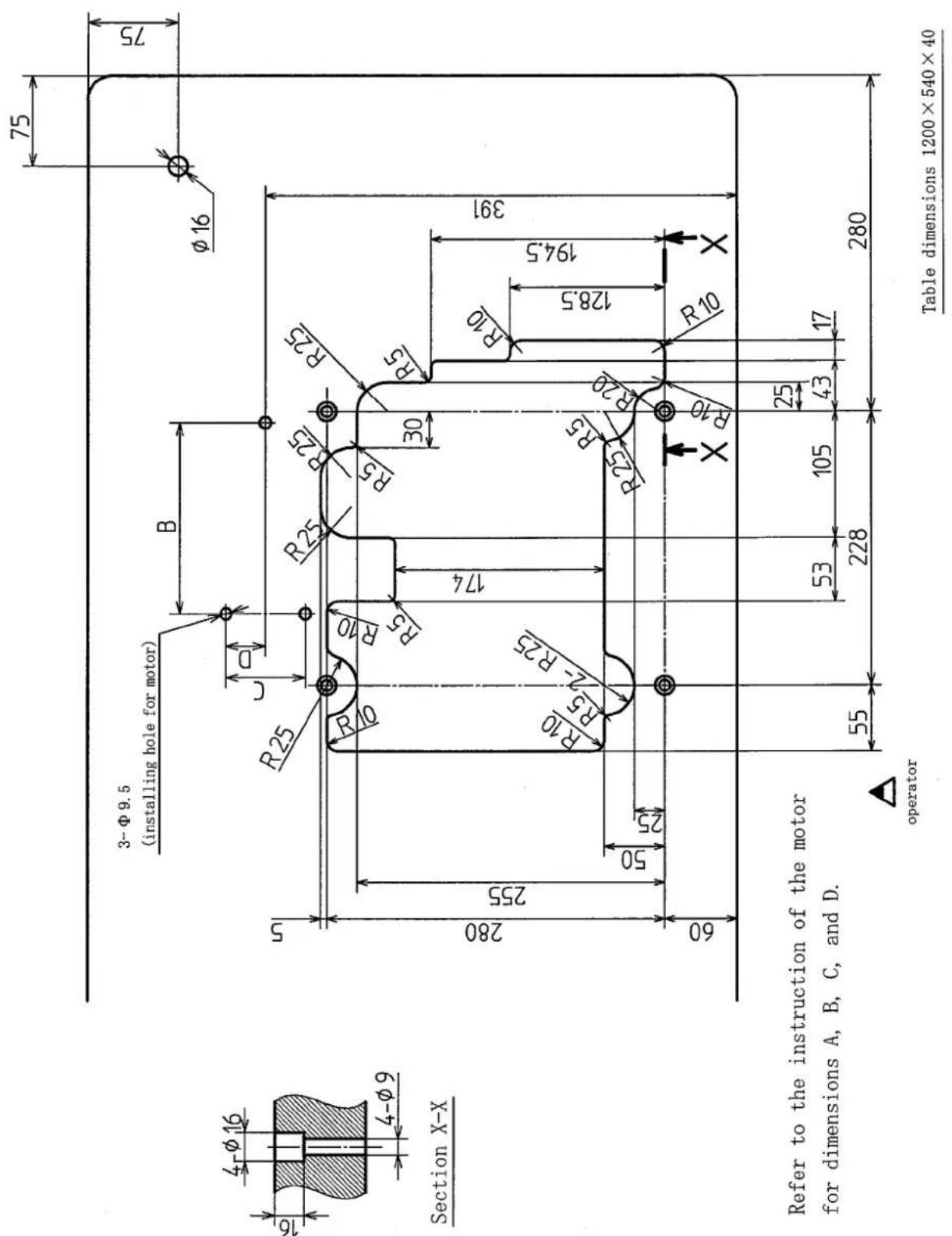
Fig. 2-4
2.2 Table top type
Install the machine correctly by referring to Fig. 2-5, 2-6.
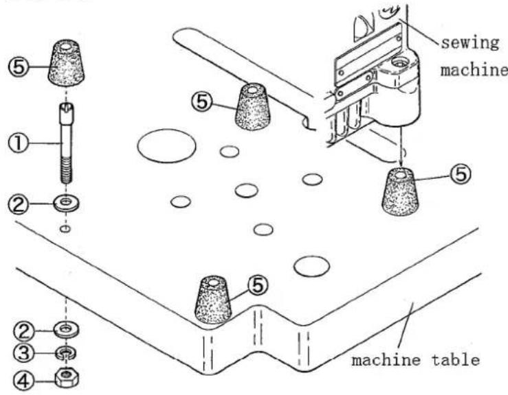
Fig. 2-5
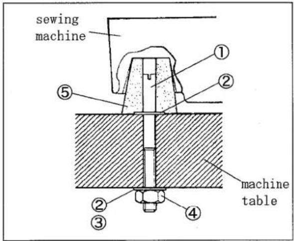
Fig. 2-6
2.3 Semi-submerged type
Install the machine correctly by referring to Fig. 2-7, 2-8.
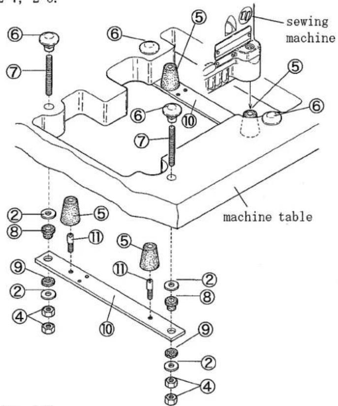
Fig. 2-7
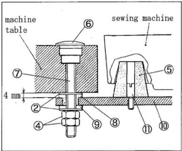
Fig. 2-8
2.4 Motor, belt and pulley
Follow the instruction manual for the motor to use and install the motor properly.
To install the clutch motor, align the center of the machine pulley with that of the motor pulley when the motor pulley shifts to the left by toeing down the pedal.
Note: Table 1 shows the outside diameter of the motor pulley, rpm of the machine, and size of the belt when using the clutch motor of 3-phase, 2-pole, 550W(3/4HP). The outside diameter on the table shows the nearest size to the calculated values based on the commercial available pulleys at intervals of 5 mm.

CAUTION
Use only those motor pulleys which apply to the machine. If not, the sewing speed will be over maximum and it can cause the damage to the machine.
Servomotor:
Calculate the outside diameter of a motor pulley from the following formula.
Or see Table 2 to select a proper motor pulley.
$$ \text { Outside diameter of motor pulley } = \frac {\text { Usual sewing speed }}{\text { Servomoter speed }} \times 6 4. 5 + 5 \mathrm{mm} $$
Belt
Use a V-belt of M type.
For belt size, refer to Table 1.
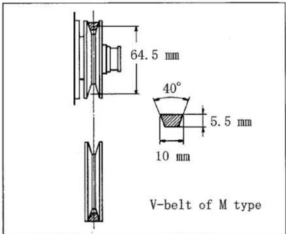
Fig. 2-9
| Outside diameter of pulley (mm) | rpm of machine | Size of belt | ||
| 50Hz | 60Hz | Table top | Semi-submerged | |
| 90 | 4600 | 40 | 33 | |
| 95 | 4850 | 40 | 34 | |
| 100 | 5100 | 41 | 34 | |
| 105 | 4550 | 5350 | 41 | 34 |
| 110 | 4750 | 5600 | 41 | 35 |
| 115 | 5000 | 5850 | 42 | 35 |
| 120 | 5200 | 6150 | 42 | 35 |
| 125 | 5400 | 6400 | 42 | 36 |
| 130 | 5600 | 43 | 36 | |
| 135 | 5800 | 43 | 36 | |
| 140 | 6000 | 43 | 37 | |
| 145 | 6300 | 44 | 37 | |
| 150 | 6500 | 44 | 37 | |
Table 1
| rpm of machine (rpm) | Outside diameter of motor pulley (mm) | |
| rpm of servomotor | ||
| 3000 rpm | 3600 rpm | |
| 4200 | 95 | 80 |
| 4500 | 102 | 86 |
| 4700 | 106 | 89 |
| 5000 | 113 | 95 |
| 5200 | 117 | 98 |
| 5500 | 123 | 104 |
| 5800 | 130 | 109 |
| 6000 | 134 | 113 |
| 6200 | 138 | 116 |
| 6500 | 145 | 121 |
Table 2
2.5 Hanging belt

WARNING
Before hanging belt, ALWAYS turn the power switch OFF and check that the machine has already stopped.
Use the V-belt of M type.
(1) Hang the belt① on the machine pulley②, and then on the motor pulley③ while rotating the machine pulley.
(2) Adjust the belt tension so that the belt has 10 - 20 mm slack when its center is pushed with 10N(1.02kgf).
(3) Lock the pulley with the nut④.

Fig. 2-10
2.6 Belt cover

WARNING
Be sure to install the belt cover to prevent you from getting injured and a material from being caught by the belt.
(1) Install the belt cover①. (See Fig. 2-11)
(2) Install the belt cover support ② and make it touch the belt cover① tightly. (See Fig. 2-12)
(3) Fix the belt cover(lower)③ onto the machine table only for table top type. (See Fig. 2-13)
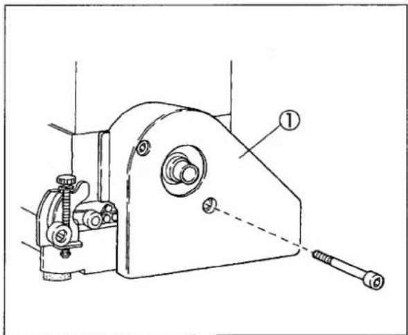
natural_image
Technical line drawing of a mechanical device with labeled parts (no text or symbols beyond label)Fig. 2-11
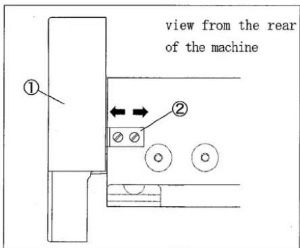
Fig. 2-12
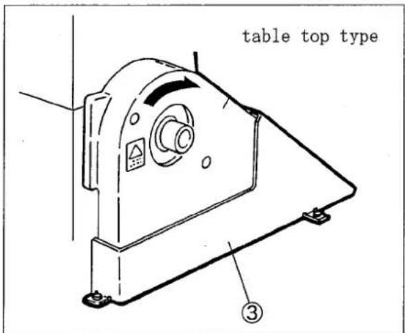
Fig. 2-13
2.7 Eye guard and finger guard
To ensure the safe use, always install the eye guard① and the finger guard② onto the prescribed position during operation.
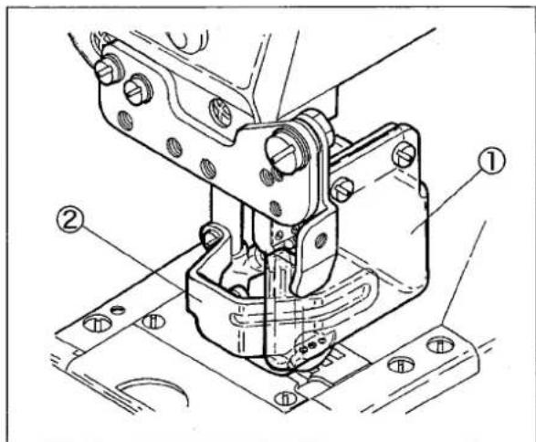
Fig. 2-14
3. Sewing speed and rotating direction of pulley
The maximum sewing speed is 6500 rpm (during intermittent operation) (the models with puller is 5000 rpm). Run a new machine at 15-20% lower rotating speed of its maximum sewing speed during the first 200 hours (for about one month) so that the machine can offer a long service life in good condition.
The rotating directions of the machine pulley ① and the handwheel ② are clockwise as shown in the figure.
CAUTION
If the machine pulley reverses, oil cannot be supplied properly. This may cause damage to the machine.
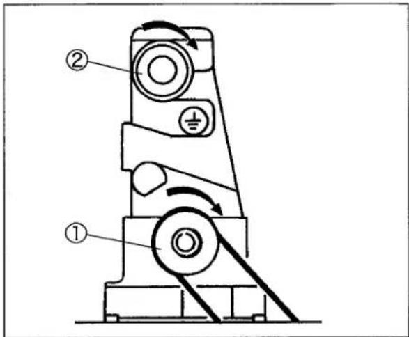
Fig. 3-1
4. Lubrication

WARNING
Before lubricating, ALWAYS turn the power switch OFF and check that the machine has already stopped.
4.1 Lubricating oil
Use YAMATO SF OIL No. 28.

CAUTION
Never add additives to the oil. If added, it can cause the deterioration of the oil and troubles of the machine.
4.2 Lubricating
When using a new machine, or a machine which has not been run for a while, supply the oil to the needle bar ① and the looper bar ② with two or three drops.
Remove the seal plug③ indicated "OIL" and supply the oil to the upper line of the oil sight gauge④.
Make sure that the oil splashes from the nozzle inside the oil sight window⑤ when running the machine. If the oil does not splash from the nozzle, see "4.4 Checking and replacing oil filter" on page 12.

CAUTION
Too much or insufficient oil can cause oil leakage and machine trouble. Be sure to keep the oil level between the lines. Also too much lubrication can cause oil scatter and material stain.
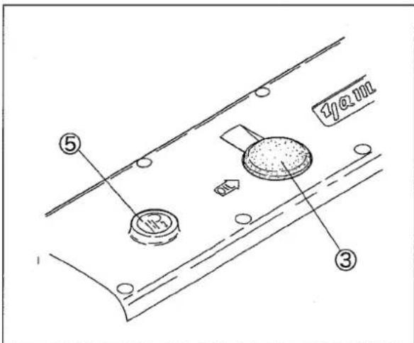
Fig. 4-3
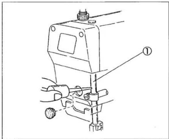
Fig. 4-1
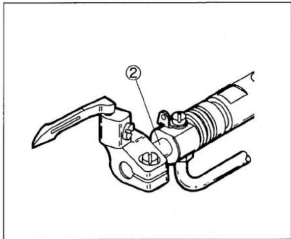
Fig. 4-2
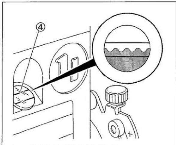
Fig. 4-4

WARNING
Before lubricating, ALWAYS turn the power switch OFF and check that the machine has already stopped.
4.3 Changing oil
Timing:
When using a new machine, change the lubricating oil after running the machine for 250 hours (for about one month). After that, change the oil once or twice a year.
Procedure:
(1) Remove the belt cover. (See page 8)
(2) Remove V-belt from the motor pulley. (See page 8)
(3) Remove the machine from the machine table.
(4) Set a container under the screw① to receive the oil.
(5) After removing screw①, the oil will drain out.
NOTE
Be careful not to soil the V-belt and the machine pulley with the oil.
(6) Screw back the screw①.
(7) Change the oil. (See “4.2 lubricating” on page 11)
(8) Reinstall the machine on the machine table.
(9) Hang the V-belt back onto the motor pulley and reinstall the belt cover. (See page 8)
4.4 Checking and replacing oil filter
◆ If the oil filter② is clogged with dust, lubrication cannot be done properly.
◆ Remove the oil filter cap③ and the oil filter ② to check them every six months. If clogged or cracked, clean or replace the oil filter.
If the oil splashes from the nozzle insufficiently or includes many bubbles though the oil is sufficiently kept, check or replace the oil filter.
NOTE
Be careful, the oil remaining in the oil filter ② may leak out, when loosening the screw ④.
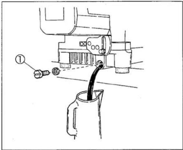
Fig. 4-5
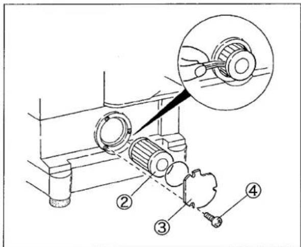
Fig. 4-6
5. Proper operation
5.1 Needle system
Proper needles for this machine are UY × 128GAS (UY128GAS).
Select proper needles in size according to the thickness and type of fabric.
5.2 Installing needles


WARNING
Before installing, ALWAYS turn the power switch OFF and check that the machine has already stopped.
(1) Loosen the screws① with a screwdriver. (Fig. 5-1)
(2) Remove the old needle with a pair of tweezers.
(3) Insert a new needle deep into a hole of the needle clamp ② so that the scarf of the needle is positioned to the right rear. (Fig. 5-2, 5-3)
(4) Tighten the screws① with the screwdriver.
NOTE
Tighten the screws ① with a tightening torque of 0.6N·m(6kgf·cm).
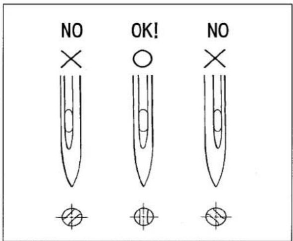
Fig. 5-2
| Japanese standard | 9 | 10 | 11 | 12 | 13 | 14 |
| Metric standard | 65 | 70 | 75 | 80 | 85 | 90 |
Table 3
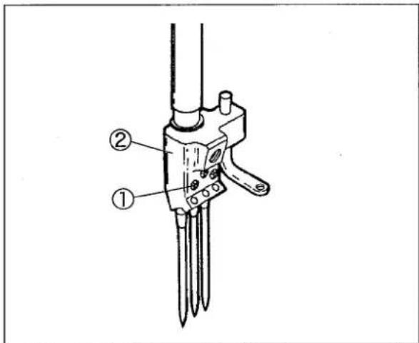
Fig. 5-1
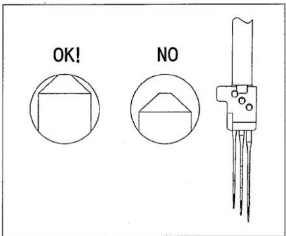
Fig. 5-3
5.3 Threading
☆ Needle thread
Pull out the threads until they come to the front of the needles. Then, cut off the knots before passing them through the needle eyes.
Thread correctly for the left needle which is in the inmost position of Fig. 5-4.
☆ When threaded, tie new threads with the preset threads for rethreading.
☆ When not threaded, thread correctly as shown in Fig. 5-4.
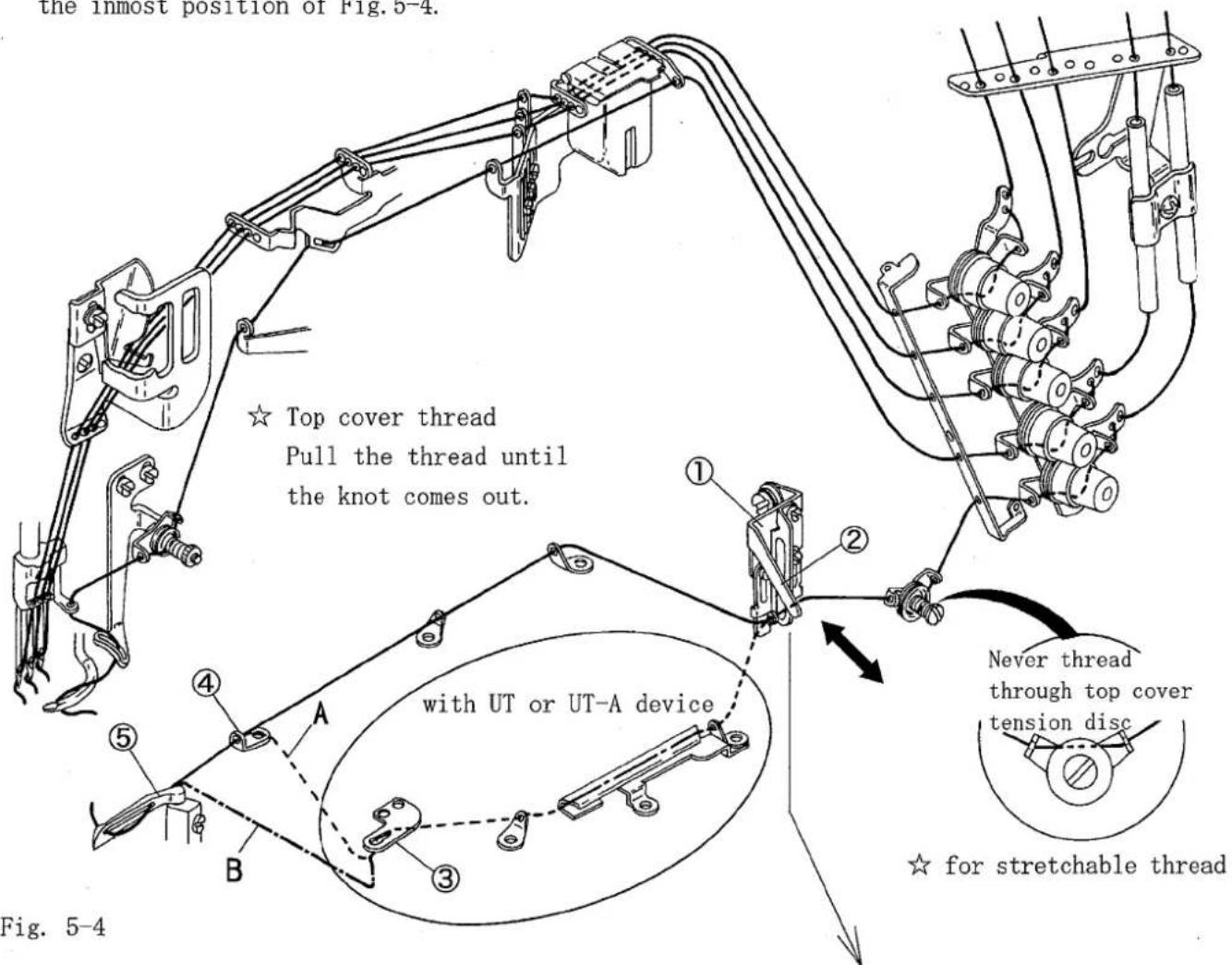
☆ Looper thread
Pull the thread until the knot comes out.
Then, cut off the knot.
Note: Threading for machines with UT or UT-A device
* For standard type thread, thread through the looper thread eyelet(left)④ via the looper thread pull-off③. (Thread A)
* For cotton thread or polyester thread, thread directly through the looper ⑤ via the looper thread pull-off ③. (Thread B)
Note: For easy threading, pull up the lever ② of the thread take-up eyelet holder ①.
After threading, press the lever② down to return the thread take-up eyelet holder① back to the original position.
5.4 Adjusting thread tension

Adjust the thread tension by the thread tension spring caps① according to the fabric type, thread type, seam width, stitch length, and other sewing conditions.
● To tighten the thread tension, turn the caps clockwise.
● To loosen the thread tension, turn the caps counterclockwise.
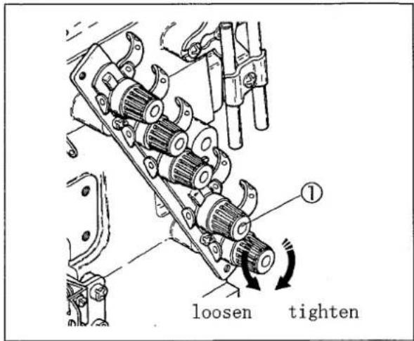
Fig. 5-5
5.5 Pressure of presser foot

Loosen the lock nut ② and turn the presser spring regulator ③ to adjust the pressure.
● To increase the pressure, turn it clockwise.
● To decrease the pressure, turn it counterclockwise.
Keep the pressure as low as possible for stable sewing performance.
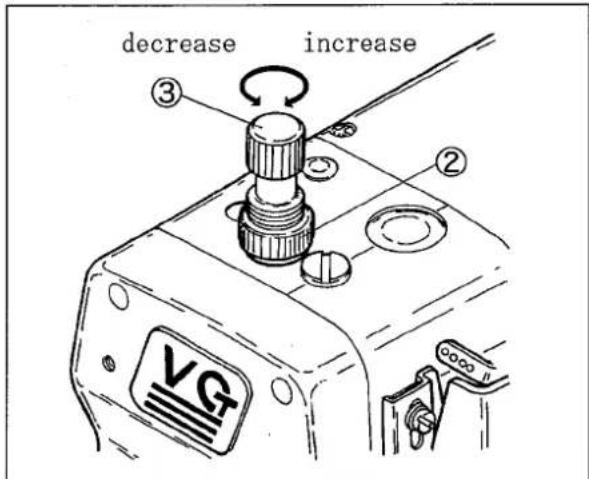
Fig. 5-6
5.6 Adjusting position of presser foot

WARNING
Before adjusting, ALWAYS turn the power switch OFF and check that the machine has already stopped.
Adjust left-and-right position of the needle holes of the presser foot.
Loosen the screw④. Move the front part of the presser foot right or left so that the needles can drop in the center of the needle drops respectively.
Then, tighten the screw④ securely.
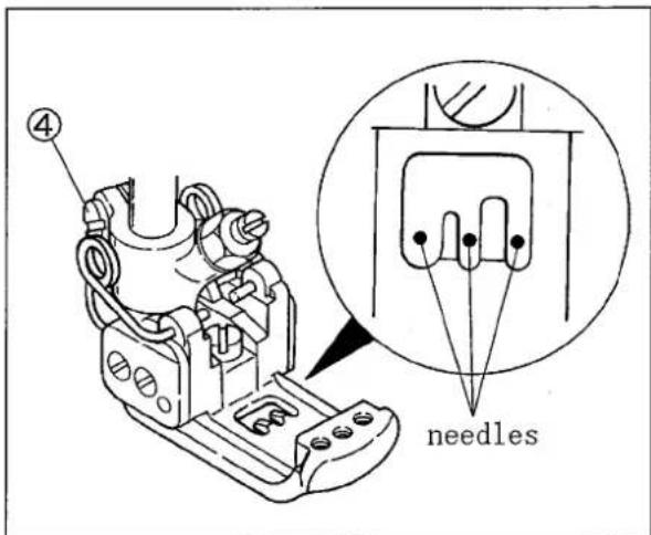
Fig. 5-7

WARNING
Before operating, ALWAYS turn the power switch OFF and check that the machine has already stopped.
5.7 Adjusting movement of differential feed dog

The differential ratio has been set from 1:1.1 to 1:1.5 at shipment. The ratio of 1:1.5 can be obtained when the stitch length is less than 3.6 mm.
(1) Loosen the lock nut ①. (2) Turn the adjusting screw ② to adjust the movement of the differential feed dog.
● To increase the movement for gathering sewing, turn it clockwise.
● To decrease the movement for stretching sewing, turn it counterclockwise.
(3) Tighten the lock nut① securely.
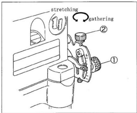
Fig. 5-8
![gathering [1:1.5] gathering [1:1.1]](/content/2026/05/990420/images/1af432fea6efd4f7cb06cf0624c4537b172d63221762a784a3b7e88ac066e0bf.jpg)
Fig. 5-9
5.8 Adjusting stitch length

Stitch length is adjustable from 1.4 to 3.6 mm. Table 4 shows the number of stitches per inch (25.4 mm) and every 30 mm.
The main feed lever stopper⑤ has been set to stop at maximum 3.6 mm by the screw⑥ at shipment.
※In case of VG2791, the main feed lever stopper⑤ has been set to stop at maximum 4.0 mm.
Adjusting procedure:
(1) Loosen the lock nut①.
(2) Fit the end of the main feed lever ④ to the desired position on the main feed graduations ③. Turn the main feed bar adjusting screw ② for adjustment.
● To make the stitch length smaller, turn it clockwise.
● To make the stitch length larger, turn it counterclockwise.
| Stitch length (mm) | Number of stitch (per 1 inch) | Number of stitch (per 30 mm) |
| 1.4 | 18 | 21 |
| 2.0 | 13 | 15 |
| 3.0 | 8.5 | 10 |
| 3.6 | 7 | 8 |
| 4.0 | 6.3 | 7.5 |
Note: the stitch length 4.0 mm is only for VG2791
Table 4
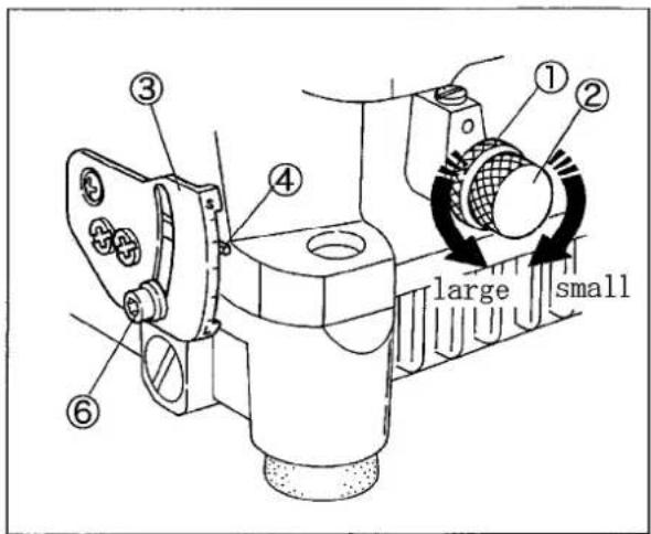
Fig. 5-10
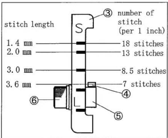
Fig. 5-11

WARNING
Before operating, ALWAYS turn the power switch OFF and check that the machine has already stopped.
5.9 Raising upper feed roller (for machines with puller mechanism)

Move the upper feed roller lifting lever② up and down to raise the upper feed roller① when want to pull out a fabric due to fabric jam.
Move up the upper feed roller lifting lever ② to make the upper feed roller ① stay at the up position.
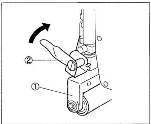
Fig. 5-12
5.10 Pressure of upper feed roller (for machines with puller mechanism)

Adjust the pressure of the upper feed roller as low as possible. At the same time, make sure that the rollers can feed a fabric smoothly.
Turn the adjusting screw③ to adjust it.
● To increase the pressure, turn it clockwise.
● To decrease the pressure, turn it counterclockwise.
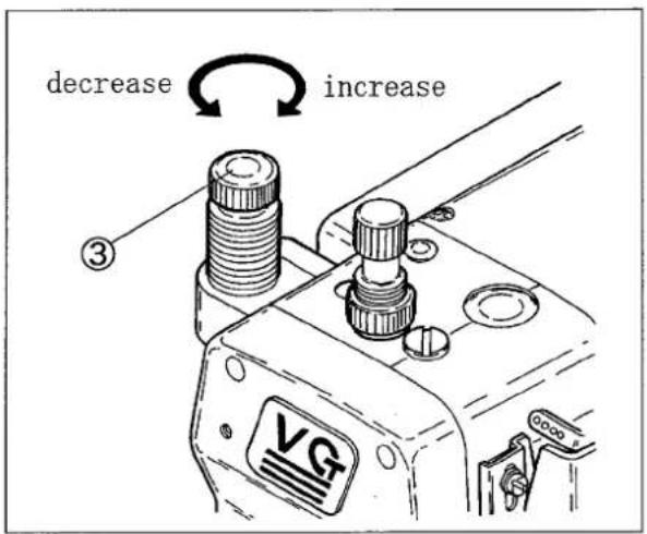
Fig. 5-13

WARNING
Before operating, ALWAYS turn the power switch OFF and check that the machine has already stopped.
5.11 SP device
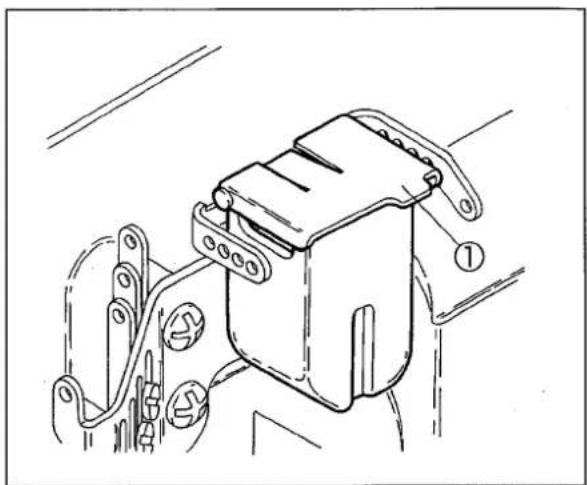
The SP device (needle thread oiling) has been equipped as standard to prevent thread breakage and skip stitch when running a machine at high speed or using synthetic thread and/or synthetic fabric.
Oil to be used: dimethyl silicon oil.
Open the lid① of SP container to check the oil level sometimes.

CAUTION
- When not using SP device, remove the felt. If not, it may cause irregular conditions during sewing performance.
- If silicone oil is sticked to the parts other than SP device, it can cause damage to the machine. Be sure to wipe it away.
natural_image
Technical line drawing of a mechanical component with no visible text or symbolsFig. 5-14
5.12 Cleaning the machine

Remove waste thread and dust from the machine at the end of work everyday.
Remove the seal plug ② from the back of the machine and clean the slots in the stitch plate, feed dog area, and oil filter screen area once a week.
NOTE
If the oil filter screen is clogged with dust, oil in the cylinder does not return to the oil reservoir. It can cause oil leakage.
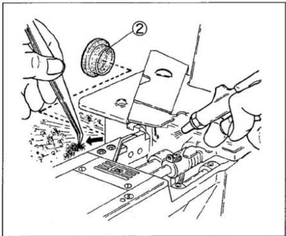
Fig. 5-15

WARNING
Before adjusting, ALWAYS turn the power switch OFF and check that the machine has already stopped.
6.1 Needle thread tension
Needle thread eyelet:
Align the center of the screws with the lines on the needle thread eyelet bracket④ as below.
Right needle thread eyelet①: top line Middle needle thread eyelet②: middle line Left needle thread eyelet③: bottom line
● To tighten the needle thread, raise the needle thread eyelet.
● To loosen the needle thread, lower it.
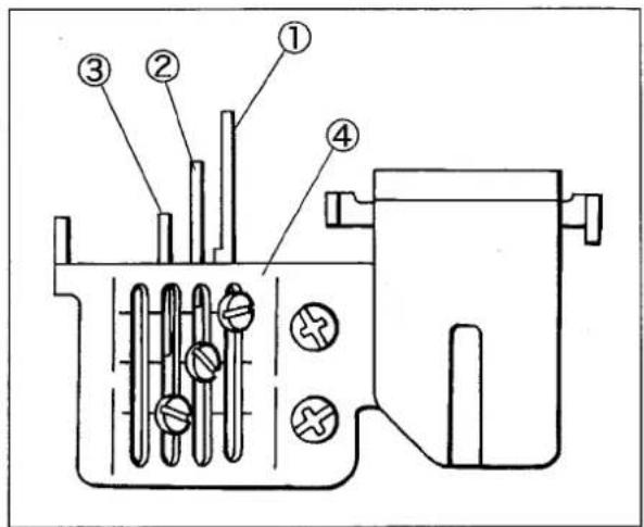
Fig. 6-1
Needle thread guide:
For standard position of needle thread guide, make the distance between the center of the eye in the needle thread take-up⑥ and the top of the needle thread guide ⑤ to 4.0 mm when the needle thread take-up⑥ is at the lowest point.
Make adjustment by loosening the screw⑦.
● To make the needle thread loop larger or when using stretchable thread, raise the needle thread guide ⑤.
● To make the loop smaller, lower it.
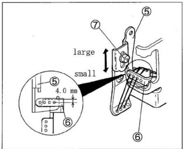
Fig. 6-2
6.2 Top cover thread tension
Align the center of the slot of the top cover thread eyelet (upper) ① with the center of the screw ② as the standard position.
Make adjustment by loosening the screws② and ③.
● To increase the feeding amount of the top cover thread, raise the top cover thread eyelet (upper) ①.
● To decrease the feeding amount of the top cover thread, lower the top cover thread eyelet (upper) ①.
NOTE
When using stretchable thread like woolly, make the top cover thread eyelet(upper) ^① a little higher than the standard.
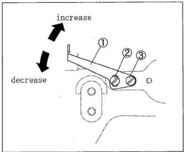
Fig. 6-3
6.3 Looper thread tension
Align the eyes of the thread take-up eyelets(left) ⑤ and (right)⑥ with the lines ④ on the thread take-up eyelet holder as standard.
Loosen the screws of both thread take-up eyelets to adjust them.
● To tighten the looper thread, raise both eye-lets.
● To loosen the looper thread, lower both eyelets.
NOTE
When using stretchable thread, move the thread take-up eyelets ⑤ and ⑥ to the lowest points. Do not thread through the top cover tension disc ⑦.
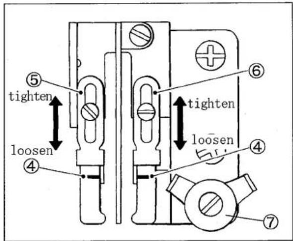
Fig. 6-4
6.4 Relation between needle and spreader
6.4.1 Spreader
(1) Loosen the screws ③ and ④ of the spreader holder. (Fig. 6-7)
(2) Make the clearance between the left needle and the hook② of the spreader① to 0.5 - 0.8 mm. (Fig. 6-5)
(3) Make the clearance between the center of the left needle and the hook② to 4.5 - 5.5 mm when the spreader① is at the extreme left. Then tighten the screw④ securely. (Fig. 6-5, 6-7)
(4) Make the height from the surface of the stitch plate to the bottom of the spreader to 8.5 - 9.5 mm. Then tighten the screw③ securely. (Fig. 6-6, 6-7)
NOTE
Adjust the height of the spreader so that the top cover thread can pass behind the right needle and be caught by the left needle within adjustable range based on the needle distance.
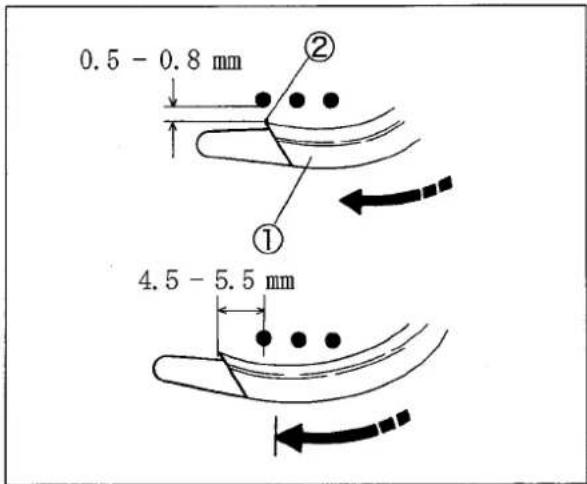
Fig. 6-5
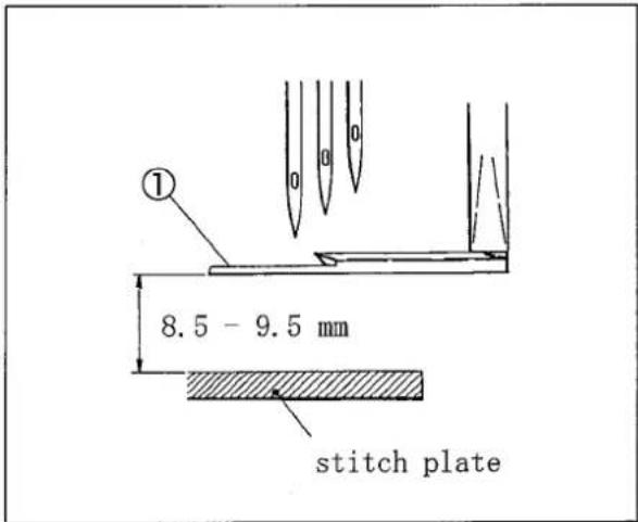
Fig. 6-6
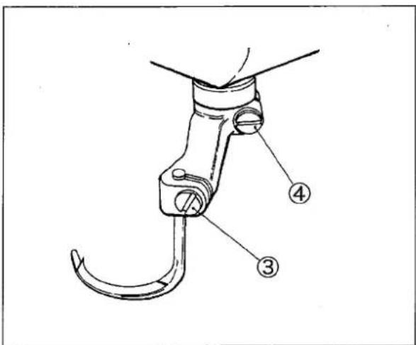
Fig. 6-7
6.4.2 Top cover thread guide
(1) Loosen the screws ② of the top cover thread guide ①. (Fig. 6-8)
(2) Make the clearance between the top surface of the spreader③ and the bottom of the top cover thread guide① to 0.5 mm. (Fig. 6-8)
(3) Let the center of the hook④ come to the center of slot on the top cover thread guide① when the spreader③ is at the extreme right. Then, tighten the screws② securely. (Fig. 6-8, 6-9)
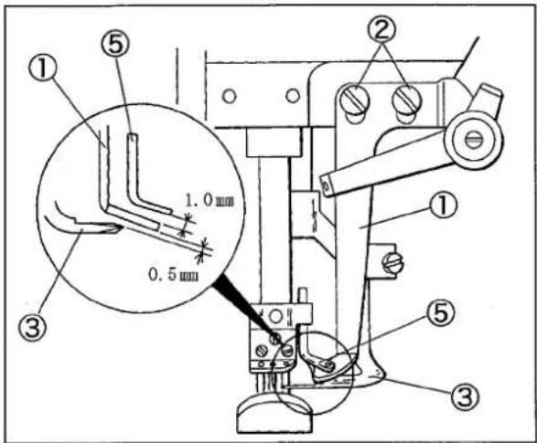
Fig. 6-8
6.4.3 Top cover thread eyelet
(1) Loosen the screw⑥ of the top cover thread eyelet⑤. (Fig. 6-9)
(2) Make the clearance between the top of the top cover thread guide① and the top cover thread eyelet ⑤ to 1.0 mm when the needle bar is at the lowest point. (Fig. 6-8)
(3) Set the eye of the top cover thread eyelet⑤ on the extending line from the slot of the top cover thread guide①. (Fig. 6-9)
(4) Tighten the screw⑥ securely. (Fig. 6-9)
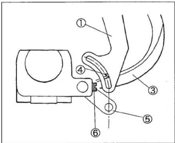
Fig. 6-9
6.5 Distance between needle and looper
The distance between the looper tip and the center of the right needle changes according to the needle distance when the needles are at the lowest points and the looper① is at the extreme right.
See Table 5 and loosen the screw② of the looper holder to make adjustment of the distance.
NOTE
The distance between the center of the needle bar and the looper ① tip is 6.0 mm even if the needle distance changes.
| needle distance (mark) | gauge mark | looper's distance |
| 3.2 mm (32) | A | 4.4 mm |
| 4.0 " (40) | B | 4.0 " |
| 4.8 " (48) | C | 3.6 " |
| 5.6 " (56) | D | 3.2 " |
| 6.4 " (64) | E | 2.8 " |
Table 5
The distance can be adjusted easily by using timing gauge (No. 95220).
The gauge is an extra part. Place an order with our agents or directly with us, if needed.
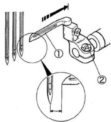
Fig. 6-10
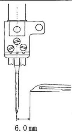
Fig. 6-11
6.6 Using timing gauge
The gauge has the marks (A, B, C, D, E) for each needle distance.
Move the looper to the extreme right. Keep fitting the right needle into the groove "V" according to the needle distance, and fit the looper tip to the gauge. Then, tighten the screw② securely.
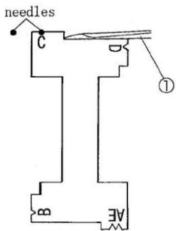
Fig. 6-12
6.7 Height of needle
(1) Install the needle into the left hole of the needle clamp.
(2) Make sure the looper has been inserted into the looper holder fully.
(3) Turn the handwheel until the looper tip meets the center of the left needle.
(4) Loosen the screw ① of the needle bar bracket and move the needle bar up and down. Make the looper tip pass the position that 0.8 - 1.3 mm above the top of the needle eye.
(5) Tighten the screw① securely. Make sure that the needle drops in the center of the needle hole on the stitch plate.
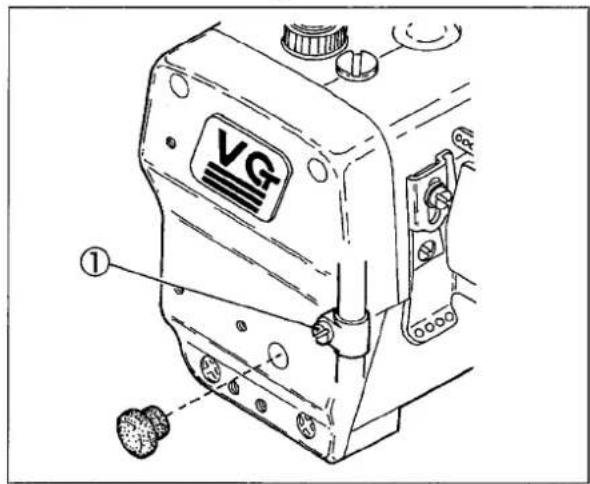
Fig. 6-14
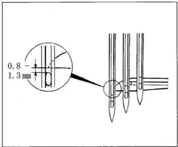
Fig. 6-13
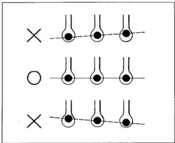
Fig. 6-15
6.8 Front-and-rear position of needle and looper
(1) Turn the handwheel until the looper tip④ meets the center of the left needle⑤.
(2) Loosen the screw③ and move the looper holder back or forth. Make the clearance between the back of the left needle⑤ and the looper tip to 0.2 - 0.3 mm. Then, tighten the screw③ securely.
NOTE
When tightening the screw③, front-and-rear position of the looper may be shifted. Recheck the position after tightening it.
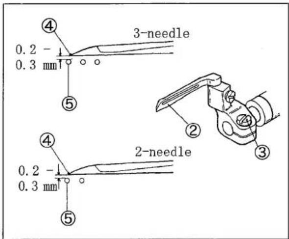
Fig. 6-16
6.9 Needle and needle guard (rear)
Height of needle guard(rear):
(1) Rotate the handwheel until the needle is raised up and the looper① tip comes to the center of the left needle②.
(2) Loosen the screw③.
(3) Adjust the needle guard(rear)④ so that the left needle② tip is 0 - 0.3 mm below the ridge line⑤.
(4) Tighten the screw③ slightly.
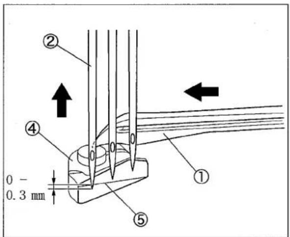
Fig. 6-17
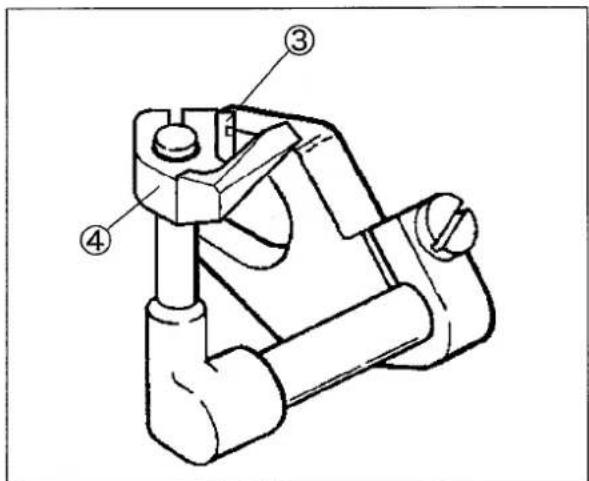
Fig. 6-18

WARNING
Before adjusting, ALWAYS turn the motor switch OFF and check that the motor has already stopped.
Front-and-rear position and angle between needle guard (rear) and needle:
Make adjustment by loosening the screws ① and ②. At the same time, meet the following conditions.
(1) When the looper③ moves from the right to the left, and the looper③ tip meets the right needle, let the needle guard(rear)④ push the right needle to make the clearance between them to 0 - 0.05 mm. (Fig. 6-19)
(2) When raising the needles, and the upper needle eye of the left needle ⑥ is aligned with the ridge line ⑤ on the needle guard (rear) ④, make the clearance between them to 0.2 - 0.5 mm. (Fig. 6-20)
(3) When the looper ③ tip comes to the center of the left needle ⑥, and the left needle ⑥ is pushed onto the needle guard (rear) ④, make the clearance between the looper ③ and the left needle ⑥ to about 0.1 mm. (Fig. 6-22)
After adjustment, tighten the screws① and ② securely.
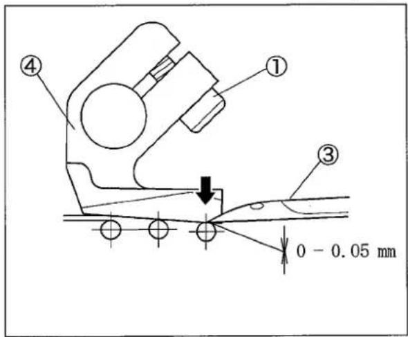
Fig. 6-19
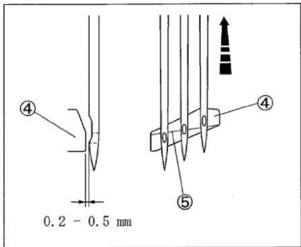
Fig. 6-20
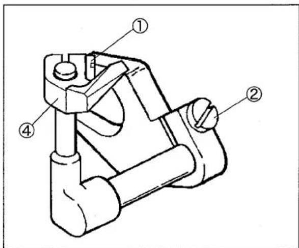
Fig. 6-21
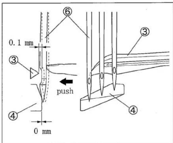
Fig. 6-22
6.10 Needle and needle guard (front)
(1) When the looper tip comes to the center of the right needle, loosen the screw②. Place the needle guard(front)① paralell to the line connecting the needles when viewing from the top. Tighten the screw②. (Fig. 6-23)
(2) Rotate the handwheel clockwise until the looper tip comes to the center of the left needle.
(3) Loosen the screw ② to adjust the needle guard (front) ① so that each needle tip is 2.5 - 3.0 mm below the corner on the needle guard(front) ①. (Fig. 6-24)
(4) Tighten the screw ②.
(5) Loosen the screws② and④. Make the clearance between the needle guard(front)① and the right needle or the left needle to 0.3 - 0.4 mm respectively. (Fig. 6-25)
(6) Tighten the screws② and ④ securely.
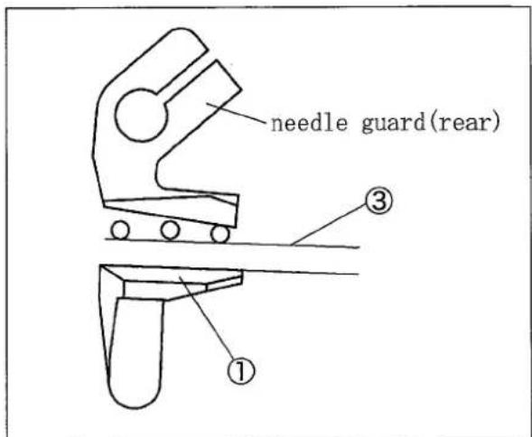
Fig. 6-23
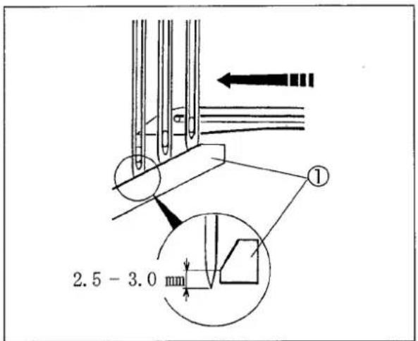
Fig. 6-24
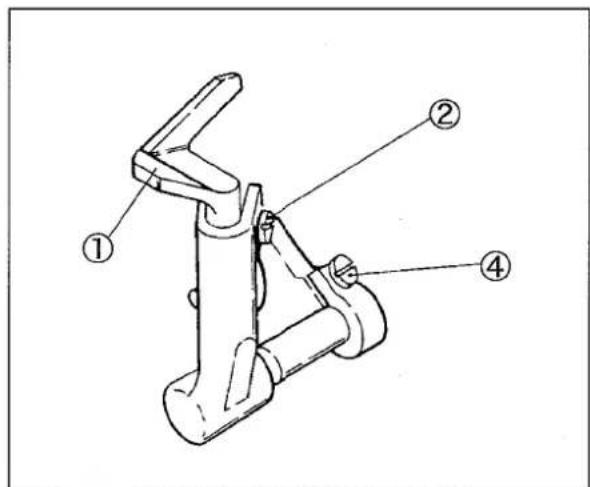
Fig. 6-25
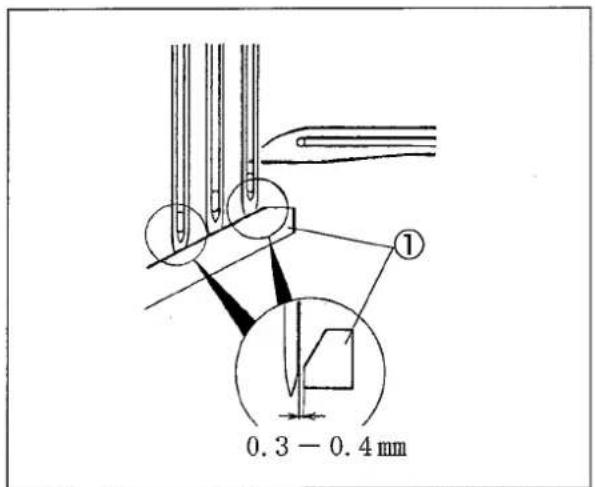
Fig. 6-26
WARNING
Before operating, ALWAYS turn the power switch OFF and check that the machine has already stopped.
6.11 Height of feed dog
Adjust the height from the top of the stitch plate to the tops of the differential feed dog① and the main feed dog② to 1.0 - 1.2 mm when the feed dogs are at the highest points. Also, make them parallel to the top of the stitch plate.
Loosen the screws③ and ④ to make adjustment.
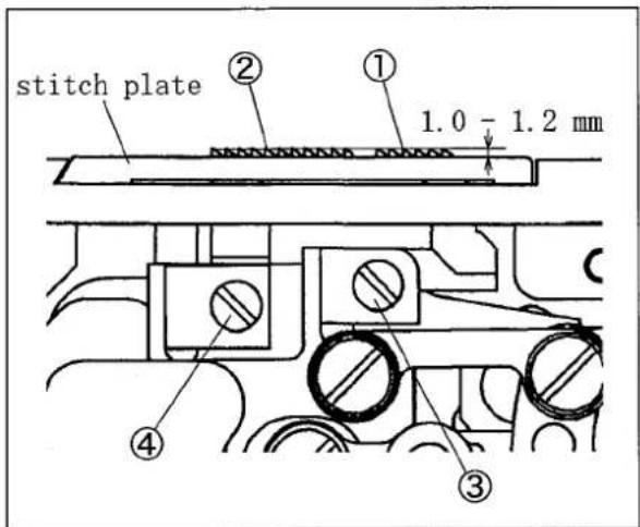
Fig. 6-27
6.12 Changing range of differential ratio
6.12.1 Differential ratio 1:1.1 - 1:2
(1) Adjust the stitch length to 2.3 mm or less.
(2) Loosen the screw of the differential feed lever stopper⑤ and set the stopper⑤ to the top.
(3) Loosen the lock nut ⑥ and turn the adjusting screw ⑦ clockwise. Raise the differential feed lever(right) ⑧ until it touches the differential feed lever stopper ⑤.
(4) Tighten the lock nut⑥ securely.
![gathering [1:2.0] gathering [1:1.5] gathering [1:1.1]](/content/2026/05/990420/images/f899c2aca85d49098dda1aabf2eb4fa0713e1eb1267e4cc076eaa4d7ed2d2ab0.jpg)
Fig. 6-28
NOTE
The following are the maximum stitch length of main feed dogs when using ratio of 1:2.
VG2790: 2.3 mm
VG2791:2.8mm
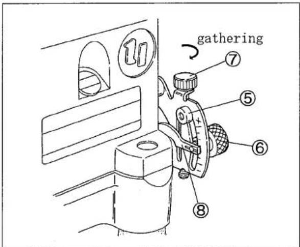
Fig. 6-29
WARNING
Before operating, ALWAYS turn the power switch OFF and check that the machine has already stopped.
6.12.2 Differential ratio 1:0.7 - 1:1.4
Removing covers:
(1) Remove the two screws, and then the stitch plate holder①.
(2) Remove the two screws, and then the front cover ②.
(3) Remove the two screws, and then the side cover ③.
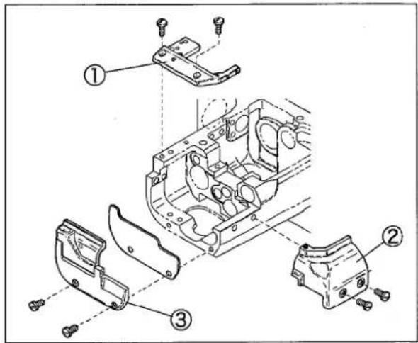
Fig. 6-30
Adjusting:
(1) Remove the screw⑤ of the differential feed bar connection④.
(2) Fix the differential feed bar connection④ to the hole⑥ with the screw⑤.
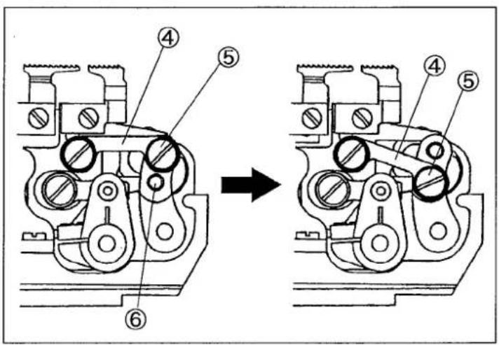
Fig. 6-31
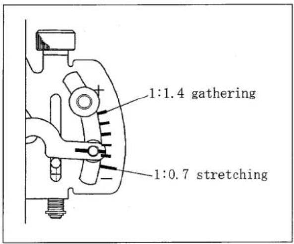
Fig. 6-32
WARNING
Before operating, ALWAYS turn the power switch OFF and check that the machine has already stopped.
Re-installing covers:
(1) Remove the liquid gasket attached to the machine frame and the front cover①.
(2) Apply the liquid gasket thinly on the shaded part □ on the machine frame.
(3) Re-install the stitch plate holder② with the screw③.
(4) Re-install the front cover① with the screws④ slightly.
(5) Tighten the screw⑤ of the stitch plate holder②.
(6) Tighten the screws④ of the front cover① securely.
Note: Make sure that the needles are in the center of the stitch plate, at the same time position the front cover.
(7) Re-install the side cover⑥ with the screws⑦.
(8) Wipe away the extra liquid gasket of the front cover①.
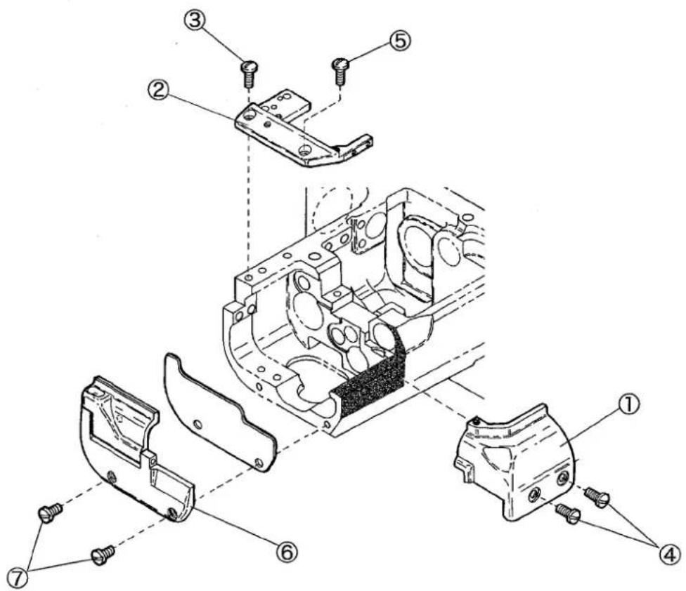
Fig. 6-33
6.13 Presser foot lift
The presser foot lift for the needle distance 5.6 mm is as follows:
- with spreader: 6.0 mm
- without spreader: 7.5 mm
(1) Loosen the lock nut①.
(2) Lower the lifter lever ② to make the clearance between the top of the stitch plate and the bottom of the presser foot to 6.0 mm (7.0 mm).
(3) Adjust the screw③ to make it touch the lifter lever② when the presser foot is raised up 6.0 mm (7.5 mm).
(4) Tighten the lock nut① securely.
(5) Loosen the screws⑤ of the collar④.
(6) Make the clearance between the presser bar bushing⑥ and the collar④ to 0.2 mm when the presser foot is raised up 6.0 mm (7.5 mm).
(7) Tighten the screws⑤ securely.

Fig. 6-34
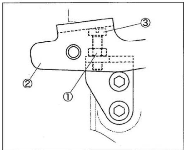
Fig. 6-35
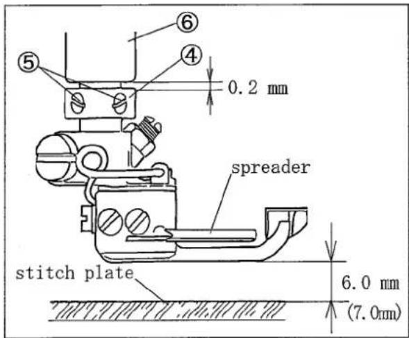
Fig. 6-36
6.14 Feeding amount of puller (for machines with puller mechanism)
(1) Remove the top cover seal plug①.
(2) Rotate the handwheel until the screw② of the upper feed roller regulator comes right above. Loosen the screw② with a hexagon socket screw-driver.
(3) Rotate the handwheel until the adjusting screw
③ comes right above. (Fig. 6-37)
(4) Turn the adjusting screw③ to adjust the feeding amount.
● To decrease the amount, turn it clockwise.
● To increase the amount, turn it counterclockwise.
(5) Tighten the screw② with a tightening torque of 2.5 N·m securely.
To make fine adjustment, loosen the nut ⑥ of the upper feed roller lever rod ⑤ for the upper feed roller lever ④. And move the screw ⑥ up or down to adjust it.
● To decrease the amount, move it up.
● To increase the amount, move it down.
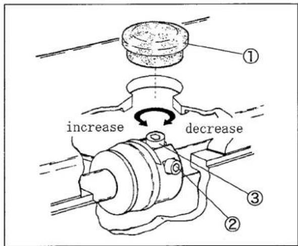
Fig. 6-37
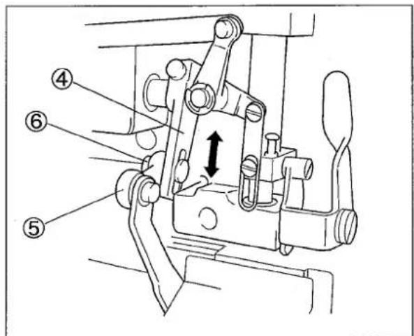
Fig. 6-38
6.15 Pressure of clutch tension spring (for machines with puller mechanism)
(1) Loosen two screws ⑧ to tighten the collar ⑦ slightly.
(2) Turn the adjusting screw ^⑨ to adjust the pressure of the clutch tension spring ^⑩ .
● To increase the pressure, turn it clockwise.
● To decrease the pressure, turn it counterclockwise.
For the pressure of clutch tension spring ^⑩ , adjust it to the level that the clutch tension spring ^⑩ rotates smoothly when pressed by a finger lightly.
(3) Tighten two screws⑧ securely.
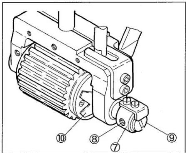
Fig. 6-39
7. Specifications
| Model | VG2790 class |
| Description | High speed unique cylinder bed 3-needle chain stitch machine |
| Dimensions | 442 mm (L) ×220 mm (W) ×405 mm (H) |
| Circumference of Cylinder | 280 mm |
| Weight | 40.5 kg |
| Stitch Type | ISO 406, 407, 602, 605 |
| Application | Covering seam on knitted fabric |
| Sewing Speed | Maximum speed: 6500 rpm (during intermittent operation)(with puller: 5000 rpm) |
| Stitch Length | 1.4 - 3.6 mmNumber of stitches 7 - 18 stitches per inch(25.4 mm)8 - 21 stitches per 30 mm |
| Needle System | UY×128GAS No. 65 - No. 90 (standard: No. 70) |
| Needle Distance | 3-needle: 4.8 mm, 5.6 mm, 6.4 mm(2-neelde: 3.2 mm, 4.0 mm) |
| Needle Stroke | 31 mm |
| Presser Foot Lift | For 5.6 mm of needle distance with spreader: 6.0 mm, without spreader: 7.5 mm |
| Feed Regulation | By adjusting screw (available for micro adjustment) |
| Differential Ratio | Standard: 1 : 1.1 - 1 : 1.51 : 1.1 - 1 : 2 (stitch length is 2.3 mm or less in max. normal differential)1 : 0.7 - 1 : 1.4 (adjustable by changing position of feed bar connection) |
| Differential Feed Regulation | Micro adjustment by adjusterAdjustable by moving external lever even during operation |
| Lubrication | Lubrication automatically by trochoid-shaped pump |
| Lubricating Oil | YAMATO SF OIL No. 28 |
| Capacity of Oil Reservoir | 800 cc |
| Installation | Table top type or semi-submerged type |
Ljamato
ヤマトミシン製造株式会社
YAMATO SEWING MACHINE MFG. CO., LTD.
4-4-12, NISHITENMA, KITA-KU, OSAKA, JAPAN
TEL:81-6-6364-1321 FAX:81-6-6364-1307
- Name of each part
- Installation
- Sewing speed and rotating direction of pulley 10
- Lubrication
- Proper operation
- Adjustment 20
- Specifications 34
- Attention
- To ensure safe use
- 1-1 Application and purpose
- 1-2 Before use
- 1-3 Working environment
- 1-4 Unpacking and transportation
- Installation and preparation
- 2-1 Instruction and training
- 2-2 Sewing table and motor
- 2-3 Wiring
- 2-4 Before operation
- 2-5 During operation
- 2-6 Removal
- Maintenance, inspection, and repair
- Caution signs and alert pictorial markings
- 4-1 Meanings of caution signs
- 4-2 Alert pictorial markings
- Warning labels on sewing machines
- Table cutting diagram
- Table top type (Type A: standard)
- Table top type (Type B)
- Semi-submerged type
- Semi-submerged type with compact motor
- Table top type
- Semi-submerged type
- Motor, belt and pulley
- CAUTION
- Servomotor:
- Belt
- Hanging belt
- WARNING
- Belt cover
- Eye guard and finger guard
- Sewing speed and rotating direction of pulley
- Lubricating oil
- Lubricating
- Changing oil
- Timing:
- Procedure:
- NOTE
- Checking and replacing oil filter
- Needle system
- Installing needles
- Threading
- ☆ Needle thread
- ☆ Looper thread
- Adjusting thread tension
- Pressure of presser foot
- Adjusting position of presser foot
- Adjusting movement of differential feed dog
- Adjusting stitch length
- Adjusting procedure:
- Raising upper feed roller (for machines with puller mechanism)
- Pressure of upper feed roller (for machines with puller mechanism)
- SP device
- Cleaning the machine
- Needle thread tension
- Needle thread eyelet:
- Needle thread guide:
- Top cover thread tension
- Looper thread tension
- Relation between needle and spreader
- Spreader
- Top cover thread guide
- Top cover thread eyelet
- Distance between needle and looper
- Using timing gauge
- Height of needle
- Front-and-rear position of needle and looper
- Needle and needle guard (rear)
- Height of needle guard(rear):
- Front-and-rear position and angle between needle guard (rear) and needle:
- Needle and needle guard (front)
- Height of feed dog
- Changing range of differential ratio
- Differential ratio 1:1.1 - 1:2
- Differential ratio 1:0.7 - 1:1.4
- Removing covers:
- Adjusting:
- Re-installing covers:
- Presser foot lift
- Feeding amount of puller (for machines with puller mechanism)
- Pressure of clutch tension spring (for machines with puller mechanism)
- Specifications
- Ljamato
- ヤマトミシン製造株式会社
- YAMATO SEWING MACHINE MFG. CO., LTD.
Brand : Yamato
Model : VG2790
Category : Sewing machine