MG2002PC - Sewing machine Yamato - Free user manual and instructions
Find the device manual for free MG2002PC Yamato in PDF.


| Product Type | Industrial Sewing Machine |
| Brand | Yamato |
| Model | MG2002PC |
| Number of Needles | Up to 4 (typically 1 or 2 installed) |
| Needle Width Configurations | A,C: 31.8 mm; B,D: 34.9 mm; A,B: 6.35 mm; C,D: 9.45 mm; A,D: 41.25 mm; B,C: 25.45 mm |
| Feed Dog Height | 1.4 – 1.6 mm from stitch plate at highest point |
| Roller Lifting Amount | 5 mm standard, adjustable |
| Air Pressure Requirement | 0.4 MPa |
| Motor Compatibility | Mitsubishi FMF or GMF series |
| Included Devices | Presser foot lifter (FL10), Roller lifter (APL10), Solenoid valve |
| Threading | Needle thread and looper thread, with tying method for rethreading |
| Usage | Waist band sewing (straight or curved) and similar applications |
| Weight | Approx. 80 kg (estimation) |
| Dimensions (L x W x H) | Approx. 1000 x 500 x 400 mm (estimation) |
| Power Supply | 200 V AC, 3-phase (typical industrial) |
| Safety Features | Motor switch must be off before needle installation or threading |
| Maintenance | Clean feed dog after use, check needle-looper clearance |
Frequently Asked Questions - MG2002PC Yamato
User questions about MG2002PC Yamato
0 question about this device. Answer the ones you know or ask your own.
Ask a new question about this device
Download the instructions for your Sewing machine in PDF format for free! Find your manual MG2002PC - Yamato and take your electronic device back in hand. On this page are published all the documents necessary for the use of your device. MG2002PC by Yamato.
USER MANUAL MG2002PC Yamato
natural_image
Technical line drawing of a Yamato sewing machine (no text or symbols present)This instruction manual includes adjustments differed from MG2000 model.
Before using your MG2002PC model, please read both of the instruction manuals and understand the contents well. After reading the instruction manuals, please keep them in a location where it is easily accessible to the operator.
Contents
1. Installation 1
1.1 Installing presser foot lifter device (with FL10 device)
1.2 Installing roller lifter cylinder (with APL10 device) 1
1.3 Installing solenoid valve 2
1.4 Wiring and Air piping 2
1.4.1 Wiring 2
1.4.2 Air piping 2
1.5 Installing folder bracket 3
1.6 Program for motor 4
2. Proper operation 5

2.1 Installing needles 5
2.2 Threading 6
2.3 Procedure 7
3. Adjustment 8
3.1 Height of feed dog 8
3.2 Adjusting tape guide of presser foot and fabric guide 9
3.3 Installing folder 9
3.4 Movement of roller (puller's feed amount) 10
3.5 Height of roller 11
3.6 Lifting amount of roller 11
3.7 Adjusting roller 12
3.7.1 For straight band 12
3.7.2 For curved band 13
3.7.3 Attention for setting roller 14
1.1 Installing presser foot lifter device (with FL10 device)
- Loosen the lock nut ② of the cylinder rod chip ① fully, and then tighten the cylinder rod chip ① fully.
- Install the air cylinder, C. set③ to the back of the sewing machine with the screws ④ and washers ⑤ (2 pcs. for each) as Fig.1.
- Install the solenoid valve. (Refer to [1.3 Installing solenoid valve])
- Connect the pipe to the air cylinder, C. set③. (Refer to 「1.4 Wiring and air piping」)
- Turn the motor switch ON.
- Toe down the pedal and lift the presser foot up.
- Adjust the cylinder rod chip① as below
(1) While pressing down the lifter lever ⑥ by hand, turn the cylinder rod chip ①, and lower the lifter lever ⑥ to where it touches the lifter lever stopper ⑦.
(2) Tighten the nut ② and fix the cylinder rod chip ①.
- Lower the presser foot and make sure the clearance between the lever ⑥ and the chip ① is enough. If there is no clearance, loosen the nut ② and the chip ① a little to make one.
WARNING
After installation, turn the motor switch OFF.

Fig. 1

Fig. 2
1.2 Installing roller lifter cylinder (with APL10 device)
- Remove the screws(4 pcs.) from the rear cover⑧.
- Install the roller lifter cylinder⑧ with the screws ⑩ and washers⑪.
- Connect the feed roller lifter link⑫ and the puller link joint ⑬ with the screw⑭.
- Connect the air pipes. (Refer to 「1.4 Wiring and air piping」)

Fig. 3
1. Installation
1.3 Installing solenoid valve
- Loosen the screws ①(2 pcs.) from the back of the sewing machine.
- Insert the solenoid valve support ② into the screws ①, and tighten them ①.
1.4 Wiring and air piping
1.4.1 Wiring
○Set the knee switch to the bottom of the table.
○Connect the connectors③ from intermediate cable to the solenoid valve④ by the same number.
○Connect the connectors⑤ from intermediate cable to the cord connectors from the switch and sensor.
○ Connect each connector from intermediate cable with the one on the control box that is the same in color and shape.

Fig. 4
1.4.2 Air piping
Install the air regulator to the bottom of the table. Connect the air pipes as the figure. Set the air regulator to 0.4MPa.

1.5 Installing folder bracket
-
Fix the folder bracket① with the screws② and place it parallel with the top of the stitch plate.
-
Fix the folder bracket③ with the screws④ and place it vertical to the top of the stitch plate. (Set it a little higher than the stitch plate.)
When installing folder
Adjust the up-and-down direction by the screws④.
Adjust the right-and-left direction by the screws⑤.
-
Set the folder to folder bracket⑥ with the screws⑦.
-
Make the clearance between the upper surface of supplementary cover ⑧ and the folder bottom as less as possible.
Make sure the folder bracket③ falls forward smoothly. ( Make adjustment by the screws④.)
Note) The folder need to be prepared by customer.

Fig. 6
1.6 Program for motor
In case of using roller lifer device(APL10 device), refer to the instruction manual for motor and install the program as the following.
For Mitsubishi motor FMF or GMF series
| C mode (↓ + C) | S mode (↓ + B + D) | ||
| Function | Set value | Function | Set value |
| IA | F | SQS | Go |
| IB | I01 | NS1 | oN |
| IH | I02 | NE1 | oN |
| IM | UF | S1S | IN |
| oM | oT2 | K11 | how many stitches the sewing machine |
| A1 | I01 | sews before the puller rise, after detecting the fabric | |
| N1 | oT2 | ||
| N2 | FU | K12 | how many stitches the sewing machine |
| IC | I06 | sews after the puller rise and before the puller lowers | |
| IN | I01 | ||
| oN | KS1 | ||
| ICL | oM | ||
i Supplement
Change the set value of K11 and K12 when changing stitch length.
WARNING
ALWAYS turn the motor switch OFF and check that the motor has been stopped, before installing needles. If not, it may cause injury.
2.1 Installing needles
- Loosen the screws② of the needle① with a screwdriver.
- Remove the old needle with a pair of tweezers.
- Insert a new needle into the needle clamp③ as far as it goes with facing it scarf to the left.
- Tighten the screws② of the needle①.
Attention
Be sure to check the “clearance between the needle and the looper” and “clearance between the needle and needle guard” after needle changing.
(Refer to the instruction manual for MG2000 on page 19.)
i Supplement
One or two needles are installed for using, even though four needles can be installed.
According to the installing position of the needles, the width of the needles will be as the following.
| A,C | 31.8mm |
| B,D | 34.9mm |
| A,B | 6.35mm |
| C,D | 9.45mm |
| A,D | 41.25mm |
| B,C | 25.45mm |

Fig. 7
2.2 Threading


WARNING
ALWAYS turn the motor switch OFF and check that the motor has already stopped, before threading.
Improper threading can cause thread breakage, skip stitch, and uneven stitch.
When not threaded, thread correctly as shown in Fig. 8,9. When threaded, rethread by tying new threads to the preset threads.
Needle thread
- Pull the new threads until the knots come to the front of the needle.
- Cut off the knots and pass the threads through the needle eyes.
Looper thread
Change the threading for looper according to the installing position of the needles. The threading of needle thread take-up ① and looper thread eyelet(left) ② has been shown in Fig.9.
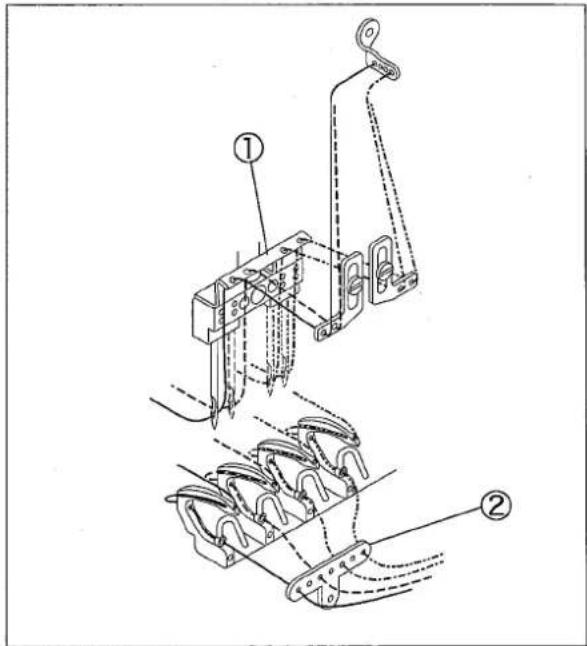
Fig. 9

2.3 Procedure

In both cases of with FL10 device and APL10 device
- Heel back the pedal.
The presser foot and the puller will be raised.
- Release the pedal to neutral.
The presser foot and the puller will be lowered.
- Toe down the pedal, start sewing.
When the fabric comes to the front of the puller, puller rises up, and when fabric reaches puller, puller lowers. (Adjust it by the program for motor.)
Others
○Press the knee switch.
Only the presser foot rises up.
However, when the sewing machine starts running,
the presser foot falls down.
○Press the manual switch.
The puller rises up.

Fig. 10
3. Adjustment
3.1 Height of feed dog
Adjust the height of the feed dog①(the third rows on the left) to 1.4-1.6 mm from the top of the stitch plate when the feed dog is at the highest point.
Adjusting
- Remove the needle, the presser foot and the stitch plate holder.
- Loosen the adjusting screw②, the nut③ and the screw ④ for the feed dog①.
- Adjust the height of the feed dog①, and tighten the screw④.
- Tighten the screw ② until it touches the feed bar lightly, then fix it with the nut ③.
- Re-install the stitch plate holder, the presser foot, and the needles.
※ After this adjustment, the height of the feed dog① will be automatically decided by the screw②, even though the feed dog is removed for cleaning etc.

Fig. 11

Fig. 12

Fig. 13
3.2 Adjusting the tape guide of presser foot and fabric guide
- Tape guide(left)② guides the upper part of the tape ①. Make adjustment by letting the tape guide(left)② touch the tape lightly and tighten the screw③.
- Fabric guide ⑤ guides the lower part④ of the tape. Make adjustment by letting the fabric guide⑤ touches the tape lightly and tighten the screw⑥.

Fig. 14
3.3 Installing folder
Front-and-rear position
Make the distance between the presser foot ⑦ and the folder ⑧ to about 10mm as shown in figure.
Right-and-left position
Make the left side of folder⑧ parallel with the direction of the tape sending and match it to the tape guide ② of the presser foot as figure.
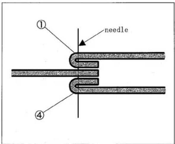
Fig. 15

Fig. 16
3.4 Movement of roller (puller's feeding amount)
Adjust the movement of the upper feed roller according to type of material and the sewing condition.
- Loosen the nut①, place the upper feed roller lever rod② is middle of the slot on the upper feed roller lever ③ as standard. Tighten the nut① after setting.
-
Adjust the position of upper feed roller lever rod ②, when the feeding amount of roller is insufficient.
-
Move it in the U direction…The feeding amount decreases.
- Moving it in the D direction…The feeding amount increases.

Fig. 17
3.5 Height of roller
- Loosen the screw② of the collar①.
- Let the roller touch the roller lower plate(right)④ and (left)⑤ firmly, when the roller is lowered.
- Fix the collar① with the screw② to make the clearance between the collar① and the bracket⑥ to 0.

Fig. 18
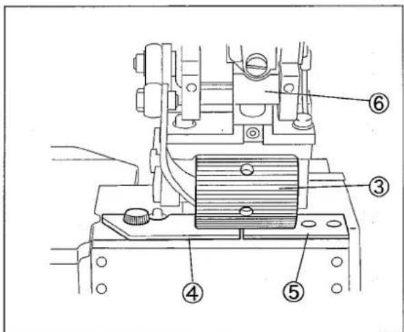
Fig. 19
3.6 Lifting amount of roller
Make the lifting amount of the roller to 5mm as standard.
Make adjustment by loosening the screw⑧ for the collar⑦ of feed roller lifter cylinder, and move the collar right and left.
- Moving it in the I direction…The lifting amount decreases.
- Moving it in the J direction…The lifting amount increases.

Fig. 20
3.7 Adjusting roller
Adjustment for roller will be different according to that the waist band is straight(it will be called as "straight band" in the following) or curved (it will be called as "curved band" in the following) when sewing a waist band for such as jeans onto the body part.
3.7.1 For straight band
In case of switching to straight band from curved band
- Loosen the screw② of upper feed roller lever①.
- Loosen the two screws④ of upper roller yoke(lower) ③.
- Rotate upper roller yoke(lower)③ fully counterclockwise in view of above, and tighten the screws④. (Fig. 22)
- Loosen the screw ⑥, put the roller lower plate(right)⑤ upside down and change the direction. Fix it with the screw⑥ as figure.
- Tighten the screw② to adjust the right-and-left position of upper feed roller lever①. (Refer to 「3.7.3 Attention for setting roller」.)
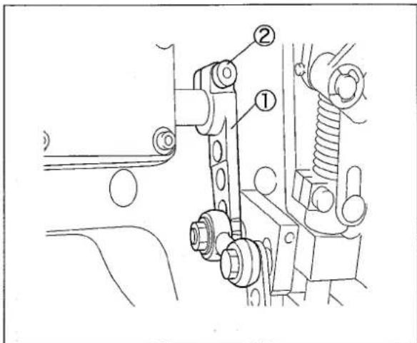
Fig. 21

Fig. 22
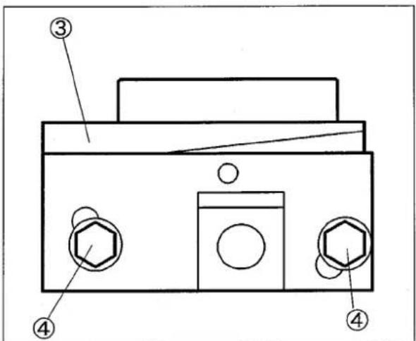
Fig. 23
3.7.2 For curved band
In case of switching to curved band from straight band
It is possible to sew the curved band well by doing only 1 of the following procedure. In that case, the procedure after 2 will not be necessary.
- Loosen the screw④ of the roller lower plate(right)③ turn the roller lower plate upside down and place it with an angle as shown in the figure, because of not using. (Fig.24) Do test sewing and decide if the adjustments after procedure 2 are necessary.
- Loosen the screw ② of upper feed roller lever ①. (Fig. 21)
- Loosen the two screws ⑥ of upper feed roller yoke (lower) ⑤. (Fig. 25)
- Rotate the upper roller yoke(lower)⑤ clockwise in view of above, and tighten the screw⑥(2pcs.).
- Tighten the screw② to adjust the right-and-left position of upper feed roller lever①.(Fig.21) (Refer to「3.7.3 Attention for setting roller」.)
i Supplement
Upper feed roller yoke(lower)③ need to be turned according to the curved condition of waist band. When upper feed roller yoke(lower)③ is overturned, the sewing may not be carried out properly.

Fig. 24

Fig. 25
3. Adjustment
3.7.3 Attention for setting roller
-
Adjust the right-and-left position of the upper feed roller lever① to make upper feed roller lever①, upper feed roller lever rod② and clutch driving lever (right)③ move smoothly.
-
Tighten the screw ④ lightly, adjust the clearance between the machine arm and the upper feed roller lever ① to about 5mm by rotating the hand wheel. Then tighten the screw ④ firmly.
● Switching to curved band from straight band
Move the upper feed roller lever in the direction "A".
● Switching to straight band from curved band
Move the upper feed roller lever in the direction "B".

Fig. 26
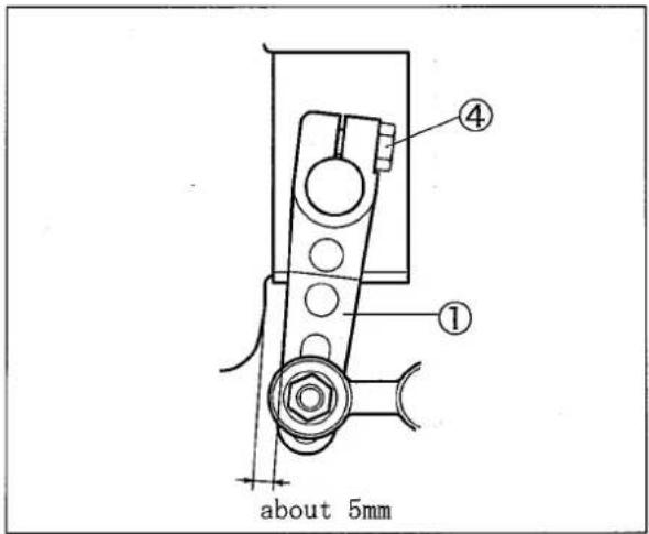
Fig. 27
1jamato
ヤマトミシン製造株式会社
YAMATO SEWING MACHINE MFG. CO., LTD.
4-4-12, NISHITENMA, KITA-KU, OSAKA, JAPAN
TEL:81-6-6364-1321 FAX:81-6-6364-1307
- Contents
- Installation 1
- Proper operation 5
- Adjustment 8
- Installing presser foot lifter device (with FL10 device)
- WARNING
- Installing roller lifter cylinder (with APL10 device)
- Installation
- Installing solenoid valve
- Wiring and air piping
- Wiring
- Air piping
- Installing folder bracket
- Program for motor
- i Supplement
- Installing needles
- Attention
- Threading
- Needle thread
- Looper thread
- Procedure
- Adjustment
- Height of feed dog
- Adjusting
- Adjusting the tape guide of presser foot and fabric guide
- Installing folder
- Front-and-rear position
- Right-and-left position
- Movement of roller (puller's feeding amount)
- Height of roller
- Lifting amount of roller
- Adjusting roller
- For straight band
- In case of switching to straight band from curved band
- For curved band
- In case of switching to curved band from straight band
- Attention for setting roller
- 1jamato
- ヤマトミシン製造株式会社
- YAMATO SEWING MACHINE MFG. CO., LTD.
Brand : Yamato
Model : MG2002PC
Category : Sewing machine