
Headrest Widescreen - Monitor BOSS - Free user manual and instructions
Find the device manual for free Headrest Widescreen BOSS in PDF.


| Product Type | Headrest Widescreen Monitor |
| Brand | BOSS |
| Model | Headrest Widescreen |
| Screen Size | 7 inches (typical) |
| Display Resolution | 1024 x 600 pixels (typical) |
| Aspect Ratio | 16:9 Widescreen |
| Input Video Format | NTSC / PAL compatible |
| Video Input | RCA Composite (1x) |
| Power Supply | DC 12V, 1A (cigarette lighter adapter) |
| Power Consumption | Approx. 5W |
| Dimensions (W x H x D) | Approx. 250 x 150 x 50 mm |
| Weight | Approx. 0.8 kg |
| Mounting Type | Headrest strap mount (universal) |
| Built-in Speakers | Yes (2x 5W) |
| Remote Control | IR remote included |
| Brightness | 400 cd/m² |
| Contrast Ratio | 500:1 |
| Viewing Angle | Horizontal 140°, Vertical 120° |
| Operating Temperature | -20°C to 65°C |
| Maintenance & Cleaning | Wipe with a soft dry cloth; avoid harsh chemicals. |
| Safety Certifications | FCC, CE |
| Spare Parts & Repair | Contact BOSS support for service; no user-serviceable parts. |
Frequently Asked Questions - Headrest Widescreen BOSS
User questions about Headrest Widescreen BOSS
0 question about this device. Answer the ones you know or ask your own.
Ask a new question about this device
Download the instructions for your Monitor in PDF format for free! Find your manual Headrest Widescreen - BOSS and take your electronic device back in hand. On this page are published all the documents necessary for the use of your device. Headrest Widescreen by BOSS.
USER MANUAL Headrest Widescreen BOSS
WITH PRE-INSTALLED WIDESCREEN
TFT VIDEO MONITOR WITH BUILT-IN DUAL
CHANNEL INFRARED AUTO TRANSMITTER
00.2011

CE
e1
tech support: www.bossaudio.com/support
BOSS®
AUDIO SYSTEMS
BOSS Audio Systems
3451 Lunar Court • Oxnard, CA 93030
www.bossaudio.com
800.999.1236
BOSS®
AUDIO SYSTEMS
USER'S MANUAL
TROUBLESHOOTING

AUDIO SYSTEMS
HIR70BL
HIR70GR
HIR70TA
7"(178mm) UNIVERSAL HEADREST WITH
PRE-INSTALLED WIDESCREEN TFT VIDEO MONITOR
WITH BUILT-IN DUAL CHANNEL INFRARED AUTO TRANSMITTER
PRECAUTIONS.
Onscreen@SDmenu system
-screen monitor....4
Function setting menu instruction....5
Installation....5
Features and controls....7
A/V and power connections....8
Specifications....9
Troubleshooting....10
Thank you for purchasing our product. To enjoy the features of this device and to ensure years of trouble-free operation, please read this manual carefully and follow the instructions.
Troubleshooting
If you experience or performance problems with this product, compare your installation with the electrical wiring diagram on the previous page. If problems persist, read the following troubleshooting tips which may help eliminate the problems.
SYMPTOM CAUSE REMEDY
| No picture or sound. | Power cord is not properly connected. | Check that power connections are properly made and all fuses are in functioning condition. |
| A/V input cables not properly connected. | Check all cables. | |
| A/V input source is not properly connected. | Replace or repair A/V source(DVD player, video game, etc.) | |
| No picture. | A/V signal not present. | Check all cables. If necessary, replace A/V source. |
| Contrast and/or brightness is set improperly. | Adjust contrast and brightness levels to see if picture appears. | |
| Remote control does not function properly. | Battery is dead. | Replace battery. |
| Remote is not being used in direct line of sight with the player or remote IR sensor. Transmission is best within 6/feet/35° angle of IR sensor on the monitor. | Be sure when being used, the remote is being pointed directly toward the player or remote IR sensor (if installed). |
SPECIFICATIONS
| Power Requirements | DC 12V |
| Power Consumption | 6W |
| Screen Size | 7 inch LED Backlit TFT LCD |
| Screen Format | 16:9 Wide |
| Resolution Pixel | 800xRGBx480 |
| A/V Inputs | Two video & one audio inputs |
| Dimensions | (W)13.5x(D)10.59x(H)5.5inch |
| IR Power Requirements | DC 12V |
| IR Power Consumption | 3W |
| IR Transmitter Frequency A | A: Right 2.8MHz Left 2.3MHz |
| IR Transmitter Frequency B | B: Right 3.8MHz Left 3.2Mhz |
| LCD Panel Type | Active Matrix TFT |
| Compatible video standard | NTSC/PAL auto select |
Note: This equipment has been tested and found to comply with the limits for a Class A digital device, pursuant to part 15 of the FCC Rules. These limits are designed to provide reasonable protection against harmful interference when the equipment is operated in a commercial environment.
This equipment generates, uses, and can radiate radio frequency energy and, if not installed and used in accordance with the instruction manual, may cause harmful interference to radio communications. Operation of this equipment in a residential area is likely to cause harmful interference in which case the user will be required to correct the interference at his own expense.
PRECAUTIONS
Please read and observe all warning and instructions in this owner's manual and those marked on the unit. Retain this booklet for future reference.
There are two kinds of alarm symbols as follows:

The lightning flash with arrowhead symbol within an equilateral triangle is intended to alert the user to presence of "dangerous voltage" within the product's enclosure that may be of sufficient magnitude to constitute a risk of electric shock to people.

The exclamation point within an equilateral triangle is intended to alert the user to the presence of important operating and maintenance (servicing) instructions in the literature accompanying the product.

WARNING

Do not try and service these products yourself. Seek only a qualified service center or factory service center.

Use extra caution with any liquids in your car. If you or your child spills any liquid on these products, pull your vehicle to the roadside
and turn the key off to disconnect or wipe the products with a towel. Do not operate the equipment until all liquids have either evaporated or you have had the monitor inspected at a service center by a qualified technician, Severe harm or danger can occur.

Be careful not to drop or apply pressure to the front panel of your video monitor. If the screen cracks due to misuse, your warranty will be void!

Use only a damp cloth to clean the screen and use only purified water on the cloth. Wring out all excess water prior to wiping the screen. Do not use any cleaners or chemicals to clean the screen. In most cases a dry cloth will do!

Be careful not to overload your cigarette lighter plug by adding more than one device at a time.
PRECAUTIONS A/V AND POWER CONNECTIONS

CAUTION

Quality installations are best performed by qualified and certified installers.

Watching the monitor for an extended period of time with the engine turned off may deplete the vehicle's battery.

Do not cover heater ducts or vents. This may cause a fire or an electric shock.

This product is designed for operation with a 12 Volt DC, negative ground vehicle. It is not suitable for operation under other conditions or voltages.
Check Point
- The operating temperature of this product is limited to 14^ - 140^ (- 10^ C\~ 60^ C)
When your vehicle is extremely hot or cold you must allow time for your air conditioner or heater to cool or heat the vehicle and for operating temperatures to return to normal operating ranges. Your monitor will return to its normal functions when operating ranges are achieved.
- Optimum picture quality is achieved when you are directly in front of the monitor (+/-45 degrees).
On a towel or soft cloth, gently place the monitor assembly "face down" on a stable work surface.
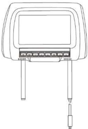
Using the wires provided, complete the audio, video and power connections in your vehicle as shown in the diagram below.
natural_image
Line drawing of a device rear panel with two connectors and a central display (no text or symbols)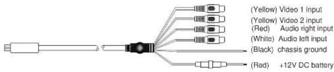
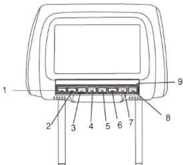
FEATURES AND CONTROLS OSD
- Power switch
2.V1 switch
3.V2 switch - Decrease
5.Menu
6.Increase - Mode switch
8.Sys switch
9.Remote sensor
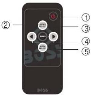
① POWER
Press to turn unit ON or OFF.
② A/V SELECT
Use this button to switch between Video source1 and Video source 2.
③ MENU
This button enables the on-screen display menu system. Once enabled, this button is used as an ENTER button.
④ UP/DOWN BUTTONS
This buttons are used to increase or decrease parameters in the on-screen display menu system.
⑤ MODE SELECT
This button switch display ratio between 4:3 and 16:9.
On-screen (OSD) menu system - SCREEN MONITOR
- Press the "POWER" key on monitor or remote controller to turn on the monitor.
- Press the "MENU" key on monitor or remote unit, the OSD
(ON SCREEN DISPLAY) menu will be shown on the display as below.
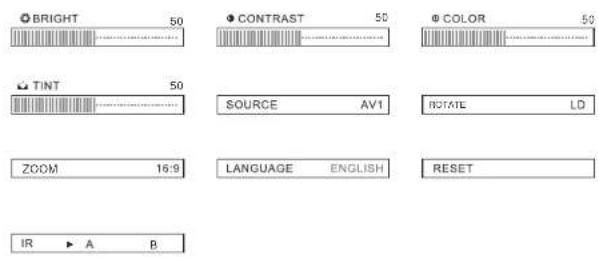
| BRIGHT | ROTATE |
| CONTRAST | ZOOM |
| COLOR | LANGUAGE |
| TINT | RESET |
| SOURCE | IR |
- Press "MENU" key on monitor or remote unit to select the adjustment item. Then press "+" or "-" key to adjust the new setting value. Each adjustment item is shown as below:
*BRIGHT Adjustment
Pressing "+" key, the screen color gets more bright. Pressing "-" key, the screen color gets less bright.
*CONTRAST Adjustment
Pressing "+" key, the screen gets high intensity. Pressing "-" key, the screen gets lower intensity.
*COLOR Adjustment
Pressing "+" key, the screen color gets richer. Pressing "-" key, the screen color gets lighter.
*TINT Adjustment
Pressing "+" key, the screen gets greenish. Pressing "-" key, the screen gets reddish.
*ZOOM Adjustment
Press "+" or "-" key to select the picture image to 16:9 or 4:3 display.
*SOURCE Adjustment
Press "+" or "-" key to change to AV1 or AV2.
*IR Adjustment
Press "+" or "-"key to select the IR channel to "A" or "B".
*ROTATE Adjustment
Reverses the displayed image (useful with rear camera systems)
*LANGUAGE Adjustment
Press "+" or "-" key to select the different OSD language.
*RESET Adjustment
Press "+" or "-" key to return all setting to factor values.
INSTALLATION
Function Setting
Menu instruction
The following menus will appear when pressing "MENU" button, press "+" - to select the one you want.
- Take down the original pillow in the car.
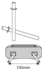
- Install the pillow of this monitor. Adjust the steel tube in or out (max. interval: 5cm) according to the interval between pillow holes so that the interval between steel tubes of the pillow monitor coincides with that between steel tubes of the original pillow.
- The circuit connection of the pillow monitor is very simple. As shown in Fig. connect the +12V power of the sound system (red line to +, black line to ground), and then connect the video signals.
- After the pillow monitor is connected properly, press the Power switch and the screen lights up; press Menu, adjust Analog Plus or Analog Minus to the desired mode, or use the remote control if any.
INSTALLATION
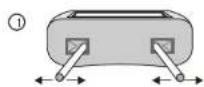
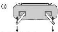
- Tubes could be adjusted from left and right.
- Tubes could be adjusted from front and back.
Install the pillow
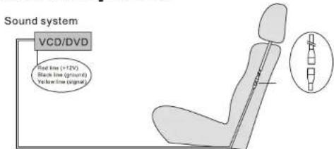
The circuit connection of the pillow monitor is very simple. As shown in Fig. connect the +12V power of the sound system (red line to +, black line to ground), and then connect the video signals. Connect the video signals, hide the connector in the base
How to use the accessory tubes
natural_image
Technical diagram of a mechanical device with a cylindrical component and a rectangular base, annotated with 105mm dimension (no text or symbols on the components)Min. Interval
As pillow holes are of different sizes, this product is provided with two tubes 12mm in diameter. When the pillow hole is large, fit this fitting to meet different needs.
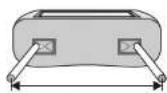
190mm
Max. Interval
Brand : BOSS
Model : Headrest Widescreen
Category : Monitor