JA-87P - Security Camera Jablotron - Free user manual and instructions
Find the device manual for free JA-87P Jablotron in PDF.


| Product Type | Dual Zone Outdoor Wireless Motion Detector (Curtain Lens) |
| Model | JA-87P |
| Compatible System | JA-8x OASIS |
| Detection Zones | 2 zones, 5° angular width |
| Detection Range | 2 m or 5 m (selectable) |
| Installation Height | 0.8 – 1.2 m above ground |
| Object Motion Speed | 0.3 – 1.5 m/s |
| Detection Angle Adjustment | 190° range, locking every 5° |
| Power Supply | 1x LS(T)14500 (AA 3.6 V / 2 Ah) lithium battery |
| Average Battery Lifetime | Approx. 3 years (with 120 s energy saving mode) |
| Operating Frequency | 868 MHz |
| Range to Control Panel | Up to 300 m with direct visibility |
| Tamper Protection | 3 tamper contacts (front on detection part, front and rear on transmission part) |
| Anti-Masking | Enabled/disabled via switch |
| Temperature Range | -20°C to +60°C |
| Max. Relative Humidity | 95% |
| Ingress Protection | IP55 |
| Weight | 190 g |
| Compliance | ETSI EN 300 220, EN 50130-4, EN 55022, EN 60950-1, CTU VO-R/10/06.2009-11 |
| Battery Low Signal | Automatic transmission to control panel |
| Energy Saving Mode | 5 sec or 120 sec (selectable) |
| LED Indicator | Enabled/disabled via switch |
| Detection Immunity | Normal or increased (selectable) |
| Fault Signal Output | N.O. or N.C. (selectable) |
| Maintenance | Clean lens with soft dry cloth; replace battery when low (use 3.6V AA only) |
Frequently Asked Questions - JA-87P Jablotron
User questions about JA-87P Jablotron
0 question about this device. Answer the ones you know or ask your own.
Ask a new question about this device
Download the instructions for your Security Camera in PDF format for free! Find your manual JA-87P - Jablotron and take your electronic device back in hand. On this page are published all the documents necessary for the use of your device. JA-87P by Jablotron.
USER MANUAL JA-87P Jablotron
The JA-87P dual zone outdoor wireless motion detector - curtain
The JA-87P wireless outdoor detector with curtain lens characteristics is designed to indicate disturbances outside the building caused by human bodies. It is a dual zone outdoor detector by Optex with a 5° angular width detection zone which makes it very suitable for guarding narrow spaces such as balconies, French doors, terraces, etc. It is supplemented with a transmitter compatible with JA-8x OASIS systems. Both the detector and the transmitter are powered by a lithium battery. The common power supply is beneficial as the low battery signal is transmitted to a control panel as standard. The detector is equipped with three TAMPER contacts (at the front on the detection part and the front and rear on the transmission part), which immediately report opening of the detector cover or its tearing from the place of installation. The detector can also have the anti-masking function activated. The detector reports its current status via control transmissions to the system.
Detector position and installation
The following instructions should be followed when selecting the place for detector installation:
- The detector should be attached to a vertical wall
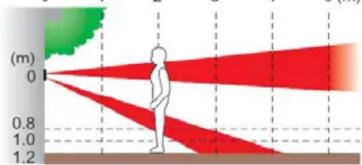
- The detector should be installed 0.8 - 1.2 m above the ground
- The best movement detection is provided when the detection zones intersect
- No other moving objects (bushes, trees, high grass, etc.) should be situated in the field of sight of the detector. Avoid direct action by strong sources of light (sun reflections).
Detector installation procedure
-
The detector consists of two parts: the detecting one (1) and the transmission one (2). Their mutual position can be adjusted according to the picture. Punch holes for wires in the plastic transmission part of the detector depending on which position of the parts you have selected (there are holes indicated on the plastic for this purpose).
-
Unscrew and remove the detecting part cover. The position of the detecting part

is fixed with a toothed plastic lug which should be moved upwards. Then remove the whole part with the electronics by bending the upper part of the plastic and pulling the swivel part towards you. You will thus make the installation holes located under this part accessible.
Warning: Do not touch the sensors during handling
- Pull the bundle of cables through the punched hole into the transmission part.
- Attach the detecting and the transmission part to the wall using the supplied screws (mind the correct orientation – marked with an upward-facing arrow on the plastic).
- Reassemble the detecting part.
- Use the supplied self-adhesive plastic posts to attach the transmission module to the bottom of the transmission part so that the function switch is located in the top left corner. Place the DPS as high as possible – the bottom screw which attaches the plastic base to the wall must be visible. You will thus avoid possible interference with the antenna resulting in reduced detector range.
- Use connectors to interconnect the wiring between the detector parts (cannot be mixed up).
- If you use the rear tamper (recommended), remove the jumper from the pins on the board and plug in the tamper connector (regardless of polarity). The ring magnet included in the package should be attached on the wall in the corresponding position under the transmission part of the detector.
Switching on and enrolling the detector into the system

Study the control panel (receiver unit) installation manual before inserting the battery. Use AA 3.6V lithium batteries only. The correct position of the battery is indicated on the battery holder. When the battery has been installed, the transmitter sends a signal which enrolls it to the control panel. The control panel must be in enrollment mode at that time. Use switch no. 2 to set system reaction to detected movement (ON = instant or OFF = delay). Switch no. 1 should remain in the OFF position.
Setting up the optical part of the detector
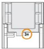
A detection range of 5 m or 2 m can be set. The setting is done by turning the bottom detector lens (closer to the centre of the cover). The lens shape is
designed so that its projecting part uncovers the detection distance which you have selected when it is inserted back into the plastic base (see the picture below). Do not turn the upper lens!


Other detector properties can be set using a switch in the detector
| ON OFF | ||
| 1 | test mode | normal operation |
| 2 | 5 sec energy saving mode | 120 sec |
| 3 | fault signal triggers N.O | NC |
| 4 | LED enabled | LED disabled |
| 5 | normal immunity of detection | increased immunity of detection |
| 6 | anti-masking enabled | anti-masking disabled |
The default settings are in bold letters.
The detection part can be turned in a 190^ range with locking after each 5^ . When the required angle has been set, use the plastic lug to prevent further movement. The angle is fixed completely when the cover with the lenses is put back and the screw is tightened.

line
| Angle (degrees) | Pitch Range (ft.) | | --------------- | ----------------- | | 0' | 0 | | 4 | 0.2 | | 5' | 0.1 | | 10' | 0.3 | | 15' | 0.8 |Checking the status of and replacing batteries
The detector checks battery status and automatically reports a low battery to the system. The detector remains fully functional. The batteries should be changed as soon as possible (within 1 week).
The control panel must be in service or maintenance mode before you start changing the battery. Use 3.6V AA batteries only. When the cover has been closed, the detector switches to normal operating status automatically.
Note: If you insert a nearly drained battery into the detector by mistake, the sensor does not start working and this status is indicated with transmitter LED flashing. If the battery is completely drained, the detector does not react at all.
Technical specifications
| Power | 1x type LS(T)14500 (AA 3.6 V / 2 Ah) lithium battery |
| Average battery lifetime | approx. 3 years (with 120 s energy saving mode) |
| Operating frequency band | 868 MHz |
| Range – distance from the control panel | up to 300 m with direct visibility |
| Optex detector parameters | |
| Detection characteristics | 2 or 5 m / 5° |
| Recommended installation height | 0.8 – 1.2 m |
| Object motion speed | 0.3 – 1.5 m / s |
| Detector cover conformance | IP55 |
| Environment according to EN 50131-1 | IV |
| Operating temperature range | -20°C to +60°C |
| Max. relative humidity of the environment | 95% |
| Security rating | according to OPTEX |
| Complies with | ETSI EN 300 220, EN 50130-4, EN 55022, EN 60950-1 |
| Weight | 190 g |
| Can be operated according to | CTU VO-R/10/06.2009-11 |

Jablotron Ltd. hereby declares that the JA-87P is in compliance with the essential requirements and other relevant provisions of Directive 1999/5/EC. The original of the conformity assessment can be found at www.jablotron.com - Technical Support section
Note: Although this product does not contain any harmful materials we suggest you return the product to the dealer or directly to the producer after use.
JABLOTRON
JABLOTRON ALARMS a.s.
Pod Skalkou 4567/33
lonec had Nisou Czech Republic
Tel: +420 483 559 911
Fax: +420 483 559 993
- The JA-87P dual zone outdoor wireless motion detector - curtain
- Detector position and installation
- Detector installation procedure
- Warning: Do not touch the sensors during handling
- Switching on and enrolling the detector into the system
- Setting up the optical part of the detector
- Checking the status of and replacing batteries
- JABLOTRON
Brand : Jablotron
Model : JA-87P
Category : Security Camera