
TC304 - Car radio HARMAN KARDON - Free user manual and instructions
Find the device manual for free TC304 HARMAN KARDON in PDF.


| Product Type | 4-Channel Car Amplifier |
| Brand | Harman Kardon |
| Model | TC304 |
| Continuous Power Output (RMS) | 50W x 4 channels @ 4 ohms; 75W x 4 channels @ 2 ohms; 50W x 2 channels @ 4 ohms + 150W x 1 channel @ 4 ohms; 75W x 2 channels @ 2 ohms + 150W x 1 channel @ 4 ohms; 150W x 2 channels @ 4 ohms |
| HCC (High Instantaneous Current Capability) | ±50A |
| THD (4 ohms/2 ohms) | No more than 0.1%/0.2% |
| Negative Feedback | 25dB |
| Frequency Response | 10Hz - 100,000Hz +0, -3dB |
| Signal-to-Noise Ratio (referred to rated power) | 100dB |
| Input Sensitivity (Continuously Variable) | 0.25V - 2.5V (line-level to high-level) |
| Input Impedance | 22 kohms (center pin and outer shield) |
| Power Supply | DC +14.4V (9V-16V usable), negative ground |
| Typical Current Requirements (Idle) | 4.0A |
| Typical Current Requirements (Music Signal) | 10A (4 ohms/channel), 15A (2 ohms/channel) |
| Typical Current Requirements (Sine Wave) | 30A (4 ohms/channel), 45A (2 ohms/channel) |
| Dimensions (L x W x H) | 16-5/8" x 12-7/8" x 3-1/4" (422 x 327 x 83 mm) |
| Weight | 14 lbs 12 oz (6.7 kg) |
| Cooling System | Transverse tunnel cooled with two-stage music-linked fan |
| Special Features | Bridgeable, simultaneous stereo + bridged mono, 50Hz boost, balanced differential inputs, fully regulated power supply |
| Speaker Impedance (min.) | 2 ohms stereo, 4 ohms bridged mono |
| Safety Protections | Short circuit, thermal, undervoltage/overvoltage, DC offset |
| Installation Recommendations | Professional installation recommended; use 10 AWG or larger for power; 18 AWG or larger for speakers |
| Warranty | Limited warranty; retain sales receipt for proof of purchase |
Frequently Asked Questions - TC304 HARMAN KARDON
User questions about TC304 HARMAN KARDON
0 question about this device. Answer the ones you know or ask your own.
Ask a new question about this device
Download the instructions for your Car radio in PDF format for free! Find your manual TC304 - HARMAN KARDON and take your electronic device back in hand. On this page are published all the documents necessary for the use of your device. TC304 by HARMAN KARDON.
USER MANUAL TC304 HARMAN KARDON
TC Series High Fidelity Car Amplifiers
TC600
TC300
TC304
Owner's Manual
Thank you for choosing a Harman Kardon Tunnel Cooled amplifier. This is a superb piece of high fidelity equipment that has been meticulously designed to provide you with many hours of enjoyment.
Harman Kardon's Tunnel Cooled amplifiers are the result of an extensive engineering project to create the finest automotive high-fidelity amplifiers available. These amplifiers provide superior performance, can operate under extreme environmental conditions, and are highly adaptable to various system configurations.
This manual describes the features and capabilities of your new amplifier. In addition, it describes the proper methods for connecting your amplifier to your system. Please read this owner's manual and carefully follow the instructions for connection.
Table of Contents
Harman Kardon design philosophy .....2
TC600, TC300, and TC304 features ..... 3
Introduction....5
Installation precautions 6
Charging system considerations .....7
Mounting location 7
System configurations....8
Connecting the TC-series amplifier ..... 11
General information 11
Power connections 13
Audio input connections 17
Speaker output connections....18
Controls and operation 19
Application drawings 22
Series-Parallel and minimum impedance speaker connection 29
Troubleshooting checklist 31
Fan reversal for multiple amplifier installations ....33
Specifications 34
Harman Kardon design philosophy
The TC Series amplifiers employ the key Harman Kardon design principles of high-instantaneous current capability (HCC), ultrawidebandwidth, low negative feedback, and fully discrete preamp and output circuitry.
• HCC (High-Instantaneous Current Capability)
While reproducing dynamic music signals, the instantaneous impedances of nearly all loudspeakers drop to less than a third of the nominal rating. These low momentary impedances typically require three to six times more current from the amplifier than would a nominal 4-ohm resistive load. The TC600 amplifier can supply 100 amperes of instantaneous current, while the TC300 and TC304 can supply 50 amperes. This HCC provides control over the low impedance and fluctuating phase angles produced by normally operating speakers, ensuring that your speakers will be able to continually reproduce the entire dynamic range of music without premature clipping or current limiting.
- Bridgeable
All TC Series amplifiers are designed to provide increased power into 2 ohms stereo or 4 ohms bridged. Unlike many lower-quality amplifiers, the TC Series amplifiers can be bridged for increased power. Stable, reliable operation in these higher power modes is assured by the TC Series' wide-margin Safe Operating Area (S.O.A.), which anticipates the toughest operating conditions.
• Ultrawidebandwidth
Unlike conventional automotive amplifiers, the TC600, TC300, and TC304 can reproduce musical frequencies ranging from less than 10Hz to more than 100kHz. This ultrawidebandwidth improves the accuracy of reproduction of transient signals and ensures phase linearity.
- Low negative feedback
This design philosophy is used by the world's most exclusive amplifiers. It requires the highest quality internal components, and results in an extremely stable amplifier with unmeasurable TIM distortion and absolutely outstanding imaging characteristics.
• Fully discrete circuitry
Rather than employing inexpensive integrated circuits, which reduce bandwidth and increase required negative
TC600, TC300, and TC304 Features
feedback, the TC Series amplifiers use completely discrete (separate) electronic components for greatly improved linearity and less distortion.
Ultrawidebandwidth combined with low negative feedback and fully discrete curcuity maintains the correct harmonic and phase relationships in your music, providing superior imaging and definition.
Designed and manufactured in the U.S.A.
The TC Series amplifiers were designed with the aid of CAD/CAM computer systems at Harman Kardon's state-of-the-art industrial complex. The result is rugged, high-performance amplifiers employing only the highest-quality parts and materials, including double-sided fiberglass-epoxy printed circuit boards and high-current capacity bipolar transistors.
Major heat-producing components in the amplifier are mounted directly to the center heat sink, localizing the area to be cooled. Harman Kardon's exclusive transverse tunnel cooled design employs a fan to eliminate heat directly from the heat sink, enabling the amplifier to remain cool to the touch and permitting installation in restricted spaces, such as under car seats. This exclusive design not only protects the preamplifier and power supply components from high temperatures, but also keeps dust and dirt from contaminating the inside of the amplifier, further ensuring reliable operation.
Two-stage music-linked cooling fan speed
The music link whisper fan operates inaudibly until the music volume rises, then goes to a higher speed for more efficient cooling without interference with your listening pleasure. The fan returns to its inaudible state between musical passages.
Reversible fan
For side-by-side multi-amp installations, the fan in each TC Series amplifier can be reversed, providing control over the direction of the cooling air flow. This enables you to prevent the warm air from one amp from being vented into the tunnel of the next amp.
Simultaneous stereo plus bridged mono operation
For one-amplifier stereo satellite/mono subwoofer systems, the TC Series amplifiers can provide stereo and bridged mono operation simultaneously, eliminating the need for electronic crossovers and additional amplifiers.
50Hz boost
All TC Series amplifiers provide 50Hz boost equalization, enabling you to adapt your sound to your personal taste and compensate for acoustic limits inherent in the automotive environment.
Fully regulated high-capacity power supply
The high-capacity power supply is fully regulated, ensuring stable amplifier operation over a wide voltage range and completely eliminating damage to speakers due to DC leakage.
B+ and remote-on power noise filtering
The TC Series amplifiers contain power-supply filters that effectively reject any power-supply-related noise, such as alternator whine. The 12-volt B+ main power input is filtered by a bank of capacitors and a large high-current inductor.
Balanced differential variable-gain inputs
The input circuitry on TC Series amplifiers isolates signal cables from potential ground loops and radiated noise. In addition, it allows preamp or high-level (speaker) inputs to be directly connected to the amplifier inputs.
Introduction
This manual covers all three of the Harman Kardon TC Series amplifiers: the TC600, TC300, and TC304. Because of their clean, powerful design, these amplifiers can be used full-range or in specialized multi-amp systems as bass, midrange, or treble amplifiers.
The TC600 and TC300 are two-channel (stereo) amplifiers that can be bridged into a single channel. The TC304 is a four-channel amplifier that can be configured for four, three, or two discrete channels. All of the TC Series amplifiers are capable of operating in simultaneous stereo plus bridged mono mode, which allows for immense flexibility in system design and future upgrade potential.
Please read this manual for information about system design considerations, connections, and operation. Before you begin your installation, determine your speaker configuration, wiring route, and location of the amplifier(s). Retain this manual for future reference.
Important
The TC Series amplifiers are professional-quality amplifiers that can be incorporated into any automotive system, from the simplest to the most complex. We strongly recommend professional installation of your TC Series amplifier to ensure that you obtain the optimum performance from your entire system.
Warranty card
Fill out the warranty card and save your sales receipt. Your sales receipt is your proof of purchase and you will need it to establish the date on which your warranty begins. You will be required to show it if service is necessary during the duration of the Limited Warranty.
Caution
Listening at extremely loud sound levels can cause a temporary loss in your hearing acuity. Continued exposure can eventually cause this loss to become permanent. We caution you to be aware of the long-term effects of sustained high-volume sound, and we recommend that you use discretion when listening for extended periods.
Installation precautions
- Disconnect the negative (−) battery terminal before beginning your installation, and do not reconnect it until all connections have been made and you are completely finished with your installation.
- As the very last step before reconnecting the battery, connect the positive power lead (sometimes referred to as B+) from the amplifier to the battery terminal.
- Important: To prevent serious short-circuits that can do major damage (including potential for fire), you must install a fuse within 18" of the positive (+) battery terminal on the positive B+ power lead to the amplifier. (See the "Connections" section for information about fuse size).
- Make sure that the inlets and outlets for the amplifier's cooling fan are unobstructed. You must install the amplifier in such a way as to allow free air flow through the cooling tunnel to ensure that the amplifier will be able to dissipate its heat.
- Pay particular attention to the power ratings of the speakers you choose. Many speakers are not capable of handling the high power produced by the TC Series amplifiers. Match your speakers to the power ratings of the amplifier(s) you will be using, and never operate your speakers at higher levels than specified.
Charging system considerations
The TC600, TC300, and TC304 are high-performance amplifiers whose current demands place an additional load on your car's battery and charging system. Depending on the volume at which you are playing your system, the amplifier can draw an average of 20–40 amperes, and under certain extreme operating conditions, can draw up to 90 amperes in the case of the TC600.
Because of the additional demand, the life of your car's battery and charging system may be shorter than it would have been before you installed your music system. You may need to install a heavy-duty charging system and a high-quality heavy-duty battery to support the higher demands on the charging system. Depending on your listening habits, you may want to install a second battery and an isolation switching system. Consult your Harman Kardon dealer for professional assistance.
Mounting location
Harman Kardon's tunnel cooled design keeps your amplifier cool to the touch, enabling you to install it even in a very confined space, such as under a seat with limited clearance. Just be sure that you don't block or restrict the inlet or outlet to the amplifier's tunnel, so air can be circulated freely by the fan. This cooling method allows the amplifier to be positioned in any orientation (horizontal, vertical, upside down).
Do not install your amplifier in a location where it would be exposed to rain, moisture, or direct sun, and do not allow dirt or foreign objects to enter the cooling tunnel.
Use the amplifier itself as a template for marking the mounting holes. Before you drill mounting holes, make sure that you know what is located directly behind the panel you're drilling through (e.g., gas tank, brake lines, wires, etc.).
System configurations
This section describes some of the system configurations possible with the TC Series amplifiers.
Low-level input to amplifier
TC-Series amplifiers are most commonly used with a low-level (preamp) input signal from the head unit. A control on the TC Series amplifiers enables you to adjust the input signal level for optimum performance. (See the "Controls and operations" section for information on adjusting input level.)
High-level input to amplifier
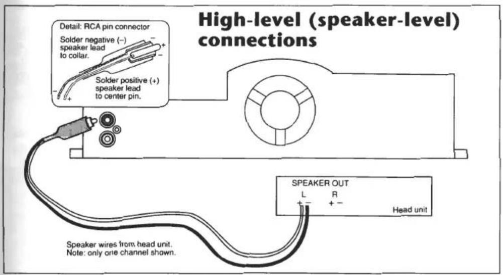
All TC Series amplifiers can also accept a high-level (speaker-level) input signal from a head unit that has no preamp-level outputs. In this situation, the leads from your head unit that would ordinarily connect directly to your speakers are instead connected to the input of the TC Series amplifier. A control on the TC Series amplifier enables you to adjust the input signal level for optimum performance. (See the "Controls and operation" section for information on adjusting input level.)
Normal stereo or four-channel full-range operation
("Full-range" means that a single amplifier provides the entire spectrum of audio frequencies to a speaker or speakers with no electronic crossover used.) Either the TC600 or the TC300 amplifier can be used in a normal two-channel stereo installation in which the amplifier provides power for both the left and right channels. The TC304 can be used in a normal four-channel installation in which the amplifier provides power for left and right channels, both front and rear.
Dedicated full-range bridged amplifier operation
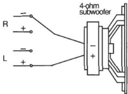
Any TC Series amplifier can be bridged, combining two of its channels into a single channel to provide higher power. The TC600 or TC300 can be bridged to convert from stereo operation to higher-power mono operation. In this configuration, the amplifier provides all its power into a single channel. The TC304, being a four-, three-, two-channel amplifier, can be bridged to combine one or two of its channel pairs into one or two single mono channels.
Bridged amplifier operation with electronic crossover
If you install an electronic crossover between the head unit and the TC Series amplifier, you have several options for using TC Series amplifiers in bridged mode, such as:
- Use the TC600 as a dedicated mono amplifier running parallel subwoofers. Note: Because there are very few woofers that can handle 600 watts of continuous power without damage, we do not recommend using the TC600 in bridged mono mode with most single subwoofers.
- Use the TC300 as a dedicated mono amplifier running a single subwoofer or other combinations of series/parallel woofers.
- Use the TC304 in one of two ways: (a) as a dedicated two-channel amplifier running two single subwoofers, or (b) as a stereo high-pass amplifier to two stereo channels and as a mono low-pass amplifier to a mono subwoofer channel.
- Use the TC304 as a four-channel high-pass satellite amplifier, and use either a TC600 or TC300 as a dedicated subwoofer amplifier.
Simultaneous bridged-mono/ stereo satellite operation
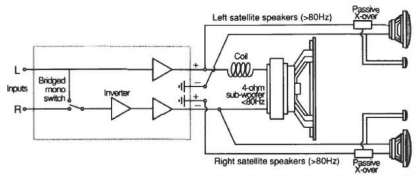
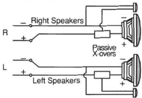
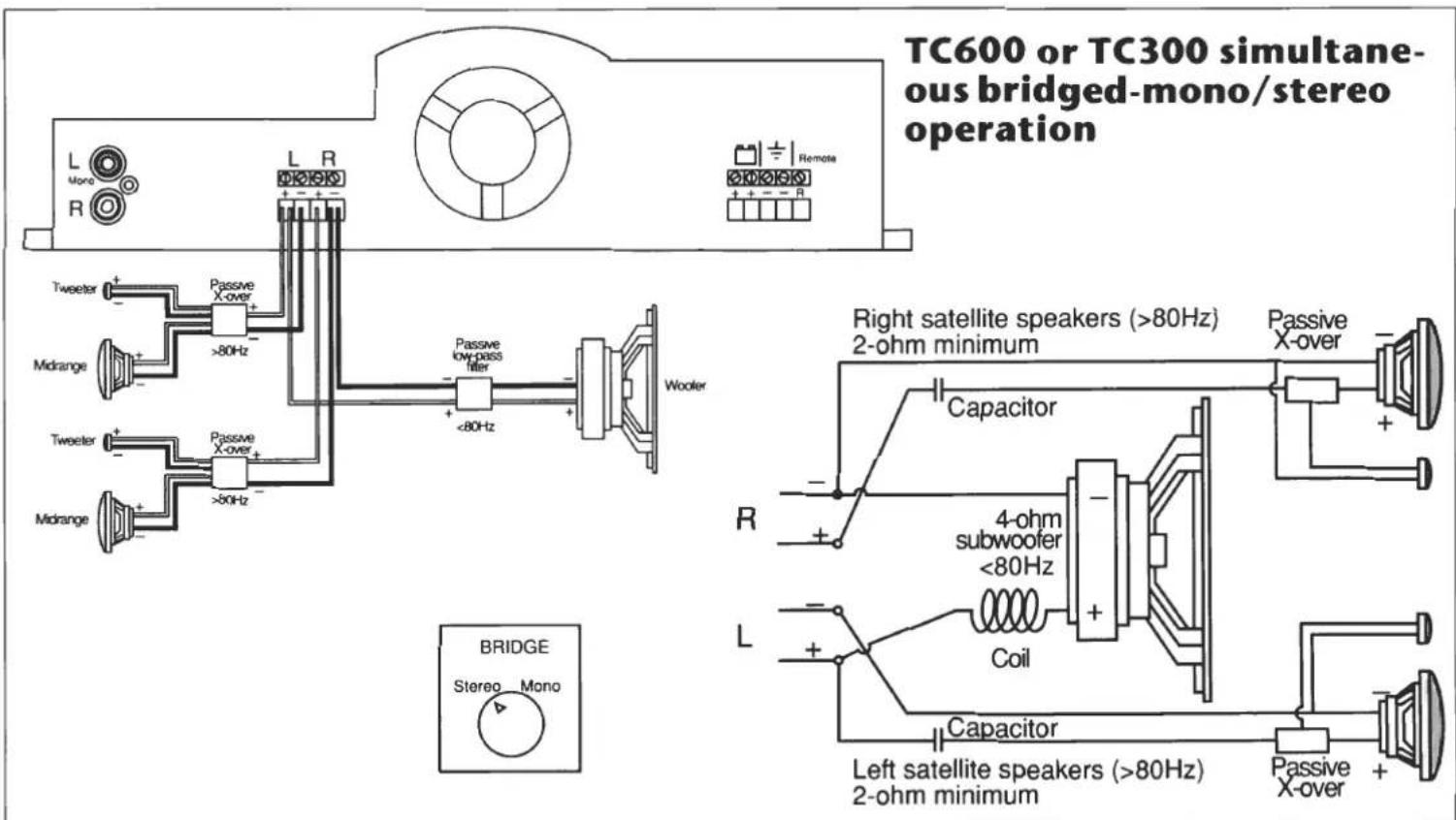
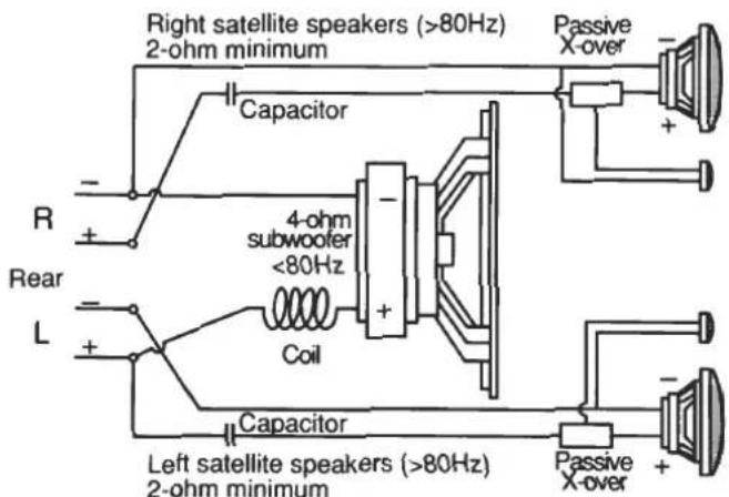
You can use any of the TC Series amplifiers in a simultaneous bridge-mono/stereo mode (also known as center-channel configuration or derived three-channel operation). In this configuration, a single amplifier runs a stereo pair of satellite speakers as well as a single subwoofer speaker simultaneously. With a TC Series amplifier, this configuration does not require the use of either an active electronic crossover or extra amplifiers. However, you will need to use passive crossovers on all three speakers so the stereo satellite speakers and the subwoofer do not operate in the same frequency range.
- If you're using a two-channel amplifier (either the TC600 or TC300), the speaker leads will be connected to both the normal stereo connectors and to the bridged-mono connectors simultaneously.
- If you're using the TC304 four-channel amplifier, the amplifier can operate in normal four-channel mode and simultaneously provide bridged power output on either one or both front and rear channel
speakers, or from the left front to right rear and right front to left rear for non-fade bass operation.
4,3,2 operation using the TC304 four-channel amplifier
The TC 304 four-channel amplifier can be configured to provide either four, three, or two separate channels of power. Some examples of different types of 4,3,2, operation have been described in this manual, but there are many more possible application combinations. The 4,3,2 operation of the TC304, combined with simultaneous bridged operation, provides almost unlimited flexibility for automotive system design.
Simultaneous bridged-mono/stereo operation
Connecting the TC-series amplifier
This section is divided into four separate parts:
- General information
- Power connections
- Audio input connections (from the head unit to the amplifier)
- Speaker output connections (from the amplifier to the speakers)
Please be sure you read all four parts to ensure that your amplifier is connected properly.
General information
DISCONNECT THE BATTERY'S NEGATIVE (-) TERMINAL BEFORE YOU BEGIN YOUR INSTALLATION, AND DO NOT RECONNECT IT UNTIL YOU ARE COMPLETELY FINISHED!
Connection tips:
- Do not connect the main positive lead (B+) from the amplifier to the battery until after all other connections have been made.
- Use the proper gauge of wire: 10 gauge or larger from the amplifier to the battery, and 18 gauge or larger from the amplifier to the speakers.
- If you choose to use crimp-type connectors in your system, use high-quality connectors of the proper size, and crimp them correctly to ensure optimum electrical contact.
-
Be sure to solder any splices in your wire, and seal the splice with heat-shrink tubing or electrical tape.
-
The connectors on TC Series amplifiers are large enough to accept up to 10-gauge wire. If you want to use a heavier gauge of wire than will fit into the connector, remove one strand at a time until the end of the wire can fit. Even though strands are removed at the connector end, you still receive the benefits of the heavier-gauge wire, since the significant loss in a long run of wire occurs along its length, and not at its relatively short termination point.
- The screw-type connector used on TC Series amplifiers works most effectively when the stranded wire is not tinned with solder. When the tiny wire strands are loose, the connector can compact them uniformly, achieving maximum surface area contact between the wire and the connector. Use a good screwdriver and tighten the connector securely enough to ensure that the wire will not pull out.
Wire-routing tips:
- Plan your wire routing carefully before you begin your installation.
- Always route signal cables separately from power cables to avoid noise in the system. For example, run your power cables along one side of the car chassis and the signal cables down the opposite side.
- Keep each ground wire as short as possible to avoid power loss and the possibility of introducing noise into your system.
- Use grommets or other protective devices when running wires through metal parts.
- If you have mounted several amplifiers and accessory devices (e.g., electronic crossovers, equalizers, etc.) together in the same area, connect all the ground leads from these devices to the same ground point on the metal chassis of the car. Do not connect one unit to another unit's negative ground terminal and rely on the second unit's ground wire to ground both units (daisy-chaining). This configuration can cause a ground loop, which can introduce noise into the system.
Power connections
Your TC Series amplifier requires a positive 12V battery connection and a negative 12V ground. Use 10-gauge or larger wire for these connections.
TC600
12V Positive (B+) connection
Remember: Connecting your amplifier to the positive terminal of your battery is the last thing you do, after all other connections in your system have been completed.
The TC600 requires two individual wires connected to the two battery (+) terminals on the amplifier. Make sure you route these leads separately from the preamp output cables to avoid the possibility of noise in the system. There are two methods you can use to complete this connection:
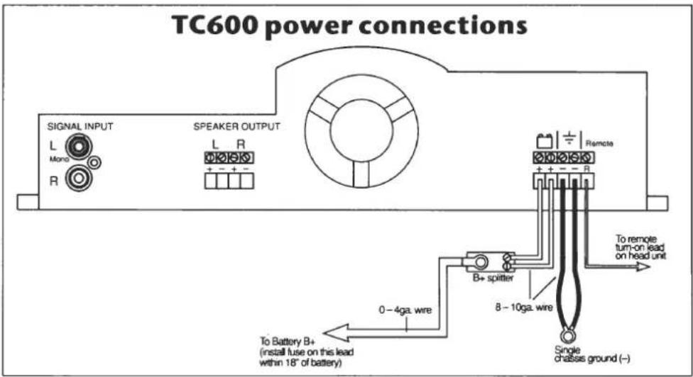
Option 1: Connect two 10-gauge or larger wires to the positive terminal on the battery. Within 18" of the battery terminal, insert a 45-amp fuse, fuseable link, or circuit breaker in each lead. Connect each lead to one of the two battery (+) terminals on the TC600.
Option 2: Connect a single 4-gauge or larger lead to the positive terminal on the battery. Within 18" of the battery terminal, insert a 90-amp fuse, fuseable link or circuit breaker in the lead. Run the single lead to the area where you have mounted your TC600, then use a splitter to split to two 10-gauge leads that then connect to the two battery + terminals on the TC600.
12V Ground (B-) connection
Connect two 10-gauge or larger wires to the two ground (−) connectors on the TC600, then run both leads to the same point on the metal chassis of the car. Make sure you scrape down to bare metal, and make sure that the metal is directly part of the main vehicle chassis. Keep the ground leads as short as possible.
TC300 or TC304
12V Positive (B+) connection
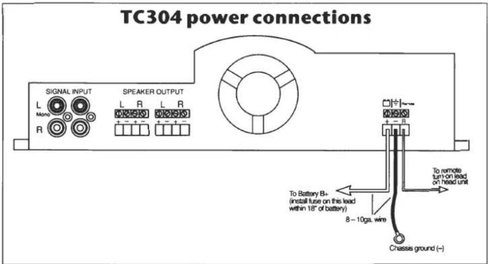
Remember: Connecting your amplifier to the positive terminal of your battery is the last thing you do, after all other connections in your system have been completed. Connect a 10-gauge or larger wire to the positive terminal on the battery. Within 18" of the battery terminal, insert a 45-amp fuse, fuseable link, or circuit breaker in the lead. Connect the lead to the battery (+) terminal on the TC300 or TC304. Make sure you route this lead separately from the preamp output cables to avoid the possibility of noise in the system.
12V Ground (B-) connection
Connect a single 10-gauge or larger wire to the ground (−) connector on the amp, then run the lead to the metal chassis of the car. Make sure you scrape down to bare metal, and make sure that the metal is directly part of the main vehicle chassis. Keep the ground lead as short as possible.
Remote-on
Many head units provide a remote-on lead, which connects directly to the Remote connector on your TC Series amplifier. Turning on your head unit will, in turn, automatically turn on the amplifier. If your head unit does not have a remote-on lead, you can still wire your system for remote turn-on by using one of these options:
Option 1: Connect the antenna power lead to the Remote terminal on the TC Series amplifier. Note: This configuration may require that you have the power to the radio on when you play a tape or CD.
Option 2: Wire a switch in the passenger compartment to switch the positive terminal on the battery (+12V) to the Remote terminal on the amplifier. Alternatively, you can use the accessory position on the ignition switch to switch +12V to the Remote terminal.
Audio input connections
There are two types of input signals that your TC Series amplifier may receive: low-level (preamp-level) output or high-level (speaker-level) output.
Low-level (preamp-level) connections
Connect the left and right preamp output cables from your head unit, electronic crossover, low-level equalizer (commonly referred to as a passive equalizer), or preamplifier to the left and right INPUT RCA connectors on your TC Series amplifier. (See the “Controls and operations” section for information about adjusting input level.)
You may want to use high-quality preamp cables (although noise at this point should not be a factor because the differential INPUT connectors on the TC Series amplifiers are capable of rejecting radiated noise induced in cables). If you decide to use higher-quality preamp cables, use the type with a shielded, twisted pair of signal wires, if possible. The separate shield should not be grounded at the amplifier end.
High-level (speaker-level) connections
If your head unit has low-level (preamp-level) connectors available, connect as described in the previous section. If only speaker wires are available, connect as described here.
Solder each pair of speaker leads from the head unit to a male RCA connector. Connect the positive lead to the center pin of the RCA connector, and the negative lead to the outside shield of the connector. Then attach each RCA connector to the INPUT connectors on the TC Series amplifier. (See the "Controls and operations" section for information about adjusting input level.)
Speaker output connections
The size and quality of the wire you use to connect your speakers to your TC Series amplifier can affect the sound quality of your system. Since the lengths of speaker leads in a car are relatively short, any speaker wire of 18-gauge or larger should perform satisfactorily. However, audiophile speaker cables may offer better performance.
For information about connecting specific speaker configurations, see the "Application drawings" section of this manual.
Controls and operation
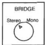
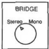
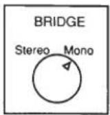
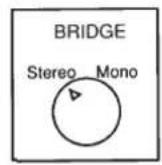
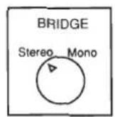
Bridged mono/stereo switch
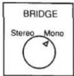
- Set this switch to STEREO when you are using both left and right RCA input connections.
- Set this switch to MONO when you are using only the left (mono) RCA connector.
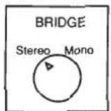
- The TC304 has two controls, one for the front channels and one for the rear channels. Set these switches as described above, depending on which input connectors you are using. Note: For simultaneous bridged mono/stereo satellite operation, set this switch to STEREO.
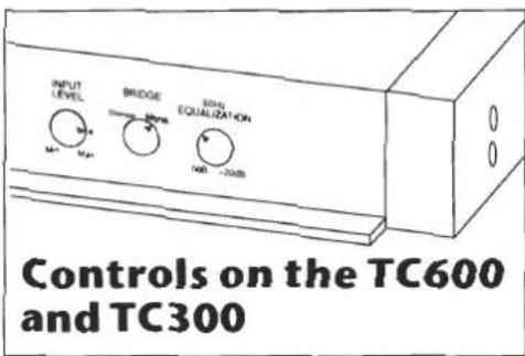
Input sensitivity control
WARNING: When adjusting and testing the system for proper amplifier input sensitivity control level, you may easily reach amplifier output levels which can damage speakers. Do not operate the system at high output levels when distortion is present.
Test the system for correct amplifier input level setting by momentarily advancing and reducing the head unit volume control to successively higher levels as long as there is no distortion up to a maximum of 7/8 volume control rotation. If you hear distortion (clipping) on a successive increment, immediately turn down the head unit volume control and do not operate the unit above this level unless the amplifier input sensitivity is changed as described in the following sections.
For standard low-level (preamp-level) inputs:
Most head units provide a nominal low-level (preamp level) output signal of approximately 500mV. On your amplifier chassis is a dot indicator located at the 3 o'clock position on the INPUT control. The INPUT control should be set to this position for normal preamp-type head units.
If the system does not distort when tested, and plays loudly enough, leave the INPUT control at this setting. However, if operation is not satisfactory, or your head unit has a non-standard output signal, use the adjustment method described in the following section.
For nonstandard low-level (preamp-level) and high-level (speaker-level) inputs:
Turn the INPUT SENSITIVITY control all the way down to MIN (full counterclockwise). Select well-recorded, full-range music that you are familiar with to use as source material. Proceed with testing the system by momentarily advancing and reducing the head unit volume control in successively higher levels as follows:
- If no distortion is present and the system plays loudly enough, leave the INPUT control at the MIN position.
- If no distortion is present and the system does not play loudly enough, turn up the INPUT control approximately 1/8 of its rotation clockwise and retest the system for undistorted (unclipped) output.
- Proceed with successively higher INPUT control settings until the system is loud enough and no distortion is present. If you hear any distortion (clipping) at a new setting, reposition the INPUT control to its previous test setting and leave it there.
Note: If the head unit is a preamp-level-type, you may want to advance the INPUT control in larger steps until it reaches the 12 o'clock position to reduce the number of test steps.
Some high-level (speaker-level) connections may result in a limitation of the usable volume control range. In this case, you can obtain additional range in your volume control by installing a line-level adaptor, commonly available from your autosound dealer.
50Hz boost equalization
Set all tone controls and equalizers to the flat setting. Turn the 50Hz EQUALIZATION control all the way counterclockwise. Acoustically balance your system using the input/output controls and faders on the amplifier, crossover, head unit, etc., until you achieve the best sound. While playing music with strong bass content, slowly turn the 50Hz EQUALIZATION control clockwise until the music sounds best to you or until the amplifier is just below clipping. Caution: Use this control carefully, since over-application of the 50Hz EQ boost could cause more excursion motion in your woofers than they were designed to handle!
Indicator LEDs
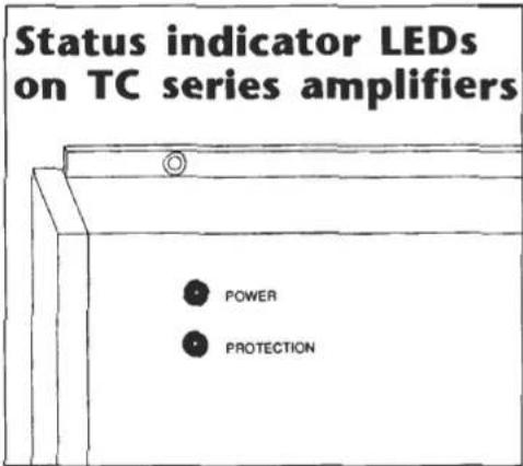
The POWER LED turns on when 10–15.5V is present at the battery (+) terminal and the REMOTE-ON terminal. This indicates that the amplifier is functional.
The PROTECTION LED turns on if any of the following conditions are present:
• If the speaker wires are shorted.
- If the speaker impedance drops below approximately 1.5 ohms in stereo or 3 ohms in bridged mono.
- If the amplifier overheats and the thermal protection circuitry is activated.
Note: The TC Series amplifiers will turn off in under- or over-voltage conditions and will not leak DC voltage (which could damage speaker voice coils).
Application drawings
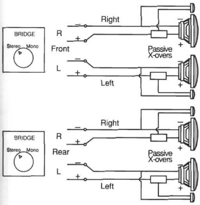
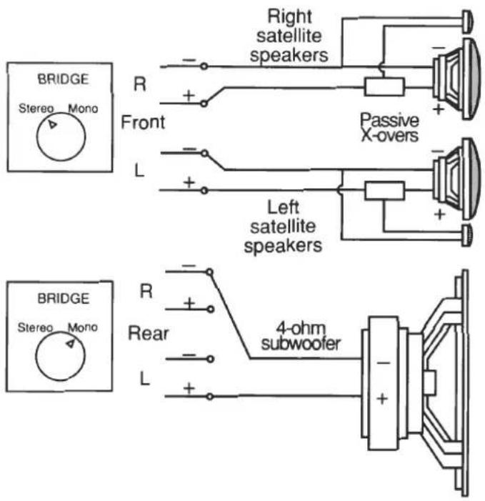
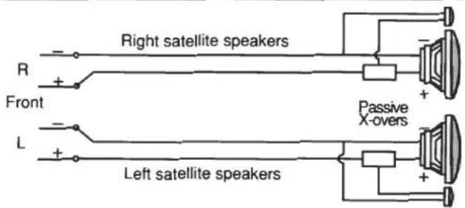
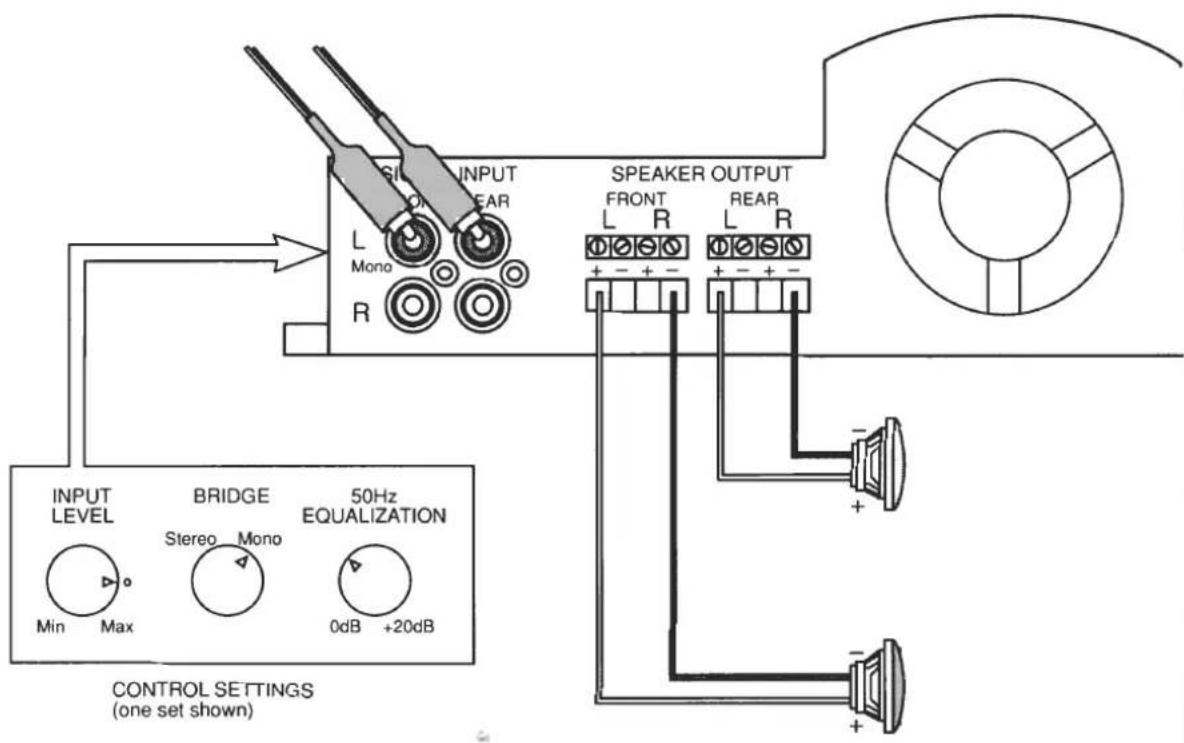
This section provides schematic wiring diagrams and other drawings for many common system configurations. For descriptions of these configurations, see "System configurations," earlier in this manual. Each configuration requires a particular setting of the "Bridge" control (which is noted in the drawing); see the section titled, "Controls and operation" for more information about control settings. The crossover points shown in some illustrations are for example only and may not suit your particular application.
TC600 or TC300 standard stereo operation
TC600 or TC300
bridged-mono
operation
TC304 four-channel (dual-stereo) operation
TC304 true discrete three-channel operation
TC304 simultaneous bridged-mono/stereo in four-channel discrete mode
TC304 two-channel (dual bridged-mono) operation
(See illustration on next page also.)
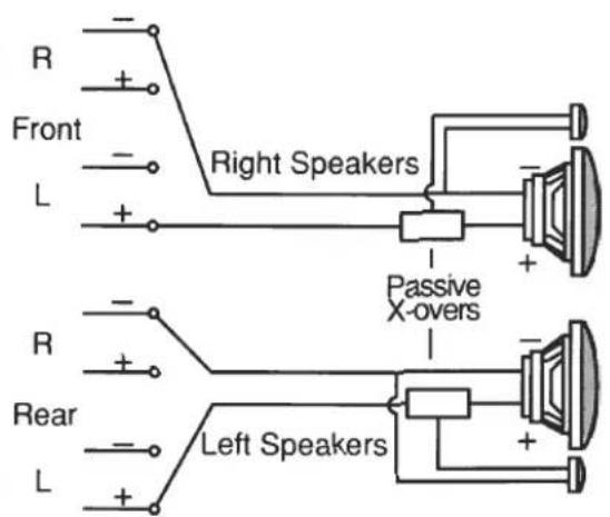
OR
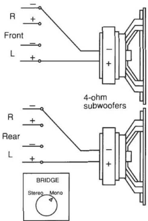
TC304 two-channel (dual bridged-mono) operation
TC304 dual simultaneous bridged-mono/stereo operation in four-channel mode with non-fading front-to-rear balance
Series-Parallel and minimum impedance speaker connection
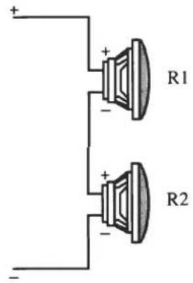
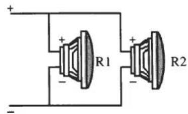
Series-Parallel combinations of loudspeakers are used to acoustically balance systems. In addition, by using different combinations of series and parallel connections, you can achieve optimum operating impedances, which will allow you to extract maximum power from a given amplifier. You can also use these combinations as a way of protecting your speakers from being overdriven and damaged by the amplifier.
TC Series amplifiers provide their highest power at their minimum impedance loading of 2 ohms stereo or 4 ohms bridged mono. If your amplifier is subjected to impedances in any given frequency range that are lower than these nominal impedance minimums, your amplifier will eventually activate its protection mode and temporarily shut off. To determine minimum impedances, consider the combined impedances of all speakers operating in each frequency range.
Series
R1 + R2 = combined impedance.
For example, if R1 and R2 are both 4-ohm speakers, the combined impedance is: 4 + 4 = 8 ohms.
Parallel
$$ \frac {\mathrm{R1XR2}}{\mathrm{R1+R2}} = \text { combined impedance } $$
For example, if R1 and R2 are both 4-ohm speakers, the combined impedance is:
$$ \frac {4 \mathrm{X} 4}{4 + 4} = \frac {1 6}{8} = 2 \mathrm{ohms} $$
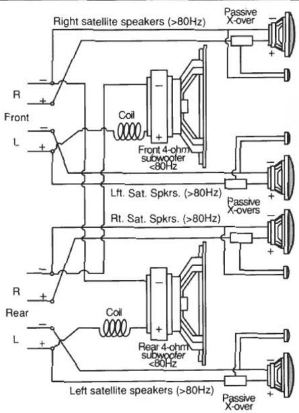
The TC Series simultaneous bridged mono/stereo satellite operation demonstrates this minimum impedance concept, as these diagrams illustrate:
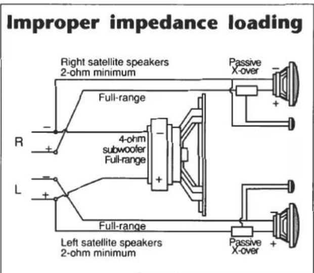
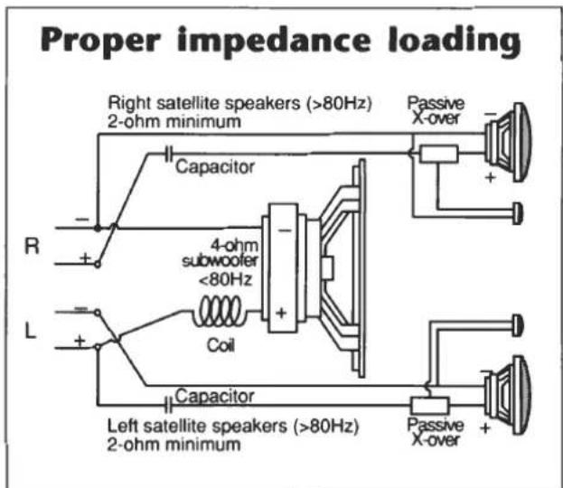
If the left and right satellite speakers are 2 ohms and operated full-range, the amplifier would see a proper impedance load. However, if a 4 ohm subwoofer is additionally bridged across the left and right channels without a crossover filter, the amplifier will now see 1 ohm per channel in the combined woofer/satellite operating range, thereby eventually triggering the amplifier's protection mode (a 4-ohm bridged load looks like a 2-ohm load per channel to an amplifier).
Separating the operating ranges of the satellites and woofer with a passive crossover filter as shown in the above example will provide a proper minimum impedance load of 2 ohms stereo above 80Hz and 4 ohms bridged mono below 80Hz.
Troubleshooting checklist
Most of the problems experienced by customers are due to installation or operational problems. If your amplifier does not operate as expected, first check the items in this checklist. Also check other related components, such as head units, equalizers, crossovers, speakers, and other electrical equipment used with your amplifier. If you still have difficulties in normal operation, please contact an authorized Harman Kardon service center.
| Problem | Cause | Remedy |
| No sound. Power LED does not light. | No 12V (positive) at B+ terminal.Remote-on terminal not receiving +12V from head unit.Power ground connection(s) (negative) is poor.Car battery voltage is below 9V or above 16V. | Check power connections and fuses.Check remote-on connections.Check power grounds.Check condition of car battery and charging system. |
| No sound. Power and Protect LEDs are lit immediately upon turn-on. | Speaker or speaker wire shorted. | Check speaker wiring and speakers. |
| Amplifier plays for a short time, then no sound. Power and Protect LEDs are on. | Fan openings restricted or in “dead air.”Combined minimum speaker impedance is too low. | Ensure clear air paths in and out of fan openings.Reconfigure speakers and crossovers for minimum impedance load (see “Series-Parallel and minimum impedance speaker connection”). |
| Amp plays clearly but not loud enough at high head unit volume control settings. | ·Input control adjusted too low. | ·Readjust input control (see “Controls and operation”). |
| Amp plays clearly at low to moderate head unit volume control settings, but sound distorts at high volumes. | ·Speakers are not rated for higher power and cannot handle the amplifier’s output. | ·Upgrade speakers to a model that can handle higher power and/or readjust INPUT control counterclockwise. |
| ·Input control is adjusted too high and amplifier is clipping. | ·Readjust input level control counterclockwise to eliminate clipping (see “Controls and operation”). |
Fan reversal for multiple amplifier installations
In some installations, it may be desirable to mount two or more TC Series amplifiers one after another in a line. You can reverse the fan in any amplifier to reverse the direction of air flow through the tunnel; this enables you to prevent the warm air from the first amp from being vented into the tunnel of the second amp, and so on.
From the factory, the fan pulls air through the tunnel and exhausts the warm air at the fan end when music is playing. This direction of air circulation provides the best cooling for a TC Series amplifier. Leave the amplifier(s) that will be driven the hardest (usually the bass frequencies) in the factory configuration, and only reverse the cooling direction on the amplifiers with the lighter load. Note: In the factory configuration, the fan hub label is positioned toward the outside of the amplifier.
To reverse the direction of the air flow, the fan itself must be reversed in its mounting (the fan is electrically controlled, and simply reversing power to the fan will not change its direction). Contact any authorized Harman Kardon installer or service center to perform the fan reversal, and take this manual with you.
To reverse the direction of air flow through the tunnel:
-
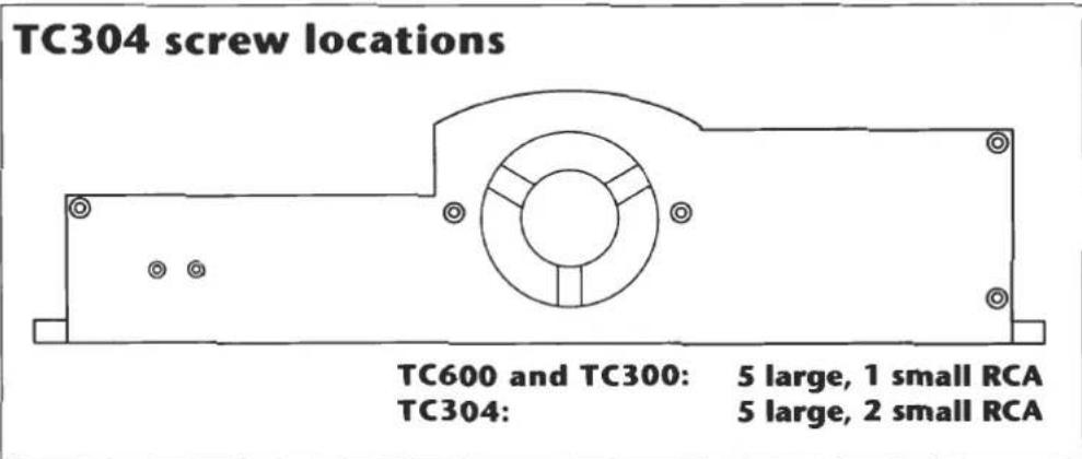
Carefully remove the screws attaching the fan end cap of the amplifier (see illustration for location of screws).
-
Gently remove the end cap just far enough to allow removal of the fan from its mounting pins in the end cap. DO NOT REMOVE THE WIRES.
-
Flip the fan assembly 180° so that it faces in the opposite direction. Make sure the rubber insulation pads are still in place on both sides of the fan. The wires are attached to the circuit board, and the fan stays with the end cap, so be careful not to stretch or damage the wires.
-
Replace the end cap assembly and screws. DO NOT OVERTIGHTEN THE SCREWS.
Specifications
| TC600 | TC300 | TC304 | |
| Power output, RMS | 600 watts continuous power200W X 2 channels @ 4ohms300W X 2 channels @ 2ohms600W X 1 channel @ 4ohms | 300 watts continuous power100W X 2 channels @ 4ohms150W X 2 channels @ 2ohms300W X 1 channel @ 4ohms | 300 watts continuous power50W X 4 channels @ 4 ohms75W X 4 channels @ 2ohms50W X 2 channels @ 4ohms+150W X 1 channel @ 4ohms75W X 2 channels @ 2ohms+150W X 1 channel @ 4ohms150W X 2 channels @ 4ohms |
| HCC (High Instantaneous Current Capability) | ±100A | ±50A | ±50A |
| THD (4ohms/2ohms) | No more than 0.1%/0.2% | No more than 0.1%/0.2% | No more than 0.1%/0.2% |
| Negative Feedback | 25dB | 25dB | 25dB |
| Frequency response | 10Hz to 100,000Hz +0, -3dB | 10Hz to 100,000Hz +0, -3dB | 10Hz to 100,000Hz +0, -3dB |
| Signal-to-noise ratio (referred to rated power) | 100dB | 100dB | 100dB |
| Input sensitivityContinuously variable (line-level to high-level) | 0.25V to 2.5V | 0.25V to 2.5V | 0.25V to 2.5V |
| Input impedanceCenter pin connector (+)Outside shield (-) | 22kohms22kohms | 22kohms22kohms | 22kohms22kohms |
| Power supply | DC +14.4V (9~16V usable), negative ground | DC +14.4V (9~16V usable), negative ground | DC +14.4V (9~16V usable), negative ground |
| Typical current requirementsAt idleFull-power music signalFull-power sine wave | 7.5A20A (4ohms/channel)30A (2ohms/channel)60A (4ohms/channel)90A (2ohms/channel) | 4.0A10A (4ohms/channel)15A (2ohms/channel)30A (4ohms/channel)45A (2ohms/channel) | 4.0A10A (4ohms/channel)15A (2ohms/channel)30A (4ohms/channel)45A (2ohms/channel) |
| Dimensions (L X W X H) | 16-5/8" X 12-7/8" X 3-1/4"422 X 327 X 83mm | 14-5/8" X 12-7/8" X 3-1/4"371 X 327 X 83mm | 16-5/8" X 12-7/8" X 3-1/4"422 X 327 X 83mm |
| Weight | 14lbs. 12oz. (6.7kg) | 13lbs. 0oz. (5.9kg) | 14lbs. 12oz. (6.7kg) |
All specifications and features subject to change without notice.
harman/kardon • 240 Crossways Park West • Woodbury • New York • 11797
HKTCOMUS90
- TC600
- TC300
- TC304
- Table of Contents
- Harman Kardon design philosophy
- • HCC (High-Instantaneous Current Capability)
- - Bridgeable
- • Ultrawidebandwidth
- - Low negative feedback
- • Fully discrete circuitry
- TC600, TC300, and TC304 Features
- Designed and manufactured in the U.S.A.
- Two-stage music-linked cooling fan speed
- Reversible fan
- Simultaneous stereo plus bridged mono operation
- 50Hz boost
- Fully regulated high-capacity power supply
- B+ and remote-on power noise filtering
- Balanced differential variable-gain inputs
- Introduction
- Important
- Warranty card
- Caution
- Installation precautions
- Charging system considerations
- Mounting location
- System configurations
- Low-level input to amplifier
- High-level input to amplifier
- Normal stereo or four-channel full-range operation
- Dedicated full-range bridged amplifier operation
- Bridged amplifier operation with electronic crossover
- Simultaneous bridged-mono/ stereo satellite operation
- 4,3,2 operation using the TC304 four-channel amplifier
- Connecting the TC-series amplifier
- General information
- Connection tips:
- Wire-routing tips:
- Power connections
- 12V Positive (B+) connection
- 12V Ground (B-) connection
- TC300 or TC304
- Remote-on
- Audio input connections
- Low-level (preamp-level) connections
- High-level (speaker-level) connections
- Speaker output connections
- Controls and operation
- Bridged mono/stereo switch
- Input sensitivity control
- For standard low-level (preamp-level) inputs:
- For nonstandard low-level (preamp-level) and high-level (speaker-level) inputs:
- 50Hz boost equalization
- Indicator LEDs
- Application drawings
- Series-Parallel and minimum impedance speaker connection
- Series
- Parallel
- Troubleshooting checklist
- Fan reversal for multiple amplifier installations
Brand : HARMAN KARDON
Model : TC304
Category : Car radio