
AXIR - Loudspeaker Audac - Free user manual and instructions
Find the device manual for free AXIR Audac in PDF.


| Product Type | Design Column Speaker |
| Dimensions (W x H x D) | 70 x 1005 x 105 mm |
| Weight | 4.00 kg |
| RMS Power | 120 W |
| Max Power | 240 W |
| Impedance | 6 Ohm |
| Frequency Response (-3 dB) | 100 Hz - 17 kHz |
| Sound Pressure Level (1W/1m) | 86 dB |
| Maximum SPL (1m @ 100V) | 106 dB |
| Horizontal Coverage | 170° |
| Drivers | 12 x 2 inch |
| Construction | Aluminum housing |
| Front Finish | Aluminum grille |
| Line Transformer Power Taps (100V) | 2 x 20W, 2 x 10W, 2 x 5W, 2 x 2.5W |
| Color Options | White (RAL 9010), Black (RAL 9005) |
| Mounting | Wall bracket included |
| Special Feature | Individual power tap selectors for upper and lower sections |
| Operating Modes | 100V line or low impedance (6 Ohm) |
Frequently Asked Questions - AXIR Audac
User questions about AXIR Audac
0 question about this device. Answer the ones you know or ask your own.
Ask a new question about this device
Download the instructions for your Loudspeaker in PDF format for free! Find your manual AXIR - Audac and take your electronic device back in hand. On this page are published all the documents necessary for the use of your device. AXIR by Audac.
USER MANUAL AXIR Audac
AXIR Design Column speaker
User Manual & Installation Guid
AUDAC PROFESSIONAL AUDIO EQUIPMENT
User Manual & Installation Guide
© AUDAC
http://www.audac.eu
info@audac.eu
Index
INTRODUCTION 2
SAFETY REQUIREMENTS....3
WARNING - CAUTION....3
INSTALLATION....4
DETERMINING LISTENING AREA AND MOUNTING HEIGHT 4
OTHER POINT TO PAY ATTENTION TO 7
CREATE SPECIFIC POLAR PATTERNS 8
CONNECTING THE AXIR 9
CONNECTIONS 9
LINE TRANSFORMER POWER TAPS....10
CONVERT FOR USE IN LOW IMPEDANCE APPLICATIONS....11
ADDITIONAL INFORMATION AXIR 12
TECHNICAL SPECIFICATIONS.... 12
POLAR PATTERNS 13
PERSONAL NOTES 14
Introduction
This introduction briefly describes the possibilities of the AXIR design column speaker..
The AXIR was designed to meet professional demands en proves its worth in auditoria, conference rooms, meeting rooms, churches,... any place that requires a great flexibility in positioning and tuning, ass well as state-of-the-art audio quality and design.
Key features:
- High-quality 2 inch speakers, especially designed by AUDAC, make the AXIR suitable for music and speech.
- 4 selectable output power taps for 100V operation mode.
- Ultra lightweight design and strong aluminum housing.
- Especially designed metal wall brackets included
- Two separate power tap selectors for upper and lower speaker units allow you to create a specific polar pattern. It can accommodate virtually any acoustic situation.
Chapter 1
Warning
- Only use the correct amplifier output voltage and impedance, exceeding these limits could cause damage, fire or other failures.
- Only install the speaker on surfaces that can accommodate the weight of the speaker and the mounting bracket.
- Don't use any other mounting method than specified.
- Attach a safety wire to the speaker when it's mounted high up. This ensures that the speaker can't fall down in any case.
- Avoid mounting the speaker in locations exposed to constant vibrations. The mounting bracket can be damaged by excessive vibration, potentially causing the speaker to fall down.
Caution
- Avoid electric shocks: turn off the amplifier when connecting the speaker.
- Don't operate the speaker for an extended period of time at distorted sound. This can cause irreparable damage to the speaker.
- Don't stand or sit on it, nor hang down from the speaker as this may cause it to fall down or drop.
Chapter 2
Installation
To achieve the best possible intelligibility and sound quality with a column speaker, there has to be paid extra attention to the proper mounting of the speaker.
The dimensions of the desired listening area has to be determined where out the correct mounting height and angle can be derived.
A step by step installation procedure describes the method to determine the mounting height and angle for the AXIR.
DETERMINING LISTENING AREA AND MOUNTING HEIGHT
STEP 1:
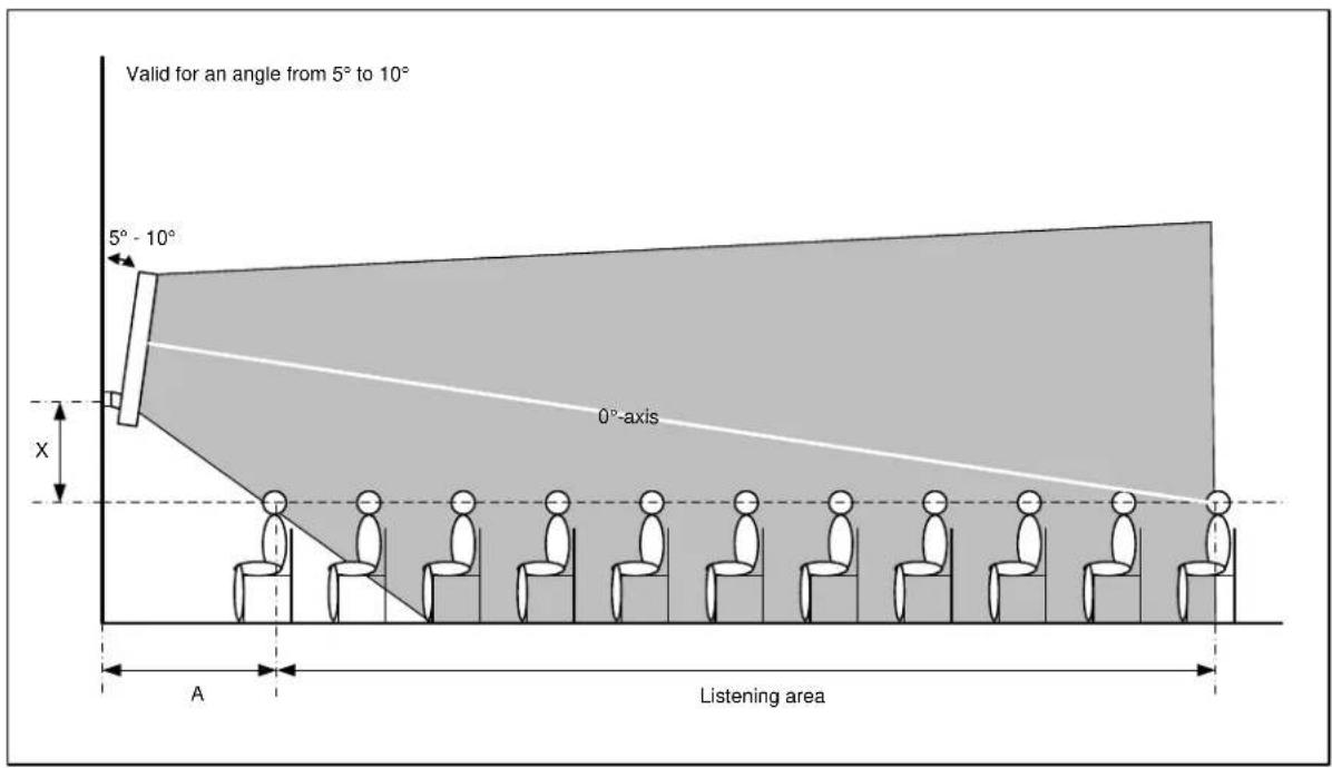
Determine the dimensions of the desired Listening Area. This is a horizontal plane at the level of the listeners cars. Refer to the dashed line in following figure.

STEP 2:
After the listening area, determine at which angle the loudspeaker array has to be mounted. The AXIR column speaker was designed to aim the sound just above the heads of the listeners, and it is recommended not to exceed an angle of 6^ . There are two different approaches to determine the mounting angle, each with specific advantages and disadvantages. Which approach you choose, depends on what you want to achieve: a maximum listening area or a minimal variation in sound pressure level.
- Approach 1: Maximum listening area
When a large listening area is desired, an angle of around 3^ is recommended. When you move away from the loudspeaker, the sound pressure level will be decreased. This decrease depends on the reverberation of the room in which the speaker is placed. If you want the high tones to be clearly audible, make sure the listener is able to see the loudspeaker array.

- Approach 2: Minimal variation in sound pressure level
When a minimal variation in sound pressure level is desired, an angle of 5^ is ideal for this purpose. The size of the total listening area becomes in comparison with the previous approach, smaller. The space nearby the loudspeaker ‘A’ does not belong to the listening area.
(Diagram 1 shows the relationship between ‘Λ’ and the mounting height of the loudspeaker when using an angle of 5°)

line
| Distance A (m) | Height X between listening area and speaker (cm) | | -------------- | ----------------------------------------------- | | 0 | 0 | | 32 | 20 | | 51 | 40 | | 52 | 60 | | 53 | 80 | | 54 | 100 |STEP 3:
When you've chosen one of the above approaches to determine your mounting angle, you proceed by determining the mounting height. This height is determined by aiming the 0^ axis of the AXIR in the desired position, precisely above the ear level of the listener who's the furthest away from the speaker. This can be adjusted by mounting the loudspeaker higher and lower on the wall.
STEP 4:
When you've determined the mounting angle and height, you can start installing the speaker.
OTHER POINTS TO PAY ATTENTION TO:
While mounting a column speaker, there are still some other points where has to be paid attention to.
- Make sure that the loudspeaker array is always visible for everyone in the listening area, to ensure a good audibility of the high tones. High tones can be compared with light. When something is between the observer and the light source, the observer can't see the light source at it's full power, this is what we call shadow.
For high tones, this is the same issue. When someone is standing between the listener and the loudspeaker, the listener is located in the sound shadow. The sound shadow will be experienced as a reduction of high tones.
- When the loudspeaker is installed at a very small angle, a large listening area can be reached. Depending on the amount of reverberation in the room and the sound shadow, the speech intelligibility on a far position may be low. In this situation, it is recommended to use more loudspeaker arrays to split the listening area.
- When you move further than the maximum position of the listening area (further than the maximum distance of the loudspeaker array), only the sound pressure level will decrease. There will be almost no tone height variation. The decreasing factor of the sound pressure level depends strongly on the reverberation of the room.
- When you are located too close to the loudspeaker array (closer than the minimum distance) a decline of the high tones will occur very soon.
- Because the loudspeakers are designed to beam the sound just above the listeners ears, it's better to mount the speakers not to high above the listening area.
- When you want to determine where exactly the edges of the listening area are located in your situation, you have to do a practical test at this location. This is a job for an experienced listener with well-trained ears. Put pink noise through the loudspeaker array, and reduce the lower tones for this test because they do not contribute to speech intelligibility. Walk around in the listening area and pay attention to the high tones. The places where the high tones decrease rapidly are the edges of the listening area.
CREATE SPECIFIC POLAR PATTERNS
The AXIR contains two individual speaker sections whose power can be individually set between 20W, 10W, 5W and 2.5W. The desired power taps can be selected by a recessed adjuster screw behind the speakers cover.
This allows us to set the total speaker power between 5W and 40W, but it also gives the possibility to create a specific polar pattern.
By adjusting the upper and lower power taps independent from each other, the sound transfer length can be adapted to each specific situation.
Following figure shows an example of a situation where by means of the two individual power tap selectors a specific polar pattern can be realized. The lower speaker section is set to a lower power than the upper speaker section. By correct focusing of the speaker the sound transfer length of the speaker can be adapted to each specific situation.

Chapter 3
Connecting the AXIR
CONNECTIONS:
At the back of the AXIR is a 3 pole euro terminal block connector provided to connect the amplifier with the AXIR column speaker.
Depending of the speaker is used in 100V applications or low impedance applications, the wiring diagram is different. (This is done for protection reasons of the speaker) For 100V applications are the two outer pins used (Pin 1 & Pin 3) and for low impedance applications is the centre pin and one outer pin used (Pin 1 & Pin 2).

Warning: Notice the polarity markings when wiring the loudspeaker cables.
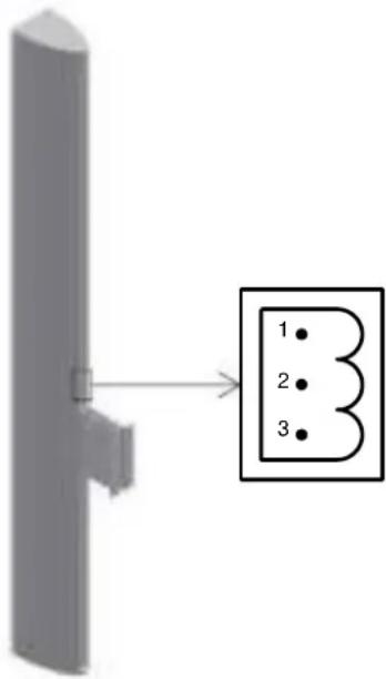
| PIN | 100V | 6 Ω |
| 1 | - | - |
| 2 | N.C. | + |
| 3 | + | N.C. |

Warning: The AXIR is default set for use in 100V applications, for use in low dance applications, the internal switches of the speaker must be switched.
LINE TRANSFORMER POWER TAPS:
To adjust the power taps of the speaker, the front cover plate with the AUDAC logo should be removed very carefully. This is best done by carefully sticking a flat object under the cover plate (e.g. a small flat screwdriver). The cover plate is coming loose, without performing large forces.
After the cover plate is removed, the two power tap selector switches are visible.
The power taps can be set to 4 different powers for each individual speaker section. Adjust the power taps by using a screwdriver to turn the rotary switch.
- 20W
- 10W
- 5W
- 25W

CONVERT FOR USE IN LOW IMPEDANCE APPLICATIONS:
⚠️Notice: Only perform this procedure if the speaker should be used in low impedance applications.
For use in low impedance applications, the internal switches of the speaker must be switched.
To reach the internal switches, the front cover plate with the AUDAC logo should be removed very carefully. This is best done by carefully sticking a flat object under the cover plate (e.g. a small flat screwdriver). The cover plate is coming loose, without performing large forces.
After the cover plate is removed, the two power tap selector switches are visible.

To reach the internal switches, the plate with the two power tap selector switches should be removed. This can be done by loosening the 6 Phillips screws whereby it is attached.
Once these screws are loose, the plate can be carefully removed out of the speaker. (Be careful with the wiring inside the speaker)
Then you will see that there are two switches provided at the side of this plate. These switches are meant to convert the speaker for use in 100V or low impedance applications.
Set the switch to 100V for 100V applications, and set the switch to 6Ω for low impedance applications.
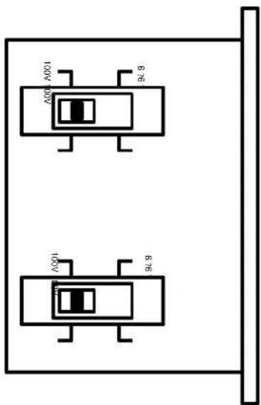
Warning: Make sure that the two switches are always both in the same position. Make sure that it never occurs that one of them is on 100V and the other is in 6Ω position.
Chapter 4
Additional information AXIR
TECHNICAL SPECIFICATIONS
| RMS Power | 120 W |
| Max Power | 240 W |
| Impedance | 6 Ohm |
| Line Transformer power tappings | 2 x 500 Ohm / 2 x 20 W2 x 1000 Ohm / 2 x 10 W2 x 2000 Ohm / 2 x 5 W2 x 4000 Ohm / 2 x 2,5 W |
| Sound pressure 1W / 1m | 86 dB |
| Sound pressure max W / 1 m @ 100 V | 106 dB |
| Frequency response (-3 dB) | 100 Hz - 17 kHz |
| Horizontal coverage | 170 ° |
| Construction | Aluminium |
| Front finish | Aluminium grille |
| Drivers | 12 x 2 inch |
| Dimensions (W x H x D) | 70 x 1005 x 105 mm |
| Weight | 4.00 Kg |
| Accessories included | Wall bracket |
| Colors | White RAL 9010Black RAL 9005 |
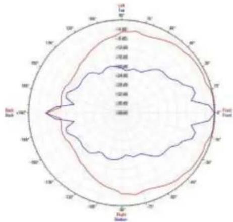
Polar patterns

radar
| Angle | Value | |---|---| | 0° | -100 | | 45° | -80 | | 90° | -60 | | 135° | -40 | | 180° | -20 | | 225° | 0 | | 270° | 20 | | 315° | 40 | | 360° | 60 | | 405° | 80 | | 450° | 100 | | 505° | 80 | | 550° | 60 | | 605° | 40 | | 650° | 20 | | 705° | 0 | | 750° | -20 | | 805° | -40 | | 850° | -60 | | 905° | -80 | | 950° | -100 | | 1005° | -80 | | 1050° | -60 | | 1105° | -40 | | 1150° | -20 | | 1205° | 0 | | 1250° | 20 | | 1305° | 40 | | 1350° | 60 | | 1405° | 80 | | 1450° | 100 | | 1505° | 80 | | 1550° | 60 | | 1605° | 40 | | 1650° | 20 | | 1705° | 0 | | 1750° | -20 | | 1805° | -40 | | 1850° | -60 | | 1905° | -80 | | 2050° | -100 | | 2105° | -80 | | 2150° | -60 | | 2205° | -40 | | 2250° | -20 | | 2305° | 0 | | 2350° | 20 | | 2405° | 40 | | 2450° | 60 | | 2505° | 80 | | 2550° | 100 | | 2605° | 80 | | 2650° | 60 | | 2705° | 40 | | 2750° | 20 | | 2805° | 0 | | 2850° | -20 | | 2905° | -40 | | 3050° | -60 | | 3105° | -80 | | 3150° | -100 | | 3205° | -80 | | 3250° | -60 | | 3305° | -40 | | 3350° | -20 | | 3405° | 0 | | 3450° | 20 | | 3505° | 40 | | 3550° | 60 | | 3605° | 80 | | 3650° | 100 | The chart displays a radar or contour plot with two data series plotted against angular positions in degrees. The first series is represented by a red line, and the second series by a blue line. The data points are labeled on the chart as follows: 'Left Point' at approximately -1.2, 'Right Point' at approximately +1.2. The chart is divided into four quadrants (Top, Bottom, Left, Right) based on their respective angular positions. The values for each series are explicitly labeled on the chart.1000 Hz
2000 Hz

radar
| Direction | Value | | --------- | ----- | | Top Left | 120 | | Top Right | 115 | | Bottom Left | 110 | | Bottom Right | 105 | | Bottom Left | 95 | | Bottom Right | 90 | | Bottom Left | 85 | | Bottom Right | 80 | | Bottom Left | 75 | | Bottom Right | 70 | | Bottom Left | 65 | | Bottom Right | 60 | | Bottom Left | 55 | | Bottom Right | 50 | | Bottom Left | 45 | | Bottom Right | 40 | | Bottom Left | 35 | | Bottom Right | 30 | | Bottom Left | 25 | | Bottom Right | 20 | | Bottom Left | 15 | | Bottom Right | 10 | | Bottom Left | 5 | | Bottom Right | 0 |4000 Hz

radar
| Direction | Value | | --------- | ----- | | Left Top | 150 | | Left Bottom | 140 | | Right Top | 160 | | Right Bottom | 155 |8000 Hz
— Horizontal
— Vertical
Personal notes


- User Manual & Installation Guid
- User Manual & Installation Guide
- Index
- Introduction
- Chapter 1
- Warning
- Caution
- Chapter 2
- Installation
- DETERMINING LISTENING AREA AND MOUNTING HEIGHT
- STEP 1:
- STEP 2:
- - Approach 1: Maximum listening area
- - Approach 2: Minimal variation in sound pressure level
- STEP 3:
- STEP 4:
- OTHER POINTS TO PAY ATTENTION TO:
- CREATE SPECIFIC POLAR PATTERNS
- Chapter 3
- Connecting the AXIR
- CONNECTIONS:
- LINE TRANSFORMER POWER TAPS:
- CONVERT FOR USE IN LOW IMPEDANCE APPLICATIONS:
- Chapter 4
- Additional information AXIR
- TECHNICAL SPECIFICATIONS
- Personal notes
Brand : Audac
Model : AXIR
Category : Loudspeaker