
KYRA6 - Loudspeaker Audac - Free user manual and instructions
Find the device manual for free KYRA6 Audac in PDF.

| Product Type | Design Column Speaker |
| Brand | Audac |
| Model | KYRA6 |
| Drivers | 6 x 2" Alu Cone Full Range |
| Max Power | 120 W |
| RMS Power | 60 W |
| Nominal Impedance | 12 Ω |
| Line Transformer Taps (100V/70V) | 250 Ω (70V/20W), 500 Ω (100V/20W, 70V/10W), 1 kΩ (100V/10W, 70V/5W), 2 kΩ (100V/5W, 70V/2.5W) |
| Cross-Over Network | Passive Built-In (Low-Cut Filter) |
| Connectors | 3-Pin Terminal Block (5.08 mm) |
| Mounting | 2-Way Revolving Metal Bracket (included) |
| Construction | Aluminum Extrusion + Plastic Caps |
| Front Finish | Fine Perforated Steel Grill |
| Ingress Protection | IP3x |
| Operation Temperature Range | -20°C to +50°C |
| Tilt Angle | 0° to 13° Downward |
| Pan Angle | 0° to 42° Left and Right |
| Dimensions (W x H x D) excl. Bracket | 70 x 546 x 101 mm |
| Weight | 2.26 kg |
| Available Colors | White (RAL9003) or Black (RAL9005) |
| Included Accessories | 3-Pin Terminal Block Connector, 2-Way Revolving Metal Bracket, Cable Guiding Accessories |
| Recommended Use | Indoor Only |
| Maintenance | Clean with Dry Cloth |
| Safety Note | Do not expose to rain or moisture; use correct amplifier output voltage |
Frequently Asked Questions - KYRA6 Audac
User questions about KYRA6 Audac
0 question about this device. Answer the ones you know or ask your own.
Ask a new question about this device
Download the instructions for your Loudspeaker in PDF format for free! Find your manual KYRA6 - Audac and take your electronic device back in hand. On this page are published all the documents necessary for the use of your device. KYRA6 by Audac.
USER MANUAL KYRA6 Audac
natural_image
Illustration of a tall, textured vertical speaker with a small square button at the base (no text or symbols)
www.audac.eu
Introduction
Design column speakers
The KYRA column speakers range is the elegant result of research in the field of phased array acoustics. The selection of the highest quality materials including aluminum cone 2" drivers guarantee an extraordinary detail and clarity for music and speech, which is uncommon for any kind of column speaker available from the market. It makes them perfectly lend themselves to a wide variety of applications in acoustic difficult environments such as churches, auditoriums, presentation and meeting rooms where audibility and intelligibility of music and speech have the highest importance.
They are housed in slim and elegant constructed enclosures made out of aluminum materials and finished with finely perforated grilles. An included mounting bracket with minimum distance to the wall allows swivelling and down—tilting for perfect directional placement.
They come in three different models (KYRA6, KYRA12 and KYRA24) in terms of length and driver count, all are constructed with the identical high-quality aluminum cone full range drivers. Each of them with their specific pattern in terms of dispersion and throw distance. They offer solutions for uniform acoustic performance in any type of system in reverberant venues, while reducing echo and microphone feedback to optimize the intelligibility of music & speech.
A multi-tapping line transformer allows them to be connected to 70V/100V public address systems with various power tapping settings, while connections in low impedance (12Ω) systems are also possible.
Precautions
READ FOLLOWING INSTRUCTIONS FOR YOUR OWN SAFETY
- ALWAYS KEEP THESE INSTRUCTIONS FOR FUTURE REFERENCE. NEVER THROW THEM AWAY
• ALWAYS HANDLE THIS UNIT WITH CARE - CLEAN ONLY WITH DRY CLOTH
• HEED ALL WARNINGS AND FOLLOW ALL INSTRUCTIONS - NEVER EXPOSE THIS EQUIPMENT TO RAIN, MOISTURE, ANY DRIPPING OR SPLASHING LIQUID. AND NEVER PLACE AN OBJECT FILLED WITH LIQUID ON TOP OF THIS DEVICE
- DO NOT INSTALL THIS UNIT NEAR ANY HEAT SOURCES SUCH AS RADIATORS OR OTHER APPARATUS THAT PRODUCE HEAT
- DO NOT PLACE THIS UNIT IN ENVIRONMENTS WITH A HIGH LEVEL OF DUST, HEAT, MOISTURE OR VIBRATION
- THIS UNIT IS DEVELOPED FOR INDOOR USE ONLY. DO NOT USE IT OUTDOORS
- ONLY USE ATTACHMENTS & ACCESSORIES SPECIFIED BY THE MANUFACTURER.
- ONLY INSTALL THE SPEAKER IN LOCATIONS THAT CAN STRUCTURALLY SUPPORT THE WEIGHT OF THE SPEAKER. IGNORING THIS CAN BRING THE SPEAKER DOWN.
- DO NOT USE ANY OTHER METHOD THAN SPECIFIED TO MOUNT THE SPEAKER. IF EXTREME FORCE IS APPLIED TO THE SPEAKER, IT COULD FALL DOWN
- ATTACH A SAFETY WIRE TO THE SPEAKER WHEN IT IS MOUNTED HIGH UP. ONLY USE INDUSTRY—ACCEPTED RIGGING TOOLS AND METHODS
- CAREFULLY CHECK THE UNIT'S CONDITION AFTER UNPACKING. IF THERE IS ANY DAMAGE TO THE CARTON BOX OR THE UNIT ITSELF, INFORM YOUR VENDOR IMMEDIATELY.
CAUTION
• USE CABLES OF THE RIGHT GAUGE TO CONNECT THE LOUDSPEAKER
- USE CABLES WITH CLEAR COLOR CODING INDICATING THE POLARITY AND MAINTAIN THE SAME POLARITY THROUGHOUT THE WHOLE SYSTEM.
- ONLY USE THE CORRECT AMPLIFIER OUTPUT VOLTAGE AND IMPEDANCE. EXCEEDING THESE LIMITS COULD CAUSE FIRE OR OTHER FAILURES. AVOID EXPLOSIONS: DO NOT USE THE SPEAKER AROUND GASOLINE, THINNER OR OTHER COMBUSTIBLES
- AVOID ELECTRIC SHOCKS: SWITCH OFF THE AMPLIFIER WHEN CONNECTING THE LOUDSPEAKER
- DO NOT USE THE LOUDSPEAKER FOR AN EXTENDED PERIOD OF TIME AT DISTORTED SOUND. THIS COULD CAUSE PERMANENT DAMAGE.

natural_image
Three white icons on a gray background: a raised fist, a stylized 'CE' symbol, and a crossed-out device with crossbar (no text or symbols)CAUTION - SERVICING
This product contains no user serviceable parts. Refer all servicing to qualified service personnel. Do not perform any servicing (unless you are qualified to do so.)
EC DECLARATION OF CONFORMITY
This product conforms to all the essential requirements and further relevant specifications described in following directives: 2014/30/EU (EMC) and 2014/35/EU (LVD)
WASTE ELECTRICAL AND ELECTRONIC EQUIPMENT (WEEE)
The WEEE marking indicates that this product should not be disposed with regular household waste at the end of its product life. This regulation is created to protect both the environment and human health.
This product is developed and manufactured with high quality materials and components which can be recycled and/or reused. Please dispose this product to your local collection point or recycling centre for electrical and electronic waste. This will make to sure that it will be recycled on an environmentally friendly manner, and will help to protect the environment in which we all live.
Installing the KYRA
Mounting the speaker
Every KYRA speaker comes delivered with a two-way revolving bracket, making it possible to install the speaker at each position and focusing it into the desired direction. The metal constructed bracket ensures a solid and secure mounting of the loudspeaker to any possible location.

natural_image
Technical line drawing of a door panel assembly with exploded and assembled views (no text or symbols)It consists of two different parts, whereof the first part should be installed to the rear side of the loudspeaker. It can be assembled on different heights on the rear of the speaker, depending on the mounting possibilities and required installation height. It is fixated to the loudspeaker cabinet by inserting the 2 supplied mounting screws into the pre-drilled and threaded holes at the back of the speaker cabinet.
The second part is a wall plate which has to be fixed to the wall by at least four screws (preferably six). The type of used fasteners shall be chosen according to the most suitable type for the mounting surface (brick, concrete, wood, ...). The mounting holes are provided according to the positions indicated in the following drawing.
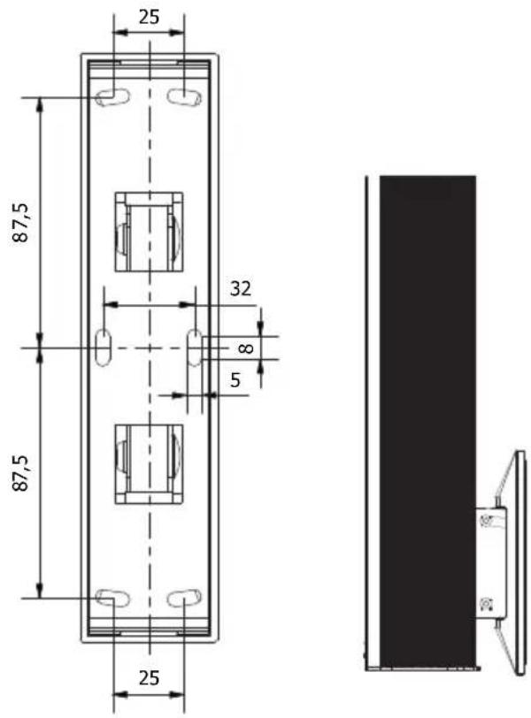
Once both speaker part and wall part are safely attached to their positions, the protective finishing cover can be assembled over the wall plate by clicking it. Afterwards the speaker can be assembled to the wall bracket by bringing both parts together and tightening them through the button head bolt and nuts together through an hex drive key. The upper one can be used for adjusting the tilt-angle of the speaker.
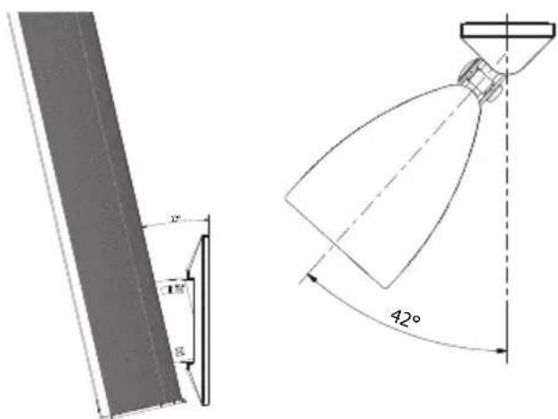
Once installed, the speaker can be can be panned and tilted, focussing the loudspeaker into the desired listening direction. This is useful when the installation height on the wall is limited or the speaker is mounted from the side. The maximum downward tilt is 13^ and the maximum pan in both directions is 42^ .
Connecting the speaker
For connecting the KYRA, the wires coming from the amplifier shall be connected to the 3-pin terminal block connector on the rear of the speaker. Depending whether the speaker will be used in a low impedance (12 Ω) system or a constant voltage (70V/100V) system, the appropriate terminals of the connector should get connected as indicated in the below drawing.
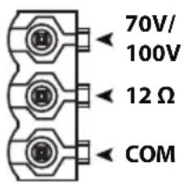
When using in constant voltage 70V/100V systems, the power taps can be adjusted in 4 steps of impedance through a rotary selector switch on the rear side of the unit. The switch can be rotated in 4 positions A, B, C & D. Each position corresponds with a specific impedance / power setting indicated on a label attached to the speaker, and in the table below.

| KYRA6 | KYRA12 | ||||||
| Tapping | 100V | 70V | Imp. | Tapping | 100V | 70V | Imp |
| A | Do not use | 20 W 250 Ω | A | Do not use | 40 W 125 Ω | ||
| B | 20 W 10 | W 500 Ω | B | 40 W 20 | W 250 Ω | ||
| C | 10 W 5 W | 1000 Ω | C | 20 W 10 | W 500 Ω | ||
| D | 5 W 2.5 | W 2000 Ω | D | 10 W 5 W | 1000 Ω | ||
Additional Information
Technical specifications
KYRA6 KYRA12
Max Power 120 Watt 240 Watt
RMS Power 60 Watt 120 Watt
Nominal impedance 12 Ohm 12 Ohm
Line transformer taps
250 Ω - 70V/20W
500 Ω - 100V/20W - 70V/10W
1k Ω - 100V/10W - 70V/5W
2k Ω - 100V/5W - 70V/2.5W
125 Ω - 70V/40W
250 Ω - 100V/40W - 70V/20W
500 Ω - 100V/20W - 70V/10W
1k Ω - 100V/10W - 70V/5W
Drivers
Cross-over network
Connectors
Mounting bracket
Construction
Front finish
Ingress protection
Operation temperature range
6 x 2" Alu cone full range
Passive built-in (low-cut filter)
3-pin Terminal block (5.08 mm)
2-Way revolving metal bracket
Alu extrusion + plastic caps
Fine perforated steel grill
IP3x
-20^ to +50^
12 x 2" Alu cone full range
Passive built-in (low-cut filter)
3-pin Terminal block (5.08 mm)
2-Way revolving metal bracket
Alu extrusion + plastic caps
Fine perforated steel grill
IP3x
-20^ to +50^
Incline angle
Horizontal
0 \~ 42° left & right
0^ 13^ down tilt
0 \~ 42° left & right
0^ 13^ down tilt
Colour
White
KYRA6/W (RAL9003)
KYRA6/B (RAL9005)
KYRA12/W (RAL9003)
KYRA12/B (RAL9005)
Dimensions (W x H x D)
Weight
70 x 546 x 101 mm (excl bracket)
2.26 Kg 4.30 Kg
70 x 1006 x 101 mm (excl bracket)
Packaging
Shipping weight & Volume
Carton box
3.35 Kg - 0.021 Cbm
Carton box
5.8 Kg - 0.032 Cbm
Accessories included
3-pin terminal block connector
2-Way revolving metal bracket
Cable guiding accessories
3-pin terminal block connector
2-Way revolving metal bracket
Cable guiding accessories
Notes
Notes
Notes


- Introduction
- Design column speakers
- Precautions
- READ FOLLOWING INSTRUCTIONS FOR YOUR OWN SAFETY
- CAUTION
- CAUTION - SERVICING
- EC DECLARATION OF CONFORMITY
- WASTE ELECTRICAL AND ELECTRONIC EQUIPMENT (WEEE)
- Installing the KYRA
- Mounting the speaker
- Connecting the speaker
- Additional Information
- Technical specifications
- KYRA6 KYRA12
- Notes
Brand : Audac
Model : KYRA6
Category : Loudspeaker