
507-PQ - Receiver Cabletime - Free user manual and instructions
Find the device manual for free 507-PQ Cabletime in PDF.


| Product Type | Digital TV Receiver |
| Brand | Cabletime |
| Model | 507-PQ |
| Dimensions (W x D x H) | 20 cm x 15 cm x 5 cm |
| Weight | 0.5 kg |
| Power Supply | AC 100-240V, 50/60Hz, DC 5V/1A |
| Power Consumption | 5W (max) |
| Input | RF Antenna (IEC), USB 2.0 |
| Output | HDMI, AV (RCA), Coaxial Audio |
| Supported Video Formats | MPEG-2, MPEG-4, H.264, H.265 |
| Max Resolution | 1080p |
| Tuner Type | DVB-T2/T, DVB-S2/S |
| Channel Memory | Up to 1000 channels |
| Functions | Auto scan, EPG, time shift, USB media playback |
| Remote Control | Infrared, included |
| Languages | Multi-language OSD (English, French, etc.) |
| Maintenance | Wipe with dry cloth; do not use liquids |
| Safety | Keep away from moisture; do not disassemble |
| Spare Parts | Remote control, power adapter |
Frequently Asked Questions - 507-PQ Cabletime
User questions about 507-PQ Cabletime
0 question about this device. Answer the ones you know or ask your own.
Ask a new question about this device
Download the instructions for your Receiver in PDF format for free! Find your manual 507-PQ - Cabletime and take your electronic device back in hand. On this page are published all the documents necessary for the use of your device. 507-PQ by Cabletime.
USER MANUAL 507-PQ Cabletime
> Getting Started With MediaStar Pro 500
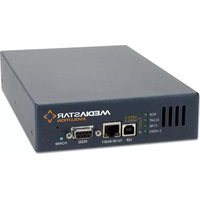
The MediaStar Pro Hub is a 7U rack mountable video hub with either 90/100 (PAL) or 180/200 (NTSC) channel input that will provide TV/AV service to a total of 64 individual endpoints.
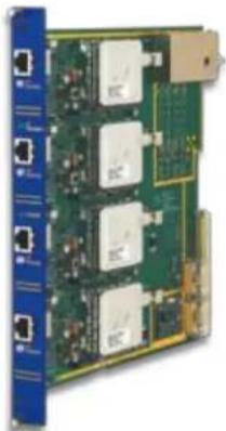
Each Hub can house up to 16 'hot swappable' Quad Outlet Blades (Part 560), each supporting four independent endpoint display devices such as a touch screen panel, PC, or Plasma/LCD display. Quad Cards support either 90/180 (PAL) channels or 100/200 (NTSC) channels with local audio output option available.
Front panel RJ45 sockets allow interconnection with the Receiver Units at distances of up to 800 meters (2,600 ft). An RF Headend (Part KUF series) combines incoming satellite signals and MATV/CATV feeds, with local content from antennas, decoders, cameras, DVDs and VCRs to form an RF backbone for distribution to the Pro Hub. Single or dual RF inputs enable up to 200 NTSC or 180 PAL television channels.
The unit is line powered to support MediaStar Pro Micro TV Settop Receiver Units (Part 507), Micro PC Desktop Receiver Units (Part 508), and Micro Access Receiver Units (Part 512) to enable versatile and scalable TV and AV delivery over Cat-5 cabling infrastructure. Configuration, control and monitoring of the MediaStar
Pro system can be easily accomplished via an IP or RS232/RS485 connection with the MediaStar Controller (Part 700/C) and MediaStar Administration software (Part 461).
What's in the box
- AC Power mains lead
- Cat-5/6 cable
- RS232 cable
- Rack Mounting Kit

natural_image
Front view of a blue network switch device with multiple ports and a green panel on the right side (no visible text or labels)Important Safety Instructions
- Read these instructions.
- Keep these instructions.
- Heed all warnings.
- Follow all instructions.
- Do not use this apparatus near water.
- Clean only with a dry cloth.
- Do not block any ventilation openings. Install in accordance with the manufacturer's instructions.
- Do not install near any heat sources such as radiators, heat registers, stoves or other apparatus (including amplifiers) that produce heat.
-
Do not defeat the safety purpose of the polarised or grounding-type plug. A polarised plug has two blades with one wider than the other. A grounding type plug has two blades and a third grounding prong. The wide blade or the third prong are provided for your safety. If the provided plug does not fit into your outlet, consult an electrician for replacement of the obsolete outlet.
-
Protect the power cord from being walked on or pinched particularly at plugs, convenience receptacles and the point where they exit from the apparatus.
- Only use attachments or accessories specified by manufacturer.
- Use only with the cart, stand tripod, bracket, or table specified by the manufacturer, or sold with the apparatus. When a cart is used, use caution when moving the cart/apparatus combination to avoid injury from tip-over.
- Unplug this apparatus during lightning storms or when unused for long periods of time.
- Refer all servicing to qualified service personnel. Servicing is required when the apparatus has been damaged in any way, such as power-supply cord or plug is damaged, liquid has been spilled or objects have fallen into the apparatus, the apparatus has been exposed to rain or moisture, does not operate normally, or has been dropped.
Quick Start Guide
natural_image
Close-up of a green circuit board with multiple integrated circuits and connectors, mounted on a blue vertical panel (no visible text or symbols)560 Quad Outlet Blades
Each Quad Card allows delivery of baseband video and audio to any device, including Plasmas, LCDs, projectors, touch screen panels, TVs and PC workstations.
Quad Cards support either 90/180 (PAL) channels or 100/200 (NTSC) channels with local audio output option available. A total of four independent endpoint devices can be accommodated from each Card and connect via RJ45 sockets with Receive Units (Part 507) for infra red remote control of each device.
RF Headend
The TV signal input to the Hub must be provided as an RF modulated signal on coax cable terminated with an "F" type connector. The channels delivered to the Hub must be within the range 48MHz to 860MHz at 34 - 36 dBmV for PAL systems or 40 - 42 dBmV for NTSC systems, 75Ω in all cases. The purpose of the RF Headend is to receive broadcast TV channels from disparate sources (e.g. Satellite, "off-air", Digital TV, VCR, etc) and present them in a common modulated format at the correct level and within the required frequency range to the MediaStar Pro Hub. Installation of a Head End requires specialist test equipment and knowledge and is normally undertaken by installers of Satellite and TV services.
RF Amplifier
The RF amplifier takes RF signals from either the RF Headend or directly from a Cable TV company's feed cable (CATV) and is adjusted to provide the input signal levels required by the Hub (34 - 36 dBmV 75W for PAL systems or 40 - 42 dBmV 75W for NTSC systems).
Mediastar Pro System Controller
The System Controller runs the Administration software and holds the system configuration databases. The databases are maintained by the System Administrator software. Remote system maintenance may be enabled by installing the System Administrator on a PC elsewhere on the corporate data network. Note: For remote system administration to function the Controller PC requires a connection to the corporate data network.
Installation
Fit the rack-mountable components into a grounded 19" rack cabinet using cage nuts and bolts. It is recommended that the Hub is secured using 8 bolts, and that it is installed in the rack before any User or External Device cards are installed.
Remove the blanking plates and install the 4-port User card(s) into the Hub. Conventionally, User cards are installed from left to right and External Device cards are installed from right to left. Carefully slide the card into the Hub, ensuring that it is properly located in the guide rails provided. Push home firmly and tighten the knurled fixing screws.
WARNING: Hazardous voltages may be accessible when the cards are removed. Ensure that blanking plates are fitted to all unused slots.
If there is insufficient rack space for all the Hubs and/or PCs it is recommended that the Hubs and TV headend equipment be installed in one rack and the PC's in an adjacent one.
In many installations it will be necessary to reserve rack space for Satellite/Digital TV channel decoder units. Typically, each decoder will require a shelf and 2U of space.
The User Outlets on the Hub are numbered thus: the card slots number from left to right (slot 1 is the furthest left); outlets on a card number from top to bottom. For example, port 22 is the second port down on the sixth card from the left.
Quick Start Guide
RF Amplifier
The RF Amplifier may be mounted on a 2U 19" panel (Part 400-7005), pre-fitted with mounting bolts. It is suggested that the panel is installed at a convenient location at the back of the rack cabinet.
RF Headend
The Hub requires a video feed on coaxial cable terminated in an "F" type connector, bearing TV signal carriers on RF frequencies in the range 48 - 860 MHz. The input power should be between 34 and 36 dBmV (94 - 96 dBmV) for PAL format, or 40-42 dBmV (100 - 102 dBmV) for NTSC format. Signal carriers lower than this level will produce TV pictures that appear "grainy" to the end users.
POWER
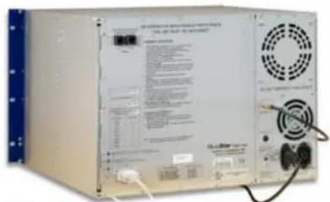
The Power Supply works with 100-240 Volt and 50-60Hz power supplies without adjustments required. Mains lead must be disconnected to remove power from the Hub.
Status Leds
When the Hub is powered on, the upper blue LED (labelled CC) should flash approximately once a second. The lower yellow LED indicates communication with the MediaStar Pro Controller software running on the System Controller (LED on for successful communications, LED off for no communications or an error or fault in communications). The centre red LED will light up the first time the Hub is powered on. Once communications are established with the MediaStar Pro Controller application running on the System Controller, the red LED should extinguish (this may take up to a minute). Thereafter the red LED will light only to indicate a fault in the Hub hardware or corruption of the data held in its NVRAM.
Mediastar Pro Hub Connections
Hub Address
One MediaStar Pro System Controller may control up to 100 Hubs. Each Hub must have a unique identifier, a 4-digit number set using the Hub address switches. The factory default value is 0101. Subsequent Hubs in the chain should be configured with addresses in increments of 1.
If the address switches are adjusted while the Hub is powered on, the change in address will not be registered until the power is cycled (switched off and then on).
507 Micro TV Settop Receiver Unit
natural_image
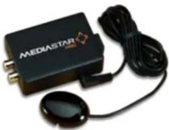
Exterior view of a black MEDIASTAR device with attached cable and earplugs (no text or symbols visible on the device body)The Micro TV Settop Receiver will receive baseband A/V and connect with any television source device such as a plasma screen, LCD, or CRT to enable infra red capability for remote control from any convenient location. The Receiver Unit connects to the front panel RJ45 sockets on the Pro Hub to allow interconnection at distances of up to 800 meters (2,600 ft) using the accompanying IR Sensor (Part 911-4141) and Remote Control Unit (Part 590/1Y).
Included within the scope of delivery: Micro TV Settop Receiver Unit, Mono Audio c/w IR Remote Control, IR Sensor module, connector cables: SCART plug to 2 x phono plugs, Velcro Mounting Kit.
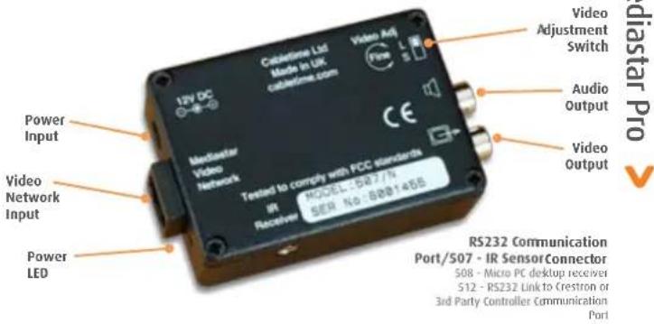
Connect the Micro Settop Receiver to a TV or other display device using the cables provided. The yellow phono socket is the video output and the white phono socket is the audio output. Connect the Micro unit to the MediaStar Pro Hub using an RJ45 patch lead. If the status LED is not flashing, check the connection to the Hub.
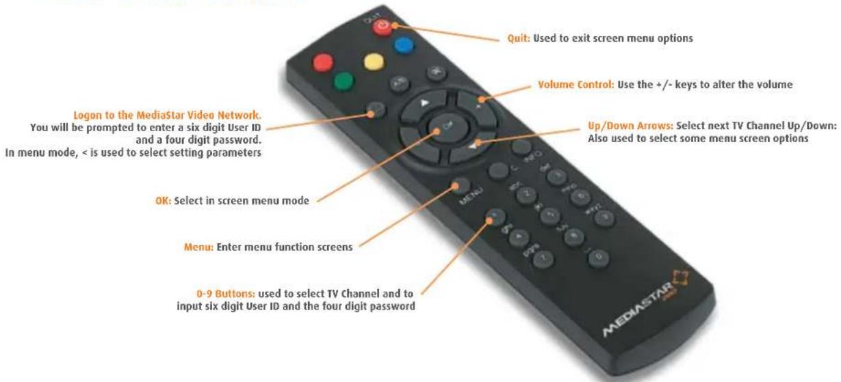
Switch on the TV and select the A/V input channel. Set the Video Adjustment rotary control (fine) and L (long) or S (short) switch to give best picture sharpness. Insert the batteries into the Remote Control Unit. Point the Remote Control at the IR sensor and check that the volume control slider display appears when the volume control buttons are pressed.
If several MediaStar Remote Controls are in use at the same time in the same area, the IR Sensor can be made more directional by fitting the self-adhesive mask. Simply attach the mask such that the hole is directly over the infra-red sensor so as not to block signals.
Quick Start Guide
Mediastar Micro TV Settop Receive Unit Installation Menus:
MediaStar Micro menu screens access user configurable display options and provide system status information.
To configure the display setting options: Press MENU and the following will appear on screen.
View information
▶ Settings
Use the next channel select buttons to select "Settings", then press OK or NEXT/??. The following will appear on screen:
▶ Channel display
Choose how to display the channel name on screen
Channel position
Choose where to display the channel name on screen
Background colour
Choose screen background colour
Update channel
Update the channel list
Use the next channel select buttons to select the required setup option and then press OK or NEXT/??.
Choose which setting parameters you require using the LOGON or LOGOFF buttons and then press OK or NEXT/?? to select or press QUIT to exit screen menu options.
To access system status menus: Press MENU and the following will appear on screen.
▶ View information
Settings
Navigate using the channel select buttons, select 'View Information' and press OK or NEXT/??. The following sub menus will be displayed:
User ID
Shows the id number of the current logged on user.
Micro Settop
Shows micro Settop TV standard, model, software version, address and IR type.
Hub Outlet
Shows connection detail. Hub address, hub outlet and hub software details.
Select QUIT to exit menu mode.
Mediastar Pro Remote Control Unit
Quick Start Guide
508 Micro Pc Desktop Receiver Unit

natural_image
Exterior view of a black MEDIASTAR PRO electronic device with gold pins (no readable text or symbols beyond branding)The Micro PC Desktop Receiver will connect with any desktop PC to receive baseband A/V. The Receiver Unit connects RJ45 sockets on the Pro Hub via the Cat-5/6 infrastructure to allow interconnection at distances of up to 800 meters (2,600 ft). An RS232 connector cable sends signals from the PC to the Receiver.
Included within the scope of delivery: Micro PC Desktop Receiver Unit, Mono Audio c/w 2.5mm Jack Plug to 9-way "D" type RS232 cable, connecting cables: phono to phono; phono to 3.5mm Jack; 3.5mm female to female jack socket adapter, Velcro mounting kit.
Connect the Micro Receiver Unit to the PC using the RS232 cable supplied. Make a note of the communications port used. Next, connect the unit to the PC video card using the yellow phono socket and to the PC sound card inputs using the white phono socket.
Connect the Micro unit to the MediaStar Pro Hub using an RJ45 patch lead. Power on the Micro unit and if the status LED is not flashing, check the connection to the Hub.
Set the Video Adjustment rotary control switch (fine) and L (long) or S (short) switch to give best picture sharpness.
Connectivity For 507/508 And 512 Receiver Units
Installing The Mediastar Pro Desktop Viewing Software
The Desktop Viewing Software requires the following minimum PC specification:
233 MHz processor
32 Mbytes of RAM
10 Mbytes of hard disk space
Windows 95/98 or NT 4
One available Com port capable of 57600 Baud MediaStar Software Version 5 or above
Note: Please consult your Network supervisor before commencing with this installation.
-
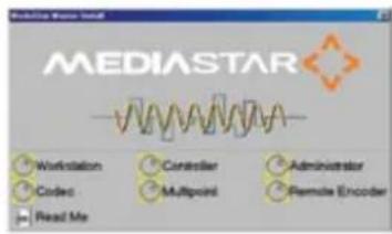
Insert the CD into the PC CD drive. The following screen will appear: ▶
-
Select the following option -
- Follow the remaining installation procedures as instructed on the screen and then restart the PC (please remove the CD before Windows restarts).
The Desktop Viewing Software will now be available using the Windows programs.
Quick Start Guide
512 Micro Access Receiver Unit
Designed for use with Crestron or similar third party touch screen control panels, the Micro Access Receiver will provide a simple RS232 control interface between these devices and the MediaStar Pro Hub so that baseband A/V media can be delivered to a touch screen panel over a Cat-5/6 infrastructure.
Included within the scope of delivery: Micro Access Receiver Unit, Mono Audio, c/w 2.5mm Jack Plug to 9-way "D" type RS232 cable, connecting cables: phono to phono; phono to 3.5mm Jack; 3.5mm female to female jack socket adapter, Velcro mounting kit.
Connectivity
Connect the "Video Out" to the PC Video Card or TV Video Input port. Next, connect the "Audio Out" to the PC Sound Card/TV Audio input port or directly to speakers. Use a Cat-5/6 RJ45 patch lead to connect the Video Network Input to the MediaStar Pro Hub. Connect supplied PSU to Power Input port, and check that the Power LED is lit. Finally, connect the RS232 cable supplied to the Crestron Controller Communications port.
Configuration
Ensure that the Video Network Port used on the MediaStar Pro Hub is configured as a "TV Direct Feed" with the appropriate channels. This is done via MediaStar Pro Administrator software.
The Crestron Controller communications port used should be set for the following:
Bits per second - 9600
Data Bits - 8
Parity - Even
Stop Bits - 1
Flow Control - None
RS232 Cable Connectivity
The power LED located on the MediaStar 512 Micro Access Receiver will flash at one second intervals to indicate a successful communications link with the device. The LED will flash at a faster rate when good serial commands are received.

natural_image
Black rectangular electronic device labeled 'MEDIASTAR PRO' with gold connectors (no additional text or symbols visible)Control Command Interface
The commands used to control the MediaStar 512 Micro Access Receiver consist of a series of ASCII characters. All characters sent to the unit will be echoed back. When a command is successfully accepted the unit will respond with OK. If there is an error, ERR will be shown.
All commands sent to the unit must be preceded with an * (asterisk) character. All command responses generated (except OK and ERR) will be preceded with a # (hash) character.
At power up, and on receipt of a “*?” command, the Micro Access Receiver will show its software version number and the latest set of commands supported.
A short-list of control commands is listed below:
| *Cxxx Select a channel from 001 onwards | |
| *CH | Select the next channel up |
| *CL | Select the next channel down |
| *Vx | Select a volume level between 0-6 (default is 2) |
| *VH | Increase volume level |
| *VL | Decrease volume level |
| *Pxxxx | Used for 4-digit password on restricted channels |
| *Q | Queries current status |
| *? | Displays commands |
Note: As this is a text based command protocol, Windows Hyper Terminal can be used to confirm the operation of the interface.
Quick Start Guide
Technical Specifications
| Video Standards Supported PAL /NTSC | |
| Rear Panel Video Inputs Composite 1V pk-pk (75Ω) | |
| Composite Video SNR (weighted) >71dB | |
| Rear Panel Audio Inputs Stereo 2.2V pk-pk (10KΩ) | |
| RF Input 48-862 MHz Type F (75Ω) | |
| Antenna Mode Input Level 0 to +17dBmV | |
| Video SNR (weighted) 50dB @0 dBmV. 54dB @17 dBmV. | |
| 8 RF TV Carriers Max Input 24dBmV | |
| CAT V Mode Input level 25 dBmV - 40dBmV | |
| Adjacent Carrier Levels Max 2dB Between Adjacent Carriers | |
| Video SNR (weighted) 52dB @25dBmV. 56dB @40dBmV. | |
| IR remote control (*see note) | 38kHz Modulated |
| Hub Communications | Proprietary Protocol |
| Local Control RS232/RS485, 9 pin D type Male | |
| IP Browser Control | 10 Base-T, RJ45 |
Physical Specification
| Dimensions HxWxD | 45x437x350 mm |
| Weight 5Kg/11lb | |
| Mounting 19" Rack | 1U |
| Power Requirement | 3 pin IEC Male 100-264V AC, 1.5A |
| Power Dissipation | 80W max |
| Approvals CE, UL, FCC part 15 class A | |
| Operating Temperature 0-40°C |
\*Additional notes on Infra Red control function
The MediaStar compact Receivers and Hubs provide an IR porting function that enables compact users to send IR control signals from an infra red RCU to remotely located third party equipment. Please note that this function is compatible with third party equipment that utilises the common 38khz modulated IR standards. Other frequencies or proprietary IR codes may not be supported.
Quick Start Guide
> Regulatory Requirement Notices
EUROPE
calnetime Limited declare that the products described in this manual conform to the requirements of the following Directives:
• 89/336/EEC
· 92/31/EEC
• Low Voltage Directive 73/23/EEC
THE STANDARDS APPLIED ARE:
BSEN55022: 1998 Limits and methods of measurement of radio interference characteristics of information technology equipment
BSEN50082-1:1998 Electromagnetic compatibility - generic immunity standard
BSEN60950-1:2000 Specification for safety of information technology equipment, including electrical business equipment
BSEN60065:2002 Audio Video and similar electronic apparatus safety requirements
UNITED STATES OF AMERICA
Cabletime Limited declare this equipment has been tested and found to comply with the limits for a Class A digital device, pursuant to Part 15 of the FCC Rules. These limits are designed to provide reasonable protection against harmful interference when the equipment is operated in a commercial environment. This equipment generates, uses, and can radiate radio frequency energy and, if not installed and used in accordance with the instruction manual, may cause harmful interference to radio communications. Operation of this equipment in a residential area is likely to cause harmful interference in which case the user will be required to correct the interference at his own expense.
• This device complies with part 15 of the FCC Rules.
Operation is subject to the following conditions:
• This device may not cause harmful interference, and
- This device must accept any interference received, including interference that may cause undesired operation.
Whilst all reasonable care has been taken to ensure the accuracy of this publication, the publishers and authors cannot accept responsibility for any errors and omissions. Cabletime Limited reserves the right to revise this publication and to make changes in the content from time to time without notice.
Copyright © Cabletime 2007. All rights reserved. No part of this guide may be reproduced, stored in a retrieval system or transmitted in any form or by any means (electronic, mechanical, photocopying, recording or otherwise) without prior written permission of Cabletime Ltd.

Head Office
Cabletime Ltd, 64 Greenham Road, Newbury, Berkshire, United Kingdom RG14 7HX
T: +44 1635 35111 E: sales@cablelime.com www.cabletime.com
USA Office
Cabletime USA T: 973 288 8010 E: usa@cabletime.com
Asia Office
Cabletime ASIA T: +852 3101 2650 E: asia@cabletime.com
Brought to you by
CABLETIME®


- > Getting Started With MediaStar Pro 500
- What's in the box
- Important Safety Instructions
- Quick Start Guide
- Quad Outlet Blades
- RF Headend
- RF Amplifier
- Mediastar Pro System Controller
- Installation
- WARNING: Hazardous voltages may be accessible when the cards are removed. Ensure that blanking plates are fitted to all unused slots.
- POWER
- Status Leds
- Mediastar Pro Hub Connections
- Hub Address
- Micro TV Settop Receiver Unit
- Mediastar Micro TV Settop Receive Unit Installation Menus:
- View information
- ▶ Settings
- ▶ Channel display
- Channel position
- Background colour
- Update channel
- ▶ View information
- Settings
- User ID
- Micro Settop
- Hub Outlet
- Installing The Mediastar Pro Desktop Viewing Software
- MHz processor
- Mbytes of RAM
- Micro Access Receiver Unit
- Connectivity
- Configuration
- RS232 Cable Connectivity
- Control Command Interface
- \*Additional notes on Infra Red control function
- > Regulatory Requirement Notices
- EUROPE
- THE STANDARDS APPLIED ARE:
- UNITED STATES OF AMERICA
- Head Office
- USA Office
- Asia Office
Brand : Cabletime
Model : 507-PQ
Category : Receiver