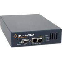
775 MPEG-2/4 - Selector Cabletime - Free user manual and instructions
Find the device manual for free 775 MPEG-2/4 Cabletime in PDF.


| Product Type | MPEG-2/4 Video Encoder / Selector |
| Video Encoding | MPEG-2 MP@ML, MPEG-4 ASP and SP |
| Audio Encoding | MPEG-2 Layer 2, MPEG-4 AAC LC |
| Video Inputs | Composite (BNC), S-Video (Mini DIN), RGB/YPbPr (3x BNC), SCART (RGB + sync on CVBS) |
| Video Formats | PAL and NTSC |
| Audio Inputs | Stereo line level (2x RCA), unbalanced, 10kΩ impedance |
| Network Interface | 10/100 BaseT for streaming and control |
| Serial Port | RS232 for control and configuration |
| USB Interface | USB v1.1 for control and configuration |
| Resolutions (MPEG-2) | FD1, HD1, 2CIF, CIF, QCIF |
| Resolutions (MPEG-4) | FD1, HD1, 2CIF, CIF, QCIF; Dual Encode (CIF + FD1) |
| Bitrate Control | Constant, Variable (MPEG-2); Constant, Variable, Average (MPEG-4) |
| Stream Modes | Unicast or Multicast |
| Power Supply | 100-240 VAC, 15 W via IEC connector |
| Dimensions (W x D x H) | 14.3 cm x 22 cm x 4.1 cm (5.7" x 8.7" x 1.7") |
| Weight | 1.1 kg (2.4 lbs) |
| Operating Temperature | 0°C to 40°C (32°F to 104°F) |
| Compliance | FCC Part 15 Class A, CE, CB |
| Configuration Interface | Web browser, RS232, USB, Telnet |
| Default IP Address | 191.53.51.208 (static, configurable) |
| Safety | Class I equipment with protective earth |
| Included Accessories | AC mains cable, RS232 cable, RJ45 patch cable, BNC-to-phono adaptor, USB cable & driver CD, adhesive feet, labels |
Frequently Asked Questions - 775 MPEG-2/4 Cabletime
User questions about 775 MPEG-2/4 Cabletime
0 question about this device. Answer the ones you know or ask your own.
Ask a new question about this device
Download the instructions for your Selector in PDF format for free! Find your manual 775 MPEG-2/4 - Cabletime and take your electronic device back in hand. On this page are published all the documents necessary for the use of your device. 775 MPEG-2/4 by Cabletime.
USER MANUAL 775 MPEG-2/4 Cabletime
The MediaStar Evolution 775 Encoder converts analogue video and audio signals to MPEG-2 or MPEG-4 digital signals so that they can be streamed over a LAN/WAN data network.
Separate hardware or software viewing applications connected to the same LAN or WAN can decode data streams from the network and present video and audio for viewing at multiple remote locations.
What's in the box
- 775 Encoder unit
- AC mains power cable
• RS232 serial comms cable - RJ45 patch cable
• BNC to phono adaptor
• USB comms cable and driver CD
• Self adhesive desktop feet kit
• Video source/IP address label

Important Safety Instructions
- Read these instructions.
- Keep these instructions.
- Heed all warnings.
- Follow all instructions.
- Do not use this apparatus near water.
- Clean only with a dry cloth.
- Do not block any ventilation openings. Install in accordance with the manufacturer's instructions.
- Do not install near any heat sources such as radiators, heat registers, stoves or other apparatus (including amplifiers) that produce heat.
-
Do not defeat the safety purpose of the polarised or grounding-type plug. A polarised plug has two blades with one wider than the other. A grounding type plug has two blades and a third grounding prong. The wide blade or the third prong are provided for your safety. If the provided plug does not fit into your outlet, consult an electrician for replacement of the obsolete outlet.
-
Protect the power cord from being walked on or pinched particularly at plugs, convenience receptacles and the point where they exit from the apparatus.
-
Only use attachments or accessories specified by manufacturer.
-
Use only with the cart, stand tripod, bracket, or table specified by the manufacturer, or sold with the apparatus. When a cart is used, use caution when moving the cart/apparatus combination to avoid injury from tip-over.
-
Unplug this apparatus during lightning storms or when unused for long periods of time.
-
Refer all servicing to qualified service personnel. Servicing is required when the apparatus has been damaged in any way, such as power-supply cord or plug is damaged, liquid has been spilled or objects have fallen into the apparatus, the apparatus has been exposed to rain or moisture, does not operate normally, or has been dropped.

Quick Start Guide
Installation
WARNING: There are no user serviceable parts within the MediaStar Evolution Encoder. This unit contains hazardous (mains) voltages and should only be opened by suitably qualified service personnel.
When locating the Encoder unit, ensure that a clearance distance of 25mm (1") is maintained at the front and rear of the unit to allow free ventilation airflow. Items that could accidentally block the ventilation grills or impede the cooling airflow must not be located near the unit. The Encoder must not be installed where there is a possibility of exposure to condensation, dripping or splashing liquids, and containers filled with fluid should not be located in the vicinity of the unit.
Using the AC mains power cable supplied, plug in the Encoder. This device must be installed using a mains (AC supply) plug and socket that contains a protective earth (ground) connection. The mains socket must be located near the equipment, remain operable and be easily accessible to disconnect the unit in the case of an emergency.
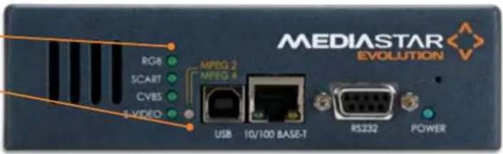
Ensure that the blue Power LED is lit, showing that power is on. All the LEDs on the front will turn on and then off after approximately 30 seconds but the blue Power LED will stay lit, along with the video input indicator and the MPEG stream status LEDs.
The video input indicator LED shows what type of video input is selected: RGB/YPbPr, SCART (RGB with sync on Composite), CVBS (Composite), or S-VIDEO. The selected LED will flash if there is no input signal detected.
The MPEG stream status LED shows what type of encoding standard is selected. Solid orange indicates MPEG-2 and solid green indicates MPEG-4. This LED will flash (orange or green depending on which is selected) if the network data streams have been disabled. It will flash red during a software upgrade, and will become solid red if the Encoder requires service support.
The Encoder's configuration is set using web pages served by the Encoder unit. A network connection is required to view these and a suitable IP address will need to be assigned.
Selected Video Input Indicator
MPEG Stream status LED
MPEG-2 Enabled = Orange LED
MPEG-4 Enabled = Green LED
MPEG Stream Disabled = LED Flashes
Service Required = Solid Red
Software Upgrade=Flashing Red
Connecting Video And Audio Inputs
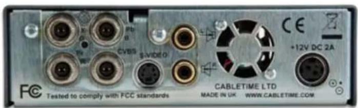
Only one type of video input source can be selected at a time, either RGB/YPbPr, SCART (RGB with sync on Composite), CVBS (Composite) or S-Video. When YPbPr is selected, the RGB LED will be lit. Stereo audio inputs are unbalanced with 10k ohm impedance.
Y/G Pb/B
Pr/R CVBS
Quick Start Guide
Selecting IP Address
A suitable IP address for the Encoder should be selected before it is connected to a network. The Evolution 775 Encoder is pre-configured with a static IP address of 191.53.51.208, however if this is not suitable for use on your network the Encoder must be reconfigured.
Reconfiguring the Encoder IP address can be achieved using the RS232, USB, or Telnet Command interface, or via a browser application such as Internet Explorer connected locally to a PC with a Cat-5 network crossover cable.
Configuring With A Browser Application
Using a browser such as Internet Explorer, type the IP address (http://191.53.51.208) into the browser window and the Evolution Encoder Admin window will open. This allows entry and adjustment of all Encoder operational parameters such as network setup, video input, encoding stream, and password protection.
Configuring With RS232 Serial Or USB Communications
Plug the supplied cable into the Encoder's RS232 interface and connect with a laptop/PC. If this is not available a USB interface may be used. A CD supplied with the 770 rack contains the appropriate USB driver software to install a USB 'com' port onto a Microsoft Windows 2000 or XP platform when there is no RS232 serial port available on the laptop/PC.
Use a terminal emulator program (e.g. HyperTerminal) to issue commands. The serial communications settings are: 115200 Baud, 8 bits data, 1 stop bit, no parity, no flow control.
To set the static IP address, use the command:
Setipconf, mpeg_encoder="Encoder1", localaddr=192.168.66.10, localnetmask=255.255.255.0, gatewayaddr=0.0.0.0, dnsaddr=0.0.0.0, dscp=0
In the command response you will see that status = "0" and statusstring = "Success"
Connecting To The Network
Only when you are satisfied that the IP address of the Encoder is suitable, plug the Encoder into the LAN using the RJ45 patch cable supplied. The RJ45 LEDs will illuminate to indicate a network connection.
Important : Ensure That The Encoder Is Connected To A Network Port Configured With 'Auto-Negotiation' On.
Evolution Encoder Admin
These HTML configuration menus allow you to enter and adjust all Encoder operational parameters. Full contextual HELP is provided on the right side of the screen. When alterations and changes have been made, press the APPLY button at the bottom of the page to make these take effect. The Encoder configuration menus include:
Status
Shows the current status of the Encoder, including: encoder network name, serial number, encoding standard, video source present status, stream details, IP address, video input selected, software/hardware versions, and enablement codes entered.

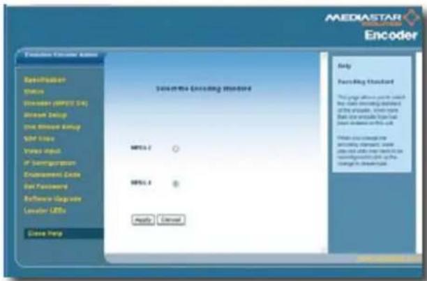
Encoder
Allows selection of the video encoding standard, either MPEG-2 or MPEG-4. MPEG-4 provides a similar picture quality as MPEG-2 but at a lower network bandwidth.
Quick Start Guide
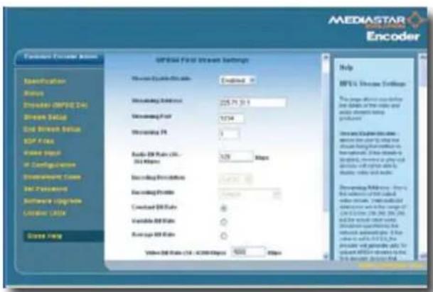
Stream Setup
Defines the details of the video and audio streams being produced.
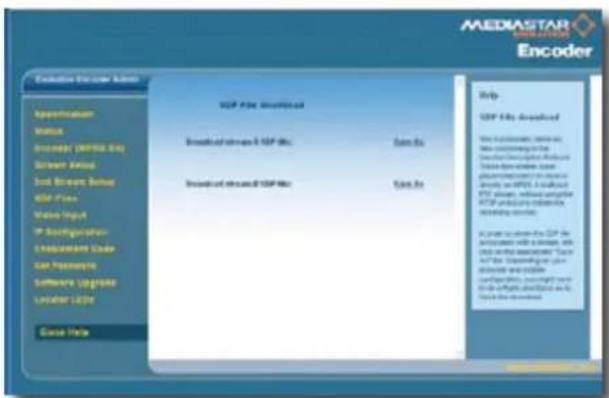
SDP Files
This functionality retrieves files conforming to the Session Description Protocol (SDP). These files are used by some players/decoders to select an MPEG-4 stream.
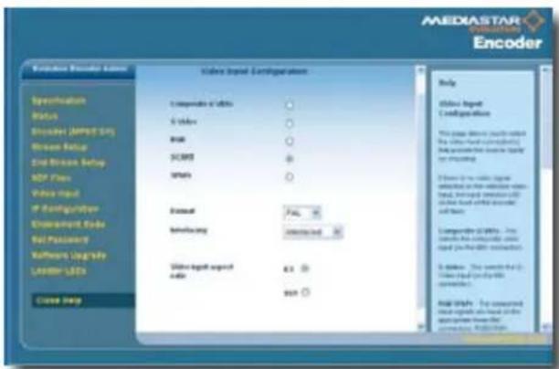
Video Input
Select the video input connector(s) and video format for the source signal to be encoded: CVBS (Composite), S-Video, RGB, SCART (RGB with sync on Composite), YPbPr (Component).
Select the video format: PAL or NTSC Set interlacing: Progressive or Interlaced Set the video aspect ratio: 4:3 or 16:9
IP Configuration
Network configuration of the Encoder is set up here. These settings should be confirmed with your network administrator before installing this unit on the network.
Note that if the DHCP setting is used, following an Encoder reset, the unit may be given an IP address that is different from the one previously used.

Quick Start Guide
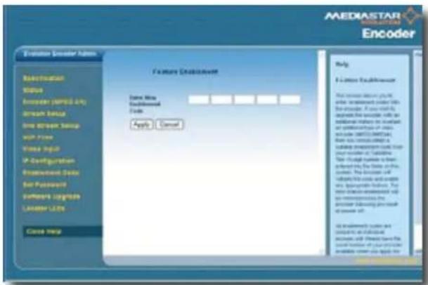
Enablement Code
To upgrade the Encoder with an additional feature (e.g. additional type of video encoder: MPEG-2/MPEG-4) a suitable enablement code must be obtained from your reseller or Cabletime. This 15-digit number is entered into the fields on this screen. The Encoder will validate the code and enable any appropriate feature. Note that all enablement codes are unique to an individual unit.
Set Password
A password will prohibit unauthorised access to all the Encoder configuration web pages, and will also prohibit changes being made through the RS232, USB or Telnet command interfaces (unless the password is specified in each command). Valid passwords consist of six numbers 0-9.

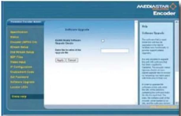
Software Upgrade
Encoder software may be upgraded to facilitate new functionality or provide support related upgrades. This screen enables hourly upgrade checks and specifies the HTP file server location that the Encoder will check for upgrades.
Locator Leds
The locator LED functionality causes the LEDs on the front of an Encoder to flash in a 'ripling' sequence. This allows for identification of a specific Encoder in a multi-Encoder rack system. The location LED flash duration is: /Off /5 secs/ 2 mins/ 20 mins.

Quick Start Guide
Technical Specifications
Video encoding MPEG-2 MP@ML. FD1, HD1, 2CIF, CIF, and QCIF resolutions
Unicast or multicast transport streams
Constant and variable bitrate encoding
MPEG-4 ASP and SP. FD1, HD1, 2CIF, CIF and QCIF resolutions
Unicast or multicast ISMA streams
Constant, variable and average bitrate encoding
MPEG-4 Dual Encode: Two simultaneous MPEG-4 encodes of the
same source; one low bitrate (CIF resolution) and one high bitrate
(FD1 resolution)
Audio encoding MPEG-2 Layer 2
MPEG-4 AAC LC
Video inputs Composite - BNC
S-Video - Mini DIN
RGB/YPbPr - 3 x BNC
SCART (RGB + sync on CVBS)
PAL and NTSC
Audio inputs Stereo line level - 2 x RCA
Network 10/100 BaseT for streaming and control interface
Serial Port RS232 interface for control and configuration
USB USB v1.1 interface for control and configuration
Power 100 - 240VAC . 15 Watts via IEC Mains connector
Dimensions 14.3cm x 22cm x 4.1cm, 5.7" x 8.7" x 1.7"
Weight 1.1Kg
Environmental 0 - 40°C
Approvals FC Part 15, CE, CB
Quick Start Guide
> Regulatory Requirement Notices
EUROPE
calnetime Limited declare that the products described in this manual conform to the requirements of the following Directives:
• 89/336/EEC amended by 92/31/EEC
• 73/23/EEC amended by 93/68/EEC Low Voltage Directive
THE STANDARDS APPLIED ARE:
EN55022:1998 Limits and methods of measurement of radio interference characteristics of information technology equipment
EN61000-6-1:2001 Electromagnetic compatibility – generic immunity standard
IEC60950-1:2001 Specification for safety of information technology equipment, including electrical business equipment
EN60950-1:2001
UNITED STATES OF AMERICA
Cabletime Limited declare this equipment has been tested and found to comply with the limits for a Class A digital device, pursuant to Part 15 of the FCC Rules. These limits are designed to provide reasonable protection against harmful interference when the equipment is operated in a commercial environment. This equipment generates, uses, and can radiate radio frequency energy and, if not installed and used in accordance with the instruction manual, may cause harmful interference to radio communications. Operation of this equipment in a residential area is likely to cause harmful interference in which case the user will be required to correct the interference at his own expense.
• This device complies with part 15 of the FCC Rules.
Operation is subject to the following conditions:
• This device may not cause harmful interference, and
- This device must accept any interference received, including interference that may cause undesired operation.
Correct Disposal Of This Product
This marking shown on the product or its literature, indicates that it should not be disposed with other household wastes at the end of its working life. To prevent possible harm to the environment or human health from uncontrolled waste disposal, please separate this from other types of wastes and recycle it responsibly to promote the sustainable reuse of material resources.

Whilst all reasonable care has been taken to ensure the accuracy of this publication, the publishers and authors cannot accept responsibility for any errors and omissions. Cabletime Limited reserves the right to revise this publication and to make changes in the content from time to time without notice.
Copyright © Cabletime 2007. All rights reserved. No part of this guide may be reproduced, stored in a retrieval system or transmitted in any form or by any means (electronic, mechanical, photocopying, recording or otherwise) without prior written permission of Cabletime Ltd.

Head Office
Cabletime Ltd, 64 Greenham Road, Newbury, Berkshire, United Kingdom RG14 7HX
T: +44 1635 35111 E: sales@cabletime.com www.cabletime.com
USA Office
Cabletime USA T: 973 288 8010 E: usa@cabletime.com
Asia Office
Cabletime ASIA T: +852 3101 2650 E: asia@cabletime.com
Brought to you by
CABLETIME®


- What's in the box
- Important Safety Instructions
- Quick Start Guide
- Installation
- Selected Video Input Indicator
- MPEG Stream status LED
- Connecting Video And Audio Inputs
- Selecting IP Address
- Configuring With A Browser Application
- Configuring With RS232 Serial Or USB Communications
- Connecting To The Network
- Evolution Encoder Admin
- Status
- Encoder
- Stream Setup
- SDP Files
- Video Input
- IP Configuration
- Enablement Code
- Set Password
- Software Upgrade
- Locator Leds
- Technical Specifications
- > Regulatory Requirement Notices
- EUROPE
- THE STANDARDS APPLIED ARE:
- UNITED STATES OF AMERICA
- Correct Disposal Of This Product
- Head Office
- USA Office
- Asia Office
Brand : Cabletime
Model : 775 MPEG-2/4
Category : Selector