
778-S-SD - Server Cabletime - Free user manual and instructions
Find the device manual for free 778-S-SD Cabletime in PDF.


| Product Type | Server |
| Brand | Cabletime |
| Model | 778-S-SD |
| Form Factor | 1U Rackmount |
| Dimensions (W x D x H) | 17.7 x 19.0 x 1.75 inches (approx.) |
| Weight | 15 lbs (approx.) |
| Power Supply | AC 100-240V, 50-60Hz, 250W |
| Processor | Intel Xeon or equivalent |
| Memory | 16GB DDR4 (expandable) |
| Storage | 2 x 1TB SATA HDD (RAID capable) |
| Network Interfaces | 2 x Gigabit Ethernet ports |
| Operating System | Linux/Windows Server compatible |
| Cooling | Dual hot-swappable fans |
| Main Functions | File sharing, data storage, application hosting, network management |
| Maintenance | Keep in a dust-free environment; clean air filters quarterly |
| Safety Precautions | Disconnect power before opening chassis; use anti-static strap |
| Spare Parts & Repairability | Contact Cabletime support for authorized replacement parts |
| Warranty | 3 years limited hardware warranty |
| Compliance | FCC, CE, RoHS |
| Standards | IEEE 802.3, IPMI 2.0 |
Frequently Asked Questions - 778-S-SD Cabletime
User questions about 778-S-SD Cabletime
0 question about this device. Answer the ones you know or ask your own.
Ask a new question about this device
Download the instructions for your Server in PDF format for free! Find your manual 778-S-SD - Cabletime and take your electronic device back in hand. On this page are published all the documents necessary for the use of your device. 778-S-SD by Cabletime.
USER MANUAL 778-S-SD Cabletime
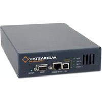
> Getting started with the MediaStar 778 Multi Format Input SD-HD Encoder
Models: 778-S-SD, 778-S-HD, 778-D-SD, 778-D-HD
The MediaStar Evolution 778 Encoder is a MPEG2 or MPEG4-10/H264 video and audio encoder that is housed in a MediaStar 770 3RU 19" rack. It can take the video input from a variety of different source formats (Composite, S-Video, YPbPr, RGB, VGA or HDMI) and will scale the images to either SD or HD resolutions. The video and accompanying audio is then encoded into MPEG2 or H264 data, and is then streamed onto a LAN. Separate decoder units or PC software clients can then display the video and audio at any network enabled location.
The unit has a front panel mounted LCD and push buttons to allow easy network setup and source selection, with an embedded http web page server providing configuration web pages for more advanced features.
The 778 unit may be purchased with a single or dual set of video inputs (778-S-xx and 778-D-xx units), and also with either an SD output stream resolution, or a selectable SD/HD output stream resolution (778-x-SD or 778-x-HD).
What's in the box
- 778 Encoder blade
- 2m CAT-5 patch lead
- 1.5m HDMI cable
• 1.5m YPbPr component video cable
• 2m SVGA cable (15 way HDD plugs) - 1m 3.5mm Jack to 2 x Phono (audio) cable
• IR Blaster assembly (Part 911-4153)

Please note: 778-D-xx units have two sets of video/audio input cables included.
Important Safety Instructions
- Read these instructions.
- Keep these instructions.
- Heed all warnings.
- Follow all instructions.
- Do not use this apparatus near water.
-
Clean only with a dry cloth.
-
Do not block any ventilation openings. Install in accordance with the manufacturer's instructions.
-
Do not install near any heat sources such as radiators, heat registers, stoves or other apparatus (including amplifiers) that produce heat.
-
This unit must be installed using a mains (AC supply) plug and socket that contains a protective earth (ground) connection. The mains socket must be located near the equipment, remain operable and be easily accessible to disconnect the unit in the case of an emergency.
-
Do not defeat the safety purpose of the polarised or grounding-type plug. A polarised plug has two blades with one wider than the other. A grounding type plug has two blades and a third grounding prong. The wide blade or the third prong are provided for your safety.
If the provided plug does not fit into your outlet, consult an electrician for replacement of the obsolete outlet.
- Protect the power cord from being walked on or pinched particularly at plugs, convenience receptacles, and the point where they exit from the apparatus.
-
Only use attachments/accessories specified by the manufacturer.
-
Use only with the cart, stand tripod, bracket, or table specified by the manufacturer, or sold with the apparatus. When a cart is used, use caution when moving the cart/apparatus combination to avoid injury from tip-over.
-
Unplug this apparatus during lightning storms or when unused for long periods of time.
-
Refer all servicing to qualified service personnel. Servicing is required when the apparatus has been damaged in any way, such as power-supply cord or plug is damaged, liquid has been spilled or objects have fallen into the apparatus, the apparatus has been exposed to rain or moisture, does not operate normally, or has been dropped.
Warning: There are no user serviceable parts within the Mediastar 770 Rack or 778 Encoder unit.

Quick Start Guide
Installation
The 778 Encoder must be installed in a MediaStar 770 rack. The Encoder can be installed in the rack with the rack power on or off. If the rack is powered, take care to ensure this module is engaged correctly in the plastic card guides and does not touch adjacent cards as it is slid into (or pulled out of) the rack. If the 770 rack is powered down to install a new module, please remember that all video/audio services being provided by the rack will be lost while it is powered off.
To install a 778 Encoder, do the following:
-
Remove the existing front panel blanking plate(s) on the rack. This is done by unscrewing the fingerscrew fasteners. Retain this blanking plate in case the Encoder module is removed from the rack in the future.
-
Carefully locate the top and bottom edges of the Encoder's printed circuit board (PCB) into the plastic rack slides, and gently push it in. As the 'blade' reaches the back of the rack, the plastic aperture cover on the rear of the rack will be pushed off (2 in the case of 778-D-xx units). Collect and dispose of correctly. If the rack is powered up, the Encoder will automatically power up as it is pushed in, and the BLUE power LED on the front of the encoder will be on. The LCD panel will show the boot up progress of the unit. Until the unit is fully booted, only selected setup items are available to view on the LCD.
-
Tighten the top and bottom finger screw fasteners to hold the Encoder in the rack.
-
Connect the appropriate network and control interface cables on the front side of the Encoder.
-
The video and audio input connectors are located on the rear of the Encoder and now protrude through the rear of the 770 rack. Connect the Encoder unit to the source device using the appropriate video and audio interface cables. A Composite video source should be input into the GREEN phono connector on the rear of the unit, and S-Video should be input into the GREEN (Y) and BLUE (C) phono connectors (with a suitable adapter). If HDMI audio is not being used, connect the analogue audio source to the 3.5mm jack socket audio input using the phono adapter cable supplied.
Booting Up
During boot-up, the status LED on the front of the encoder will flash orange. The LCD will show the boot-up progress. When booting is complete the status indicator LED will change colour to GREEN or flashing GREEN to indicate whether the selected video input source signal is present or not. The LCD will then reflect the operational status of the encoder.
After boot-up, if the status LED changes to a constant RED colour, an internal error has occurred in the encoder, and it should be returned to Cabletime or your reseller for service. If the status LED is flashing RED, then a software upgrade is in progress, and it is important that the Encoder remains powered with a valid network connection until the unit reboots and resumes normal operation.
Quick Start Guide
Front Panel Operation
The front panel LCD can be used with the three adjacent push buttons to view status information and configure the operation of the unit. The UP and DOWN buttons scroll up and down menus and change parameter values. The OK button selects the currently displayed menu item or confirms a parameter change. Pressing the UP and DOWN buttons and releasing them together returns up a menu level, usually aborting a parameter change.
The upper line of the LCD display shows the setting name, and the lower line shows the parameter itself and any instructions on how to change the current setting.
Pressing the UP, DOWN and OK buttons for 5 seconds and releasing them together will present a unit RESET option. Pressing the OK button to confirm will then reboot the encoder.
The structure of the menus presented on the LCD are as follows:
Part Number and Status
Stream 1 Information
Stream 2 Information (778-D-xx units only)
Video Input selection
Input set selection (778-D-xx units only)
Composite
S-Video
YPbPr
RGB
VGA
HDMI
Picture Adjustments
Input set selection (778-D-xx units only)
Move Up/Down
Move Left/Right
Scale Vertical
Scale Horizontal
Picture brightness
Picture contrast
IP address settings
DHCP (activate/show allocated address)
Static IP address (activate/show static IP address)
View/Edit IP address
View/Edit Netmask
View/Edit Gateway address
View/Edit DNS address
Network Link
Unit details
MAC address
Serial number
Software version number
Help
Various help topics
Setting the Encoder's IP address
Each Encoder is pre-configured with its IP address set to DHCP. When connected to the network the Encoder will automatically obtain an IP address from the DHCP server. The IP address being used can be seen on the front panel LCD, under the IP address settings/DHCP menu.
If necessary, the MAC address of the unit can be found under the Unit Details/MAC Address menu, or on the label on the bottom face of the unit.
If a static IP address needs to be set, use the front panel LCD and push buttons to set the correct address. Static IP address selection will need to be activated first, and then enter the IP address and netmask etc on the appropriate menus.
Once IP connectivity is established with the unit, use standard browser software (MS Windows Internet Explorer, Firefox, Google Chrome or Safari for example) to access the detailed configuration menus. Enter the IP address of the 778 unit into the URL address bar, to see the menus.
Contact your network administrator to ensure any manual IP address settings made are appropriate for your network.
Quick Start Guide
Configuration Menus
The Encoder's web page configuration menus allow the full range of operational parameters to be set. When using the web pages, full contextual help is provided on the right side of the screen. When changes have been made, press the APPLY button at the bottom of the page to ensure these take effect.
Configuration menus include:
Status - shows the current status of the Encoder, including the Part number, Mac Address, IP Address, Netmask, Gateway, DNS, Software Version, Serial Number, Temperature, Encoder name, Encoding standard, video source(s), video/audio stream address, video/audio stream bandwidth and RS232 status. Please note, the temperature shows the internal unit temperature and not the ambient temperature. Readings up to 70°C are normal.
Encoding Standard – facilitates the selection of the video and audio encoding standards, the bit rate control strategy and the actual video and audio bit rate.
Input - sets the video and audio input being used, and the stream IP address being transmitted by the encoder. Also sets the stream TTL and DSCP controls.
IP Configuration - allows specification of the Network Connection; Static or DHCP addressing, Hostname, IP Address, Subnet Mask, and Default Gateway settings. Confirm these with the network administrator before configuring.
Picture Adjustment - allows the following parameters of the input picture to be adjusted: Horizontal position, vertical position, horizontal scale, vertical scale, picture brightness and picture contrast. On dual input Encoders two control sets are presented.
RS232 Port – this is used to configure the RS232 port for SIPI command mode or as an IP – RS232 bi-directional pass through adaptor.
Event Log - displays a list of events generated by the unit.
Email Logs - configuration of who log files are emailed to and when.
SNMP - allows configuration of SNMP community and trap targets.
Enablement Code - enter enablement codes here to reconfigure or expand the capabilities of your unit. Details can be obtained from your reseller or Cabletime.
Set Endpoint Password - A password may be set to prevent the unauthorised modification of the Encoder configuration. A password must consist of exactly six digits from 0-9. If the password gets lost, contact Cabletime for assistance.
Software Upgrade - specify the http server that the Encoder will look at for software updates.
Locator LED - allows the status LED to be flashed ORANGE/GREEN to identify the physical encoder unit.
IR Blaster 1/2 - this allows you to select the IR remote control to emulate, and press IR buttons on it.
Quick Start Guide
Product Specification
Feature 778-x-yy support
| Physical 778-S-xx H129 x W41 x D220mm, 1 x 770 rack slot (1 of 9) 500g |
| 778-D-xx H129 x W83 x D220mm, 2 x 770 rack slot (2 of 9) 700g |
| Ambient operating temperature range 0° - 40° Centigrade 770 rack ambient |
| Power Supply 12W (from 770 rack) |
| LAN 10/100/1000 Base-T, Auto MDIX |
| Video input sets 778-S-xx 1 set |
| 778-D-xx 2 sets |
| Video Inputs supported (on each input set) Composite, S-Video - NTSC, PAL |
| YPbPr, RGB (SOG) - 480i, 576i, 480p, 576p 720p50, 720p60, 1080i50, 1080i60, , 1080p50, 1080p60 |
| VGA - 640x480@60, 800x600@60, 1024x768@60, 1280x720@60, 1280x800@60, 1280x1024@60, 1366x768@60, 1440x900@60, 1600x1200@60, 1680x1050@60, 1920x1080@60, |
| 1920x1200@60(RB) |
| HDMI 1.3 - VGA resolutions listed plus YPbPr, RGB (SOG) resolutions listed |
| HDMI Stereo | Single channel stereo digital audio |
| Analogue Audio Stereo (2.2V pk-pk into a 10K Ohm load) |
| Video Encoding MPEG2 MP@HL CBR/VBR encoding (1.5 - 15 Mbps) |
| MPEG4-10/H264 MP@L4 CBR/VBR encoding (1.5 - 12 Mbps) |
| Audio Encoding MPEG1-Layer 2 - 32, 44.1, 48 KHz sampling, 64 - 384 Kbps Stereo AAC/LC encoding - 16, 32, 44.1, 48, 88.2, 96 KHz sampling, 40 - 576 Kbps Stereo |
| Encoded Stream Formats | Multicast/Unicast UDP MPEG2-TS |
| Multicast/RTP video and audio streams (for use with Quicktime via on-board RTSP server) |
| Video resolutions: 480i, 576i, 720p50, 720p60, 1080i50, 1080i60, 1080p25, 1080p30 |
| USB Host | 1 x USB 2.0 High Speed Host(Used for software upgrades with a USB memory stick) |
| USB Comms | USB Serial Comms device for external configuration/control |
| Infra-Red Blasterspage or IP command remote activation | 2 off outputs supporting Sky, Sky+, SkyHD IR formats with web |
| RS232 Port(s) Rx, Tx, CTS, RTS up to 115200 Baud Configured for SIPI external configuration/control or IP to RS232 bi-directional pass through for external device control (2 x RS232 ports on 778-D-xx units) |
Quick Start Guide
Product Specification
Feature 778-x-yy support
| Temperature Monitoring Operating temperature available remotely via web interface or on-screen menu |
| External IP control interface ASCII Command/configuration via IP interface, USB comms and RS232 comms interfaces |
| SNMP traps Defined ‘Events’ sent to third party SNMP manager (MIB available on request) |
| Field Software Upgrade From remote HTTP server or from USB memory stick inserted in front panel USB host connector |
| Automatic email of Event logs Via external SMTP server |
Correct Disposal of this product
This marking shown on the product or its literature, indicates that it should not be disposed with other household wastes at the end of its working life. To prevent possible harm to the environment or human health from uncontrolled waste disposal, please separate this from other types of wastes and recycle it responsibly to promote the sustainable reuse of material resources.

natural_image
Simple line drawing of a trash bin with crossed lines indicating no waste or restriction (no text or symbols)Quick Start Guide
> Regulatory Requirement Notices
EUROPE
calnetime Limited declare that the products described in this manual conform to the requirements of the following Directives:
• 2004/108/EC EMC Directive
• 2006/95/EC Low Voltage Directive
THE STANDARDS APPLIED ARE:
EN55022:2006 Information technology equipment. Radio disturbance characteristics
EN61000-3-2:2006 Electromagnetic compatibility (EMC). Limits for harmonic current emissions
EN61000-3-3:2008 Electromagnetic compatibility (EMC). Limits. Limitations of voltage changes, voltage fluctuations and flicker
EN61000-6-1:2001 Electromagnetic compatibility (EMC) Part 6-1 Immunity
EN60950-1:2006 + A11:2009 Information technology equipment. Safety General requirements
IEC60950-1:2005 Specification for safety of information technology equipment, including electrical business equipment, with CB variations for US, Canada, Japan, and Australia
UNITED STATES OF AMERICA
Cabletime Limited declare this equipment has been tested and found to comply with the limits for a Class A digital device, pursuant to Part 15 of the FCC Rules Subpart B (15.107, 15.109). These limits are designed to provide reasonable protection against harmful interference when the equipment is operated in a commercial environment. This equipment generates, uses, and can radiate radio frequency energy and, if not installed and used in accordance with the instruction manual, may cause harmful interference to radio communications. Operation of this equipment in a residential area is likely to cause harmful interference in which case the user will be required to correct the interference at his own expense.
• This device complies with part 15 of the FCC Rules.
Operation is subject to the following conditions:
• This device may not cause harmful interference, and
- This device must accept any interference received, including interference that may cause undesired operation.
Whilst all reasonable care has been taken to ensure the accuracy of this publication, the publishers and authors cannot accept responsibility for any errors and omissions. Cabletime Limited reserves the right to revise this publication and to make changes in the content from time to time without notice.
Copyright © Cabletime 2010. All rights reserved. No part of this guide may be reproduced, stored in a retrieval system or transmitted in any form or by any means (electronic, mechanical, photocopying, recording or otherwise) without prior written permission of Cabletime Ltd.

Head Office
Cabletime Ltd, 64 Greenham Road, Newbury, Berkshire, United Kingdom RG14 7HX
T: +44 1635 35111 E: sales@cablelime.com www.cabletime.com
USA Office
Cablelime USA T: 973 770 8071 E: usa@cablelime.com
Asia Office
Cabletime ASIA T: +852 3101 2650 E: asia@cabletime.com


- > Getting started with the MediaStar 778 Multi Format Input SD-HD Encoder
- What's in the box
- Important Safety Instructions
- Quick Start Guide
- Installation
- Booting Up
- Front Panel Operation
- Setting the Encoder's IP address
- Configuration Menus
- Product Specification
- Correct Disposal of this product
- > Regulatory Requirement Notices
- EUROPE
- THE STANDARDS APPLIED ARE:
- UNITED STATES OF AMERICA
- Head Office
- USA Office
- Asia Office
Brand : Cabletime
Model : 778-S-SD
Category : Server