AVS-HDB-TX - AV Extender Black Box - Free user manual and instructions
Find the device manual for free AVS-HDB-TX Black Box in PDF.


| Product Type | AV Extender (HDBaseT Transmitter) |
| Model | AVS-HDB-TX |
| Brand | Black Box |
| Dimensions (W x D x H) | 100 x 60 x 20 mm |
| Weight | 200 g |
| Power Supply | 5V DC, 1A |
| Video Input | 1x HDMI Type A (female) |
| Video Output | 1x RJ45 (HDBaseT) |
| Max Resolution | 4K@60Hz (4:4:4) |
| HDCP Support | HDCP 2.2 |
| Transmission Distance | Up to 100 m (Cat6) |
| Audio Support | Up to 7.1ch PCM, Dolby TrueHD, DTS-HD MA |
| EDID Management | Built-in EDID emulation |
| IR Pass-through | Yes, via 3.5mm jack |
| RS-232 Pass-through | Yes, via 3.5mm jack |
| LED Indicators | Power, Link, Signal |
| Housing Material | Metal |
| Operating Temperature | 0°C to 50°C |
| Storage Temperature | -20°C to 70°C |
| Compliance | CE, FCC, RoHS |
| Package Contents | AVS-HDB-TX unit, power adapter, IR emitter cable, RS-232 adapter, user manual |
Frequently Asked Questions - AVS-HDB-TX Black Box
User questions about AVS-HDB-TX Black Box
0 question about this device. Answer the ones you know or ask your own.
Ask a new question about this device
Download the instructions for your AV Extender in PDF format for free! Find your manual AVS-HDB-TX - Black Box and take your electronic device back in hand. On this page are published all the documents necessary for the use of your device. AVS-HDB-TX by Black Box.
USER MANUAL AVS-HDB-TX Black Box
Video Extender - 4K HDMI, IR, RS-232 Transmitter and Receiver
User Manual
Transmit an HDMI signal up to 230 feet (70 meters) over CAT5e/CAT6 cable.
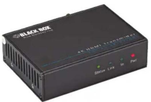
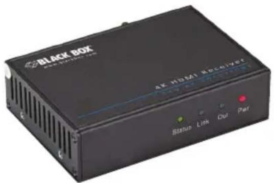
Trademarks Used in this Manual
Black Box and the Double Diamond logo are registered trademarks of BB Technologies, Inc.
Any other trademarks mentioned in this manual are acknowledged to be the property of the trademark owners.
FEDERAL COMMUNICATIONS COMMISSION AND INDUSTRY CANADA RADIO FREQUENCY INTERFERENCE STATEMENTS
This equipment generates, uses, and can radiate radio-frequency energy, and if not installed and used properly, that is, in strict accordance with the manufacturer's instructions, may cause interference to radio communication. It has been tested and found to comply with the limits for a Class A computing device in accordance with the specifications in Subpart B of Part 15 of FCC rules, which are designed to provide reasonable protection against such interference when the equipment is operated in a commercial environment. Operation of this equipment in a residential area is likely to cause interference, in which case the user at his own expense will be required to take whatever measures may be necessary to correct the interference.
Changes or modifications not expressly approved by the party responsible for compliance could void the user's authority to operate the equipment.
This digital apparatus does not exceed the Class A limits for radio noise emission from digital apparatus set out in the Radio Interference Regulation of Industry Canada.
For reliable operation of the equipment and personnel safety, follow the guidelines below for installation, use, and maintenance of the device.
- The system must be grounded properly. Do not use two-blade plugs and ensure the alternating power supply ranges from 100 to 240 VAC and 50 to 60 Hz.
- Do not put the control panel in an environment that is not within the its temperature tolerance.
- Because the switch's power generates heat when running, be sure the working environment is properly ventilated to avoid damage caused by equipment overheating.
- Turn off the general power switch in humid weather or when the control panel will be left unused for long time.
- Before operating, be sure that the alternating current wire is pulled out of the power supply.
- NEVER open the casing of the equipment, DO NOT repair it on your own. This might be harmful to persons or the equipment.
- DO NOT splash any liquids on or around the equipment.
Table of Contents
- Specifications 8
- Overview....10
2.1 Introduction.... 10
2.2 Features 10
2.3 What's Included.... 11
2.4 Hardware Description 11
2.4.1 Transmitter 12
2.4.2 Receiver 13
- System Connection 15
3.1 Usage Precautions....15
3.2 Connection Procedure 15
3.3 Application 16
3.4 Twisted-Pair Cable Connection 16
3.5 Co-Location Products 16
-
Troubleshooting and Maintenance....17
-
Specifications
| Input | |
| Input Signal Transmitter: | (1) HDMI,(1) IR,(1) RS-232;Receiver:(1) IR,(1) RJ-45,(1) RS-232 |
| Input Connector Transmitter: | (1) HDMI F,(1) 3.5-mm jack,(1) 3-pin screw terminal;Receiver:(1) 3.5-mm jack,(1) RJ-45,(1) 3-pin screw terminal |
| Video Signal HDMI 1.4 | |
| Audio Digital audio, transmit through HDMI audio | |
| Output | |
| Output Signal Transmitter: | (1) RJ-45,(1) IR,(1) RS-232;Receiver:(1) HDMI,(1) IR,(1) RS-232 |
| Output Connector Transmitter: | (1) RJ-45,(1) 3.5-mm jack,(1) 3-pin screw terminal;Receiver:(1) HDMI F,(1) 3.5-mm jack,(1) 3-pin screw terminal |
| Output (continued) | |
| Video Signal HDMI 1.4 | |
| General | |
| Resolution 800 x 600 @ | 60 Hz, 1024 x 768 @ 60 Hz, 1280 x 720 @ 60Hz, 1280 x 1024 @ 60Hz, 1366 x 768 @ 60Hz, 1600 x 1200 @ 60 Hz, 1920 x 1080 @ 60 Hz, 1920 x 1200 @ 60 Hz, 3D, 4K x 2K |
| Transmission Distance: 230 ft. (70 m); Mode: HDBaseT | |
| SNR >70 dB @ 10 MHz—100 MHz | |
| Bandwidth 10.2 Gbps | |
| THD <0.005% at 1 kHz | |
| HDMI Standard HDMI 1.4, 3D, HDCP | |
| Impedance 75 ohms | |
| Physical | |
| Dimensions 1.2"H x 4.3"W x 3"D (3 x 11 x 7.7 cm) | |
| Weight 1.1 lb. (0.5 kg) | |
| Power | |
| Power Supply Input: 100—240 VAC, 50/60 Hz; Output: 24-VDC, 1.25 A | |
| Consumption 9.6 W | |
| Environmental | |
| Operating Temperature | -14 to 104°F (-10 to +40°C) |
| Operating Humidity | 10 to 90% |
2. Overview
2.1 Introduction
The Video Extender —4K HDMI, IR, RS-232 Transmitter (AVS-HDB-TX) and Receiver (AVS-HDB-RX) is an HDMI/IR/RS232 twisted pair extender including a transmitter (AVS-HDB-TXT) and receiver (AVS-HDB-TXR). The AVS-HDB-TX uses HDBaseT technology to transmit an HDMI signal, and the maximum transmission distance is up to 230 feet (70 meters) over CAT5e/CAT6 cable. CEC, bi-directional RS-232 and IR control, and PoC are supported by the AVS-HDB-TX/AVS-HDB-RX extender pair.
2.2 Features
- Supports Full HD: Delivers resolutions including 800 x 600 @ 60 Hz, 1024 x 768 @ 60 Hz, 1280 x 720 @ 60Hz, 1280 x 1024 @ 60Hz, 1366 x 768 @ 60Hz, 1600 x 1200 @ 60 Hz, 1920 x 1080 @ 60 Hz, 1920 x 1200 @ 60 Hz, 3D, 4K × 2K
- Maximum transmission distance is up to 70 meters over a single CAT5e/CAT6 cable.
• High Bandwidth: 10.2 Gps. - HDTV Compatible, HDMI 1.4 and HDCP compliant.
• Supports PoC and CEC. - Connects to a display to transmit EDID and HPD signals continuously via a CAT5e cable.
- Uses HDBaseT technology.
- Uses bi-directional RS232/IR control.
• LED indicators show status. - Housed in a wall/table-mountable aluminum enclosure.
NOTE: Use a CAT5e cable with low impedance (shielded twisted pair should be well grounded) for proper transmission.
2.3 What's Included
Your package should include the following items. If anything is missing or damaged, contact Black Box Technical Support at 724-746-5500 or info@blackbox.com.
Transmitter (AVX-HDB-TX):
• Video Extender —4K HDMI, IR, RS-232 Transmitter (AVS-HDB-TX)
• (2) mounting brackets
• (4) rubber feet
• (4) screws
• (1) RS-232 cable
• (1) 24-VDC power adapter
• Video Extender —4K HDMI, IR, RS-232 Receiver (AVS-HDB-RX)
• (2) mounting brackets
• (4) rubber feet
• (4) screws
• (1) RS-232 cable
• (1) 24-VDC power adapter
To download the user manual from the Black Box Web site:
- Go to www.blackbox.com
- Enter the part number (AVS-HDB-TX or AVS-HDB-RX) in the search box:
- Click on the "Resources" tab on the product page, and select the document you wish to download.
2.4 Hardware Description
Figures 2-1 and 2-2 show the front and back panels of the transmitter. Table 2-1 describes its components.
Figures 2-3 and 2-4 show the front and back panels of the receiver. Table 2-2 describes its components.
2.4.1 4K HDMI, IR, RS-232 Transmitter (AVS-HDB-TX)
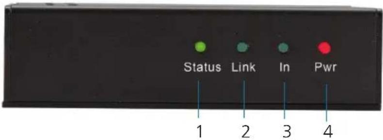
Figure 2-1. Transmitter front panel.
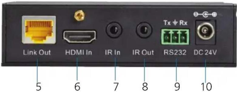
Figure 2-2. Transmitter back panel.
Table 2-1. Transmitter components.
| Number in Figure 2-1 or 2-2 | Component Description | |
| 1 | On LED | Blinks green when unit is working.Turns OFF when unit is not working. |
| 2 Link LED Twisted | pair status indicator: lights greenwhen the connection is good. | |
| 3 HDCP LED • Lights | green when the connected devicesupports HDCP.Blinks green whent he connected device does not support HDCP. | |
| 4 Power LED Lights | red when power is on. | |
| 5 RJ-45 connector | HDBT Out: Connects to the HDBT In port ofthe receiver via a CAT5e cable. | |
| 6 HDMI connector | HDMI in: Connects to the HDMI source. | |
| 7 IR In sensor Connects to the IR receiver to accept IR signalfrom the AVS-HDB-RX. | ||
| 8 | IR out sensor | Connects to the IR transmitter to receive IR signals from the AVS-HDB-RX. |
| 9 3-pin terminal | block | RS-232 serial port: connects to the control terminal and supports bidirectional RS-232 control. |
| 10 Barrel connector | Links to a 24-VDC | power supply.NOTE: The power supply is not required at the transmitter (AVS-HDB-TX if the receiver (AVS-HDB-RX) connects to a power supply. |
2.4.2 4K HDMI, IR, RS-232 Receiver (AVS-HDB-RX)
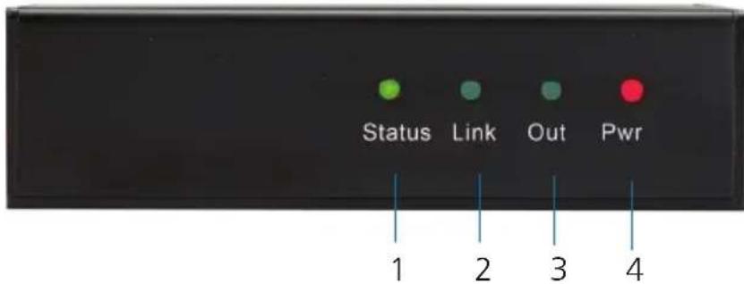
Figure 2-3. Receiver front panel.
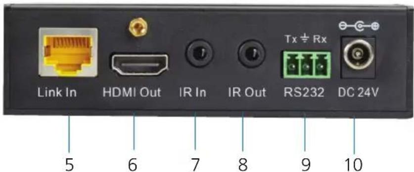
Figure 2-4. Receiver back panel.
Table 2-2. Receiver components.
| Number in Figure 2-3 or 2-4 | Component Description | |
| 1 | On LED | Blinks green when unit is working.Turns OFF when unit is not working. |
| 2 Link LED Twisted | pair status indicator: lights greenwhen the connection is good. | |
| 3 HDCP LED • Lights | green when the connected devicesupports HDCP.Blinks green whent he connected device does not support HDCP. | |
| 4 Power LED Lights | red when power is on. | |
| 5 RJ-45 connector | HDBT IN: Connectsto the HDBT Out port ofthe transmitter via a CAT5e cable. | |
| 6 HDMI connector | HDMI Out: Connectsto the HDMI display. | |
| 7 IR In sensor Connects to the IR receiver to send signal fromthe AVS-HDB-TX to the AVS-HDB-RX. | ||
| 8 | IR out sensor | Connects to the IR transmitter to receive IRsignal from the AVS-HDB-RX. |
| 9 3-pin terminal | block | RS-232 serial port: connects to the controlterminal and supports bidirectional RS-232control. |
| 10 | Barrel connector | Links to a 24-VDC power supply.NOTE: The power supply is not required at thereceiver (AVS-HDB-RX if the transmitter(AVS-HDB-TX) connects to a powersupply. |
3. System Connection
3.1 Usage Precautions
-
Install the system in a clean environment that has a proper temperature and humidity.
-
Make sure that all f the power switches, plugs, sockets and power cords are insulated and safe.
-
Connect all devices before powering on.
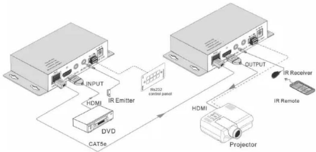
flowchart
graph TD
    A["Device 1"] -->|INPUT| B["IR Emitter"]
    B --> C["HDMI"]
    C --> D["DVD"]
    D --> E["CAT5e"]
    E --> F["Output"]
    F --> G["IR Receiver"]
    G --> H["Projector"]
    H --> I["HDMI"]
    I --> J["IR Remote"]
    J --> K["Control Panel Rs232"]
    style A fill:#f9f,stroke:#333
    style B fill:#ccf,stroke:#333
    style C fill:#cfc,stroke:#333
    style D fill:#fcc,stroke:#333
    style E fill:#cff,stroke:#333
    style F fill:#ffc,stroke:#333
    style G fill:#fcc,stroke:#333
    style H fill:#ffc,stroke:#333
    style I fill:#cfc,stroke:#333
    style J fill:#fcc,stroke:#333
    style K fill:#ffc,stroke:#333
Figure 3-1. Connections.
3.2 Connection Procedure
Step 1: Connect an HDMI source (such as a Blu-ray™ DVD) to the HDMI IN port of AVS-HDB-TX with HDMI cable.
Step 2: Connect the HDBT OUT port of AVS-HDB-TX to the HDBT IN port of the AVS-HDB-RX through a CAT5e/CAT6 cable.
Step 3: Connect an HDMI display (such as HDTV) to the HDMI OUT port of the AVS-HDB-RX with HDMI cable.
Step 4: Both AVS-HDB-TX and AVS-HDB-RX have IR IN and OUT. When one end is used as an IR receiver, the other end will be used as an IR transmitter.
For example: When "IR IN" of AVS-HDB-TX connects to an IR receiver, the IR transmitter must be connected to "IR OUT" of the AVS-HDB-RX.
Step 5: Connect the RS-232 port of the devices to control to the receiver or the transmitter.
Step 6: Connect the 24-VDC power adapter to either the transmitter or receiver.
NOTE: The power supply is not required at the transmitter (AVS-HDB-TX if the receiver (AVS-HDB-RX) connects to a power supply
The power supply is not required at the receiver (AVS-HDB-RX if the transmitter (AVS-HDB-TX) connects to a power supply.
3.3 Application
Use the AVS-HDB-TX and AVS-HDB-RX for computer monitoring, conference rooms, large-screen displays, television, education applications and more.
3.4 Twisted-Pair Cable Connection
The twisted pair used with the extender MUST be a straight-through cable. The connectors can be T568A or T568B, but both sides must be the same.
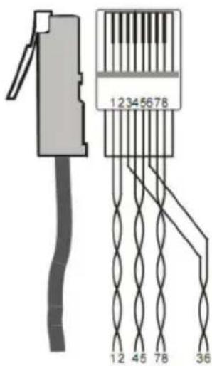
Figure 3-2. Cable pinout diagram.
NOTE: Cable connectors must be metal, and the shielded layer must be connected to the connector's metal shell to ground the cable.
3.5 Extending Transmission Distance
The AVS-HDB-TX and AVS-HDB-RX extenders work with the Multi-Format Video Scaler with Extension - 5-Port (AVSC-5DA1-HDB) to extend the transmission distance of an HDMI/IR/RS-232 signal.
4. Troubleshooting and Maintenance
Problems/Causes/Solutions
Table 4-1. Problems/Causes/Solutions.
| Problems Causes Solutions | ||
| Output images in display appear with ghost. | Incorrect setting on the display. | Check the display's setting. |
| Bad quality cable Try another high-quality connection cable. | ||
| No output image when switching. | No signal at the input/output end. | Check with and oscilloscope or multimeter to see if there is a problem at the input/output end. |
| Failed or loose connection. | Make sure the connection is good. | |
| The extender is broken. | Contact Black Box Technical Support at 724-746-5500 or info@blackbox.com. | |
| Cannot control the device by a PC through the RS-232 port. | Wrong RS-232 communications parameters. | Make sure the RS-232 communication parameters are correct. |
| The extender is broken. | Contact Black Box Technical Support at 724-746-5500 or info@blackbox.com. | |
| Static becomes stronger when connecting the video connectors. | Bad grounding. Check the grounding and make sure it is connected well. | |
| Cannot control the device via RS-232/IR. | The extender is broken. | Contact Black Box Technical Support at 724-746-5500 or info@blackbox.com. |
If your problem persists after you follow the above troubleshooting steps, contact Black Box Technical Support at 724-746-5500 or info@blackbox.com.
Black Box Tech Support: FREE! Live. 24/7.
Tech support the way it should be.

natural_image
Close-up portrait of a smiling man wearing a headset (no text or symbols visible)Great tech support is just 60 seconds away at 724-746-5500 or blackbox.com.

BLACK BOX®
About Black Box
Black Box provides an extensive range of networking and infrastructure products. You'll find everything from cabinets and racks and power and surge protection products to media converters and Ethernet switches all supported by free, live 24/7 Tech support available in 60 seconds or less.
© Copyright 2015. Black Box Corporation. All rights reserved. Black Box ^® and the Double Diamond logo are registered trademarks of BB Technologies, Inc. Any third-party trademarks appearing in this manual are acknowledged to be the property of their respective owners.
AVS-HDB-TX, version 1
- User Manual
- FEDERAL COMMUNICATIONS COMMISSION AND INDUSTRY CANADA RADIO FREQUENCY INTERFERENCE STATEMENTS
- Table of Contents
- Overview
- Introduction
- Features
- What's Included
- Hardware Description
- 4K HDMI, IR, RS-232 Transmitter (AVS-HDB-TX)
- 4K HDMI, IR, RS-232 Receiver (AVS-HDB-RX)
- System Connection
- Usage Precautions
- Connection Procedure
- Application
- Twisted-Pair Cable Connection
- Extending Transmission Distance
- Troubleshooting and Maintenance
- Problems/Causes/Solutions
- BLACK BOX®
- About Black Box
Brand : Black Box
Model : AVS-HDB-TX
Category : AV Extender