AC1070A - AV Extender Black Box - Free user manual and instructions
Find the device manual for free AC1070A Black Box in PDF.


| Product Type | 3-Channel DVI Extender (Triple DVI Extender via Fiberoptic Cable) |
| Model | AC1070A |
| Brand | Black Box |
| Transmission Medium | MTP®/MPO 12-fiber multimode fiberoptic cable |
| Number of Channels | 3 |
| Max Resolution (Digital) | 1920 x 1200 @ 60 Hz |
| Max Resolution (Analog) | 1600 x 1200 @ 60 Hz |
| Transmission Distance (50 µm fiber) | Up to 400 m |
| Transmission Distance (62.5 µm fiber) | Up to 300 m |
| Transmission Rate | 3 x 165 MHz (3 x 3.6 Gbps) |
| Input Interfaces | 3 x DVI-I (digital and analog) |
| Output Interfaces (Receiver) | 3 x DVI-D (digital) |
| Local Output (Transmitter) | 3 x DVI-I (analog output only with analog input) |
| Configuration Interface | RS232 via RJ45 |
| Power Supply | 100–240 V AC, 8 VA per unit (Transmitter and Receiver) |
| Dimensions (W x D x H) | 219 x 170 x 43 mm |
| Casing | Powder-coated steel, black (RAL 9005) |
| Included Accessories | 2 power cables, 2 DVI/DVI cables (2 m), 1 VGA/DVI cable (2 m), 1 serial RJ45/RS232 cable, installation CD, manual |
| Compliance | Class 1 Laser, FCC Class A, CE |
| Maintenance | Maintenance-free, no user-serviceable parts |
| Safety Features | Laser Class 1, ensure ventilation not blocked, power off during installation |
Frequently Asked Questions - AC1070A Black Box
User questions about AC1070A Black Box
0 question about this device. Answer the ones you know or ask your own.
Ask a new question about this device
Download the instructions for your AV Extender in PDF format for free! Find your manual AC1070A - Black Box and take your electronic device back in hand. On this page are published all the documents necessary for the use of your device. AC1070A by Black Box.
USER MANUAL AC1070A Black Box
3-Channel DVI Extender
Triple - DVI - Extender using a fi beroptic cable
Installation and Operation Manual
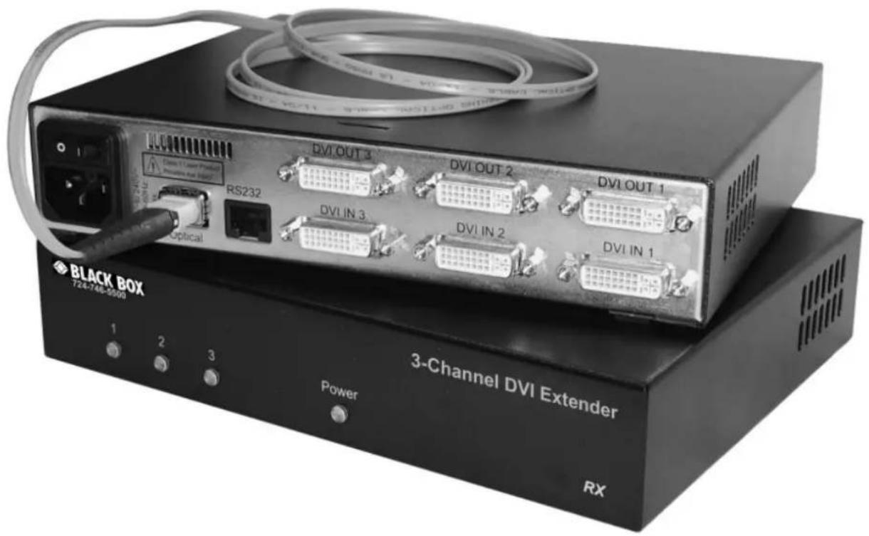
3-Channel DVI Extender
Triple - DVI - Extender using a fi beroptic cable

BLACK BOX
© Copyright BLACK BOX Corp.
Version 1.0 October 1, 2005
TRADEMARKS USED IN THIS MANUAL
BLACK BOX and the Double Diamond logo are registered trademarks, and 3-Channel DVI Extender is a trademark, of BB Technologies, Inc.
Any other trademarks mentioned in this manual are acknowledged to be the property of the trademark owners.
Black Box Corporation 1000 Park Drive Lawrence, PA 15055-1018
Phone: 724-746-5500 Web: www.blackbox.com
Thank you for choosing the BLACK BOX 3-Channel DVI Extender.
Its use of fiberoptic cables permits transmission of video signals without any compression.
This ensures completely loss-free data transmissions with full video refresh rates.
The result:
Excellent image quality, even at high resolutions!
You will not only enjoy the benefits of longer transmission distances, but also make your transmission routes completely insensitive to electromagnetic interference.
In addition, you ensure overvoltage protection of your transmission routes.
The BLACK BOX 3-Channel DVI Extender transmits three DVI-I interfaces (digital/analog) in real time to remote monitors, displays, video projectors and other output devices with digital interfaces.
While both digital and analog video signals can be supplied to the input side, the output ports on the receiving side are all digital.
An MTP®/MPO 12-fiber multimode fiberoptic cable is used as the transmission medium, facilitating achievement of 3 x 3.6 Gbps data rates.
Depending on the type of fibers used in the fiberoptic cable (50 or 62.5 m), distances of up to 400 meters can be covered.
Your 3-Channel DVI Extender supplies three output devices via one joint fi beroptic cable.
The 3-Channel DVI Extender supports video resolutions up to 1920 x 1200 px @ 60 Hz with digital video input and up to 1600 x 1200 px @ 60 Hz with analog video input.
Optionally, local output devices can also be connected to the transmitter (source).
INTRODUCTION
Device configuration is based on the serial RS232 interface.
Firmware upgrades are also handled via this connector.
The 3-Channel DVI Extender can be used not only in heavy-duty industrial environments, but also in the media sector, the television and entertainment industries, training and education centers and many other application areas in the visualization business.
The 3-Channel DVI Extender transmission system consists of the 3-Channel DVI Extender TX transmitter unit and the 3-Channel DVI Extender RX receiver unit.
Both devices are delivered as desktop versions.
TABLE OF CONTENTS
INTRODUCTION 3
TABLE OF CONTENTS 5
SAFETY GUIDELINES 6
DELIVERABLES 7
DEVICE CONNECTIONS 8
EXPLANATION OF CONNECTIONS 9
HARDWARE INSTALLATION 10
INSTALLATION PLAN 11
DEVICE CONFIGURATION PROGRAM INSTALLATION 12
PROGRAM INSTALLATION 12
SETTINGS 13
CONFIGURATION 14
PROGRAM START 14
NAVIGATION 15
EDID INTERNAL AND DEFAULT 24
EXTERNAL 25
HELP ABOUT AND CONTACT 26
FIRMWARE UPDATE 27
TECHNICAL SPECIFICATIONS 29
ACCESSORIES 30
SERVICE INFORMATION 31
TECHNICAL SUPPORT 32
NOM-STATEMENT 33
DECLARATION OF CONFORMITY 35
FCC DECLARATION 35
SAFETY GUIDELINES
CAUTION: LASER
Your 3-Channel DVI Extender is a Class 1 laser product.
There is a risk of damaging your eyesight if you disregard this safety information!
Even if they are not in use, the fiberoptic connections of the modules must be sealed either with a MTP®/MPO cable connector or a dust cap.
Please ensure that the power supply is switched off before you disconnect or connect fi beroptic cables.
Both the 3-Channel DVI Extender TX transmitter and the 3-Channel DVI Extender RX receiver are connected to the power supply system.
Please observe the usual safety regulations for handling devices connected to a power supply system.
Both devices have built-in fans. Please ensure that there is a reliable air supply on both sides and the air outlet on the rear panel are not blocked.
Your desktop devices should never be placed on the floor between cables.
Moisture and dust will affect the reliable functioning of your 3-Channel DVI Extender.
These devices are maintenance-free. Never open the device panels. There are no settings that need to be adjusted inside the casing.
Please contact BLACK BOX's Technical Support for troubleshooting purposes (page 31).
Please use the list below to verify that all parts have been delivered.
The following components are included:
• 1 3-Channel DVI Extender TX transmitter unit
• 1 3-Channel DVI Extender RX receiver unit
• 2 power cables
• 2 DVI / DVI video cables, 2.0 meters, for the transmitter unit
• 1 VGA / DVI video cable, 2.0 meters, for the transmitter unit
• 1 serial RJ45 / RS232 cable
• 1 installation CD for Windows
• 1 installation and operation manual
The MTP®/MPO fiberoptic cables supplied to you by BLACK BOX are prefabricated and cut to the desired custom lengths for a maximum range of up to 400 meters.
Please see page 30 for further details and more optional accessories.
DEVICE CONNECTIONS
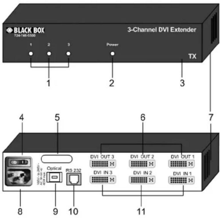
3-Channel DVI Extender TX transmitter unit Front panel
3-Channel DVI Extender TX transmitter unit Rear panel
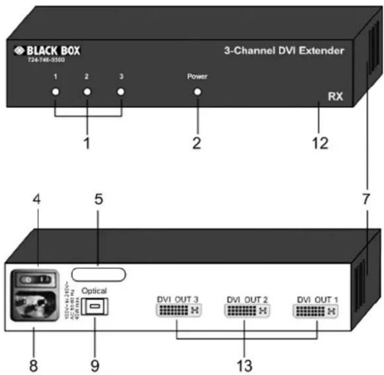
3-Channel DVI Extender RX receiver unit Front panel
3-Channel DVI Extender RX receiver unit Rear panel
EXPLANATION OF CONNECTIONS
1 LED Lights up when the video signal is active
2 LED Power Lights up when the power supply is active
3 3-Channel DVI Extender TX Label identifying the TX transmitter unit
4 Switch Switches the power supply on and off
5 Air outlet Ventilation duct where the heated outgoing air is vented. Please do not cover!
6 DVI OUT 1-3 Optional local connections for linking video output devices to the TX transmitter unit
7 Air intake Ventilation duct for air intake in on both sides. Please do not cover!
8 Power connector For connecting the supplied power cable
9 Optical MTP®/MPO port for connecting the fi beroptic cable with MTP®/MPO female / female plugs
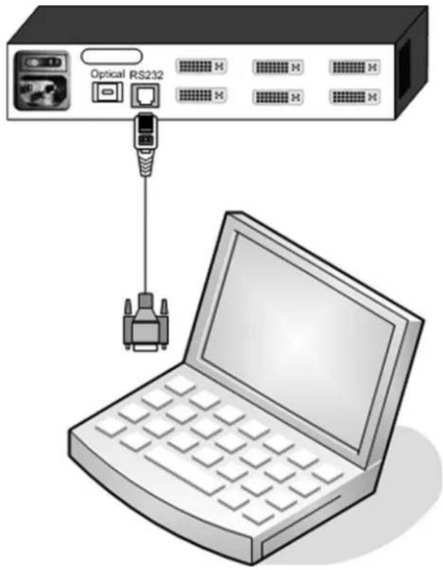
10 RS232 RJ45 port for connecting the serial cable for device configuration and firmware updates
11 DVI IN 1-3 Input port for the video signal Connection to the video source Importing EDID (page 25) Connecting cable included in deliverables
12 3-Channel DVI Extender RX Label identifying the RX receiver unit
13 DVI OUT 1-3 Output port for the digital video signal Connection to video output device via connecting cable
HARDWARE INSTALLATION
Safety information:
Please ensure that the power is switched off when installing any device!
Laser Class 1 devices can damage your eyesight!
Installation steps:
-
Select a suitable location for the 3-Channel DVI Extender TX transmitter unit and the 3-Channel DVI Extender RX receiver unit.
Please see page 30 for information about optional accessories.
Please comply with the safety guidelines on page 6. -
Connect your 3-Channel DVI Extender TX transmitter unit to the video signal sources via the respective DVI IN input, using the enclosed DVI cables.
-
Connect your 3-Channel DVI Extender RX receiver unit to the video output devices via the respective DVI OUT output, using the DVI cables.
-
Connect your 3-Channel DVI Extender TX transmitter unit to your 3-Channel DVI Extender RX receiver unit via the MTP®/MPO plug labeled "Optical", using an MTP®/MPO 12-fiber multimode fiberoptic cable.
Please make sure that both connectors lock in place.
The necessary cables are available from BLACK BOX (see page 30).
-
Please check again that all cables, plugs and screw connections have been connected properly.
-
Connect the transmitter and receiver to the power supply and switch on both devices.
-
Power up your computers or video output sources.
-
Use the CONFDEV device configuration program (see Page 12 et seq.) for configuration.
Please note:
BLACK BOX also guarantees interference-free operation for video cable lengths of 3 to 5 meters.
If you experience any interference, please check the quality of the video cables used, the video resolution settings and the quality of the devices connected.
If the distance between the video output device and your 3-Channel DVI Extender RX receiver unit exceeds 5 meters, BLACK BOX offers an extension kit supporting the use of longer video cables (page 30).
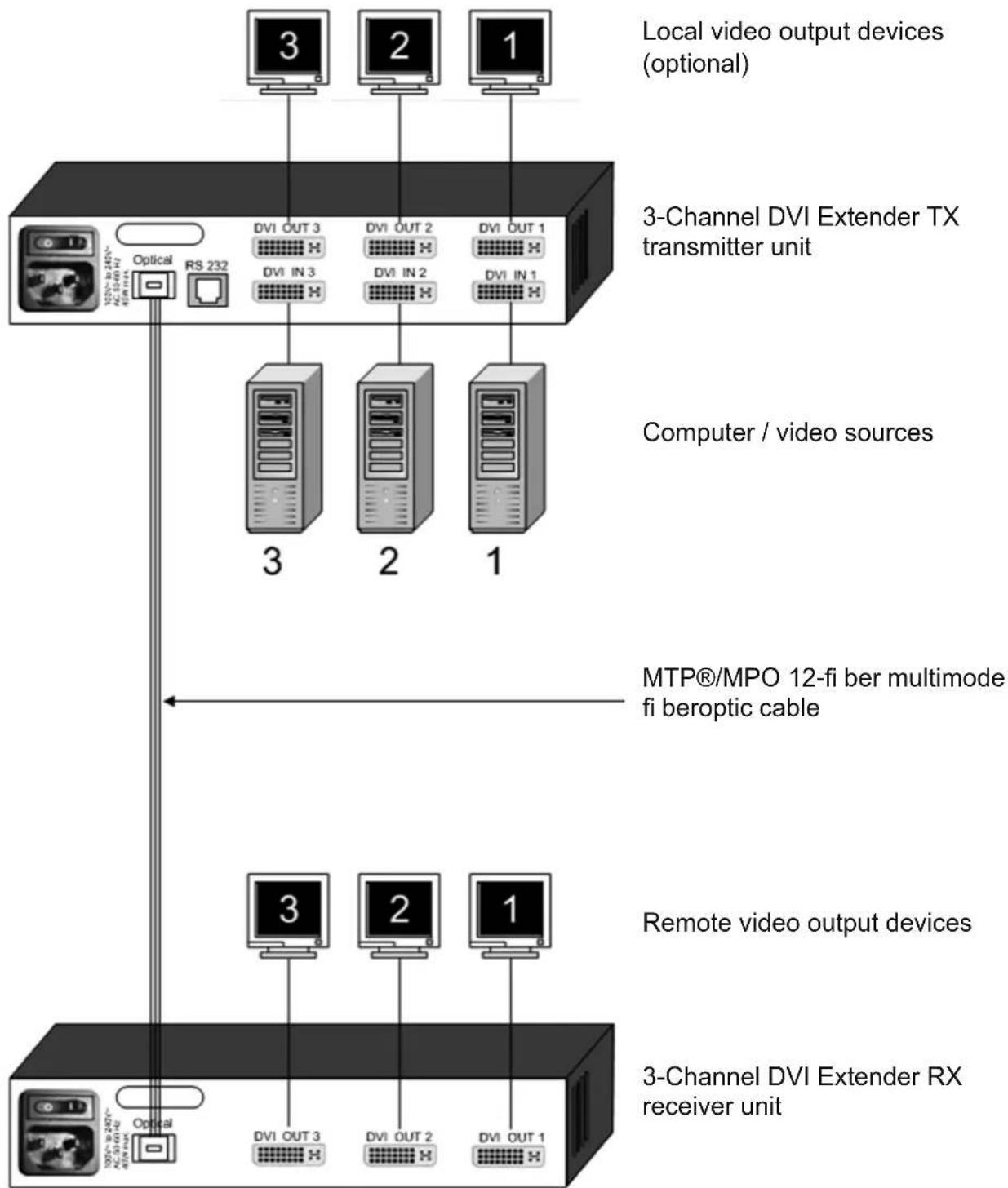
flowchart
graph TD
    A["Local video output devices (optional)"] --> B["3-Channel DVI Extender TX transmitter unit"]
    B --> C["Computer / video sources"]
    C --> D["MTP®/MPO 12-fi ber multimode fi beroptic cable"]
    D --> E["Remote video output devices"]
    E --> F["3-Channel DVI Extender RX receiver unit"]
    F --> G["Optical"]
    G --> H["Optical"]
    style A fill:#f9f,stroke:#333
    style B fill:#ccf,stroke:#333
    style C fill:#cfc,stroke:#333
    style D fill:#fcc,stroke:#333
    style E fill:#cff,stroke:#333
    style F fill:#ffc,stroke:#333
DEVICE CONFIGURATION PROGRAM INSTALLATION
For the installation of the CONFDEV device configuration software, you need:
- a computer running the Windows operating system with one available RS232 COM port
- your 3-Channel DVI Extender TX transmitter unit
- the installation CD (included in deliverables)
• one serial cable (included in deliverables)
Please comply with the following installation steps:
-
Use the serial cable to connect the COM port on your computer to the RJ45 port on the 3-Channel DVI Extender TX.
-
Switch on the power supply of your 3-Channel DVI Extender TX.
-
Insert the installation CD.
-
Follow the installation instructions on the screen.
-
The symbol of the CONFDEV device configuration program will appear on the desktop:
-
Start the device configuration program by clicking on the CONFDEV icon.
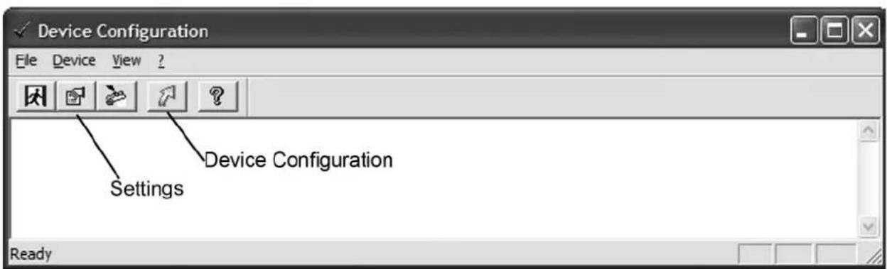
The device configuration program window will now appear on your screen:
DEVICE CONFIGURATION PROGRAM INSTALLATION
SETTINGS
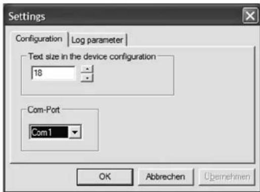
Communication settings:
The default COM port is COM 1.
If you have connected the 3-Channel DVI Extender TX to a different COM port, please adjust this setting accordingly.
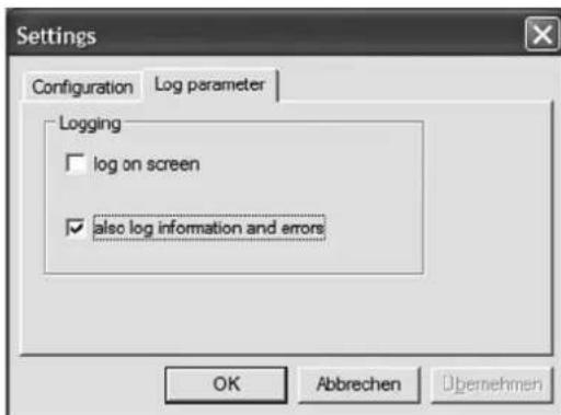
Log parameters:
You can select custom settings here. BLACK BOX recommends using the default settings.
Start configuration:
Start the configuration process by clicking on the green arrow.
Once the screen shown on the right appears, you have access to the configuration of your 3-Channel DVI Extender TX.
Follow the instructions on page 14 et seq.
CONFIGURATION
PROGRAM START
- Connect your configuration computer to your 3-Channel DVI Extender TX transmitter unit via the serial cable, as described on pages 12 and 13.
- Start the device configuration program by clicking on the CONFDEV icon.
- Click on the green arrow icon (see figure on the bottom of page 12) in the device configuration program window to call up the configuration of your 3-Channel DVI Extender TX.
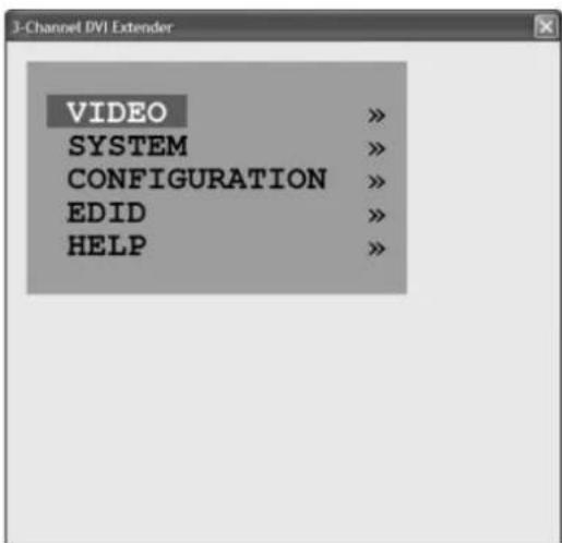
The BLACK BOX / 3-Channel DVI Extender main configuration window is displayed:
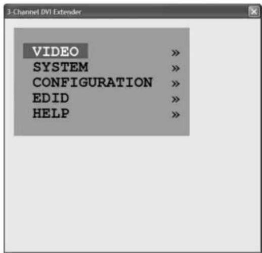
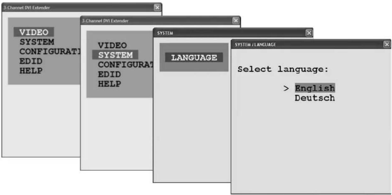
Instead of ENGLISH - the default setting - you can select also GERMAN as your language.
NAVIGATION
You can operate the configuration program with the help of the following keys or entries:
Cursor down = move down in the menu
Cursor up = move up in the menu
Right cursor, + = edit value, increase
Left cursor, - = edit value, decrease
Return/Enter = select menu item
ESC = return to previous menu
Enter first letter
of a menu item = select the respective menu item
CONFIGURATION
The configuration procedure of the 3-Channel DVI Extender is explained in detail below.
This page provides you with a general overview of the individual menu items and sub-menu items.
IMPORTANT NOTE:
Please see page 25 for information about EDID.
Please import the key data of your video output devices via the DVI IN inputs of your 3-Channel DVI Extender.
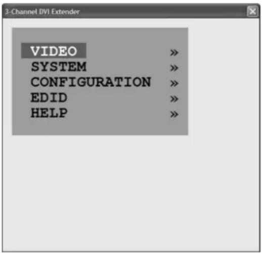
BRIEF CONFIGURATION OVERVIEW
Main window Sub-window Possible settings
VIDEO VIDEO INPUT Display of video input resolution DVI, VGA or VGA/DVI setting
BRIGHTNESS Adjustment for analog input signal
CONTRAST Adjustment for analog input signal
HORIZ POSITION Manual setting of horizontal
screen position
VERT POSITION Manual setting of vertical screen position
SCREEN WIDTH Screen width of analog input signal
PHASE Phase of the analog input signal
SYSTEM LANGUAGE English or German
CONFIGURATION FACTORY RESET Restore factory default settings
EDID CH 1 / INTERNAL 1 Current EDID (1, 2, or 3 per channel)
CH 1 / EXTERNAL 1 Import EDID via DVI IN 1
CH 1 / DEFAULT 1 Restore BLACK BOX default EDID
HELP ABOUT Revision level – firmware / hardware
CONTACT Manufacturer information
VIDEO INPUT
The VIDEO OSD menu is subdivided into seven sections. With the exception of the first item (VIDEO INPUT), this sub-menu contains settings for analog signals.
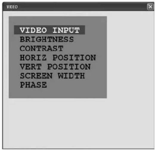
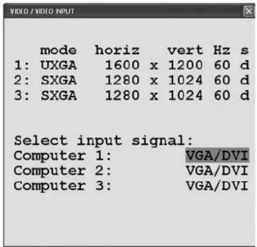
The top section of the VIDEO INPUT window shows the three video formats available for the input signals.
Column S shows the input signal type: a = analog
$$ \begin{array}{l l l l l} \text {d} & = & \text {digital} \ \text {g} & = & \text {sync on green} \ \text {c} & = & \text {composite sync} \end{array} $$
The video signal transmitted can be selected in the bottom section of the window.
VGA Analog signal DVI Digital signal
VGA / DVI Automatic selection: if both an analog and a digital signal are available, the analog VGA signal is transmitted. If only DVI is available, DVI is transmitted.
IMPORTANT NOTE:
Please observe the effect your settings in the OSD menu have on your video output devices.
If the output device is at a very remote location and no one is available to help you to observe the changes, you can also connect the output device directly to the respective DVI OUT port of your 3-Channel DVI Extender TX transmitter unit.
CONFIGURATION
VIDEO INPUT
All modes up to WUXGA 60 (1920 x 1200) are transmitted in the case of digital signals. If an unknown digital video mode is transmitted, the resolution will be displayed as “DVI transparent”.
The following analog video signals are recognized and transmitted:
| Mode | (pixel) | (Hz) | Resolution | Refresh rate |
| CGA | 640 x 350 | 85 | ||
| CGA | 640 x 400 | 85 | ||
| EGA | 720 x 400 | 70 | ||
| EGA | 720 x 400 | 85 | ||
| VGA | 640 x 480 | 60 | ||
| VGA | 640 x 480 | 72 | ||
| VGA | 640 x 480 | 75 | ||
| VGA | 640 x 480 | 85 | ||
| SVGA | 800 x 600 | 56 | ||
| SVGA | 800 x 600 | 60 | ||
| SVGA | 800 x 600 | 72 | ||
| SVGA | 800 x 600 | 75 | ||
| SVGA | 800 x 600 | 85 | ||
| XGA | 1024 x 768 | 60 | ||
| XGA | 1024 x 768 | 70 | ||
| XGA | 1024 x 768 | 75 | ||
| XGA | 1024 x 768 | 85 | ||
| XGA/B | 1152 x 864 | 75 | ||
| SUN | 1152 x 900 | 66 | ||
| WXGA 60 | 1280 x 768 | 60 | ||
| UWXGA 60 | 1280 x 960 | 60 | ||
| UWXGA 85 | 1280 x 960 | 85 | ||
| SXGA 50 | 1280 x 1024 | 50 | ||
| SXGA 60 | 1280 x 1024 | 60 | ||
| SXGA 72 | 1280 x 1024 | 72 | ||
| SXGA 75 | 1280 x 1024 | 75 | ||
| SXGA 85 | 1280 x 1024 | 85 | ||
| SGI | 1600 x 1024 | 60 | ||
| UXGA 50 | 1600 x 1200 | 50 | ||
| UXGA 60 | 1600 x 1200 | 60 |
BRIGHTNESS
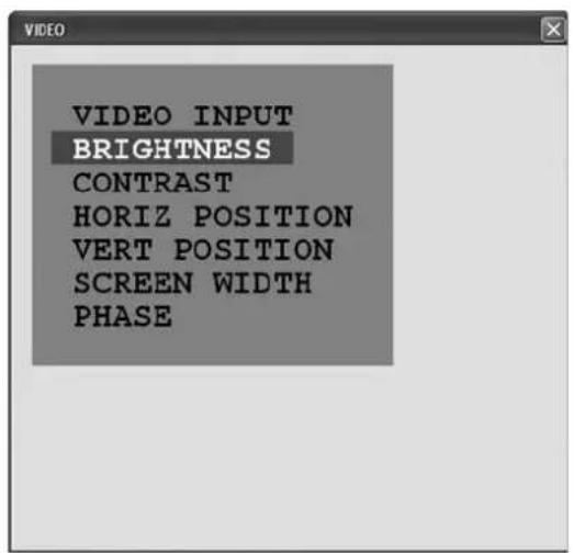
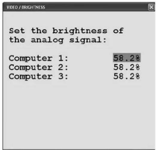
For analog signal input, you can adjust the brightness within a range 0 to 100% in this section.
The factory default value is 58.2%.
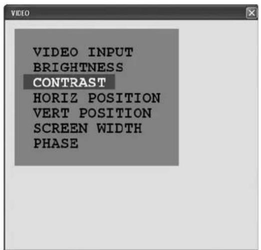
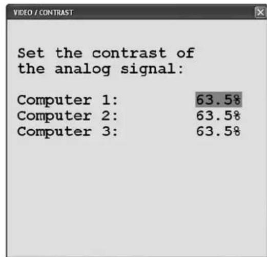
CONTRAST
For analog signal input, you can adjust the contrast within a range 0 to 100% in this section.
The factory default value is 63.5%.
CONFIGURATION
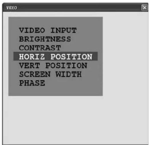
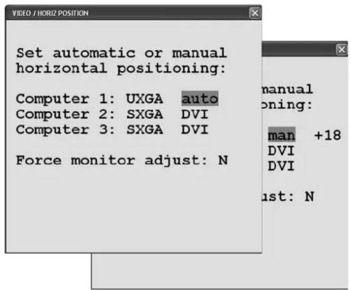
HORIZONTAL POSITION
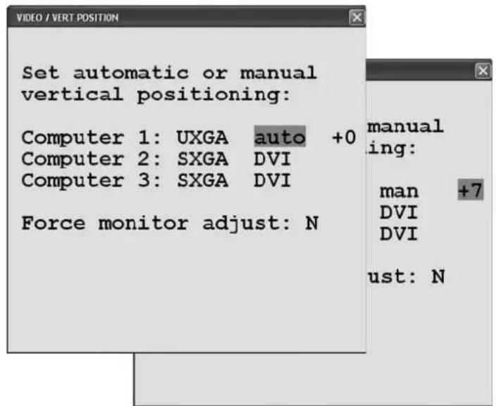
If the image position of the analog signal is not correct, use the cursors to switch from “auto” to “man” (manual) and adjust the horizontal position within a range from -40 to +40. If your output device responds very slowly to the changes, select “Force monitor adjust” to ensure that any change to the image position briefly interrupts the video signal.
VERTICAL POSITION
Use the cursors to switch from “auto” to “man” (manual) and adjust the vertical position within a range from -20 to +20. If your output device responds very slowly to the changes, select “Force monitor adjust” to ensure that any change to the image position briefly interrupts the video signal.
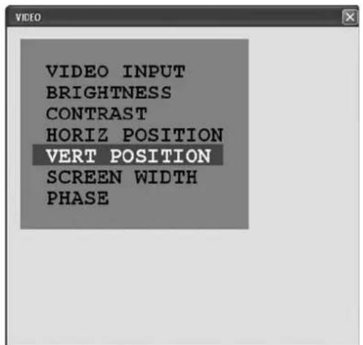
SCREEN WIDTH
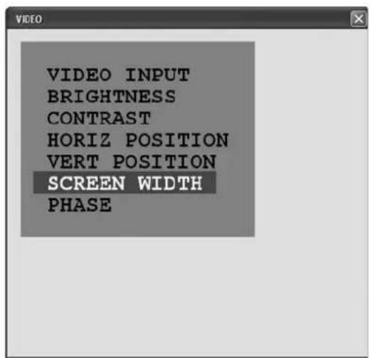
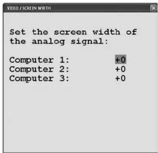
The image width (number of horizontal pixels) is usually determined by the VESA standard.
If your image appears blurred, you can improve image quality by adjusting it within a range of -16 to +16.
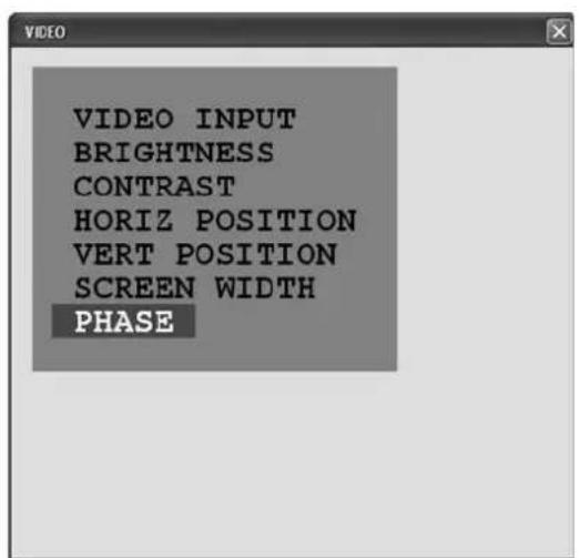
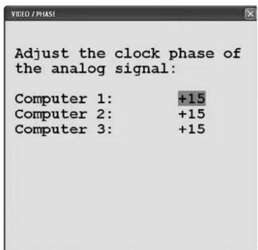
PHASE
Unfavorable analog phasing (pixel scanning time) may lead to degradation of image quality in the form of blurring, poor contrast or faded writing.
Try to optimize your image within a range from -16 to +15.
CONFIGURATION
SYSTEM
You can use this menu item to set the menu language.
As the OSD menu screenshot shows, you can choose between English (the default language) or German.
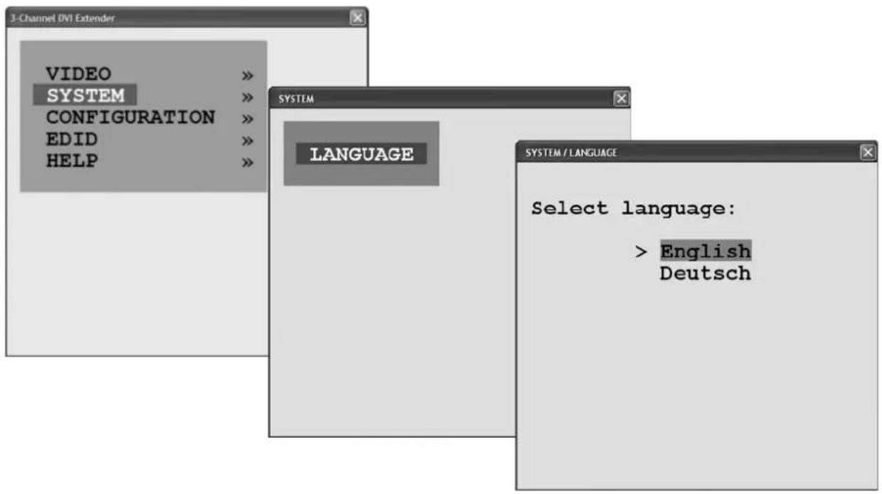
Please select your preferred language.
Confir rm your selection by pressing Return or Enter.
The OSD menu will now switch to the language selected.
FACTORY RESET
If you wish to restore the factory default settings on your 3-Channel DVI Extender, please follow the steps shown in the screenshots.
Confirm with Enter or Return to change from user settings back to factory default settings. The EDID (see pages 24-25) will not be reset!
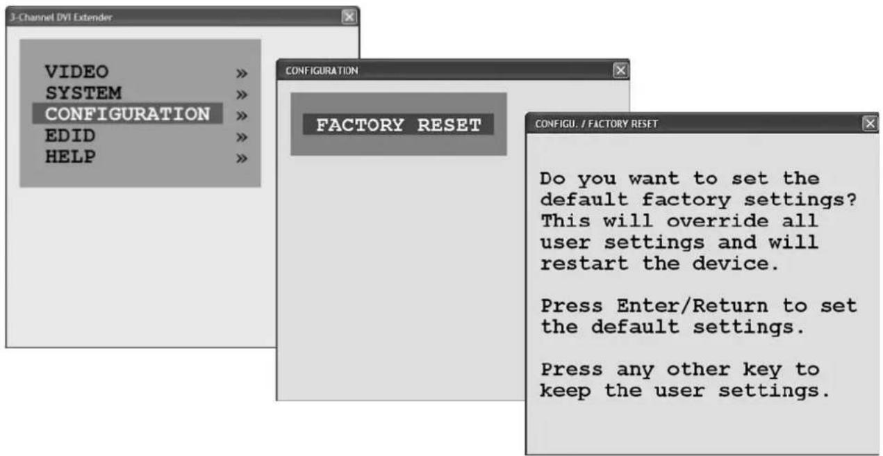
The following message appears when you reset the factory default settings:
Setting default settings
The VIDEO menu is reset to the following values:
VIDEO VIDEO INPUT = VGA / DVI (all channels)
BRIGHTNESS = 58.2% (all channels)
CONTRAST = 63.5% (all channels)
HORIZ POSITION = auto (all channels)
VERT POSITION = auto (all channels)
SCREEN WIDTH = +0 (all channels)
PHASE = -16 (all channels)
CONFIGURATION
EDID
(extended display identifi cation data)
Video output devices transmit their EDID to the connected graphics card via the Display Data Channel (DDC).
Your 3-Channel DVI Extender TX uses all twelve optical fibers in your fiberoptic cable exclusively for signal transmission. Therefore it is not possible to transmit the EDID of the monitor from the 3-Channel DVI Extender RX back to the computer, connected to the 3-Channel DVI Extender TX.
The graphics cards receive the required EDID parameters from an EEPROM containing the default settings for each DVI-IN input on your 3-Channel DVI Extender TX.
BLACK BOX recommends working with the actual EDID of your video output devices.
EDID INTERNAL and DEFAULT
In the factory default settings, the default BLACK BOX EDID is preset on all three DVI IN input ports under INTERNAL:
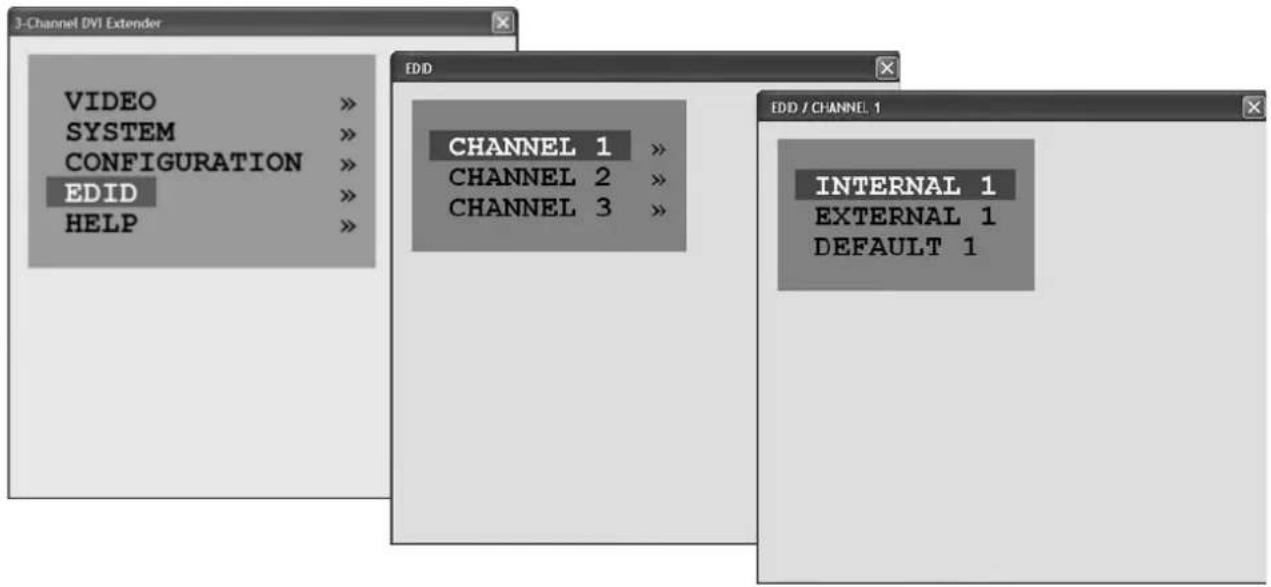
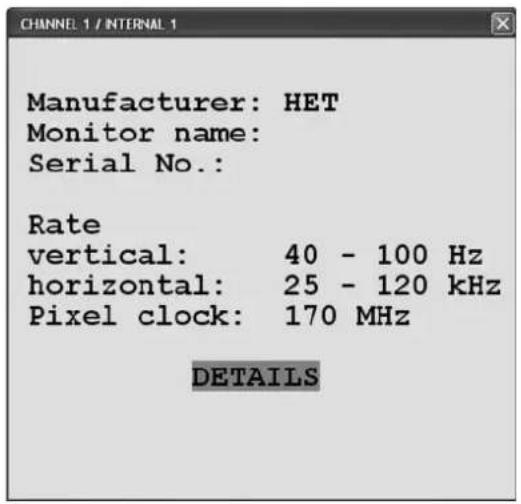
The default settings shown here should be overwritten with the actual EDIDs from the video output devices via EXTERNAL (page 25).
NOTE:
You can reset the default EDID via DEFAULT. Use the STORE command to save the default settings in INTERNAL.
The DETAILS sub-menu is used by BLACK BOX for error diagnosis.
EDID EXTERNAL IMPORTANT!
Move your 3-Channel DVI Extender transmitter unit to the video output devices and connect the respective lower DVI IN port to the DVI cable on the output device.
When you switch on your 3-Channel DVI Extender (after connecting the power supply cable), the EDID of the connected video output device is automatically read by the 3-Channel DVI Extender and saved in an EEPROM for each DVI IN port. The respective LED will flash four times during the scanning process. You can then switch off your 3-Channel DVI Extender.
Once you have repeated this procedure individually or simultaneously for all three channels, the original EDID of the output device will be available at each channel. The EXTERNAL function described below has thus been automated. However, menu-based import of the individual values is also possible via EXTERNAL 1 - 3:
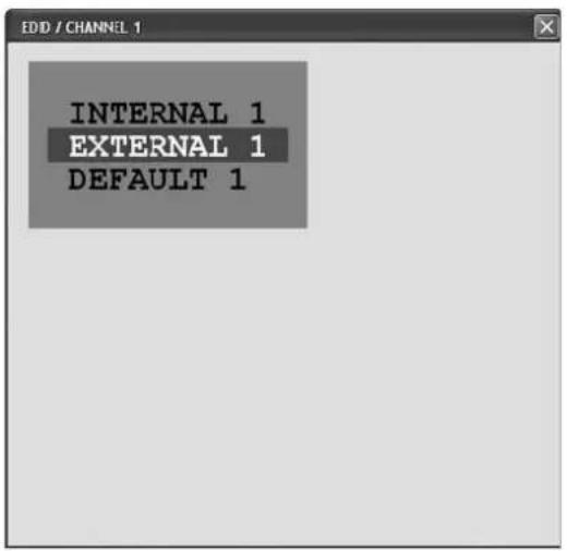
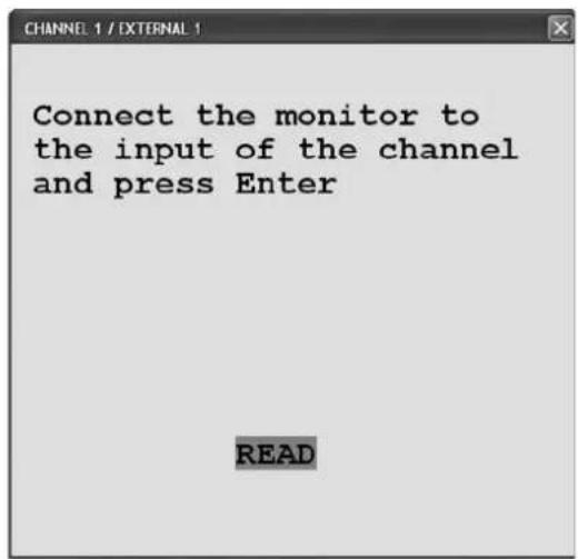
Once the data has been read out successfully, you can reconnect your 3-Channel DVI Extender TX to the video signal sources (see page 10).
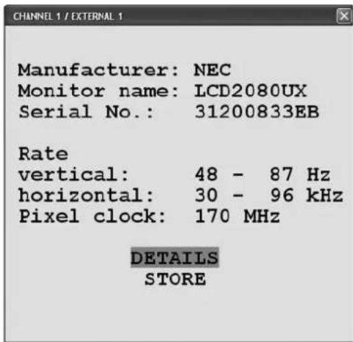
As described on page 24, you will now find the original EDID of your video output device 1 under EDID / CHANNEL 1 / INTERNAL 1:
An NEC MultiSync LCD 2080UX+ was recognized in the example shown here.
If you exchange your video output devices, please remember to import the EDID of the newly connected devices in the manner described above.
CONFIGURATION
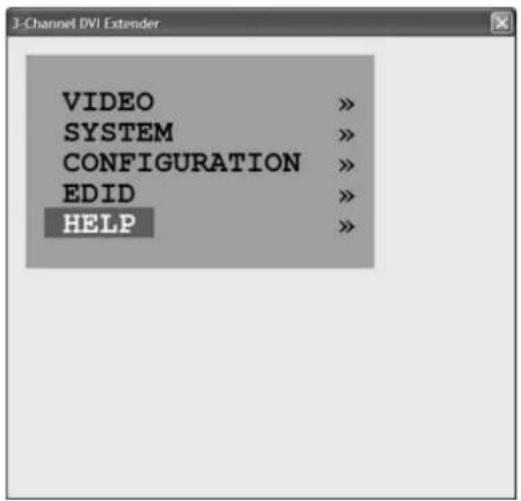
HELP
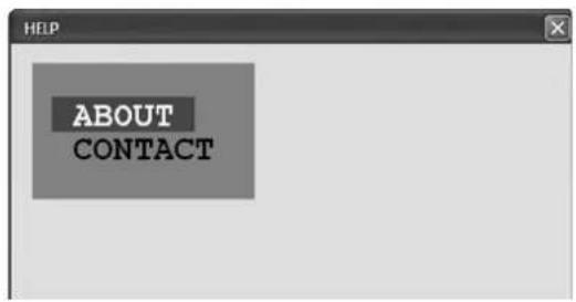
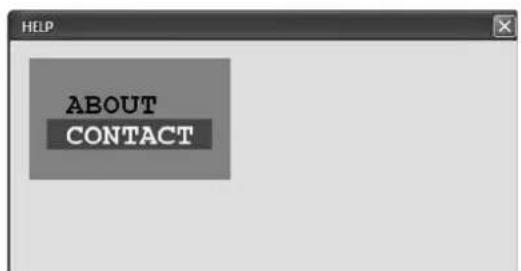
The last menu item, HELP, provides the following information:
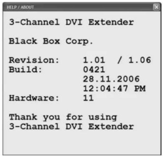
ABOUT information about the fi rmware
CONTACT information about the manufacturer of your 3-Channel DVI Extender
The ABOUT window in the HELP menu shows the current hardware and software revisions of your 3-Channel DVI Extender. Please see page 27 for information on updates.
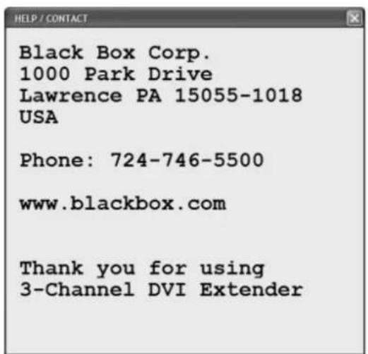
The CONTACT window shows all necessary contact data of BLACK BOX Corp.
Please visit our website.
For a fi rmware update, you need:
- one computer running the Windows operating system with one available RS232 COM port
- your 3-Channel DVI Extender TX transmitter unit
- update CD with the updateEn.exe file
• one serial cable (included in deliverables)
Please proceed as follows:
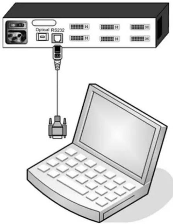
- Use the serial cable to connect the COM port of your computer to the RJ45 port (RS232) on your 3-Channel DVI Extender TX.
- Switch on the power supply of your 3-Channel DVI Extender TX.
- Insert the update CD. Open the updateEn.exe program.
- Confi gure the selected interface to your computer under COM port (default = COM 1).
- Please enter the drive and the path of the current fi rmware in Update File, or select the fi le using the "Browse...." button.
- Start the upgrade process by clicking on "Update".
- The LEDs will flash for during the entire upgrading process.
The update has been completed when the LEDs light up permanently again.
- Your 3-Channel DVI Extender TX will be ready for use after a power reset.
You can see the latest fi rmware status under HELP / ABOUT / Revision, as described on page 26.
TECHNICAL SPECIFICATIONS
Devices:
3-Channel DVI Extender 3 x DVI-I input ports (analog + digital)
transmitter: 3 x DVI-I output ports (analog output signal
only with analog input signal)
1 x MTP®/MPO 12-fiber fiberoptic output cable
1 x RJ45 for RS232 serial configuration cable
4 x LED
3-Channel DVI Extender 3 x DVI-D output ports (digital)
receiver: 1 x MTP®/MPO 12-fold fi beroptic input cable
4 x LED
Transmission medium: Fiberoptic patch cable
MTP®/MPO with 12-fold multimode fiber
G50/125
μm uncrossed female / female
(please indicate required custom length!)
Transmission rate: 3 x 165 MHz
Transmission distance: 62.5 μm: max. 300 meters
50
μm: max. 400 meters
Maximum resolution: 1920 x 1200 @ 60 Hz (digital)
1600 x 1200 @ 60 Hz (analog)
Power supply: 100 – 240 V AC - power input: 8 VA
per transmitter and receiver
Casing:
Powder-coated
steel
Dimensions (WxDxH): 219 x 170 x 43 mm
Color black RAL 9005
ACCESSORIES
Fiberoptic cable
BLACK BOX will supply custom MTP®/MPO fiberoptic cables precut to your desired length, up to a maximum distance of 400 meters.
Please note that these cables are prefabricated.
Please notify BLACK BOX of the precise length in meters!
Plug connector system: MTP®/MPO 12-fold multimode uncrossed female / female.
Extension box Order at request
If a video output device is more than five meters away from your 3-Channel DVI Extender RX receiver unit, you will need an extension box to amplify the signals.
If you experience poor signal transmission, please also check the quality of the used video cables, your video resolution settings and the quality of the video sources and output devices connected!
Maintenance and Repair
If the 3-Channel DVI Extender is malfunctioning, do not attempt to alter or repair the unit. It contains no user-serviceable parts.
Contact BLACK BOX at 724-746-5500 or see page 32 for technical support in Europe.
Before you do, make a record of the history of the problem. We will be able to provide more efficient and accurate assistance if you have a complete description, including:
- the nature and duration of the problem.
- when the problem occurs.
- the components involved in the problem.
- any particular application that, when used, appears to create the problem or make it worse.
Shipping and Packaging
If you need to transport or ship your 3-Channel DVI Extender:
- Package it carefully. We recommend that you use the original container.
- If you are shipping the 3-Channel DVI Extender for repair, make sure you include everything that came in the original package. Before you ship, contact Black Box to get a Return Authorization (RA) number.
Send your 3-Channel DVI Extender to:
Black Box Corporation
Attn: RA #
1000 Park Drive
Lawrence, PA 15055-1018
TECHNICAL SUPPORT
Worldwide contact information for technical support:
Country Web Site / Email Phone Fax
US www.blackbox.com 724-746-5500 724-746-0746 info@blackbox.com
Austria www.black-box.at +43 1 256 98 56 +43 1 256 98 56 support@black-box.at
Belgium www.blackbox.be +32 2 725 85 50 +32 2 725 92 12 support.nederlands@blackbox.be support.french@blackbox.be support.english@blackbox.be
Denmark www.blackbox.dk +45 56 63 30 10 +45 56 65 08 05 blackbox@blackbox.dk
Finland www.blackbox.fi +358 201 888 800 +358 201 888 808 tuki@blackbox.fi
France www.blackbox.fr +33 820 07 09 11 +33 820 05 07 09 tech@blackbox.fr
Germany www.black-box.de +49 811 5541 110 +49 811 5541 499 techsupp@black-box.de
Ireland www.blackbox.co.uk +353 1 662 2466 +353 1 662 2477 techhelp@blackbox.co.uk
Italy www.blackbox.it +39 02 27 404 700 +39 02 27 400 219 supporto.tecnico@blackbox.it
Netherlands www.blackbox.nl +31 30 241 7799 +31 30 241 4746 techsupport@blackbox.nl
Norway www.blackboxnorge.no +47 55 300 710 +47 55 300 701 support@blackboxnorge.no_
Spain www.blackbox.es +34 916 590 732 +34 916 239 784 tecnico@blackbox.es
Sweden www.blackboxab.se +46 08 44 55 890 +46 08 38 04 30 support@blackboxab.se
Switzerland www.black-box.ch +41 55 451 70 71 +41 55 451 70 75 support@black-box.ch
UK www.blackbox.co.uk +44 118 965 6000 +44 118 965 6001 techhelp@blackbox.co.uk
INSTRUCCIONES DE SEGURIDAD (Normas Oficiales Mexicanas Electrical Safety Statement)
DECLARATION OF CONFORMITY and FCC DECLARATION
DECLARATION OF CONFORMITY
EUROPEAN UNION DECLARATION OF CONFORMITY
This equipment complies with the requirements of the European EMC Directive 89/336/EEC.

FCC DECLARATION
FEDERAL COMMUNICATIONS COMMISSION AND INDUSTRY CANADA RADIO FREQUENCY INTERFERENCE STATEMENTS
This equipment generates, uses, and can radiate radio-frequency energy, and if not installed and used properly, that is, in strict accordance with the manufacturer's instructions, may cause interference to radio communication. It has been tested and found to comply with the limits for a Class A computing device in accordance with the specifications in Subpart B of Part 15 of FCC rules, which are designed to provide reasonable protection against such interference when the equipment is operated in a commercial environment. Operation of this equipment in a residential area is likely to cause interference, in which case the user at his own expense will be required to take whatever measures may be necessary to correct the interference.
Changes or modifications not expressly approved by the party responsible for compliance could void the user's authority to operate the equipment.
This digital apparatus does not exceed the Class A limits for radio noise emission from digital apparatus set out in the Radio Interference Regulation of Industry Canada.
- 3-Channel DVI Extender
- Installation and Operation Manual
- BLACK BOX
- Excellent image quality, even at high resolutions!
- INTRODUCTION
- TABLE OF CONTENTS
- SAFETY GUIDELINES
- CAUTION: LASER
- DEVICE CONNECTIONS
- EXPLANATION OF CONNECTIONS
- HARDWARE INSTALLATION
- Safety information:
- Installation steps:
- Please note:
- DEVICE CONFIGURATION PROGRAM INSTALLATION
- SETTINGS
- Communication settings:
- Log parameters:
- Start configuration:
- CONFIGURATION
- PROGRAM START
- NAVIGATION
- BRIEF CONFIGURATION OVERVIEW
- Main window Sub-window Possible settings
- VIDEO INPUT
- IMPORTANT NOTE:
- BRIGHTNESS
- CONTRAST
- HORIZONTAL POSITION
- VERTICAL POSITION
- SCREEN WIDTH
- PHASE
- SYSTEM
- FACTORY RESET
- EDID
- EDID INTERNAL and DEFAULT
- NOTE:
- EDID EXTERNAL IMPORTANT!
- HELP
- TECHNICAL SPECIFICATIONS
- ACCESSORIES
- Fiberoptic cable
- Extension box Order at request
- Maintenance and Repair
- TECHNICAL SUPPORT
- Worldwide contact information for technical support:
- Country Web Site / Email Phone Fax
- INSTRUCCIONES DE SEGURIDAD (Normas Oficiales Mexicanas Electrical Safety Statement)
- DECLARATION OF CONFORMITY and FCC DECLARATION
- DECLARATION OF CONFORMITY
- EUROPEAN UNION DECLARATION OF CONFORMITY
- FCC DECLARATION
- FEDERAL COMMUNICATIONS COMMISSION AND INDUSTRY CANADA RADIO FREQUENCY INTERFERENCE STATEMENTS
Brand : Black Box
Model : AC1070A
Category : AV Extender