
Rolleramic 240 - Projection screen Draper - Free user manual and instructions
Find the device manual for free Rolleramic 240 Draper in PDF.


| Product Type | Motorized projection screen |
| Brand | Draper |
| Model | Rolleramic 240 |
| Screen Material | Matte white vinyl |
| Diagonal Size | 100-200 inches (customizable) |
| Aspect Ratio | 16:9 (standard) |
| Motor Type | Quiet, tubular motor |
| Power Supply | 120V AC, 60Hz |
| Control Options | Wall switch, remote control, IR/RS232 |
| Installation | Ceiling or wall mount |
| Weight | Approximately 15-30 lbs (varies by size) |
| Operating Temperature | 50-95°F (10-35°C) |
| Safety Certifications | UL listed, CE compliant |
| Maintenance | Wipe with soft dry cloth; avoid solvents |
| Repairability | Motor and control module replaceable by technician |
Frequently Asked Questions - Rolleramic 240 Draper
User questions about Rolleramic 240 Draper
0 question about this device. Answer the ones you know or ask your own.
Ask a new question about this device
Download the instructions for your Projection screen in PDF format for free! Find your manual Rolleramic 240 - Draper and take your electronic device back in hand. On this page are published all the documents necessary for the use of your device. Rolleramic 240 by Draper.
USER MANUAL Rolleramic 240 Draper
Installation/Operating Instructions
Rolleramic Electric Projection Screen by Draper
Caution
① Read instructions through completely before proceeding.
② Follow instructions carefully. Installation contrary to instructions invalidates warranty.
③ Do not lift case in center. Lift the ends simultaneously to avoid damage to case and surface.
④ Entire bottom of screen case should be unobstructed to permit access to bottom panels for making electrical connections or servicing. Motor end bracket must be located 1"-6" to right of access door. Idler end bracket must be located 6"-12" from right end of case. Failure to mount brackets as directed could cause the case to bow and result in damage to screen.
⑤ Keep case level when lifting and mounting. Screen should be installed level (using a carpenter's level).
⑥ Nothing should be fastened to screen dowel or viewing surface.
⑦ Do not touch screen while in motion.
⑧ Operating switch (es) packed separately in screen carton. Do not discard with packing material.
⑨ Screen operates on 110-120V, 60 hz., .78 amp draw (1.35 with heavy duty motor).
NOTE: Screen has been thoroughly inspected and tested at factory and found to be operating properly prior to shipment.
These instructions are meant as a guide only. They do not imply any responsibility on the part of Draper, Inc. for improper installation or faulty workmanship at the jobsite.
Hanging Screen
General:
When locating viewing surface and checking clearance for screen operation, remember surface is not centered in screen case: see dimensional drawings on reverse. All installations should observe these important criteria:
① Screen should be positively and securely supported so that vibration or even abusive pulling on viewing surface will not weaken installation.
② Installer must insure that fasteners used are of adequate strength and suitable for the mounting surface.
③ Entire bottom of case must be readily accessible after installation is complete. Be sure the access door opens freely for adjustments and service.
④ Installer should make sure mounting brackets are flush with the sides of the case to provide stability when hanging screen. Keep case level when lifting and mounting.
③ Screens through 14' wide have 2 mounting brackets; wider screens have 3. Brackets should be located along case to line up with supporting beams or studding. Motor end bracket must be located 1"-6" to right of access door. Idler end bracket must be located 6"-12" from right end of case. Failure to mount brackets as directed could cause the case to bow and result in damage to screen.
Please Note: Mount the case using the two end brackets first. If a center bracket is provided, mount it last. The center bracket is designed to prevent sagging of the case, and must be mounted so that it is level with the others and does not force the screen case up.
⑥ Make sure the top of the screen case's bottom board at no point touches the roller/viewing surface.
⑦ Do not use screen case to support adjacent sections of ceiling.
⑧ If trim pieces must be attached to case, do not permit screws to pro trude through 34 " wall of case. Do not attach trim with nails.
⑨ If case is painted, viewing surface slot must be shielded to protect viewing surface from paint splatters and overspray.
⑩ Do not seal unit in ceiling until electrical connections have been made and screen has been operated successfully. Screen must always be installed level so that fabric will not roll incorrectly or wrinkle.
Please Note: The Rolleramic is not available with the TorkStar Utility Line Set.
Wall Installation—
Brackets should fasten to studding or other structural supports within wall.
Suspended Installation—
Chains should be attached to solid beams or rafters above screen. If possible, screen mounting brackets should be positioned so chains hang vertically. Turnbuckles should be connected between chains and mounting brackets. After screen has been suspended, turnbuckles should be adjusted so that screen hangs level.
Recessed Installation—
Recess should be constructed to fit screen case with brackets (see "Case Dimensions" on back page). Design recess so that entire bottom of screen case is unobstructed to permit access to bottom panel, screen roller and surface for servicing if required.

411 S. Pearl St., Spiceland, IN 47385 USA ■ 765-987-7999
www.draperinc.com ■ fax 765-987-7142
Copyright © 2013 Draper Inc. Form Rolleramic_Inst13 Printed in U.S.A.
Electrical Connections
Screen operates on 110-120V, 60 Hz. AC, .78 amp draw (1.35 with heavy duty motor).
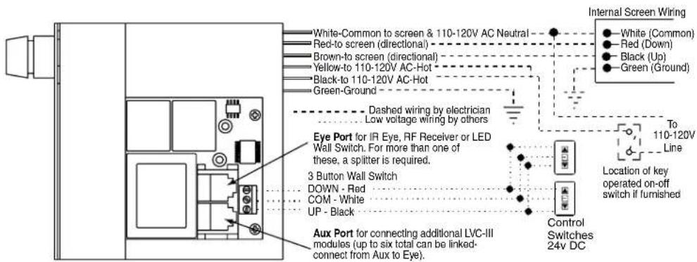
Screens are shipped with internal wiring complete, with all switches (fully boxed) and a wiring diagram. Wire connecting screen to switch (or switches) and switch to power supply should be supplied by installer. Wires should be connected following the wiring diagram provided, and all wiring should comply with local and national electrical codes.
All operating switches should be "Off" before power is connected.
Operation
Remove all packing before attempting to operate screen. When screen is first operated, be cautious! Cycle unit down and up several times to confirm satisfactory operation.
110-120V Single Station Control — 3-position up-off-down switch permits operation to be stopped at any point. Factory adjusted limit switches automatically stop screen when fully down or fully up.
110-120V Multiple Station Control — Switches are similar in appearance to 110-120V Single Station Control. Screen stops when switch is released and may be restarted in either direction. Factory adjusted limit switches stop screen automatically when fully down or fully up.
24V Control — Three-button up-stop-down switches stop at any point desired, operate in any sequence. Factory adjusted limit switches automatically stop screen when fully down or fully up.
Key Operated Switching — Two kinds of key-operated switches are optionally available with this unit.
① The key-operated power supply switch controls power to the screen and switches. When it is "off", the switches will not operate screen. Key may be removed from the switch in either "on" or "off" position.
② A three-position key switch permits the screen to be operated directly by key. In this case, the screen's operator must always have a key.
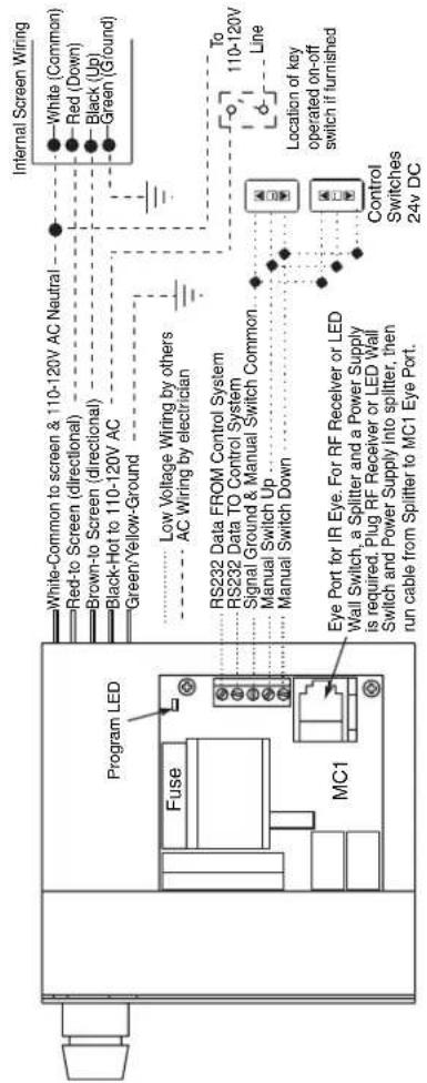
RS232/Ethernet—Serial communication and network communication optionally available with wall switches, RF or IR remote.
Adjustments
Please Note: Screen limits are factory set for optimum performance of the screen. A procedure is outlined below for minor tweaks, but any adjustment of these limits may negatively affect the flatness of the screen surface and could also void the warranty. Please check with Draper prior to resetting screen limits.
⚠️CAUTION: Always be prepared to shut screen off manually when new adjustment is being tested. Screen may be severely damaged if viewing surface is allowed to run too far up or too far down.
⚠️CAUTION: Be sure all switches are in “off” position before adjusting limit switches.
△CAUTION: Do not loosen coupling setscrews from the roller shaft, or the screen surface will rapidly unroll and fall. If setscrew must be loosened actions should be taken to prevent the roller from turning.
Adjusting "fully up" position — "Up" limit switch is located on right side of limit switch assembly, immediately behind access door to case. Right hand, hex head machine screw contacts limit switch button to shut screen off. Turning this machine screw clockwise will allow surface to run farther up into case. Turning it counterclockwise will cause screen to stop sooner, farther out of the case.
Adjusting "fully down" position — "Down" limit switch is located on left side of limit switch assembly, immediately behind access door to case. Left hand, hex head machine screw contacts limit switch button to shut screen off. Turning this machine screw clockwise will allow surface to run farther down before stopping. Turning it counterclockwise will cause screen to stop in a less extended position. At no time should fabric be unrolled far enough to expose any part of screen roller. Make all adjustments in small increments, and be sure nut on machine screw is tight against steel limit switch support before closing access door.
Universal Mounting Bracket
may be suspended from above,
or mounted to wall. Each bracket
consists of a front and back piece
bolted together. 2 required and
supplied on screens up to 14' wide.
3 required and supplied on larger screens.
Conduit connection on left end of case.
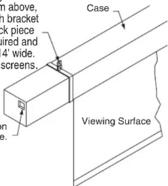
Motor end bracket must be located 1"-6" to right of access door. Idler end bracket must be located 6"-12" from right end of case. Failure to mount brackets as directed could cause the case to bow and result in damage to screen.
If you encounter any difficulties installing or servicing your Rolleramic screen, call your dealer or Draper, Inc., Spiceland, Indiana, (765) 987-7999, or fax (765) 987-7142.
Rolleramic by Draper
Case Dimensions
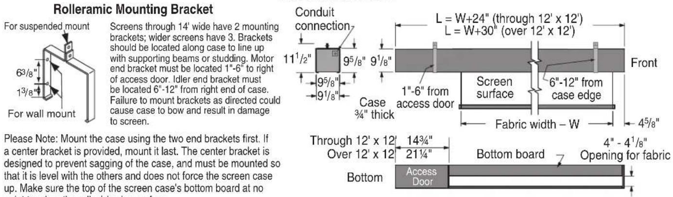
Rolleramic Wiring Diagrams
Please Note: Do not wire motors in parallel.
Single Station Control
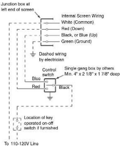
Rolleramics over 12' x 12' have a blue wire lead instead of a black wire lead coming from the motor.
Multiple Station Control
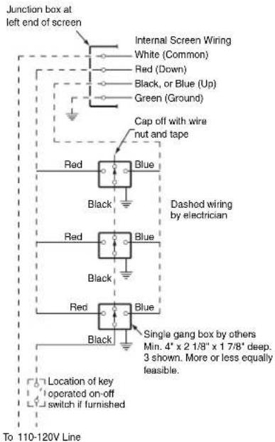
Low Voltage & Wireless Control
Two-Way Serial Communication (RS232) with MC1
See separate Serial Communication-RS232 Instruction sheet for enabling RS232 with the MC1.
Brand : Draper
Model : Rolleramic 240
Category : Projection screen