
Access FIT E - Projection screen Draper - Free user manual and instructions
Find the device manual for free Access FIT E Draper in PDF.


| Product Type | Electric Projection Screen |
| Model | Access FIT E |
| Brand | Draper |
| Voltage | 220V AC |
| Frequency | 50 Hz |
| Current Draw | 1.1 A |
| Duty Cycle | 28 seconds ON / 4 minutes OFF |
| Motor Type | 220V Standard or Quiet Motor with internal Low Voltage Controller |
| Control Options | Single Station, Multiple Station, Low Voltage, Video Interface, Key Operated, RS232/Ethernet, RF/IR Remote |
| Mounting | Ceiling mount with brackets; hoisting brackets included |
| Case Dimensions (approx) | Length: varies by size; width/depth: standard case dimensions |
| Minimum Ceiling Cutout | Subtract 38 mm from case length and width |
| Viewing Surface | Centered in case length |
| Tab-Tensioning | Factory-set; field adjustable |
| Limit Adjustments | Factory set; minor tweaks possible via limit screws or internal LVC switch |
| Environmental Rating | Suitable for environmental air space (per NEC and CEC) |
| Warranty | Invalidated if installation contrary to instructions |
| Accessories Included | Mounting brackets, operating switch(es), bottom access panel, hardware |
| User Manual Pages | 4 |
Frequently Asked Questions - Access FIT E Draper
User questions about Access FIT E Draper
0 question about this device. Answer the ones you know or ask your own.
Ask a new question about this device
Download the instructions for your Projection screen in PDF format for free! Find your manual Access FIT E - Draper and take your electronic device back in hand. On this page are published all the documents necessary for the use of your device. Access FIT E by Draper.
USER MANUAL Access FIT E Draper
Installation/Operating Instructions
Access Fit 220V Electric Projection Screen by Draper
US Patent Nos.
6,137,629; 6,421,175;
6,532,109; 6,816,308;
7,559,707
Caution
① Read instructions through completely before proceeding; keep them for future reference. Follow instructions carefully. Installation contrary to instructions invalidates warranty. Care in mounting and correct operation will mean long and satisfactory service from your Draper screen.
② Before removing screen from crate, check for damage and to make sure all parts are included.
③ Allow enough access to remove front cover should fabric become damaged or should other service be required.
④ Screen should be installed level (using a carpenter's level).
⑤ Nothing should be fastened to screen dowel or viewing surface.
⑥ Operating switch(es) is packed separately in screen carton. Do not discard with packing material.
⑦ Screen operates on 220V, 50 Hz. 1.1 amp current draw.
NOTE: Screen has been thoroughly inspected and tested at factory and found to be operating properly prior to shipment.
These instructions are meant as a guide only. They do not imply any responsibility on the part of the manufacturer for improper installation or faulty workmanship at the jobsite.
Hanging Screen
When locating viewing surface and checking clearance for screen operation, remember surface is centered in the length of the case. Regardless of mounting method used, the following points apply:
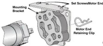
① Mounting brackets are shipped attached to the case. Engage each bracket with top of housing as shown below and tighten set screws.
② Screen should be positively and securely supported so that vibration or even abusive pulling on viewing surface will not weaken installation.
Please Note: A Hoisting Bracket is included on each end of the case to aid in overhead installation of the Access Fit case.
③ Installer must insure that fasteners used are of adequate strength and suitable for the mounting surface chosen. Supporting hardware (chains, cables, 9.5mm rods, etc.) must be essentially vertical.


(additional set of brackets required but not included)
^1 With typical installation, brackets may be angled to meet installation requirements.
④ Entire bottom of case must be readily accessible after installation is complete.
⑤ Front, back and top of case must be straight— not forced to warp or bow.
⑥ If case is painted on location, removal of roller/fabric assembly is recommended prior to painting. If not removed, slot on bottom of case should be shielded to protect viewing surface from paint splatters/overspray.
⑦ Do not seal unit in ceiling until electrical connections have been made and screen has been operated successfully.
Suitable for use in environmental air space in accordance with Section 300-22(c) of the National Electrical Code, and Sections 2-128, 12-010(3) and 12-100 of the Canadian Electrical Code, Part 1, CSA C22.1.

411 S. Pearl St., Spiceland, IN 47385 USA ■ 765-987-7999
www.draperinc.com ■ fax 765-987-7142
Copyright © 2016 Draper Inc. Form AccessFit220V_Inst16 Printed in U.S.A
Electrical Connections
Screen operates on 220V, 50 Hz., 1.1 amp current draw.
Duty Cycle: ON 28 seconds /OFF 4 minutes.
Junction box is located just above the bottom access panel at left end of screen (standard, right end may be specified).
Remove the bottom access panel for access to the junction box cover. (See Bottom Access Panel Removal instructions below). Remove two (2) hex head screws that secure the cover to the junction box to expose the red, black, and white pigtail leads and the green ground wire per wiring diagram on page 4. If optional low voltage control is specified and factory installed, please refer to wiring diagrams on page 4.
Screen is shipped with internal wiring complete and control switch(es) fully boxed. Wire to connect screen to switch(es) and switch(es) to power supply should be furnished by installer. Connections should be made in accordance with attached wiring diagram, and wiring should comply with national and local electrical codes.
All operating switches should be "off" before power is connected.
Bottom Access Panel Installation/Removal
Bottom access panel is secured to the screen housing by two screws (one on each end), and is held in the closed position by engagement brackets with ball detents that snap into case support brackets.

To remove the Access Panel:
① Remove screws from both ends of screen housing (Fig. 4).
② Pull down on the access panel until the ball detents on the engagement bracket have disengaged from the support bracket.
③ Repeat Step ② for all brackets along the length of the screen housing.
④ The access panel will be free to pivot downward. It will remain attached to the lower inside edge of the screen housing by several steel hinges.

Caution: For larger sizes Step ⑤ requires two people to perform safely.
⑤ Press up on access panel and pull toward the front of the screen housing to disengage hinges and remove access panel.
To Remove/Install Support Brackets:

If you encounter any difficulties installing or servicing your Access Fit screen, call your dealer or Draper, Inc., in Spiceland, Indiana, 765/987-7999 or fax 765/987-7142.
Access Fit 220V Instructions by Draper page 2 of 4
Motorized Roller/Fabric Installation
Please note: When ordering a motor with internal Low Voltage Controller,
if the case ships separate from the "guts," the case includes the 2.36m cable and special low voltage switch.
① The bottom access panel must be removed first. (Pg 1, Fig. 4).
② The motor end mounting bracket has a metal bracket with snap ring for accepting motor head. Back out the two set screws in bracket until they are flush with top side of bracket.
③ To engage the motor end bracket flange above the two channels in the top of the screen housing, rotate the bracket approximately 45^ counterclockwise to allow the top surface of the motor bracket to rest flat against the top inside of the housing.
④ Rotating the bracket clockwise until it is engaged with the channels, slide it along the length of the housing against the electrical junction box.
⑤ Engage idler end bracket (rectangular mounting pad) in the same manner as motor end bracket and slide it toward the opposite end of the screen housing. Do not tighten set screws on this bracket until the roller/fabric assembly is installed, and centered in case.
Note: Step 6 requires two people to perform safely.
⑥ Locate the black washer and retaining clips attached to the instruction sheet.
Raise the roller/fabric assembly up into the screen housing and engage the
head of the motor completely into the motor mounting
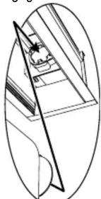
bracket, making sure the limit switch adjusting knobs are visible from the bottom of the screen housing (see fig. 8). If snap ring is provided, make sure the snap ring engages with the motor. If retaining clip is provided instead, install to lock motor end in place.
⑦ While supporting the idler end of the roller, slide the idler end mounting bracket toward the roller. Insert the roller pin into the nylon bushing on the idler end mounting bracket.
⑧ The roller idler pin needs to go through the idler bracket far enough to allow the washer and retaining clip to be reinstalled on the pin.
CAUTION: Failure to replace the washer and retaining clip could result in the separation of the roller from the brackets.
⑨ The roller/fabric assembly and roller brackets may need to be slid left or right in the mounting channel of case to center fabric within screen case.
⑩ Securely tighten the set screws on roller mounting brackets.
⑪ Connect the electrical plug from the motor to the mating socket on the junction box.
⑫ Reinstall the bottom access panel as previously described.
Motorized Roller/Fabric Removal
Reverse the instructions above “Motorized Roller/Fabric Installation” for removal of the unit.
Operation
When screen is first operated, be cautious! Cycle unit down and up several times to confirm satisfactory operation.
220V SINGLE STATION CONTROL—3-position UP-OFF-DOWN switch permits operation to be stopped at any point. Factory adjusted limit switches automatically stop screen when fully down or fully up.
220V MULTIPLE STATION CONTROL—Switches are similar in appearance to 110-120V Single Station Control. Screen stops when switch is released and may be restarted in either direction. Factory adjusted limit switches stop screen automatically when fully up or fully down.
24V CONTROL—Three-button UP-STOP-DOWN switches stop at any point desired, operate in any sequence. Factory adjusted limit switches automatically stop screen when fully up or fully down. Installer should incorporate an all-pole disconnect in the fixed wiring available with RF or IR remote.
220V & 12V VIDEO INTERFACE CONTROL—Allows screen to be controlled by trigger signal—when the signal comes on, the screen descends automatically. Two versions: Model VIC115 integrates screen operation with a Draper video projector lift or a video projector or tuner with a 220V switched outlet. Model VIC12 interfaces with a 12V switched outlet. Both available with an override switch (VIC–OS), permitting independent operation. VIC–OS not available with factory installed VIC115 & VIC12.
KEY OPERATED SWITCHING—Two kinds of key-operated switches are optionally available with this unit. ① The key-operated power supply switch controls power to the screen and switches. When it is “off”, the switches will not operate screen. Key may be removed from the switch in either “on” or “off” position.
② A three-position key switch permits the screen to be operated directly by key. In this case, the screen's operator must always have a key.
RS232/ETHERNET—Serial communication and network communication optionally available with wall switches, RF or IR remote.
Tab-Tension Adjustment Procedure for Access Fit/Series V
Draper's Tab-Tensioning System is factory-set, and under normal circumstances will not require field adjustment. If, however, you notice wrinkles, waves or other indications that the tensioning cables need to be adjusted, follow the procedure below.
① Determine which side requires adjustment.
② Secure dowel with one hand.
③ Using Phillips-head screwdriver, depress spring-loaded adjustment screw and slowly turn CLOCKWISE TO INCREASE tension, or
COUNTER-CLOCKWISE TO RELEASE tension. The screw adjusts in 60° turn increments. Adjust only one increment (60°) at a time.

natural_image
Pure technical line drawing of a mechanical assembly without any text, numbers, or symbolsFigure ⑧
Fig. 4). Figure ⑥

④ If problem is not corrected, leave screen in position for 24 hours to allow surface material to stretch into position.
⑤ If problem still is not corrected, repeat steps 2 and 3.
Limit Adjustments (Standard/Quiet Motors)
Please Note: Screen limits are factory set for optimum performance of the screen. A procedure is outlined below for minor tweaks, but any adjustment of these limits may negatively affect the flatness of the screen surface and could also void the warranty. Please check with Draper prior to resetting screen limits.
⚠️CAUTION: Always be prepared to shut screen off manually when new adjustment is being tested. Screen may be severely damaged if viewing surface is allowed to run too far up or too far down.
⚠️CAUTION: Be sure all switches are in “off” position before adjusting limit switches. The motor limit screws are normally located on the audience left of screen roller.
**Please Note: If the Access Fit E/V is "Right Hand Motor" or "Waterfall", the WHITE/DOWN (I) and YELLOW/UP (II) limit screws are reversed. See graphic below.
"Down" Limit Adjustment
To Reduce Screen Drop
① Raise screen surface about 1' above desired setting and turn off.
② Turn the WHITE/DOWN (I) limit screw clockwise (three screw turns = 12 roller revolution).
③ Test by running screen down and repeat steps 1 and 2 until desired position is reached.
To Increase Screen Drop
① Run screen to the down limit.
② With the down switch on, turn the WHITE/DOWN (I) limit screw counterclockwise (3 turns of screw equals 12 roller revolution) to increase drop.
③ Test by running screen up about 1' and back down to new down limit.
④ Repeat steps 2 and 3 until desired position is reached.
"Up" Limit Adjustment
Screen is Running Too Far Up
① Lower screen surface about 1' below desired setting and turn off.
② Turn the YELLOW/UP (II) limit screw clockwise (3 screw turns = 12 roller revolution).
③ Test by running screen up.
④ Repeat steps 1 through 3 until desired position is reached.
Screen Needs to Run Up More
① Run screen down about 1' and turn off.
② With the up switch on, turn the YELLOW/UP (II) limit screw counterclockwise (3 turns of screw equals 12 roller revolution).
③ Repeat steps 1 and 2 until desired position is reached.
CAUTION: Do NOT allow the dowel to wrap up over the roller when the screen is running up! This could damage the screen.
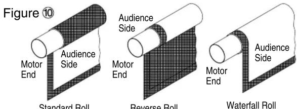
Standard/Reverse Roll
Left hand motor
White Socket—Down
Yellow Socket—Up
Right hand motor
White Socket—Up
Yellow Socket—Down
Waterfall Roll
Left hand motor
White Socket—Up
Yellow Socket—Down
Right hand motor
White Socket—Down
Yellow Socket—Up
Access Fit 220V Instructions by Draper page 3 of 4
Limit Adjustments (Low Voltage Motors with Internal Low Voltage Controller)
Please Note: Screen limits are factory set for optimum performance of the screen. A procedure is outlined below for minor tweaks, but any adjustment of these limits may negatively affect the flatness of the screen surface and could also void the warranty. Please check with Draper prior to resetting screen limits.
⚠️CAUTION: Always be prepared to shut screen off manually when new adjustment is being tested. Screen may be severely damaged if viewing surface is allowed to run too far up or too far down.
⚠️CAUTION: Be sure all switches are in “off” position before adjusting limit switches.

Figure ⑪
Please Note: 5V DC must be connected to be able to set limits using the wall switch.
| POSITION | FUNCTION |
| DOWN | Set LOWER limit |
| UP | Set UPPER limit |
| CENTER | Normal Operation |
Please note: When ordering a motor with internal Low Voltage Controller, if the case ships separate from the "guts," the case includes the 7.6m cable and special low voltage switch.
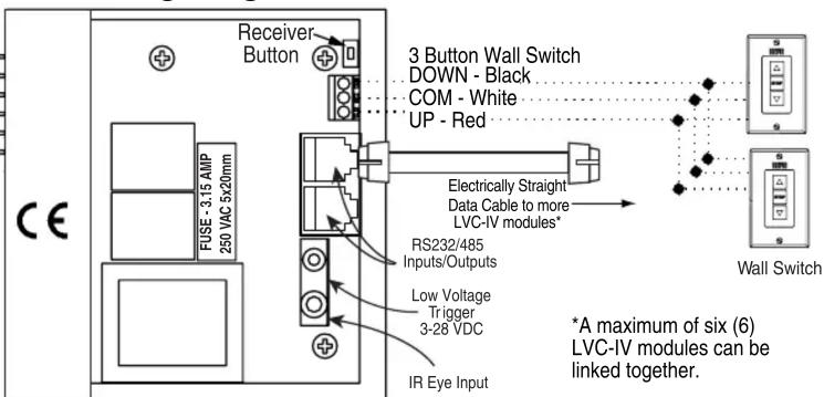
① Connect the ILT switch to the motor via the terminal blocks, or via the modular port using four conductor modular cable. When using modular cable, the cable connectors MUST NOT be crimped in reverse, as with standard telephone cable. (For a Dry Contacts Wiring Diagram, see page 4.)
② Set the slide switch to the lower position. Press and hold the DOWN button on the switch to move the viewing surface to the desired lower limit. If the screen moves in the opposite direction, release the DOWN button and press and hold down the STOP button for four seconds. This will reverse the operation of the UP and DOWN switches.
③ Move slider switch into center position. Wait a couple of seconds.
Please Note: If you move the slider switch from down to up in one motion it sets the two limits in the same position.
④ Set the slide switch to the higher position. Move the viewing surface to desired upper limit by pressing and holding the UP button on wall switch.
⑤ Return the slide switch to the center position to return to normal operation.
⑥ To set the viewing surface to an alternate format position, move the viewing surface to the desired position and press the STOP button. Press and hold the STOP button for at least three seconds to record the position.
Please Note: Pressing and releasing the UP button on the switch will move the screen to its upper limit. Pressing and releasing the DOWN button will move the screen to its lower limit.
While the motor is in motion, pressing the STOP button for less than two seconds will stop the viewing surface at its present position.
Once the motor is stopped, pressing the STOP button will move the viewing surface to its alternate format position.
Pressing and holding the STOP button, when the motor is at rest or in motion, for at least three seconds will record a new alternate format position.

For minimum ceiling cutout subtract 38mm from case length and width (measured from outer edge of flanges).
**There are several knock-outs in the screen housing to allow the Leveling Bracket to be adjusted laterally (up to 41cm in either direction)
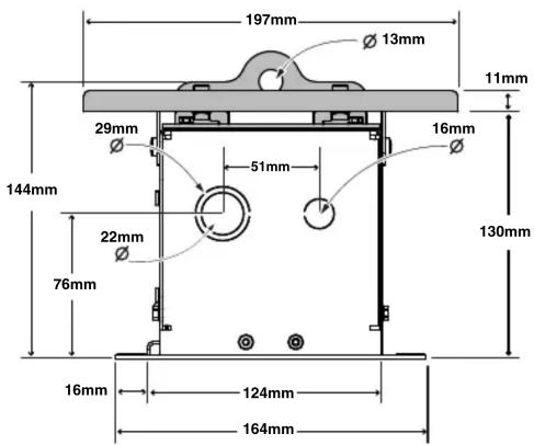
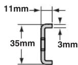
Mounting Bracket Dimensions


Access Fit 220V Instructions by Draper page 4 of 4 Wiring Diagrams—220V Standard Motor
Single Station Control/Einstationsbedienung/Commande monoposte
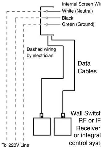
Wiring Diagrams—220V Motor and Quiet Motor with Internal Low Voltage Controller
flowchart
graph TD
    A["Internal Screen Wire"] --> B["White (Neutral)"]
    A --> C["Black"]
    A --> D["Green (Ground)"]
    B --> E["Dashed wiring by electrician"]
    C --> E
    D --> E
    E --> F["Data Cables"]
    F --> G["Wall Switch RF or IF Receiver or integral control syst"]
    G --> H["To 220V Line"]
*These wiring diagrams are for Access Fit screens with motor on audience left (standard), and fabric unrolling from the back of the roller (standard).
Data Cable Connection

Switch - to - Motor Connection
Dry Contacts

Internal LVC-IV - Single or Multiple Projection Screen Wiring Diagram
INTERNAL SCREEN WIRING


External LVC-IV - Single or Multiple Projection Screen Wiring Diagram
INTERNAL SCREEN WIRING

- Installation/Operating Instructions
- Access Fit 220V Electric Projection Screen by Draper
- Caution
- Hanging Screen
- Please Note: A Hoisting Bracket is included on each end of the case to aid in overhead installation of the Access Fit case.
- Electrical Connections
- Bottom Access Panel Installation/Removal
- To remove the Access Panel:
- Access Fit 220V Instructions by Draper page 2 of 4
- Motorized Roller/Fabric Installation
- Motorized Roller/Fabric Removal
- Operation
- Tab-Tension Adjustment Procedure for Access Fit/Series V
- Limit Adjustments (Standard/Quiet Motors)
- "Down" Limit Adjustment
- To Reduce Screen Drop
- To Increase Screen Drop
- "Up" Limit Adjustment
- Screen is Running Too Far Up
- Screen Needs to Run Up More
- Access Fit 220V Instructions by Draper page 3 of 4
- Limit Adjustments (Low Voltage Motors with Internal Low Voltage Controller)
- Access Fit 220V Instructions by Draper page 4 of 4 Wiring Diagrams—220V Standard Motor
Brand : Draper
Model : Access FIT E
Category : Projection screen