
PMX830I - Blender Pyle - Free user manual and instructions
Find the device manual for free PMX830I Pyle in PDF.


| Product Type | Countertop Blender |
| Brand | Pyle |
| Model | PMX830I |
| Power | 600 Watts |
| Capacity | 1.5 Liters (6 cups) |
| Speed Settings | 3 Speeds + Pulse Function |
| Jug Material | Plastic (BPA-Free) |
| Blade Material | Stainless Steel |
| Dimensions (W x D x H) | 7.5 x 7.5 x 15 inches |
| Weight | 4.2 lbs (1.9 kg) |
| Power Supply | 120V / 60Hz |
| Cord Length | 3 feet |
| Safety Feature | Auto Shut-Off / Thermal Protection |
| Cleaning | Hand wash recommended; removable blades for cleaning |
| Warranty | 1 Year Limited Warranty |
| Accessories Included | Measuring Cup |
Frequently Asked Questions - PMX830I Pyle
User questions about PMX830I Pyle
0 question about this device. Answer the ones you know or ask your own.
Ask a new question about this device
Download the instructions for your Blender in PDF format for free! Find your manual PMX830I - Pyle and take your electronic device back in hand. On this page are published all the documents necessary for the use of your device. PMX830I by Pyle.
USER MANUAL PMX830I Pyle
◆ 4/6/8 Channel balanced microphone and line inputs.
◆Treble, bass, reverb level control on each channel.
◆Support USB/SD memory card MP3 / WMA music format player.
◆Return, CD (TAPE) input.
◆Send, earphones, REC output.
◆5 band graphic Equalizer.
IMPORTANT SAFETY SYMBOLS


The symbol is used to indicate that some hazardous live terminals are involved within this apparatus, even under the normal operating conditions, which may be sufficient to constitute the risk of electric shock or death.

The symbol is used in the service documentation to indicate that specific component shall be replaced only by the component specified in that documentation for safety reasons.

Protected grounding terminals
Alternating current/voltage.
Hazardous live terminal.
ON: Denotes the apparatus is turned on.
OFF: Denotes the apparatus is turned off.
WARNING: Describes precautions that should be observed to prevent the danger of injury or death to the operator.
CAUTION: Describes precautions that should be observed to prevent danger of the apparatus.
IMPORTANT SAFETY INSTRUCTIONS
- Read these instructions.
- Keep these instructions.
- Heed all warning.
- Follow all instructions.
•Water& Moisture.
• Water & Moisture
This Unit should be protected from moisture and rain, can not be used near water, for example: near bathtubs, kitchen sinks or a swimming pools, etc.
- Heat
This unit should be located away from the heat source such as radiators, stoves or other appliances that produce heat.
- Ventilation
Do not block areas of ventilation opening. Failure to do could result in fire. Always install accordance with the manufacturer's instructions.
• Power Cord and Plug
Protect the power cord from being walked on or pinched particularly at plugs, especially receptacles, and the point where they exit from the apparatus. Do not defeat the safety purpose of the polarized or grounding-type plug. A polarized plug has two blades with one wider than the other. A grounding type plug has two blades and a third grounding prong. The wide blade or the third prong is provided for your safety. If the provided plug does not fit into your outlet, refer to electrician for replacement.
• Power Supply
The apparatus should be connected to the power supply only of the type as marked on the apparatus or described in the manual. Failure to do could result in damage to the product and possibly the user.
Unplug this apparatus during lightning storms or when unused for long periods of time.
- Fuse
To prevent the risk of fire and damaging the unit, please use only of the recommended fuse type as described in the manual. Before replacing the fuse, make sure the unit turned off and disconnected from the AC outlet.
• Electrical Connection
Improper electrical wiring may invalidate the product warranty.
- Cleaning
Clean only with a dry cloth. Do not use any solvents such as benzyl or alcohol.
•Servicing
Do not implement any servicing other than those means described in the manual.
Refer all servicing to qualified service personnel only. Only use accessories/attachments or parts recommended by the manufacturer.
- Warning
Please remember the high sound pressure do not only temporarily damage your sense of hearing, but can also cause permanent damage. Be careful to select a suitable volume.
CAUTION!
We should like to draw your attention to the fact that extreme volumes may damage your hearing and/or your headphones or loudspeakers. Turn the MAIN MIX control and phones control in the main section fully down before you switch on the unit. Always be careful to set appropriate volume levels.
1. CONTROL ELEMENTS AND CONNECTORS
1. FRONT PANEL
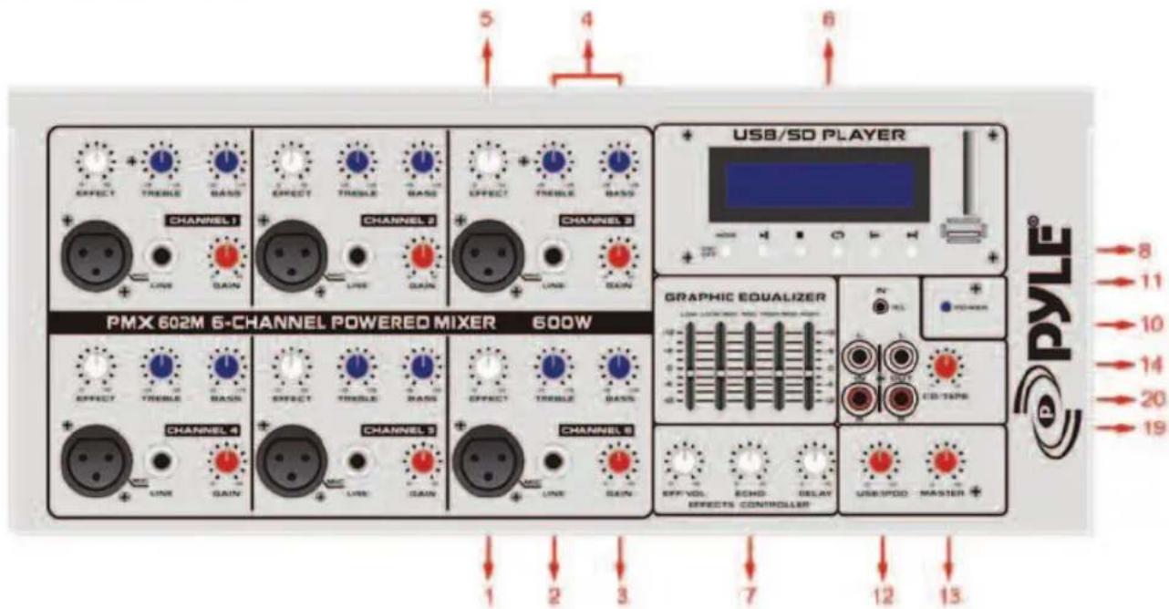
1) 3 Pin Low impedance Microphone input-This input is for balanced low Is always on and available, It has an input impedance of 1K ohm. The connector Is wired as: Pin 1+ shield Pin 3±negative (cold)
2)1/4 Line/High Impedance balanced input this may be used as either a high Impedance microphone input or a line level device such as tape players. CD Player Returns or radios. It will also allow connection from an electric guitar, Bass, or keyboard It is a 2—conductor input with an impedance of 10k ohms. Both the high and low impedance input may be used simultaneously.
3) Gain this is the volume control for each channel. It sends the Signal to the master mix buss. Typical operation is between 4 and 8, dependent the device(s) on that channel,
please remember that it acts like a pre amp, So if you are using a device that has a volume output control (i, e, :a tape or CD Player) you will need to do some level matching by adjusting the level controls on Each unit.
4) EQ Control This is to adjust the overall tone of the individual inputs. It is set at 60Hz/IOkHz. Since it is a cut or boost control, (+/-15dB) it will add or Diminish the sound quality.
5) EFFX Control this is a send control to the reverb bus. It controls the amount of Reverberation added to the input signals.
6) USB/SD player, this is a support USB/SD memory card MP3 / WMA music format player. By USB/SD to control the volume, typical operation is between 4 and 8.
7) Master EFFX This controls the level, of echo and time of internal reverberation added Back to the mix.
8) Master EQ This controls the overall amount of EQ frequencies (63 250 1K 4k 12kHz). This control allows +/-12dB of boost or cut.
9) This is a switch power switch, control of the machine on or off, will this machine start, you will see the blue LED indicator emit light.
10) Power LED Indicator
11)3.5mm input jack for use with personal music players
12) Volume control for USB/SD
Please do not connect microphones to the mixer (or the stage box or wall box) as long as the phantom power supply in switched on. Connect the micro-Phones before you switch on the power supply. IN addition, the monitor/PA loudspeakers should be muted before you activate the phantom power supply. After switching on, wait approx. One minute in order to allow system stabilization.
13) Master Volume This controls the overall volume level of the entire amplifier. Typical operation is between 4 and 8.
14) Tape Volume this controls the level, of the playback inputs (RCA jack on rear
Panel).

15) AC Cable this is a standard cable for use with standard voltages from A. C. Wall Outlets. It is grounded and should NEVER have the ground pin removed for any Reason.
16)Speaker output, each channel impedance is 8. Ohm
17) RETURN These 1/4 jack are for brining in a effects return effect or other
Line level source. the impedance is 10K ohms@-10dBv.
18) SEND Out—this is a 1/4 2-conductor line output. The impedance is 1k ohm @-10dB. It is used to connect the either additional power or as an additional Recording device. This line level signal is a mirror image of the mail outputs.
19) Tape play (L/R) These RCA jacks are for brining in a deck. CD play or other line Level source. The impedance is 10K ohm @-10dB.
20) Tape Record (L/R) These RCA jack are for hooking up a tape desk to record from The mixer. Both channels are summed into mono for compatibility. The signals are Taken pre-master section, meaning that they are without reverb or the master tone Section and does not include the tape in signal, the impedance is 1k ohm@-10dB.
2. INSTALLION
2. Main Connection
AC POWER
Connect the power supply to the 3-pin mains connector on the rear of the console. Use the AC adapter supplied to connect the console to the mains. The adapter complies with all applicable safety standards.

Please use only the power supply unit provided with the console.
Never connect the ME to the power supply unit while the latter is powered! First connect the console to the power supply unit, and then connect the power supply unit to the mains.
2. 2Audio connections
You will need a larger number of cables for the various connections to and from the console. Please see the illustrations shown below. Be sure to use only high-grade cable.
Please use commercial RCA cables to wire the 2—track inputs and outputs.
You can, of course, also connect unbalanced devices to the balanced input/outputs. Use either mono plugs, or ensure that ring and sleeve are bridged inside the stereo plug (or pins 1 & 3 in the case of XLR connectors).

Caution! Never use unbalanced XLR connectors (PIN I and 3 connected) on the MIC input connectors when using the phantom power supply.
Balanced use with XLR connectors

natural_image
Simple diagram of a beaker with three internal dots, no text or symbols presentInput
1=groud / shield
2=hot(+ve)
3=cold (-ve)

Output
For unbalanced use pin 1 and pin 3 have to be bridged
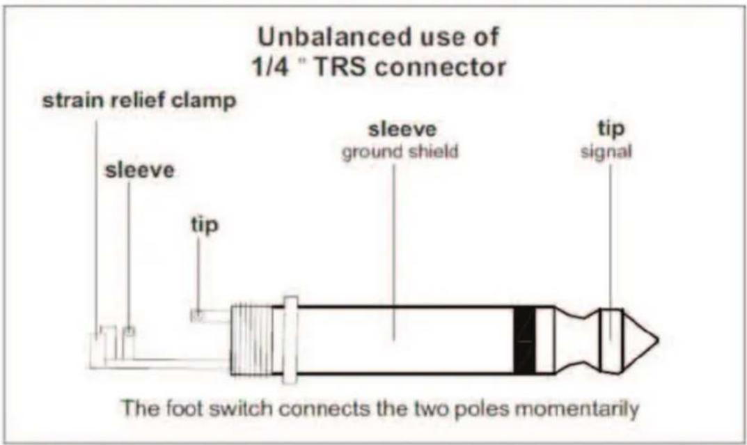
Fig. 2.3: 1/4 stereo plug

Fig. 2.4: Stereo plug for headphones connection

3. SPECIFICATIONS
Mono inputs
Microphone inputs (XENYX Mic Preamp)
Type
XLR, electronically balanced, discrete input circuit
Mic E. I. N. (20 Hz 20 kHz)
@ 0 Ωsource resistance
-134 dB / 135.7 dB A-weighted
@ 50 Ω source resistance
-131 dB / 133. 3 dB A-weighted
@ 150 Ω source resistance
-129 dB / 130.5 dB A-weighted
Frequency response
<10 Hz -150 kHz (-1 dB).
<10 Hz -200 kHz (-3 dB),
Gain range
+10 to +60 dB
Max. Input level
+12 dBu @ +10 dB gain
Impedance
approx. 2.6 kΩ balanced
Signal-to noise ratio
110dB / 112 dBA-weighted
(0 dBu In @ +22 dB gain)
Distortion (THD+ N)
0.005% / 0.004% A—weighted
Line input
Type
1/4" TRS connector, Electronically balanced
Impedance
approx. 20(2 balanced
10kΩ unbalanced
Gain range
-10 to +40 dB
Max. Input level
+22 dBu@ 0 dB Gain
Channel Equalization
Frequency: Hz
control range High:
@10K
±/-15dB Low:
@60K
±/-15dB
+/-15dB
Master 5-band graphic equalizer
| Frequency: Hz | control range |
| 60 | +/- 12dB |
| 250 | +/- 12dB |
| 1K | +/- 12dB |
| 4K | +/- 12dB |
| 12K | +/- 12dB |
Effects Loop
Effects send
Type 1/4" TS connector, unbalanced
Impedance approx. 1k ohm
Max. Output level -10dBv
Effects return
Type 1/4"TSconnector, unbalanced
Impedance approx. 10K ohm
Max. Output level -10dBv
Control room outputs
Type RCA, unbalanced
Impedance approx. 1k ohm
output level -10dBv
Headphones output
Type 1/4" TRS connector, Stereo
Max. Output level +19 dBu / 150Ω(+25 dBu)

you can connect two or a 8 Ohm speakers or a 4Ohm speakers, but did not allow connect two 4Ohm horns.
Protection Circuit
Power on Mute 2 seconds

- IMPORTANT SAFETY SYMBOLS
- IMPORTANT SAFETY INSTRUCTIONS
- • Water & Moisture
- - Heat
- - Ventilation
- • Power Cord and Plug
- • Power Supply
- - Fuse
- • Electrical Connection
- - Cleaning
- •Servicing
- - Warning
- CAUTION!
- CONTROL ELEMENTS AND CONNECTORS
- FRONT PANEL
- INSTALLION
- Main Connection
- AC POWER
- 2Audio connections
- SPECIFICATIONS
- Mono inputs
- Microphone inputs (XENYX Mic Preamp)
- Channel Equalization
- Effects Loop
- Control room outputs
- Headphones output
Brand : Pyle
Model : PMX830I
Category : Blender