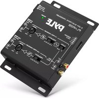
PLXR2B - Blender Pyle - Free user manual and instructions
Find the device manual for free PLXR2B Pyle in PDF.


| Product Type | Blender |
| Model | PLXR2B |
| Brand | Pyle |
| Power Consumption | 600 Watts |
| Jar Material | Plastic (BPA-free) |
| Blade Material | Stainless Steel |
| Capacity | 48 oz (1.4 L) |
| Number of Speeds | 2 speeds + Pulse |
| Control Type | Button |
| Dishwasher Safe Parts | Jar, lid, and blade assembly |
| Safety Feature | Locking lid with safety switch |
| Non-Slip Base | Yes |
| Weight | 4.5 lbs (2.04 kg) |
| Product Dimensions | 7.5 x 7.5 x 14.5 inches |
| Cord Length | 3.3 ft (1 m) |
| Voltage | 120 V / 60 Hz |
| Wattage | 600 W |
| Warranty | 1 Year Limited Warranty |
Frequently Asked Questions - PLXR2B Pyle
User questions about PLXR2B Pyle
0 question about this device. Answer the ones you know or ask your own.
Ask a new question about this device
Download the instructions for your Blender in PDF format for free! Find your manual PLXR2B - Pyle and take your electronic device back in hand. On this page are published all the documents necessary for the use of your device. PLXR2B by Pyle.
USER MANUAL PLXR2B Pyle
natural_image
Row of abstract geometric shapes including stars, circles, and triangles (no text or symbols)Independent High-Pass/Low-Pass
Output Level Controls
USER GUIDE
Specifications
Features:
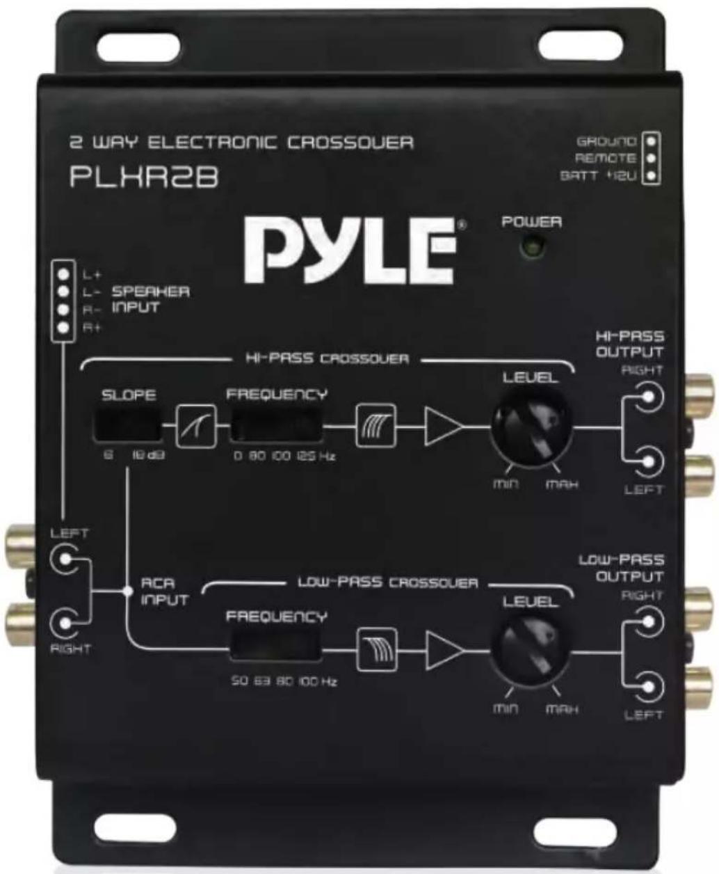
• 2-Way Electronic Crossover
- Compact Size
• High/Low Impedance Input
- Independent High-Pass/Low-Pass Output Level Controls
• Special and Better Crossover Slope Design
• 4-Channel RCA Outputs
• 2 Channel RCA Inputs
• Power on LED Indicator
What's in the Box:
• 2-Way Electronic Crossover
• Power Red Wire with 1A Fuse
• 4 Phillips-head Screws
Technical Specs:
• Hi-Pass Crossover: Full, 80, 100, 120 Hz
- Low-Pass Crossover: 50, 63, 80, 100 Hz
- Low Pass: 18dB/oct (3rd order Butterworth)
• High Pass: 6dB or 18dB/oct (3rd order Butterworth)
• Distortion: 0.05% THD at 1V output level
• S/N Ratio: 110dB
- Output Volt: 6V Max
- Separation: >60dB
• Frequency Response: 10 HZ\~ 50 KHZ
- Voltage: 11V-15V
- Product Dimensions (L x W x H): 3.94" x 6.18" x 1.18"-inches
Control Panel Layout
FUNCTIONS
1. POWER INPUT CABLE (12V)
To be connected to the positive terminal of your vehicle battery or other constant +12V source.
2. GROUND INPUT CABLE (GND)
To be wired to the vehicle's chassis ground.
3. REMOTE TURN-ON INPUT CABLE
To be connected to the remote control wire or antenna lead of the source unit for remote ON/OFF. If it is not available, connect the orange lead to a switched +12 volt source (e.g. The ignition switch)
4. POWER INDICATOR
This indicator lights up when the internal switching power supply is activated and the unit is operational.
5. LEFT/RIGHT HIGH IMPEDANCE INPUT
To be connected to output of source unit.
6. LEFT/RIGHIT LOW IMPEDANCE INPUT
If RCA output is not available, connect speaker outputs of signal source to this input.
7. HIGH-PASS FREQUENCY SELECTOR
For selection of high-pass crossover frequency between All Pass, 80Hz, 100Hz and 125Hz.
8. HIGH-PASS FILTER SLOPE SELECTOR
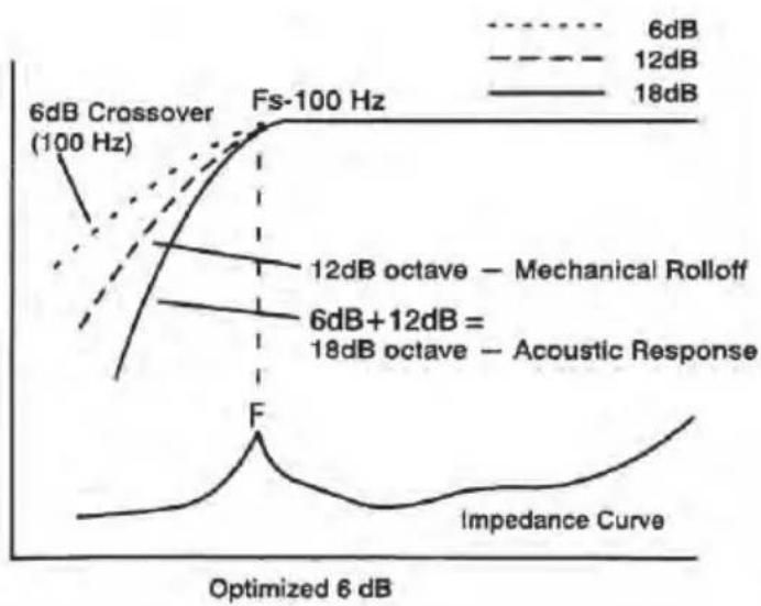
6 dB: When the high pass crossover frequency is set close to the speaker's resonant frequency, where the response rolls off at a rate of 12 dB per octave, switching the selector to the "6 dB" position would produce the ideal 18 dB odd order type phase response.
18 dB: When the crossover frequency is set away from the speaker's resonant frequency, switch the selector to the "18 dB" position for ideal 18 dB odd order type phase response.
9. HIGH-PASS OUTPUT LEVEL CONTROL
For adjusting the high-pass output signal level.
10. LEFT/RIGHT HIGH-PASS OUTPUT TERMINALS
To be connected to the mid/tweeter amplifier left/right inputs.
11. LOW-PASS FREQUENCY SELECTOR
For selection of the low-pass crossover frequency between 50 Hz, 63 Hz, 80Hz and 100 Hz.
12. LOW-PASS OUTPUT LEVEL CONTROL
For adjusting the low-pass output signal level.
13. LEFT/RIGHT LOW-PASS OUTPUT TERMINALS
To be connected to the woofer/subwoofer amplifier left/right inputs.
SYSTEM DIAGRAM

flowchart
graph TD
    A["PLHR2B PYLE"] --> B["Audio Module 1"]
    A --> C["Audio Module 2"]
    A --> D["Audio Module 3"]
    A --> E["Audio Module 4"]
    A --> F["Audio Module 5"]
    B --> G["Speaker 1"]
    C --> H["Speaker 2"]
    D --> I["Speaker 3"]
    E --> J["Speaker 4"]
    F --> K["Speaker 5"]
A Remote Turn-On Lead from Head Unit
B Battery Positive (B+)
INSTALLATIONS
CAUTIONS: Please follow all the installation recommendations and instructions in this manual, Installing and for using the electronic crossover in methods other than those outlined herein may reduce the performance capability of the crossover. Any such installation or usage may render the product warranty void.
A. LOCATION
- Select a mounting location that is easily and conveniently accessible, e.g. inside the trunk.
- To avoid damage to the crossover, keep the crossover away from any heat source (such as the engine or any heat- generating ducts).
- There should be adequate clearance above the crossover to allow easy adjustment.
B. WIRING LAYOUT
Once the location of all the components has been determined, plan the best routes for all the necessary wiring, making sure that the wires are easily accessible without dismounting the various components.
CAUTIONS: Routing audio cables and power cables together would invariably cause radiated engine noise in your audio system. If possible, run audio cables on one side of your car and power cables on the other. Never route these wires underneath the vehicle body.
- Check and make sure the vehicle s main battery and/or auxiliary battery, if any, is/are in good working condition and has sufficient capacity to run the electrical components of the vehicle plus the complete audio system.
-
The crossover is designed for use in 12 volt NEGATIVE GROUND electrical system ONLY. Installing the crossover in a vehicle with positive ground electrical system could result in serious damage to the electronic crossover, other audio components and/or the vehicle's electrical components.
-
FOR SAFETY, DISCONNECT THE BATTERY GROUND BEFORE INSTALLATION.
C. MOUNTING
- Place the crossover at the desired location and use it as a template to determine the exact position of the mounting holes. Mark the mounting holes with a pen.
- Use a center punch to ensure drilling the exact position for the screws. Drill four (4) 1/8 pilot holes. DO NOT BEGIN DRILLING UNTIL YOU HAVE PUT THE CROSSOVER ASIDE. USING THE CROSSOVER AS DRILLING GUIDE MAY CAUSE IRREPAPABLE DAMAGE TO THE COROSSOVER.
- Mount the unit with the Philips head sheet metal screws and steel washers provided.
D. WIRING
- Run the various wires according to your wiring layout, avoiding sharp edges and door jams.
- Electrical tape or grommets should be used to protect the wires when they are routed through bare metal holes.
Note:
The battery ground should remain DISCONNECTED at all stages of installation.
E. CONNECTIONS
- Connect the crossover to the Source Unit
Connect the outputs of the source unit to the inputs of the crossover (either via the low impedance input or the high impedance input).
- Connect the crossover to the Amplifiers
Connect the high-pass and low-pass outputs of the crossover to the inputs of their respective amplifiers.
- Connect the Amplifiers to the Speakers
Connect the various amplifiers to their speakers following the amplifier's manual and specifications.
- Connect the crossover to the Battery
Connect the power input cable to the positive terminal of the battery. Add circuit breaker to any power wire that runs through rewall or sheet metal to protect the battery, the vehicle, and more importantly, you.
5. Ground Connection
Connect the ground input cable of the crossover to the vehicle chassis. For better conductivity. If necessary, scrape paint off the chassis to reveal bare metal at the contact point.
6. Connect the Remote Input Terminal of the crossover to the Source Unit
Connect the remote input cable of the crossover to the remote output terminal of the source unit to establish crossover remote power on/off via the source unit. If the source unit does not provide a remote output, connect to its power antenna terminal or other switched 12-volt source, e.g. Ignition switch.
7. Reconnect the Battery Ground to the Vehicle Chassis
Double check all the previous installation steps with the following table. If everything is in order, complete the installation by reconnecting the battery ground to the vehicle chassis.
Installation
| Crossover Terminal Connected To | Terminal | |
| Left/Right High Impedance Inputs | Source Unit | Pre-amp Outputs |
| Left/Right Low Impedance Inputs | Source Unit | Speaker Outputs |
| Left/Right High Pass Outputs | Mid/Tweeter Amplifier | Left/Right Inputs |
| Left/Right Low Pass Outputs | Subwoofer Amplifier | Left/Right Inputs |
| Power Input Cable (B+) | Battery | Positive Terminal |
| Ground Input Cable (GND) | Vehicle Chassis | Bare Metal Spot |
| Remote Turn-on Input Cable | Source Unit | Remote Control Wire or Power Antenna Lead |
System Check
A. PRELIMINARY ADJUSTMENT
1. Pre Setting
a. Preset high-pass and low-pass amplifier input gain to half of their maximum.
b. Preset the crossover frequencies and output levels as follows:
High-Pass Frequency Selector: 125 Hz
Low-Pass Frequency Selector: 100 Hz
High-Pass Output Level: 10 o'clock position
Low-Pass Output Level: 10 o'clock position
c. Preset the volume of the source unit to its minimum (otherwise, when the source unit is turned on, the sudden surge of high power from the amplifiers might cause damage to the audio components).
2. Turn the source unit on and slowly turn the source unit volume up:
a. No Sound At All
- Turn the system off immediately.
- Check if connections are made properly (refer to sub-section titled CONNECTION for details).
- Use a Volt/Ohm meter to make sure good chassis ground established for each component that needs to be grounded.
- Check if the power input of all system components are properly connected to 12 volt positive power supply.
- Check if the remote on/off terminal of all system components are properly connected to positive 12-volt source.
- If everything is in order, turn the power on again. If the problem persists, refer to section titled TROUBLESHOOTING for assistance.
b. Obvious Distortion
Turn the system off and refer to section titled TROUBLESHOOTING for assistance.
c. Out-of-Phase Problem (Abnormal Bass) Turn the system off and refer to section titled TROUBLESHOOTING for assistance. If none of the above problems exists, proceed to the next step.
B. CROSSOVER FREQUENCY ADJUSTMENT
When setting the crossover frequencies, it is best to use compact discs or cassette tapes with greater dynamic range. Usually home recorded tapes are better in this respect than commercially recorded tapes.
System Check
- Center the tone, balance and fader controls of the source unit (leaving the other controls at their previous positions).
- Set the volume of the source unit to approximately 2/3 of its maximum output.
- Low-Pass Crossover Frequency Setting: Starting from 100 Hz, listen to the bass sound quality, if the bass is "Boomy" or soft sounding, select the low-pass frequency to other positions (80/63/50 Hz) until the bass sounds tight and deep. It is all a matter of personal preference. The optimum setting varies from vehicle to vehicle and from individual to individual. Subwoofer crossover frequency setting of as low as 80Hz is not uncommon.
- High-Pass Crossover Frequency Setting: Starting from 125Hz, adjust the high-pass frequency until you get your desired sound quality. Again, there is no universal optimum setting. It depends on the size and location of the front speakers and also your personal preference.
C. OUTPUT LEVEL ADJUSTMENT
As in the case of crossover frequency adjustment, when making the output level adjustment it is best to use compact discs or cassette tapes with greater dynamic range.
- Center the tone, balance and fader controls of the source unit (leaving the other controls at their previous positions).
- Set the volume of the source unit to approximately 2/3 of its maximum output.
-
With each of the crossover level controls, turn the level up or down until distortion develops, then retrace the path until distortion disappears.
-
Optimum output levels vary with the program source (radio, tape or CD). If the optimum output levels for radio differ considerable from those for tape/CD, locate the median levels that are best for both program sources.
D. CROSSOVER FILTER SLOPE SELECTION
When the high-pass crossover point is set close to the speaker's frequency response roll-off of 12 dB per octave (even order), by selecting the 6 dB per octave high-pass crossover slope, the combined effect is the ideal odd order (18 dB) filter type frequency response. When the high-pass crossover point is set away from the speaker's resonance frequency, the 18 dB per octave slope filter can be used.
E. NOISE CHECK
Before mounting the crossover and the other audio components permanently, please conduct the following noise check:
- Start the engine and turn on the power of the source unit.
-
Rev the engine and vary the audio volume to check for radiated engine noise. If there is an alternator whining noise or tic-tic noise, refer to the TROUBLESHOOTING for assistance.
-
If no unwanted noise is detected, double check all the wiring and cables for safe placement. Then securely tighten the mounting screws of all the audio components.
line
| Frequency | Condition | Value | | --------- | --------- | ----- | | 6dB | Crossover | 100 Hz | | 12dB | Mechanical Rolloff | - | | 6dB+12dB | Acoustic Response | - | | Optimized 6 dB | Impedance Curve | - |
line
| Frequency Range | Label | | --------------- | -------------------------- | | 12dB | Mechanical Rolloff | | Fs-100 Hz | Fc-100 Hz | | 300 Hz | 300 Hz | | 18dB | Electrical and Acoustical Response | | Impedance Curve | Impedance Curve |Optimized 6 & 18 dB Slope Selections
TROUBLESHOOTING
| SYMPTOM | PROBABLE CAUSE |
| No power | Check all the ground, B+ and remote cables for tight connection.Check all fuses.Use a Volt/Ohm meter to check all power wire connections to see if the system is receiving + 12V. |
| Motorboating:The crossover power indicator going off repeatedly when the audio system is on | Check if the crossover B+ power input is connected directly to the battery.Check the battery voltage; if low, recharge or replace it.Check if the crossover has a good ground connection (i.e. Whether the ground wire is making good contact with a bare metal spot of the vehicle chassis). |
| The crossover heats up quickly even when the audio system is at moderate volume. | Check all ground connections of the entire system for good contact with bare metal.Check for speaker short: Disconnect speaker wire from amplifier; test speaker and wire with a Volt/Ohm meter, if there is speaker and metal contact, slightly enlarge the speaker mounting holes, if there is a short in the speaker wiring, replace the entire speaker wire or re-insulate any exposed wire with electrical tape. |
| When the engine is running, the audio system has a whining noise that remains unchanged or disappears with the increase of audio volume. | Check all power wires to see if they are all connected directly to the battery.Check all the ground connections of the entire system for good contact with bare metal of the vehicle chassis.Check if the source unit and the crossover arc grounded at the same reference point. |
| When the engine is running, the audio system has a whining noise that increases or decreases with the volume of all program sources (wheather radio, tape or CD). | Install a 10 amp in-line filter on the red power wire of the crossoverIf the whining noise persists, check the alternator diodes and the voltage regulator. |
| When the engine is running, the audio system has a Whining noise that increases or decreases with the tape mode volume ONLY. | This is commonly known as "radiated noise. It is NOT caused by the crossover and thus is beyond the scope of this manual. Please contact your local retailer/installer for assistance. |
| Obvious distortion at low volume. | Output level of various channels not compatible, refer to section titled SYSTEM CHECK. |
| Overall sound effect good, but bass abnormal (more bass at the two extreme settings of the balance control than at the center setting). | The subwoofers are" out-of- phase" with each other, thus cancelling the bass when the balance control is at the center position. Check the wiring from the amplifier to the subwoofers (positive "+"to positive "+"and negative "-" to negative" -"). |
California Prop 65 Warning
! WARNING:
This product contains Nickel carbonate which is known to the state of California to cause cancer birth defects and other reproductive harm. Do not ingest.
For more info go to: www.P65warnings.ca.gov
PYLE
PyleUSA.com
Questions? Issues?
We are here to help!
Phone: (1) 718-535-1800
Email: support@pyleusa.com


- Specifications
- Features:
- What's in the Box:
- Technical Specs:
- Control Panel Layout
- FUNCTIONS
- POWER INPUT CABLE (12V)
- GROUND INPUT CABLE (GND)
- REMOTE TURN-ON INPUT CABLE
- POWER INDICATOR
- LEFT/RIGHT HIGH IMPEDANCE INPUT
- LEFT/RIGHIT LOW IMPEDANCE INPUT
- HIGH-PASS FREQUENCY SELECTOR
- HIGH-PASS FILTER SLOPE SELECTOR
- HIGH-PASS OUTPUT LEVEL CONTROL
- LEFT/RIGHT HIGH-PASS OUTPUT TERMINALS
- LOW-PASS FREQUENCY SELECTOR
- LOW-PASS OUTPUT LEVEL CONTROL
- LEFT/RIGHT LOW-PASS OUTPUT TERMINALS
- SYSTEM DIAGRAM
- INSTALLATIONS
- LOCATION
- WIRING LAYOUT
- MOUNTING
- WIRING
- Note:
- CONNECTIONS
- Ground Connection
- Connect the Remote Input Terminal of the crossover to the Source Unit
- Reconnect the Battery Ground to the Vehicle Chassis
- System Check
- PRELIMINARY ADJUSTMENT
- Pre Setting
- Turn the source unit on and slowly turn the source unit volume up:
- a. No Sound At All
- b. Obvious Distortion
- CROSSOVER FREQUENCY ADJUSTMENT
- OUTPUT LEVEL ADJUSTMENT
- CROSSOVER FILTER SLOPE SELECTION
- NOISE CHECK
- California Prop 65 Warning
- ! WARNING:
- PYLE
- PyleUSA.com
Brand : Pyle
Model : PLXR2B
Category : Blender