
PLXR3B - Blender Pyle - Free user manual and instructions
Find the device manual for free PLXR3B Pyle in PDF.


| Product Type | Blender |
| Brand | Pyle |
| Model | PLXR3B |
| Dimensions (H x W x D) | 15.5 x 7.5 x 7.5 inches |
| Weight | 6.5 lbs |
| Power | 500 Watts |
| Voltage | 120V / 60Hz |
| Jar Capacity | 48 oz (1.4 L) |
| Jar Material | Plastic (BPA-free) |
| Blade Material | Stainless Steel |
| Speed Settings | 2 speeds + Pulse |
| Functions | Blending, Pureeing, Crushing Ice, Mixing |
| Safety Features | Non-slip base, Lid lock, Overload protection |
| Cleaning and Maintenance | Hand wash jar and lid; wipe base with damp cloth |
| Spare Parts Availability | Replacement jars and blades available |
| Repairability | Designed for easy part replacement; customer support available |
| Included Accessories | Blender jar with lid, recipe booklet |
| Warranty | 1 year limited warranty |
| Country of Origin | China |
Frequently Asked Questions - PLXR3B Pyle
User questions about PLXR3B Pyle
0 question about this device. Answer the ones you know or ask your own.
Ask a new question about this device
Download the instructions for your Blender in PDF format for free! Find your manual PLXR3B - Pyle and take your electronic device back in hand. On this page are published all the documents necessary for the use of your device. PLXR3B by Pyle.
USER MANUAL PLXR3B Pyle
with Remote Subwoofer Control
USER GUIDE
INTRODUCTION
Your selection of an Audio bank car audio product indicates a true appreciation of fine musical reproduction. Whether adding to an existing system or including your Audio bank crossover in a new system, you are certain to notice immediate performance benefits.
KEEP YOUR SALES RECEIPT
Take this time to attach your sales receipt to the manual and put in a safe place. In case of any unforeseen reason this product may need warranty service. Your receipt will be necessary to establish purchase date.
RECOMMENDATION
A crossover's performance is only as good as its installation.
Proper installation will maximize the system's overall performance.
It is recommended that you have our product installed by an authorized Audio bank retailer. However, if you decide to install it yourself, please carefully read through this manual and take your time to do a quality installation.
IMPORTANT!
Before making any connections, disconnect the car's battery until the installation is completed to avoid possible damage to the electrical system.
WARNING!
Exposure to high power sound system can cause hearing loss or damage.
Listening to your system at loud levels while driving will impair your ability to hear traffic sounds and emergency vehicles.
Use common sense when listening to your system.
SYSTEM LAYOUT
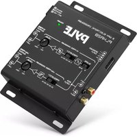
The primary function of the crossover is to filter the audio signal. Basically, the PLXR3B divides the audio signal into three separate pars..... Subwoofer, Mid and High. (See Figure #1).
Although the PLXR3B has rather simple connections, it is important for you to have a general understanding of the operating range of your system to properly setup the system as well as to make the final adjustments.


Full Range Output Three-way Output
(FIGURE # 1)
FULL RANGE VS. THREE-WAY OUTPUT
In order to reproduce the music in which it was recorded, your audio system should have the ability to recreate all audio information from 20Hz up to 20KHz (This is known as human audible range). One of the most important factors in sound quality is the overall balance of the frequency response, better known as the linearity of the sound. In a perfectly balance system, the low to high frequencies are reproduced without missing information. Unfortunately there are many factors that can cause loss of frequencies in your system. Some loss may be caused due your speaker's frequency response, crossover points, and level adjustment.
Before you set up the system it is best to first layout your system maintaining the speakers operating range. The following graph will give a general idea of the Subwoofer, Midrange and High operating range for the PLXR3B crossovers.

bar
| Frequency Range | Subwoofer | MID | HIGH | | --------------- | --------- | --- | ---- | | 20Hz | Low | - | - | | 40Hz | - | - | - | | 80Hz | - | - | - | | 160Hz | - | - | - | | 320Hz | - | - | - | | 640Hz | - | - | - | | 1.3KHz | - | - | - | | 2.6KHz | - | - | - | | 5.1KHz | - | - | - | | 10.2KHz | - | - | - | | 20KHz | - | - | - |(FIGURE # 2)
PLXR3B CROSSOVERS AND OPERATING RANGE
SAFETY PRECAUTIONS
Fuse crossover's power wire at the battery.
Be sure to fuse (3 amp) the power wire within 12" of the car's battery.
This will protect the car's battery in case of a short circuit between the crossover and the battery. THIS IS A MUST.
Use high grade wire connectors.
To ensure maximum power transfer and secure safe connections, it is recommended to use high grade barrier spades (for connection at crossover) and terminal rings (for connection at battery)..
Do not run any wires underneath vehicle
Exposed wires have a chance of being cut or damaged. It is best to run all wires through the vehicle under the carpet and/or side panels. This lends to a cleaner installation and less risk of damage.
Use caution when mounting the crossover.
Remember that there are many electrical wires, gas lines, vacuum lines, brake lines as well as a gas tank in the automobile. Make sure you know where they are when mounting the crossover to avoid puncturing lines, shorting wires or drilling holes in the gas tank.
Run signal wires away from electrical wires.
To avoid possibility of induced noise from the car's electrical system (i.e. popping noises or engine noise), run signal wires away from the car's electrical wiring.
Make all ground wires as short as possible and at the same point.
In order to reduce the chance of ground loops (i.e. engine noise), make the grounding wire as short as possible to reduce the wire's resistance. Also, when using multiple components, make sure all units are grounded at the same point.
Avoid sharp edges when running the wires.
To avoid the possibility of power, signal or speaker shorts, be careful not to allow the crossover's wires to come in contact with sharp edges.
Use a grommet to protect the wire when running through the firewall.
MOUNTING LOCATION
Select the location in which you wish to mount the crossover. It is recommended to find a location that will allow easy adjustment. Use caution when mounting crossover. There are many wires, gas lines, vacuum lines, brake lines as well as a gas tank in the automobile. Make sure you know where they are when mounting the crossover to avoid puncturing lines, shorting wires or drilling holes in the gas tank. Once you are ready use a pencil to mark the through holes in the bottom panel. After you have marked the locations of the holes move crossover out of the way and drill small starter holes to make the taping screws easier to install. Use provided screws to tighten down the crossover (see Figure # 3).
![PYLE® PLHR3B SUBWOOFER CROSSOVER BASS BOOST 70 80 150 40 400 Hz 0 Hcd LOW PASS FREQUENCY -ON - OFF SUB SONIC FILTER PHRSE -0 -180° SUBWOOFER OUTPUT LEVEL MIN MAX SUBWOOFER INPUT -ON - OFF SUB - DIRECT Y-CONNECT INPUT SUB - L- - R- SUB - MID - HI INPUTS OUTPUTS BASS CONTROL REMOTE +2U REM GROUND POWER FUSE HIGH PASS BAND PASS LOW PASS MODE FREQUENCY HIGH PASS 180 12H 60 2.8H 6S 4.5H Hz 5V0 3.8H 300 4.8H Hz REAR OUTPUT LEVEL MIN MAX HI CROSSOVER FREQUENCY MULTIPLIER HI- [Heo] POWER HIGH PASS FREQUENCY 6S 150 SS 250 Hz SS 400 Hz FRONT OUTPUT LEVEL MIN MAX](/content/2026/05/938785/images/126b81b6e7c2f9907a76138b7a5c0d953a05aba1a099bae2d82abde3acf71676.jpg)
(FIGURE #3)
MOUNTING THE CROSSOVER
POWER CONNECTIONS
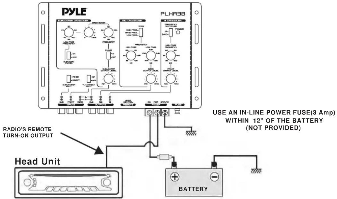
IMPORTANT!
Before making any connections, disconnect the car's battery until the installation is completed to avoid possible damage to the electrical system.
Connect the Power terminal of the crossover to the car's battery.
Use a 16 gauge wire to connect to the terminal on the crossover marked +12V. Run the wire directly to the positive terminal of the car's battery. Make sure to use an in-line fuse (3 amp) within 12' of the battery. Since the crossover's current draw is nominal, you can connect to the pre-existing + 12V power wire that has been run for the crossovers if so desired.
Connect the ground terminal of the crossover to the car's chassis.
Use a 16 gauge wire to connect the GROUND terminal to the car's chassis. Try to keep the length of the cable as short as possible, preferably less than 12". Also make sure that the point on the car chassis where the connection is to be made is free of paint and dirt. It is recommended to use the same grounding point as the amplifiers to eliminate the possibility of ground loop (engine noise) caused by different levels of ground to each of the components.
Connect the remote terminal of the crossover to a switchable +12V.
This connection allows the crossover to be turned on and off with the power control of the head unit. If the head unit has a REMOTE OUTPUT WIRE (+12V), connect it to the PLXR3B terminal marked REM. Now when the head unit is turned on, the crossover will automatically turn on. If the head unit does not provide a remote output, it is necessary to connect the crossover to a switched +12V power supply (when the car is on or in use).
SIGNAL CONNECTIONS
Before making your signal connections, you will need to decide how you wish to configure your system. The PLXR3B is extremely flexible allowing for many different configurations. All signal connections should be made using higher-grade RCA patch cables and these cables should be run away from electrical wiring to avoid inducted noise. The PLXR3B allows for three different types of input connections that control all three outputs of the crossover.
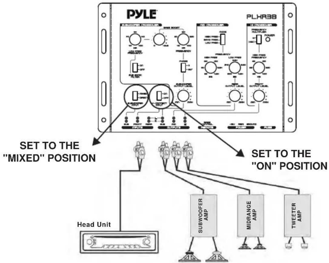
1. USING ONE PAIR OF PRIMARY INPUTS
When only one pair of input is available, input the signal into the "FRONT" input section and set the SUBWOOFER INPUT switch to "MIXED" and "Y-CONNECT INPUT" switch to "ON" position. This will allow the signals to be fed internally to the SUBWOOFER and REAR sections to give proper outputs.
flowchart
graph TD
    A["Head Unit"] --> B["Subwoofer AMP"]
    A --> C["Midrange AMP"]
    A --> D["Tweeter AMP"]
    B --> E["SET TO THE "ON" POSITION"]
    C --> E
    D --> E
    E --> F["SET TO THE "MIXED" POSITION"]
    style A fill:#f9f,stroke:#333
    style B fill:#ccf,stroke:#333
    style C fill:#cfc,stroke:#333
    style D fill:#fcc,stroke:#333
2. USING TWO PAIRS OF INPUTS
When front and rear pairs of input are available, input the signals into the "FRONT" and "REAR" inputs, respectively. Set the SUBWOOFER INPUT switch to "MIXED" position to allow the signals to be fed internally to the SUBWOOFER section to give proper outputs and set the "Y-CONNECT INPUT" switch to "OFF" position to allow control of fader from the head unit.

flowchart
graph TD
    A["Head Unit"] --> B["SET TO THE "MIXED" POSITION"]
    B --> C["SUBWOOFER INPUT"]
    B --> D["V-CONNECT INPUT"]
    B --> E["SUBWOOFER OUTPUT LEVEL"]
    B --> F["RESA OUTPUT LEVEL"]
    B --> G["FND OUTPUT LEVEL"]
    B --> H["SUB FRONT"]
    B --> I["REFR"]
    B --> J["L"]
    B --> K["R"]
    B --> L["OUTPUTS"]
    B --> M["MIN"]
    B --> N["MIN"]
    B --> O["BASE CONTROL"]
    B --> P["REMOTE"]
    B --> Q["+8V"]
    B --> R["ASM"]
    B --> S["GROUND"]
    B --> T["POWER"]
    B --> U["FUSE"]
    A --> V["SUBWOOFER AMP"]
    A --> W["MIDRANGE AMP"]
    A --> X["TWEETER AMP"]
3. USING THREE PAIRS OF INPUTS
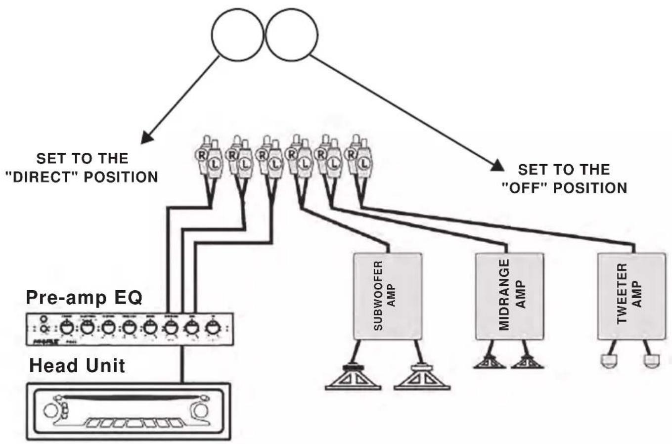
All three pairs of inputs on PLXR3B can be utilized when front, rear, and subwoofer pairs of inputs are available from a pre-amp EQ.
Set the SUBWOOFER INPUT switch to "DIRECT" position to allow independent subwoofer level control from the EQ and set the "Y-CONNECT INPUT" switch to "OFF" position to allow control of fader from the head unit. Note that some head units offer independent subwoofer output signals as well.
flowchart
graph TD
    A["Input"] --> B["SET TO THE "DIRECT" POSITION"]
    B --> C["Pre-amp EQ"]
    C --> D["Head Unit"]
    D --> E["Subwoofer AMP"]
    E --> F["Midrange AMP"]
    F --> G["Tweeter AMP"]
    G --> H["Output"]
    style A fill:#fff,stroke:#000
    style B fill:#fff,stroke:#000
    style C fill:#fff,stroke:#000
    style D fill:#fff,stroke:#000
    style E fill:#fff,stroke:#000
    style F fill:#fff,stroke:#000
    style G fill:#fff,stroke:#000
    style H fill:#fff,stroke:#000
SELECTING THE CROSSOVER POINTS
![PYLE® PLHR3B SUBWOOFER CROSSOVER BASS BOOST 70 60 40 400 Hz 0 +16dB LOW PASS FREQUENCY -ON -OFF SUB SONIC FILTER FREQUENCY PHASE 0 -180° SUBWOOFER OUTPUT LEVEL min max SUBWOOFER INPUT -MHED -DIRECT Y-CONNECT INPUT -ON -OFF SUB FRONT REAR -L- -R- SUB MD HI OUTPUTS BASS CONTROL REMOTE +12V REM GROUND POWER FUSE HI CROSSOVER FREQUENCY MULTIPLIER HI- [H2O] POWER HIGH PASS FREQUENCY 6S 150 SS 250 9S 400 Hz REAR OUTPUT LEVEL min max FRONT OUTPUT LEVEL min max INPUTS OUTPUTS](/content/2026/05/938785/images/0877553f663fd64c02ad616949b405ecff2637a3c996b4d75aa9ee6535323197.jpg)

1. SETTING THE SUBWOOFER CROSSOVER POINT, BASS BOOST, PHASE, and SUB SONIC FILTER
Set the desired CROSSOVER FREQUENCY tor the subwoofer output using the LOW PASS FREQUENCY dial. You may select from 40Hz up to 400Hz as your crossover point.
Set the BASS BOOST by using the two dials. Use the LEVEL dial to set the boost gain from 0 to 18dB. and use the FREQUENCY dial to set the bass boost frequency point from 40Hz up to 400Hz.
Select the PHASE of the subwoofer using the PHASE switch, 0 degrees in phase or 180 degrees out of phase. The normal default setting is 0 degrees in phase.
SUBSONIC FILTER may be turned on/off by using the SUBSONIC FILTER switch.
When switched on, this Filter avoids reproduction of inaudible low frequencies below 25Hz which could damage the subwoofer(s) because they can generate over displacement of the subwoofer cone. It is recommended that the SUBSONIC FILTER be switched ON.
2. SETTING THE CROSSOVER POINTS FOR THE REAR (MIDRANGE) OUTPUT
Usually the MID output is a BAND PASS design. It's achieved by setting the MODE switch at "BAND PASS" and using both HIGH PASS and LOW PASS FREQUENCY dials. Set the desired HIGH PASS frequency anywhere between 65Hz and 300Hz for the low frequency cutoff, and set the desired Low PASS frequency anywhere between 2.9KHz and 4.8KHz for the high frequency cutoff.
Selecting HIGH PASS from the MODE switch and using HIGH PASS FREQUENCY dial alone will remove the high cutoff section and allow the midrange output to play up to 20KHz.
Selecting LOW PASS from the MODE switch and using LOW PASS FREQUENCY dial alone will remove the low cutoff section and allow the midrange output to play down to 20Hz. This setting will be ideal if you're using mid bass speakers capable of reproducing low to mid frequencies.
3. SETTING THE CROSSOVER POINT FOR THE FRONT (HIGH) OUTPUT
Set the desired frequency cutoff point using the HIGH PASS FREQUENCY dial for your HIGH output, such as tweeters. The FREQUENCY MULTIPLIER switch must be set at "x20" in order to obtain the frequency range from 700Hz to 8KHz.
You also have an option of reproducing mid bass or midrange level in the FRONT by using the cutoff frequency range from 30Hz to 400Hz with the FREQUENCY MULTIPLIER switch at "x1".
One very important part of fine tuning your system is properly level matching the signal from the head unit to the PLXR3B crossover and from the crossover to the amplifiers. Level matching is the process of calibrating the audio signal from the head unit all the way to the amplifiers to eliminate unwanted noise and maximize the dynamic: headroom. When the system is properly adjusted, you should achieve maximum output before distortion at about 3/4 volume on the head unit.
MATCHING THE SIGNAL LEVEL
Note: If you have pre-amp Equalizer in the system, bypass or turn off the equalization while level matching.
- Turn all three output level dials on PLXR3B (Subwoofer, Rear, and Front) to maximum position.
- Turn the BASS BOOST LEVEL dial on PLXR3B to 0.
- Turn all input sensitivity gain control knobs on output amplifiers to minimum position.
- Turn on the system and increase the head unit's volume to 3/4 high (75% of Max volume).
- Very slowly increase the input sensitivity gain on each amplifier to the point right before the speakers go into distortion. Use CAUTION not to overdrive the speakers. Do this for all three amplifiers one by one.
Once all adjustments are made, the system should sound clear without distortion up to 3/4 of main volume. Also the volume should increase very evenly.
Once you complete matching the signal level, the following steps ought to be made to set the overall linearity of the system.
This may be necessary due to the relative efficiencies of each of the speakers.
For example, smaller speakers normally are more efficient then woofers and play louder faster at given equal power (See Figure # 4)
The PLXR3B's individual output level controls allow compensation for this.
It is important to understand that the output levels are not designed to add gain to the signal. Actually, the output level controls attenuate (reduce signal gain).
It is for this reason that in the following steps we will start with the output levels at the maximum position then reduce the outputs to balance the system.
For example, if you like heavy bass, you will most likely leave the SUBWOOFER OUTPUT LEVEL at the maximum position and reduce the MID and HIGH output levels by 1/2 (50%). This will allow the bass to reach a high output faster than MID and HIGH speakers.
If you wish to increase the MID and HIGH frequencies, reduce the SUBWOOFER OUTPUT LEVEL.

line
| Platform | Value | | ---------- | ----- | | Subwoofer | 100 | | Midrange | 100 | | Tweeters | 100 |(FIGURE #4)
VISUAL EXAMPLE OF DIFFERENT OUTPUT LEVELS BASED ON THE SAME POWER INPUT.
TROUBLESHOOTING THE SYSTEM
We have put together this troubleshooting guide if you experience problems after installing the crossover. Please keep in mind that the majority of problems incurred are caused by improper installation and not the equipment itself.
In addition, there are many components in the system that could cause various signal problems such as inducted electrical noise and engine noise.
Before you can properly address the problem, you must first find the component that is causing the problem. This will take patience and process of elimination.
LOOK FOR....
No Output
Blown fuse
Bad RCA Cable(s)
+12V at power terminal
+ 12V at remote terminal
Grounding point clean and tight
Head Unit's fader not in center position
SOLUTION
Replace
Replace
Check connection
Check connection
Check for ground w/meter
Set to center position
Low Output
Check level adjustments
Bad RCA cables(s)
Improper level matching
Re-adjust
Replace
Re-adjust
Engine Noise
Grounding points are clean and tight
Ground all components at same point
Try different grounding point
Bad RCA cable(s)
Use High Quality shielded RCA cable
Low Vehicle charging system and /or battery
Check for ground w/meter
Ground at same point
Change for better ground
Replace
Rejects inducted noise
Fix and 1 or replace.
California Prop 65 Warning
! WARNING:
This product contains Nickel carbonate which is known to the state of California to cause cancer birth defects and other reproductive harm. Do not ingest.
For more info go to: www.P65warnings.ca.gov
Features:
• 3-way Electronic Crossover
• 2/4/6 Channel Input
- 6-Channel / 5 Volt RCA Outputs (Front/Rear/Subwoofer)
- Front/Rear/Subwoofer Lever Control
- Subwoofer Equalizer and Boost Level Controls
- Subwoofer Low-Pass Crossover Control
• 6/4/2 Channel RCA Inputs
- 6-Channel / 5 Volt RCA Outputs (Front/Rear/Subwoofer)
• X20 Frequency Multiplier for Front Channel
- Low-Pass Crossover
• 12dB per Octave Crossover Slope
- Parallel Input Switch, Mixed In/Out Switch
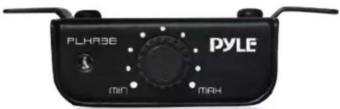
- Remote Subwoofer Level Control
• Power on LED Indicator
What's in the Box:
• 3-Way Electronic Crossover
• 4 Phillips-head Screws
- Remote Unit
- Remote Wire
- 3A Chip Fuse
Technical Specs:
• Hi-Pass Crossover (Front): 35Hz-400Hz
• Hi-Pass Crossover (Rear): 65Hz-4.5 KHz
- Low-Pass Crossover (Rear): 300Hz-4.8 KHz
• Variable Bass Frequency: 40Hz-400Hz
- Boost Level: 0-18dB
- Boost Frequency: 40Hz-400Hz
- Phase Shift: 0 / 180
- Subsonic: 25Hz
• Distortion: 0.05% THD at 1V output level
• S/N Ratio: 110dB
- Separation: >60dB
• Frequency Response: 10 HZ\~ 50 KHZ
• Voltage: 11V-15V
- Product Dimensions (L x W x H): 10.4" x 6.3" x 1.5"-inches
![PYLE® PLHR3B SUBWOOFER CROSSOVER BASS BOOST 60 40 40 Hz LOW PASS FREQUENCY -ON -OFF SUB SONIC FILTER SUBWOOFER OUTPUT LEVEL -MHED -ORECT -ON -OFF SUBWOOFER INPUT Y-CONNECT INPUT SUB FRONT REAR L- A- SUB MID H- OUTPUTS BRS CONTROL REMOTE +2U RED GROUND POWER FUSE HIGH PASS- BAND PASS- LOW PASS- MODE FREQUENCY HIGH PASS 160 12H 60 2.3H 65 4.5H Hz LOW PASS 2.0H 5J0 3.9H 300 4.8H Hz REAR OUTPUT LEVEL MN MAH HI CROSSOVER FREQUENCY MULTIPLER POWER HI- [400]- HIGH PASS FREQUENCY 85 50 55 250 35 400 HE FRONT OUTPUT LEVEL MN MAH](/content/2026/05/938785/images/e279e59aa013d5f7c282b83d9dfe41e6a7f02e8264eea14d566ba351ea6ab23c.jpg)
PYLE
PyleUSA.com
Questions? Issues?
We are here to help!
Phone: (1) 718-535-1800
Email: support@pyleusa.com

- INTRODUCTION
- KEEP YOUR SALES RECEIPT
- RECOMMENDATION
- IMPORTANT!
- WARNING!
- SYSTEM LAYOUT
- Full Range Output Three-way Output
- (FIGURE # 1)
- FULL RANGE VS. THREE-WAY OUTPUT
- SAFETY PRECAUTIONS
- Fuse crossover's power wire at the battery.
- Use high grade wire connectors.
- Do not run any wires underneath vehicle
- Run signal wires away from electrical wires.
- Make all ground wires as short as possible and at the same point.
- Avoid sharp edges when running the wires.
- MOUNTING LOCATION
- POWER CONNECTIONS
- Connect the Power terminal of the crossover to the car's battery.
- Connect the ground terminal of the crossover to the car's chassis.
- Connect the remote terminal of the crossover to a switchable +12V.
- SIGNAL CONNECTIONS
- USING ONE PAIR OF PRIMARY INPUTS
- USING TWO PAIRS OF INPUTS
- USING THREE PAIRS OF INPUTS
- SETTING THE SUBWOOFER CROSSOVER POINT, BASS BOOST, PHASE, and SUB SONIC FILTER
- SETTING THE CROSSOVER POINTS FOR THE REAR (MIDRANGE) OUTPUT
- SETTING THE CROSSOVER POINT FOR THE FRONT (HIGH) OUTPUT
- MATCHING THE SIGNAL LEVEL
- TROUBLESHOOTING THE SYSTEM
- LOOK FOR....
- No Output
- SOLUTION
- Low Output
- Engine Noise
- California Prop 65 Warning
- ! WARNING:
- Features:
- What's in the Box:
- Technical Specs:
- PYLE
- PyleUSA.com
Brand : Pyle
Model : PLXR3B
Category : Blender