
CDR0420 - Voice recorder Clover Electronics - Free user manual and instructions
Find the device manual for free CDR0420 Clover Electronics in PDF.


| Product Type | Voice Recorder |
| Brand | Clover Electronics |
| Model | CDR0420 |
| Recording Format | MP3, WAV |
| Internal Memory | 8 GB |
| Battery Capacity | 400 mAh, 3.7V, Rechargeable Li-ion |
| Dimensions | 4.2 x 1.8 x 0.5 inches (106 x 46 x 13 mm) |
| Weight | 1.6 oz (45 g) |
| Power Source | USB charging (5V DC) or battery |
| Recording Time | Up to 48 hours (in lowest quality) |
| Frequency Response | 20 Hz – 20 kHz |
| Signal-to-Noise Ratio | ≥80 dB |
| Microphone | Built-in omni-directional |
| Display | 1.0-inch OLED |
| Controls | Power, Record, Play/Pause, Stop, Volume, Menu |
| Connectivity | USB 2.0, microSD card slot (up to 32 GB) |
| Voice Activation | Yes (VOR) |
| Password Protection | Yes |
| Package Contents | Voice recorder, USB cable, earphones, user manual |
| Maintenance | Clean with dry cloth; avoid moisture and dust |
| Safety Warnings | Do not disassemble; keep away from water and extreme temperatures |
| Spare Parts / Repairability | USB cable and earphones available separately; user replaceable battery |
| General Information | User manual can be downloaded from Clover Electronics website |
Frequently Asked Questions - CDR0420 Clover Electronics
User questions about CDR0420 Clover Electronics
0 question about this device. Answer the ones you know or ask your own.
Ask a new question about this device
Download the instructions for your Voice recorder in PDF format for free! Find your manual CDR0420 - Clover Electronics and take your electronic device back in hand. On this page are published all the documents necessary for the use of your device. CDR0420 by Clover Electronics.
USER MANUAL CDR0420 Clover Electronics
natural_image
Vertical arrangement of white geometric shapes on black background, no text or symbols present
natural_image
Abstract black-and-white geometric shapes including clover, starburst, arrow, and flower (no text or symbols)
natural_image
Five black-and-white geometric symbols: star, snowflake, asterisk, snowflake, and square (no text or labels)
natural_image
Row of abstract geometric symbols including asterisks, stars, and rectangles (no text or labels)


CAUTION!
RISK OF ELECTRIC SHOCK. PLEASE DO NOT REMOVE COVER WHEN POWER CONNECTED. NO USER SERVICEABLE PARTS INSIDE. REFER SERVICING TO QUALIFIED SERVICE PERSONNEL.

WARNING
TO PREVENT FIRE OR ELECTRIC SHOCK HAZARD, DO NOT EXPOSE THIS APPLIANCE TO RAIN OR MOISTURE.

NOTE: This equipment has been tested and found to comply with the limits for a Class “A” digital device, pursuant to Part 15 of the FCC Rules. These limits are designed to provide reasonable protection against harmful interference when the equipment is operated in a commercial environment. This equipment generates, uses, and can radiate radio frequency energy and, if not installed and used in accordance with the instruction manual, may cause harmful interference to radio communications.

FCC Caution: To assure continued compliance, use only shielded interface cables when connecting to computer or peripheral devices. Any changes or modifications not expressly approved by the party responsible for compliance could void the user's authority to operate this equipment.

This Class A digital apparatus meets all the requirements of the FCC Regulations.
CE
LIMITATION OF LIABILITY
This users' manual is supplied ‘as is’, with no warranties, be it expressed or implied, including, but not limited to, the implied warranties of merchantability, suitability for any exact purpose, or non-infringement of any third party's rights.
This publication may include technical inaccuracies or typos. The manufacturer holds the right to introduce any changes to the information contained herein, for any purpose, including but not limited to, improvements of the publications and/or related to the product, at any time, without prior notice.
DISCLAIMER OF WARRANTY
The supplier shall not be liable to any party or any person, except for replacement or reasonable maintenance of this product, for the cases, included but not limited to the following:
■ Any damage or loss, including but not limited to: direct/indirect, consequential, special, exemplary use arising out of or related to the product;
■ Inappropriate use or negligence of the user in operation of the product, resulting in personal injury or any damage;
■ Unauthorized disassembly, repair or modification of the product by the user;
■ Any problems or consequential inconvenience, loss or damage, caused by connecting this product to devices of the third parties;
■ Any claim or action for damages, brought by any photogenic subject, be it a person or organization, due to violation of privacy whereby the surveillance picture and/or saved data becomes public or is used for the purpose other than surveillance.
SAFETY INSTRUCTIONS
- Read these instructions and keep them in a safe place for future reference.
■ Please refer all work related to the installation of this product to qualified service personnel or system installers.
■ Do not operate the appliance beyond its specified temperature, humidity or power source ratings.
■ Place the unit on a flat surface not prone to vibration or impact.
■ Use the appliance at temperatures between 0 ^ +45 ^ ( 32^ 113^ ) and humidity below 85%.
■ Install the unit away from heat sources such as radiators, heat registers and stoves. Installation of the unit near consumer electronics devices, such as stereo receiver/amplifiers and televisions, is permitted as long as the air surrounding the terminal does not exceed the above mentioned temperature range.
■ Handle hard disk drives (HDD) with care.
It is possible to damage hard drives if they are moved while their motors are still running. To allow the hard drive to spin down and park its heads, wait at least 10 seconds after disconnecting power before moving the unit.
To avoid shock and vibration damage to the internal hard drive, do not move the unit while it is plugged in.
Protect hard disk drives from static electricity.
Do not stack hard disk drives or keep them upright.
Do not use an electric or magnetic screwdriver to fix hard disk drives.
- Do not place the unit in an enclosed area where the cooling vents are blocked or impede the flow of air through the ventilation openings.
■ Protect the power cord from being stepped on or pinched particularly at plugs and the points where they exit from the apparatus. -
Do not drop metallic parts through slots. This could permanently damage the appliance. Turn the power off immediately and contact qualified service personnel for service.
■ Handle the appliance with care. Do not drop or shake, as this may damage the device. -
Do not expose the appliance to water or moisture, nor try to operate it in wet areas. Do not install the unit in an area where condensation occurs. Do not operate with wet hands. Take immediate action if the appliance becomes wet. Turn the power off and refer servicing to qualified service personnel. Moisture may damage the appliance and also cause electric shock.
■ Do not use strong or abrasive detergents when cleaning the appliance body. When the dirt is hard to remove, use a mild detergent and wipe gently.
■ Do not overload outlets and extension cords as this may result in a risk of fire or electric shock.
■ Please make a note of your settings and save them. This will help when you are required to change the system configuration, or when an unexpected failure or trouble occurs.
■ Distributing, copying, disassembling, reverse compiling, reverse engineering, and also exporting in violation of export laws of the software provided with this product, is expressly prohibited.

CARING FOR THE ENVIRONMENT BY RECYCLING
When you see this symbol on a product, do not dispose of the product with residential or commercial waste.
Recycling your Electrical Equipment
Please do not dispose of this product with your residential or commercial waste. Some countries or regions, such as the European
Union, have set up systems to collect and recycle electrical and electronic waste items. Contact your local authorities for information about practices established for your region
COPYRIGHT STATEMENT
All rights reserved. No part of this publication may be reproduced in any form or by any means, transcribed, translated into any language or computer language, transformed in any other way, stored in a retrieval system, or transmitted in any form or by any means, electronic, mechanical, recording, photocopying or otherwise, without the prior written permission of the owner.
Table of Contents
LIMITATION OF LIABILITY....3
DISCLAIMER OF WARRANTY....3
SAFETY INSTRUCTIONS ....3
COPYRIGHT STATEMENT 5
TABLE OF CONTENTS....6
-
YOUR DVR AT A GLANCE .... 10
-
CONTENTS OF THE BOX....13
2.1 GETTING STARTED CHECK-LIST....13
- HARDWARE....13
3.1 FRONT PANEL (PLEASE TAKE ACTUAL MACHINE MODEL AS QUASI) 13
3.2 BACK PANEL (PLEASE TAKE ACTUAL MACHINE MODEL AS QUASI)....16
3.3 REMOTE CONTROL....20
3.4 MOUSE CONTROL 22
3.5 HARDWARE INSTALLATION 23
3.5.1 Basic Connections....23
3.5.2 Installing Hard Disk Drive....24
3.5.3 PTZ Control Connections---- (optional)....26
- GETTING STARTED AND THE MAIN SCREEN....26
4.1 THE MAIN SCREEN ....26
4.1.1 Displaying a Single Channel ....27
4.1.2 Login System 27
4.1.3 Shortcut menu 28
4.2 SHORTCUT MENU OPTIONS....29
4.2.1 Main Menu....29
4.2.2 Record Playback 29
4.2.3 Video Backup....31
4.2.4 Record Control....34
4.2.5 Alarm Output....34
4.2.6 PTZ Control 35
4.2.7 Color Setting ....36
4.2.8 TV Adjustment....37
4.2.9 Logout ....37
4.2.10 Screen View Modes ....37
4.3 CHANNEL STATUS DISPLAY .... 38
5. DVR SETTINGS....38
5.1 MAIN MENU....38
5.1.1 Menu Options....41
5.2 RECORD SETTINGS....41
5.2.1 Schedule....41
5.2.2 Search 43
5.2.3 Record Backup....43
5.3 ALARM SETTING 43
5.3.1 Motion Detection 43
5.3.2 Camera Masking 45
5.3.3 Video Lost 47
5.3.4 Alarm Input ....48
5.3.5 Alarm Output....50
5.3.6 Abnormity ....50
5.4 SYSTEM SETTINGS ....51
5.4.1 General Setting....51
5.4.2 Encode Setting....52
5.4.3 Network Setting....53
5.4.4 Display Setting....57
5.4.5 Account Setting....58
5.4.6 PTZ Setting....61
5.4.7 RS232....62
5.4.8 Tour Setting....62
5.5 ADVANCED SETTING 63
5.5.1 HDD Manage....63
5.5.2 USB Upgrade....64
5.5.3 Configuration....64
5.5.4 Maintenance....65
5.5.5 Default....65
5.5.6 Shut Down....66
5.6 INFORMATION....66
5.6.1 HDD Information....67
5.6.2 BPS....68
5.6.3 Log....68
5.6.4 Version....69
6. WEB BROWSER OPERATION....69
6.1 SOFTWARE ENVIRONMENT 69
6.2 NETWORK SECURITY SETTING....70
6.3 CONNECTION SETTING....71
6.4 CONTROL DOWNLOAD AND INSTALLATION....73
6.5 OPERATION INTERFACE....74
6.5.1 Live....74
6.5.2 Connecting cameras....75
6.5.3 Functions on View 75
6.5.4 PTZ Control 77
6.5.5 Image Adjustment....77
6.5.6 Others operation....77
6.6 RECORD QUERY 78
6.7 ALARM CONFIG....78
6.8 SYSTEM CONFIG 79
6.8.1 System Info 79
6.8.2 System Setting....80
6.8.2.1 General Setting 80
6.8.2.2 Encode 80
6.8.2.3 Record Setting 81
6.8.3 Net Setting....82
6.8.3.1 Main Setting....82
6.8.3.2 DNS Setting....83
6.8.3.3 DDNS Setting....83
6.8.3.4 UPNP 83
6.8.4 Alarm Setting 84
6.8.4.1 Alarm In....84
6.8.4.2 Alarm output....84
6.8.5 Advanced Option....85
6.9 ABOUT....86
6.10 LOGOUT 86
7. MOBILE PHONE SUPPORT ....86
7.1 WINDOWS MOBILE 86
7.2 SYMBIAN PHONE....88
7.5 APPLE IPHONE....97
APPENDIX 1 SETTING UP INTERNET CONNECTIONS FOR REMOTE ACCESS....101
APPENDIX 2 COMPATIBILITY TABLE FOR HDDS ....101
APPENDIX 3 LIST OF COMPATIBLE PORTABLE USB DVD RECORDERS....102
APPENDIX 4 LIST OF COMPATIBLE PORTABLE SATA DVD RECORDERS (ONLY FOR 8CH AND 16CH D1 SERIES)....103
APPENDIX 5 LIMITED 1YEAR WARRANTY....103
APPENDIX 6 HOW TO OBTAIN FACTORY SERVICE....103
1. YOUR DVR AT A GLANCE
Product Overview
D 1
| Model 4CH 8 | CH 16 CH | ||
| Video Format | PAL/NTSC | ||
| Video Compression | 11.264 Baseline Compression | ||
| Video Input / Output | BNC 4 Input /CVBS output/ VCA output | BNC 8 Input / CVBS Output/Spot Out/Video Loop/VGA Output/ HDMI | BNC 16 Input / CVBS Output/Spot Out/Video Loop/VGA Output/ HDMI |
| Audio Format | G.711a | ||
| Audio Input / Output * | RCA 4 Input/1Output | BNC 8 Input /1 Line in/Microphone/ 1 Output | BNC 16 Input /1 Line in/Microphone/ 1 Output |
| Alarm Type* | Motion detection, Sensor Input, Relay Output , Video Loss, Camera masking, No Disk space, Disk error, Not enough space, Network failure, and IP Conflict | ||
| Sensor In / Out* | 4CH Input/1CH Output | 16CH Input / 4 CH Output | |
| Display Frame Rate | Each Channel PAL:25 FPS, NTSC:30 FPS | ||
| Playback Resolution | CIF/Half-D1/D1 @ Recorded frame rate | ||
| Record Frame Rate | PAL: 100FPS@CIF, 100FPS@IID1, 100@D1 NTSC:120FPS@CIF,120FPS@IID1,120@D1. | PAL: 200 FPS@CIF, 200 FPS@IID1, 200 FPS@D1 NTSC: 240FPS@CIF,240 FPS@IID1,240 FPS@D1. | PAL: 400 FPS@CIF, 400 FPS@IID1, 400 FPS@D1 NTSC: 480FPS@CIF,480 FPS@IID1,480 FPS@D1. |
| Record method | Scheduled Record (Normal Record, Motion Detection, Alarm Trigger), Manual Record | ||
| HDD Interface | Up to 2TB, SATA interface HDD*1 | Each up to 2TB for each one, SATA interface HDD*8 or HDD*6+DVD+RW | |
| Network Protocol | TCP-IP/ DHCP/DDNS/PPPOE/E-Mail/NTP/FTP/ RTSP/ IP Filter/ UPNP | ||
| Network Function | Live Monitor, Playback, Configuration, Backup, Mobile Phone Surveillance | ||
| USB2.0 Interface | Mouse / Portable Mobile HDD/ Flash Drive/ USB DVD Burner | ||
| Playback method | Normal, Fast Forward, Slow Forward, Rewind, Single Step | ||
| Network Interface | RJ45 100M/ 1000M Ethernet Auto Detect | ||
| PTZ Protocol* | PELCO-P , PELCO-D,PANASONIC, SONY, etc | ||
| Area Covered | Support area covered for each channel | ||
| Video Backup | Backup files in DAV or AVI format for USB disk and in DAV format for USB DVD burner. | ||
| Power Adapter | DC 12V 3A AC 220 | V/12V 5A |
| Operating temperature | -10°C~+40°C | |
| Operating humidity | 10%~90% | |
| Dimensions* (L*W*H) | 315x232x57mm 430* | 443*96mm |
CIF
| Model | 4CH 8CH 16CH | ||
| Video Format | PAL/NSTC | ||
| Video Compression | H.264 Baseline Compression | ||
| Video Input / Output | BNC 4 Input/ 1 Output | BNC 8Input/1 Output | BNC 16 Input / 1 Output |
| Audio Format | G.711a | ||
| Audio Input / Output * | RCA 4 Input/ 1 Output DB-9 8 Input / 1 Output | ||
| Alarm Type* | Motion detection, Sensor Input, Relay Output , Video Loss, Camera masking | ||
| Sensor In / Out* | 4CH Input / 1CH Output | ||
| Display Frame Rate | Each Channel PAL:25 FPS, NTSC:30 FPS | ||
| Playback Resolution | CIF/HD1/D1 @ Recorded frame rate | ||
| Record Frame Rate | PAL:100FPS@CIF, 100FPS@HD1, 100FPS@D1;NTSC:120FPS@CIF, 120FPS@HD1, 120FPS@D1; | PAL:200FPS@CIF;NTSC:240FPS@CIF; | PAL:400FPS@CIF;NTSC: 480FPS@CIF; |
| Record method | Scheduled Record (Normal Record, Motion Detection, Sensor Trigger, Video Loss, Camera Masking), Manual Record | ||
| HDD Interface | Up to 2TB,SATA interface HDD*1 | Up to 1TB,SATA interface HDD*1 | Each up to 1TB,SATA interface HDD*2 |
| Network Protocol | TCP-IP/ DHCP/PPPOE/NTP/FTP/ RTSP/ UPNP | |
| Network Function | Live Monitor, Playback, Configuration, Backup, Mobile Phone Surveillance | |
| USB 2.0 Interface | Mouse/USB flash disk | Mouse / Portable Mobile HDD/ Flash Drive/ DVD Burner/ Firmware Upgrade |
| Playback method | Normal, Fast Forward, Slow Forward, Rewind, Single Step | |
| Network Interface | RJ45 10M/ 100M Ethernet Auto Detect | |
| PTZ Protocol* | PELCO-P , PELCO-D,PANASONIC, SONY, etc | |
| Area Covered | Support area covered for each channel | |
| Video Backup | Backup files in DAV and AVI format. | |
| Power Adapter | DC 12V Adapter | |
| Operating temperature | -10°C~+40°C | |
| Operating humidity | 10%~90% | |
| Dimensions (L x W x H) * | 315 x 232 x 57 mm 435 x 380 x 52 mm | |
Model dependent
Congratulations on purchasing your state-of-the-art Digital Video Recorder (DVR) offering the industry's best triplex functionality with video/audio recording, playback, and network capability. Your new device allows you to run all three functions simultaneously, streamlining the use of your CCTV system and boosting the security level of your home, business or social venue. You can access live or recorded feed from your standard or PTZ cameras immediately at the location of the DVR installation, or anywhere in the world using web-browsers or a mobile phone*. The video may be stored at a remote location for safety.
(*Some limitations apply to web and phone-based features, please see the related sections for detailed description.)
Please get acquainted with the parts and accessories as well as the ways to use the appliance as described in this instruction manual. If you have any questions that this guide cannot answer, please contact your vendor or a certified specialist.
2. Contents of the Box
- DVR device
- Installation CD
- Remote control
- Power cord
- Mouse (optional, depends on the model)
- Hard disk drive (optional, depends on the model)
2.1 Getting Started Check-List
Before starting to work with your new DVR, please make sure all relevant connections are done correctly.
a) Are the power and video in/out cables plugged in? Please see Section 3.5.1 Basic Connections for more.
b) Is the HDD installed? Please see Sections 3.5.2 Installing Hard Disk Drive for more.
c) Did the DVR start recording? Please see Section 4.2.4 Record Control for more.
3. Hardware
3.1 Front Panel (Please take actual machine model as quasi)
Front panels are different in term of different machine model. The front panels as follows are for reference.
4 CH
| No. | Name | Icon | Function |
| 1 | Quad |  | Press this button to switch the display modes |
| Channel switch | CH1,CH2, CH3,CH4 | Using these buttons allows you to choose to output video on your monitor either as a full-screen view of each of the cameras individually | |
| 2 | Menu | Menu | Access tool bar |
| 3 | ESC ESC Close upper interface or controls. | ||
| 4 | REC | REC | Manually stop/start recording |
| 5 | DEL | DEL | Assistant function: delete the character that you input in the textbox. |
| 6 | Play/Pause | [X2A4] | Button enables Play-back or Pause mode |
| 7 | PTZ PTZ PTZ control, enter the PTZ control mode | ||
| 8 | Up/down | [XXDH] | Shift current control, modify setup, increase/decrease numerals, assistant function for PTZ menu |
| Switch tab in main menu. | |||
| Left/right | [AXSA] | Shift current activated control. When playback, click these buttons to control the playback bar. | |
| Enter | Enter | Confirm/Select current operation | |
| System menu in the Review window | |||
| 9 | LED | Power LED lights indicate your connection to the power supply | |
| HDD LED lights indicate recording status. | |||
| 10 | IR Remote Control | [WAZA] | Receive remote control signal |
8/16CH
| S/N | Name | Icon | Function |
| 1 | Power- (optional) |  | Power button, press and hold for 3 seconds to shut down DVR. |
| 2 | Remote control | IR | Receive remote control signal |
| 3 | USB | USB | Use these USB ports to connect the mouse and backup devices (flash drive, DVD recorder). |
| 4 | indicator Light- (optional) | 1-16 | 1-16 Channel indicator Light |
| 5 | Menu | Menu^ | Access the Tool bar |
| 5 | Numeral | 0-9 | Numeral | Letter | Character |
| SHIFT- (optional) |  | Switch between function and numeral | |
| 10+ | 10+ | Switch above 10+ channels | |
| 6 | Assistant- (optional) | Fn | Assistant function: PTZ control and image color. In PTZ menu, shift PTZ control menu. |
| Up/down |  | Activate current control, modify setup, increase/decrease numeral, assistant function such as PTZ menu | |
| Switch tab in main menu. | |||
| Left/right |  | Shift current activated control. When playback, click these buttons to control playback bar. | |
| Switch cursor in sub menu. | |||
| PTZ control | |||
| Enter |  | Confirm/Select current operation | |
| System menu in review window | |||
| ESC | ESC | Close upper interface or controls. | |
| Rec | Record | Manually stop/start recording | |
| 7 | LED- (optional) | ACT | LED Indicators |
| STATUS | When any key is pushed, status indicator light will be on | ||
| NETWORK | Network indicator light | ||
| Power | LED light indicate your connection to the power supply | ||
| HDD | LED light indicate your recording status | ||
| 8 | Play/Pause | ▶| | Playback or paused mode, click this button to realize normal playback |
| Iris+ Adjust iris | |||
| Reverse/Pause- (optional) | ||| | In normal playback or pause mode, click this button to reverse. In reverse playback, click this button to pause. | |
| Iris- Adjust iris | |||
| Fast play- (optional) | ▶| | Various fast speeds and normal playback. | |
| Zoom+ | |||
| 9 | Slow Play- (optional) | ▶| | Multiple slow play speeds or normal playback |
| Zoom- | |||
| Play Next- (optional) | ▶| | In playback mode, plays the next video | |
| Focus+ | |||
| Play Previous- (optional) | |◀| | In playback mode, plays the previous video | |
| Focus- | |||
| 10 | Delete - (optional) | DEL | Delete the number or word inputted |
| 11 | PTZ- (optional) | PTZ | Enter PTZ control |
| 12 | Combination key- (optional) | Mult+Enter | Switch output between VGA and CVBS. |
| Mult+▼ | Switch resolution of VGA |
3.2 Back Panel (Please take actual machine model as quasi)
D1/CIF 4 CH
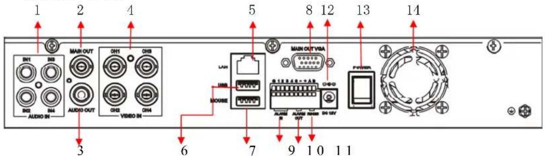
| No. | Icon | No. | |
| 1 4 Audio Input 8 VGA Output | |||
| 2 Main out 9 Alarm In | |||
| 3 | Audio out | 10 | Alarm Out |
| 4 | 4 CHs Video Input | 11 | RS-485 Interface |
| 5 | LAN Interface | 12 | Power Supply |
| 6 | USB Port | 13 | Power Switch |
| 7 | Mouse Interface | 14 | Fan--Optional |
D1 8/16 CH (2U)
Icon

| No. | Icon | No. | Icon |
| 1 CVBS | output 10 CVBS Input | ||
| 2 SPOT | output 11 Video Loop(9-16CH) | ||
| 3 Audio | output 12 LAN Interface | ||
| 4 | Line in | 13 | Alarm Out |
| 5 | Video loop (1-8CH) | 14 | Alarm In |
| 6 | Audio input | 15 | Power Switch |
| 7 MIC input/output | 16 RS-485 Interface | ||
| 8 | VGA Output | 17 Fan | |
| 9 | HDMI Output | 18 Power supply | |
D1 16 CH (1U)

| No. | Icon | No. | Ie |
| 1 | Audio Input 1-8 & Audio output | 8 | LAN Interface |
| 2 | Audio in 9-16 | 9 | Alarm input (16CHs)/output connector(4 CH) |
| 3 | CVBS output | 10 | Power supply |
| 4 | SPOT output | 11 | Video Input |
| 5 | VGA Output | 12 | Power Switch |
| 6 | HDMI Output | 13 | Ground |
| 7 | USB Port |
CIF 8 CH

| No. | Icon | No | Icon |
| 1 | Audio input connector 7 | Mouse connector | |
| 2 | Video output connector | 8 | VGA connector--- (optional) |
| 3 | Audio output connector | 9 | Alarm input(4 channel)/output connector( 1 channel) |
| 4 | Video input connector 10 | Power input socket(12V DC) | |
| 5 | Ethernet connector | 11 | Fan--- (optional) |
| 6 | USB connector | ||
CIF 16 CH

1. Audio Input Connector (CH1--8) & Audio out
8 channels audio input, for connecting audio signal (DB9).
1 channel audio output, for connecting speakers.
2. Video Input Connectors (Video IN 1-16)
16 channels video input, for connecting analog video signal input, BNC (1Vp-p, 75Ω)
3. Video Output Connector
Video output for connecting monitor or TV, BNC (1Vp-p, 75Ω).
4. Ethernet Connector
RJ-45 10/100 Base-T Ethernet network
5. ESATA
Connect with high speed HDD.
6. Power Switch.
7. Alarm Input/Output connector (Alarm IN: 4 CH, Alarm Out: 1 CH)
For connecting to external sensor device
Each alarm has one input pin on the Terminal Block of the rear panel.
Connect positive (1-4) output pins of the device to the input slots (Alarm In) on the DVR terminal block.
Connect ground output pins of the device to the DVR Ground slots (G). Multiple devices can be connected to one ground slot.
Port functions:
Pin 1-G: Sensor 1 input;
Pin 2-G: Sensor 2 input;
Pin 3-G: Sensor 3 input;
Pin 4-G: Sensor 4 input;
Pin NO-COM: Alarm Output (N.O);
Pin A、Pin B: RS-485A、RS-485B;
Alarm Output Connectors (pin

NO-COM) ---- (optional)
For connecting to external alarm device
RS-485 Connector (pin A-B) ---- (optional)
For connecting PTZ camera control
8. MIC
9. USB connectors
Use these USB ports to connect the mouse and backup devices (flash drive, DVD recorder)
10. VGA Connector---- (optional)
For connecting VGA/LCD monitor
11. Power Input Socket (12V DC)
3.3 Remote Control
In device operation, the enter key on the remote control or the front panel has the same function as a mouse left click. The IR Range of the remote control is up to 32FT (10 meters). The buttons on the remote control correspond 1 on 1 with the buttons on the front panel.
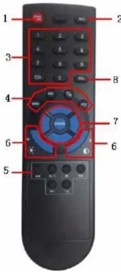
| No. | Name Description | ||
| 1 | Alarm reset | Clears the alarm input or alarm output status. | |
| 2 | REC | Recording control. Has the same function as the “REC” button on the device’s front panel. | |
| 3 | Numeric buttons | Input numbers or select to change relevant channels. | |
| 4 | Functional Buttons |  | Enter the main menu. |
 | Switch from the single window view mode to multiple split view mode | ||
 | Return to upper menu, same as the button on the front panel | ||
 | Enable PTZ control, same as the “PTZ” button on the front panel | ||
| 5 | Playback Control |  | Play in slow mode / rewind Iris- |
 | Play/Pause Iris+ | ||
 | Stop | ||
 | Change speed for play back or fast forward Zoom+ | ||
| [KBYK] | Go to next frame Focus+ | ||
| FN | Function, access to auxiliary settings. | ||
| 6 | Picture Adjustment Parameters |  , - , - | Buttons for zoom in or zoom out |
 , - , - | Buttons for adjusting focus | ||
| 7 | Arrow Buttons | Similar to the functions of arrow buttons on the front panel | |
| 8 | DEL | DELETE button | |
3.4 Mouse Control
You can use a mouse to operate the DVR as well. The mouse operates just like a mouse on a Windows PC. Please connect the mouse to the USB connector in the back panel and please note that you can hot-plug the mouse.
| Left click mouse | System pops up password input dialogue box if you have not logged in.In real-time monitor mode, you can go to the main menu. |
| When you have selected one menu item, left click mouse to view menu content. | |
| Implement the control operation. | |
| Modify checkbox or motion detection status. | |
| Click combo box to pop up drop down list. | |
In input box, you can select input methods. Left click the corresponding button on the panel you can input numeral/English character (small/capitalized) here.← stands for backspace button.stands for space button.In English input mode:_stands for input a backspace icon and ← stands for deleting the previous character.In numeral input mode:_stands for clear and ← stands for deleting the previous numeral.When input special sign, you can click corresponding number in the front panel to input. For example, click number 1 you can input“/” “/”, or you can click the number in the on-screen keyboard directly_ number in the on-screen keyboard directly_ | |
| Double left click mouse | Implement special control operation such as double click one item in the file list to playback the video. |
| In multiple-window mode, double left click one channel to view in full-window.Double left click current video again to go back to previous multiple-window mode. | |
| Right click mouse | In real-time monitor mode, Right-click pops up shortcut menu: one-window, four-window, nine-window and sixteen-window, Pan/Tilt/Zoom, color setting, search, record, alarm input, alarm output, and main menu.Among which, Pan/Tilt/Zoom and color setting applies for current selected channel.If you are in multiple-window mode, system automatically switches to the corresponding channel. |
| Exit current menu without saving the modification. | |
| Press middle button (scroll) | In numeral input box: Increase or decrease numeral value. |
| Switch the items in the check box. | |
| Page up or page down | |
| Move mouse | Select current control or move control |
| Drag mouse | Select motion detection zone |
| Select privacy mask zone. |
3.5 Hardware Installation
It is recommended that the installations described below are carried out by qualified personnel.
3.5.1 Basic Connections
■ Cameras
Connect each of the cameras' outputs to the video input socket in the rear panel of the DVR using appropriate cables. The video input interface is a standard BNC connector, 1Vp-p, 75 Ω. Please keep the video signal cable away from strong electromagnetic and electric interference.
■ Audio Connection
The audio input interface is a standard BNC socket.
Please keep the audio signal cable away from strong electromagnetic and electric interference.
■ Monitor
Connect the main output connector to a monitor or a TV screen. Use a BNC-to-RCA converter, if needed, to work with the Audio/Video RCA cable.
Power
Please use the 220V AC supplied for connecting your DVR device with the power source.
■ Alarm Input / Output----(optional)
Connect Alarm In 1-16 to N. O. (Normally Open) or N.C. (Normally Closed) alarm connectors and one Ground connection. Connect Alarm Out to the corresponding connections and Ground accordingly.
For detailed description please see Section 5.3.4 Alarm Input.
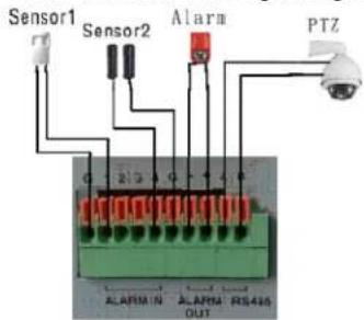
D1/CIF 4/8CH

D1 16CH

CIF 16CH
Ethernet
For remote access to the video images from your cameras via LAN or the Internet, please connect the standard RJ-45 twisted-pair Ethernet cable to the
Ethernet connector.
USB
For connecting the mouse, USB flash drive, USB portable HDD, USB portable DVD Recorder. The USB mouse is hot pluggable.

NOTE: The device only supports FAT32 file system on the USB devices.
3.5.2 Installing Hard Disk Drive
DVR needs install of HDD first, we recommend high-speed HDD 7200rpm or higher, and the SATA cable included in package. The HDD must be formatted before recording.
We take the 16CH mode as the example:
- Loosen the screws on the top cover
- Open the cover
- Put the HDD on the HDD bracket

natural_image
Close-up of a gloved hand installing or adjusting a perforated metal component with black holes, partially open to clean the circuit board (no visible text or symbols)- Use provided HDD screws; install the HDD on the bracket

natural_image
Close-up of hands installing a screwdriver on an open electronic device with visible circuitry and wiring (no text or symbols)- Fix the HDD bracket on the DVR HDD bracket
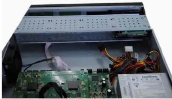
natural_image
Interior view of an electronic device showing a circuit board, power connectors, and a server rack (no visible text or symbols)- Use SATA cable to connect the DVR main board SATA ports,
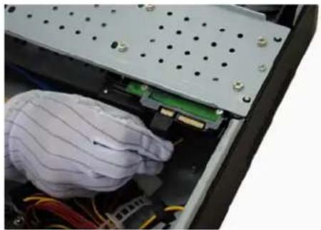
natural_image
Close-up of a gloved hand inserting electronic components into a computer chassis (no visible text or symbols)
natural_image
Close-up of a gloved hand inserting a cable into a green circuit board with visible wiring (no text or symbols)- Then connect power cord to the HDD

natural_image
Close-up of a computer motherboard with visible wiring and a partially open socket (no text or symbols)- Close the DVR enclosure and screw firmly
3.5.3 PTZ Control Connections---- (optional)
Connect the PTZ control jacks to the corresponding RS485 A and B interfaces on the rear panel.
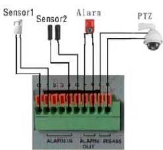
D1/CIF 4/8CH
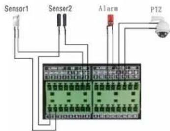
D1 16CH
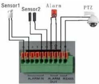
CIF 16CH

For detailed description of PTZ protocols, baud rates and IDs please refer to the setup section in the PTZ manual.
4. Getting Started and the Main Screen
4.1 The Main Screen
Switch on your DVR and wait for the system program to load. When you enter the system you can see the main screen. The standard layout is eight windows (or sixteen windows, depending on your device) evenly distributed over the screen. From the main screen you can access menu options and switch among channel views, displaying either all channel feeds simultaneously or bringing forth a full-screen view of a selected channel.
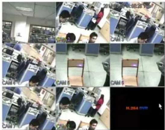
After starting up, videos will be outputted on both VGA (HDMI) and TV, but the menu will only be displayed on one side. There are two ways to switch menu between VGA and TV: 1) Main Menu>>Setting>>General>>Display Mode >> HDMI/VGA/TV; 2) Press button “MULTI”, then “ENTER” on front panel to switch output.
Note; After installing a HDD for the first time, you should format it: Main Menu >> Advanced >> HDD Manage>>Format
4.1.1 Displaying a Single Channel
In the multiple screen view, you can make a particular window active by left-clicking on it once with a mouse. If an audio output device is connected to this channel, you can monitor both audio and video feeds.
To enter a single channel view you can press the corresponding numerical buttons on the remote (channel number is displayed in the bottom left corner of each window); alternatively you can do so by left double-clicking on the desired window, or by choosing "View 1" on the shortcut menu.
In order to return to the multi-screen view you could either double-click on the screen again or press the “Multi” button either on the remote control or the front panel.
You can choose to display the shortcut menu by single right-clicking on the screen.
4.1.2 Login System
In Live view, press the button "MENU" once or click "Main Menu" on shortcut menu
to display the main menu. A login window will appear.
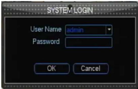
You can login from the LOGIN window as shown above. Select user name and fill in user password (You can select username by pressing control button[▲] , [▼]ve cursor to password edit bar by pressing control button ▶ and switch input method by pressing "REC" button.). You can access the main menu by pressing [OK] if the password is enabled.
The default password for Admin is "888888". For your convenience and system safety, you can change password of admin and add other users.
4.1.3 Shortcut menu
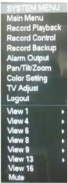
Right click on your mouse to display the shortcut menu shown on right hand.
【Main Menu】:Enters system configuration menu
【Record Playback】:Search recorded files and playback
【Record Control】: Set recording modes
【Record Backup】: Backup recorded files
【Alarm Output】: Clear alarm or set alarm type
【Pan Tilt Zoom】:Control PTZ (Pan Tilt Zoom), set preset, pattern, border, and tour
【Color Setting】: Set color for each channel
【TV Adjust】:Screen layout adjustment
【Logout】:Logout menu user
【View 1】:View one channel in full screen mode
【View 4】:View four channels in full screen mode
【View 6】: View six channels in full screen mode
【View 9】: View nine channels in full screen mode
【View 13】: View thirteen channels in full screen mode
【View 16】: View sixteen channels in full screen mode
【Mute】: Turn sound on or off
See the following subsections for a detailed description of each of these functionalities.
4.2 Shortcut Menu Options
4.2.1 Main Menu
Pressing this button will bring up a menu for setting up all system configurations. You can adjust settings such as Record, Alarm, Setting, Advanced and Information. Please refer to Section 5. DVR Settings for the detailed description of these settings.

4.2.2 Record Playback
To play the recorded video, press the Record playback button on the shortcut menu to enter video playback interface.
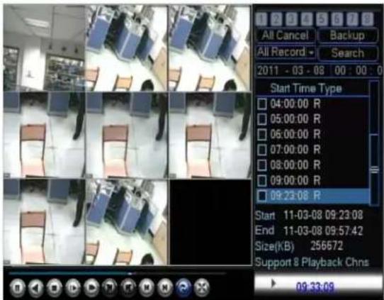
You should select channels you want to search and click the Search button.
There will be a notes list on the right panel. You can double click any recording on the list for playback.
In order to playback a certain video feed from a particular camera, you first need to indicate what time and which camera you wish to receive this information from. Then
click Search
to search the files.
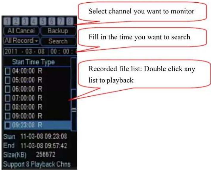
After searching, there will be a list of recorded files, double click any item on the list to playback.
Playback Control
In the playback mode you can see the playback control panel as well as the date and time of the played file.
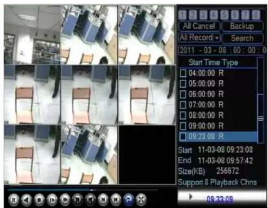
In the playback view, you can drag an area with your mouse then click this area to zoom out.
Options for the playback control panel are described below:

: Play/Pause
Rewind/Pause
Stop
Slow forward.
Fast forward.
: Repeat playback.
Pre-frame (This button will be able when the file is paused).
: Next frame (This button will be able when the file is paused).
M: Pre-file. Click this button to playback pre-file.
M: Next file. Click this button to playback next file.
: Display single-channel in full screen mode.
You can right click on your mouse to exit playback file and click again to exit playback interface.
4.2.3 Video Backup
There are two ways to backup recorded files:
Method 1: Backup recording files according to time segment.
- Insert your USB disk or USB DVD burner into USB port
- Look over your device: Main Menu>>Record>>Record Backup. In this interface, the user can get the available free space and total space (If you can not see USB disk in the list, you can click button "Detect" to detect device).
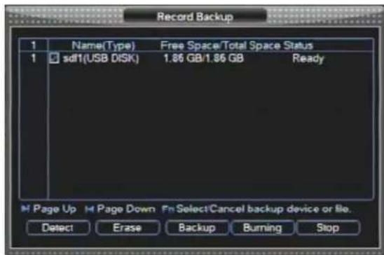
- Click "Backup" to enter into backup interface. Click "Erase" to delete data in your USB disk
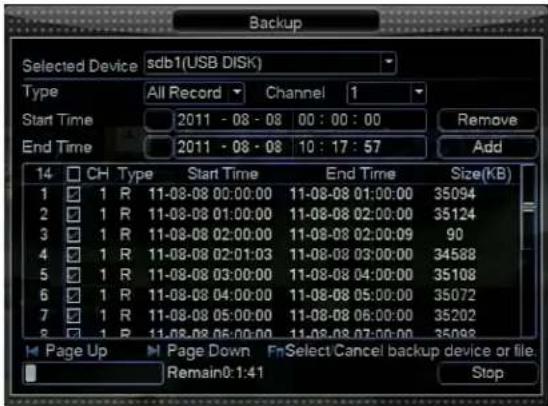
-
In backup interface, user can select device, select recording type, channel and time period which you want to backup, then click "Add" to add files.
-
Click "Start" to start backup files
Method 2: Backup recording files according to detail files
To back up the recorded footage, you first need to indicate which cameras and time interval you want to save to an external source.
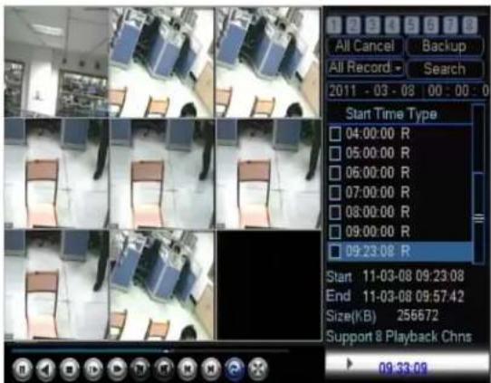
After searching recorded files; you can choose files check marked “☐” on right panel and click “Backup” to enter backup interface.

After that click the START button, it will begin backup this file. A "Backup" dialog window will appear. If the system cannot recognize the connected devices or none are connected, you will see a warning message "You have not selected a device!"
The system will automatically detect all available backup devices and display them in the Backup Device field (positioning the mouse over this field or entering it with the help of the arrow buttons will allow you to view the available choices.).
Currently you can connect such external media as USB flash drives, portable USB HDDs and USB DVD recorders.

The system only supports the FAT32 file system for USB flash drives and HDDs
Playing backed up video on your PC
The backup file will be in DAV format and it can be played by special player (This player will be provided in CD disk).
4.2.4 Record Control
Press the Record Control button on the shortcut menu, following dialog box will appear to record control. You can set the record mode for each channel: schedule recording, manual recording, or stop recording. In schedule record mode, videos will be recorded according to your setting in section 5.2.1 SCHEDULE.
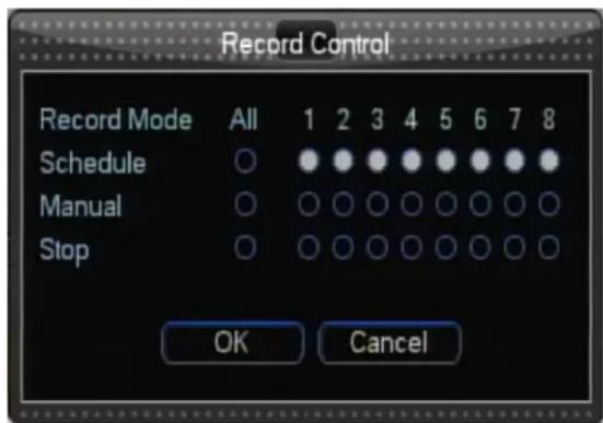
Recording status is displayed in the bottom left corner of the respective screen.
For a detailed description of the Scheduled feature see Section 5.2 Record Settings. Description of the manual recording function follows.
In order to record a video/audio feed, select the REC button in the Tool Menu to enter the Record Control interface and select “Manual” to start manual recording. Alternatively you can use the REC button on the remote or the front panel. If you choose “Stop” it will stop recording. Press OK to confirm, or press Cancel to undo your choice.
4.2.5 Alarm Output
Click the Alarm Output option on the shortcut menu to display alarm output interface.

【Alarm Type】; There are two types for you to select: Schedule and Manual
【Schedule】; Set Alarm Output when alarm is triggered. Select all for all the channels, "1" for the first channel, "2" for the second channel, "3" for the third channel, and "4" for the fourth channel.
【Manual】; Set alarm output all the time. You can set every channel respectively
【Stop】; Close alarm output
【Status】; Current device alarm output status
4.2.6 PTZ Control
You can use this function if your DVR is connected to a PTZ camera (Pan-Tilt-Zoom). Pressing the button Pan Tilt Zoom on the shortcut menu will bring the corresponding video feed into the single-screen mode. In the screen you will see the special PTZ menu.

- Directional buttons: Control the direction of the PTZ cruise. Please refer to your PTZ manual for details of PTZ scanning mode.
- Press the “Next Page” button to enter the advanced function; it will be introduced in following.
- Speed: Sets the turning speed of PTZ camera. Adjust numbers for adjusting this setting.
- Zoom: Click to zoom in / zoom out
- Focus: Click to focus-in and focus-out (this function is disabled for cameras with automatic focus).
- Iris: Click to make the image brighter or darker (this function is disabled for cameras with automatic iris adjustment).
- Click the "SET" button to enter the setting interface; you can set preset, tour, pattern, and border.
If you click "Next Page", you will enter interface as following:

- NO.: Input number to use
- Pattern: Start up pattern
- Auto Scan: Start up auto scan
- Flip: Turn over image
- Preset: Call on preset point
- Tour: Start up tour
- Auto pan: Circumrotate PTZ flatly
- Reset: Reset parameter of PTZ
- Auxiliary Operation: Click "ON" to open and "OFF" to close. Different functions respond to different protocols. The auxiliaries include light, wiper, power, etc. Please refer to your PTZ manual for details.
- Auxiliary Number: It should be used with Auxiliary Operation
4.2.7 Color Setting
Press "Color Setting" on the shortcut menu to enter color setting interface.

User can set two periods to set hue, brightness, contrast and saturation for each channel respectively.
4.2.8 TV Adjustment
By pressing the TV Adjust button on the shortcut menu, you will bring up the TV Adjust screen.
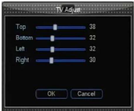
You can move the entire video screen up, down, left and right using this option.
4.2.9 Logout
Press the Logout button on the shortcut menu to logout menu user.
4.2.10 Screen View Modes
View1, View4, View6, View8, View9, View16
Allows you to switch between single/multiple screen views (1-screen, 4-screen, 6-screen, 8-screen, 9-screen modes or 16-screen modes).
OK confirm the adjusted position
Cancel cancel the introduced position changes
4.3 Channel Status Display
The top right corner of each channel image features the following status icons:
This icon indicates that the channel has detected motion in the motion detection mode.

This icon indicates that the channel is currently recording.
5. DVR Settings
5.1 Main Menu
| Main Menu | Sub Menu Function | |
| Record | Schedule | Time setting for common record, motion detection, and external alarm.Time operated setting per; day per week (Period time for record, receive external alarm signal, and motion detection) |
Search | Record inquiry and playback are sorted by video type (All / Alarm/ Motion detection/ All alarm), channels, and time. The result will be displayed in a file list; select the file to play.R- Regular recording file A – Alarming recoding fileM – Motion detection file H – Manual | |
Backup | Record backup operation and setting | |
| Alarm | Motion Detection | Includes channel, enable/off, sensitive, detection zone, arming time, output time delay, alarm linkage, PTZ linkage, pre-recording, patrol setting etc. You may copy & paste for same settings. |
Camera Masking | Include channel, enable/off, sensitive, arming time, output time delay, alarm linkage, PTZ linkage, pre-recording, patrol setting etc. You may copy & paste for same settings | |
| Video Lost Include channel, enable/off, arming time, output time delay, alarm linkage, PTZ linkage, pre-recording, patrol setting etc. You may copy & paste for same settings | ||
 | ||
Alarm Input | Include channel, enable/off, alarm input type, arming time, output time delay, alarm linkage, PTZ linkage, pre-recording, patrol setting etc. You may copy & paste for same settings | |
Alarm Output | Alarm Mode, setting, on/off and status | |
Abnormity | Abnormity setting, on/off and linkage action (Alarm output) | |
| Setting | General | Setting of system time, time format, language, recording in HDD, series number, video system, video output format, stand-by time, etc. |
Encode | Setting of audio & video encode mode, frame rate, quality, etc. | |
Network | Setting of network address, video transmission protocols, DHCP, etc. | |
Display | Setting channel name, front output, coding output, masking, etc. | |
Account | User group and account settings | |
PTZ | PTZ control protocols and bit rate | |
RS232 | Setting of series port and bit rate | |
Tour | Setting preview, tour time, etc. | |
| Advanced | HDDManagement | HDD management, delete data and etc.Note: System will restart after setting HDD |
 | |||
USB Upgrade | Upgrade system through USB disk | ||
Configuration | Export parameters to USB disk or import parameters from USB disk | ||
Maintenance | Set time to auto-reboot system and select modes to auto-delete old files | ||
Default | Reset some parameters to factory default | ||
Shut Down | To Logout system, shut down machine, restart system or switch users | ||
| Information | HDD Information | SATA interface status, capacity for each HDD and total, remaining capacity, video start/stop time, etc. Type: read-write disk, read-only disk, redundancy disk etc. | |
BPS | To view bit rate of each channel and occupied HDD capacity per hour. | ||
Log | Display important event log and designate needed log. | ||
Version | Display system hardware, software version and release date, etc. | ||
5.1.1 Menu Options
In order to modify/adjust system configuration, you need to enter the System Menu by pressing the Main Menu button on the shortcut Menu.

You will see the dialog window with settings for all the systems and options available on your DVR. The settings are subdivided into 5 subsections, each with its own tab: Record, Alarm, Setting, Advanced and Information. Below is the detailed description of these settings.
In system configuration, you can use the arrows “▲ and ▼” to switch between tabs. Use the buttons ◀ and ▶” to select the Sub-menu. Right-clicking on your mouse will exit current menu.
5.2 Record Settings

User can set the recording schedule, search recording files, and back up files.
5.2.1 Schedule
When the system boots up, it is in the default 24-hour regular mode. You can set
record type and time in the Schedule interface: Main Menu>> Record>> Schedule.
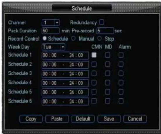
【Channel】 Select the channel number first. You can select "all" if you want the same setting for all channels.
【Redundancy】System supports the Redundancy backup function. You can highlight the Redundancy button to activate this function. NOTE; before you enable this function, at least one HDD has to be set as redundant. (Main Menu >>Advanced>>HDD Management) --- (optional)
【Pack Duration】 Set pack duration for video file
【Pre-record】 records the video prior to motion detection
【Record control】 single option, the “●” symbol represents what is selected. The 3 options are: “schedule”, “manual”, and “stop”.
【Week day】 There are eight options total. Ranges from Sunday to Saturday and Everyday (all).
【Time period】Means current channel is recording in this period. Recording modes include: Common recording, Motion triggered recording, and Alarm triggered recording. It can be set to single or multiple choices. 6 time periods to set.
Also allows you to copy one channel's setup to another. After setting in Channel 1, you can click Copy and Paste onto channel 2.
You can finish setting for one channel and then click save button or you can finish all setup and then click save button to memorize all the settings.
5.2.2 Search
You can search recorded files in the video playback interface: Main Menu
Record>> Search. The interface is the same as the Record playback interface; refer to section 4.2.2 Record Playback.
5.2.3 Record Backup
You can backup recorded files in the Video backup interface: Main Menu>> Record>>Record Backup. The interface is the same as the Video backup interface. Refer to section 4.2.3 Video backup.
5.3 Alarm Setting
The next menu tab in the Main Menu is Alarm. Under this tab the administrator can define how the DVR will respond to various alarms from the motion detection, camera masking, video lost, alarm input, alarm output and abnormality. Following is the description of the possible options.

5.3.1 Motion Detection
By analyzing video, when the system detects a sensitive moving signal, it will start the motion detection alarm.
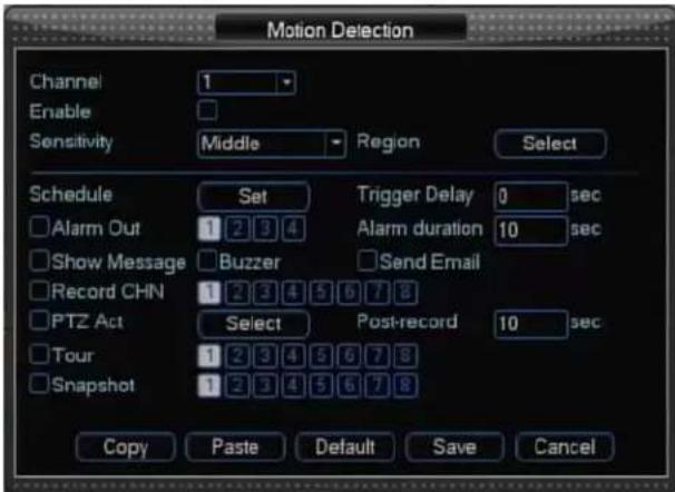
Operation method:
【Channel】select the channel you want to implement motion detection on.
【Enable】enable or disable function.
【Sensitivity】System supports 6 levels.
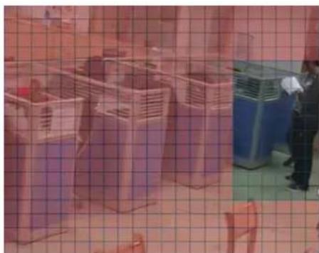
【Region】 Can be set up to 396 (22*18) zones. The transparency is an open zone; the pink is the motion detection zone.
natural_image
Interior view of a warehouse or storage facility with large metal crates and a worker in the background (no visible text or symbols)【Schedule】 Click set button, you can see an interface as shown as below. Here you will set your own setup for business day and non-business day.

【Trigger Delay】System auto delays during specified time periods. The value ranges
from 10 - 300 (second units)
【Alarm output】 when alarm occurs, system enables peripheral alarm devices
【Alarm duration】Alarm output: Set output time for alarm when motion detection is complete. The value ranges from 10-300 (second units)
【Buzzer】 Default is "off"
【Send email】System can send out emails to alert you when an alarm occurs.
【Channel】Select the channel to activate recording function once alarm occurred. Make sure you have set MD record in the encode interface (Main Menu >>Record>>Schedule)
【PTZ activation】 Allows you to set PTZ movement when alarm occurs. Go to preset, tour &pattern when there is an alarm. Click the “OK” button to save changes.

【Tour】 Here you can enable tour the function when alarm occurs. It is a one-window tour.
【Snapshot】Enable or disable snapshot.--- (Optional)
5.3.2 Camera Masking
By analyzing video, when the system detects camera masking, it will start camera the masking alarm.
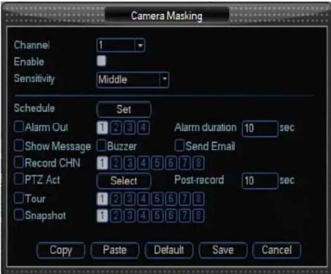
When someone viciously masks lens, the system can alert you to guarantee video continuity. You can select Alarm output, PTZ Linkage.
Operation method:
【Channel】select the channel to record when camera mask occurred.
【Enable】Enables function switch
【Sensitivity】there are six levels.
【Schedule】Click the set button, you can see an interface is shown as below. Here you can set business day and non-business day. You can set up to six time periods, but they cannot be repeated. The linear graphics show the periods. You can copy the setting to other days
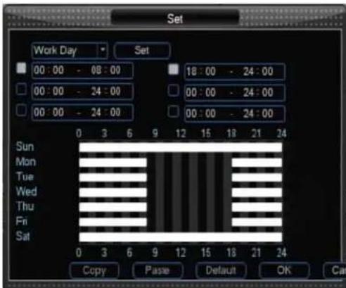
【Alarm output】: when camera masking occurs, system enables peripheral alarm devices
【Alarm duration】 During camera masking, the system auto delays detecting for a specified time. The value ranges from 10 - 300 (second units)
【Buzzer】Default is "Off"
【Send email】System can send out emails to alert you when alarm occurs.
【Channel】Select the channel to activate recording once alarm occurs. Make sure you have set alarm record in the Encode interface (Main menu->Record->Schedule)
【PTZ activation】Set PTZ movement when alarm occurs. Go to preset, tour, &pattern when there is an alarm. Click the “select” button,
【Tour】Enable tour function when alarm occurs. It is a one-window tour.
【Snapshot】Enable or disable snapshot.--- (optional)
5.3.3 Video Lost
By analyzing video, when system detects video lost, it will start video lost alarm.
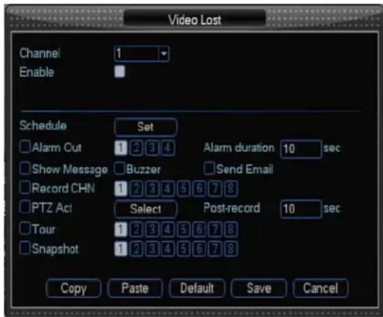
Operation method:
【Channel】 Select the channel you want to enable lens shading alarm.
【Enable】Enable function switch
【Period】 Click “Set” button, you can see an interface as displayed below. Here you can select business day and non-business day. You can set up to six time periods, but they cannot be repeated. The linear graphics show the period,
you can copy the setting to other days.
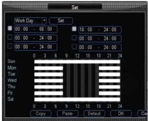
【Alarm output】: When video lost occurs, system enables peripheral alarm devices
【Alarm duration】: When video lost occurs, system auto delays detecting for a specified time. The value ranges from 10-300 (second units).
【Buzzer】: Default is "Off"
【Send email】: System can send out emails to alert you when alarm occurs.
【Channel】: Select the channel to activate recording once alarm occurs. Make sure you have set alarm record in the encode interface (Main menu->Record->Schedule)
【PTZ activation】: Set PTZ movement when alarm occurs. Go to preset, tour & pattern when there is an alarm.
【Tour】: Enable tour function when alarm occurs. It is a one-window tour.
【Snapshot】: Enable or disable snapshot.--- (optional)
5.3.4 Alarm Input
Setting at Main menu>>alarm>>alarm input.
According to the introduction of 3.5.1 Basic Connection, make sure you have properly connected alarm devices such as Alarm and Lighter.
User can save each channel configuration or save once until all channels are set.
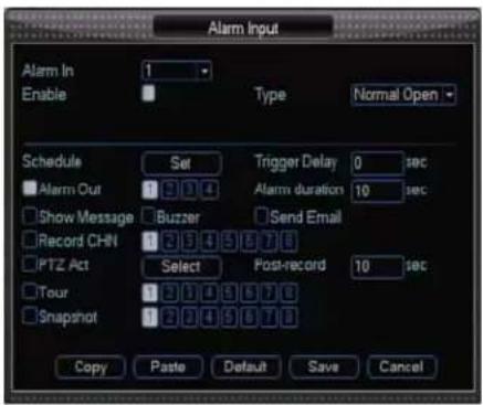
【Alarm input】Select alarm channel number
【Enable】Enable function switch
【Type】 Normal open or Normal close (According to your alarm device).
【Schedule】Set for business day and non-business day. You can set up to six time periods, but they cannot be repeated. The linear graphics show the periods. You can copy the settings to other days.
【Alarm out】Activate peripheral alarm device when motion detection occurs.
【Trigger Delay】Set proper delay duration. Value ranges from 0 to 600 seconds.
【Buzzer】Default is "off"
【Send email】System can send out emails to alert you when alarm occurs.
【Record channel】Select proper channel to record alarm video (Multiple choices)
【PTZ activation】Set PTZ movement when alarm occurs. Go to preset, tour & pattern when there is an alarm.
【Post-record】 It sets the record time of duration before alarm is activated.
【Tour】Allows you to enable tour function when alarm occurs. A one-window tour
【Snapshot】System can capture the selected channel.--- (optional)
5.3.5 Alarm Output
You can set alarm type and get information about alarm output in the alarm output interface: Main Menu>>Alarm>> Alarm Output. The interface is the same as section 4.2.5 Alarm Output.
5.3.6 Abnormity
You can set alarm type when abnormality events had triggered in this interface: Main Menu>> Alarm>> Abnormity.
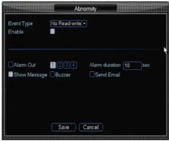
【Event type】 no disk space, hard disk error, Not enough space, network failure, IP address conflict.
【No disk space】 DVR does not connect to the disk or hardware if error.
【Disk error】The system can not recognize because of disk error
【Not enough space】 Not enough space for the disk (the percentage of free space will be shown)
【Network failure】The network connection disrupted or network connection error
【IP conflict】 The IP address of disk recorder network is fixed, the conflict will occur the same IP address is set on the internet.
【Enable】Enable function switch; reverse means “on”.
【Alarm output】 When exception occurs, system enables peripheral alarm devices
【Alarm duration】 System auto delays for a specified time. The value ranges from 10-300 (second units)
【Buzzer】 Default is "off"
【Send email】System can send out emails to alert you when alarm occurs.
5.4 System Settings

5.4.1 General Setting
You can set system time, date format, auto logout time, date separator, DST, time format, audio set, language, HDD full, DVR number, video standard, display mode and resolution: Main Menu>> Setting>>General.
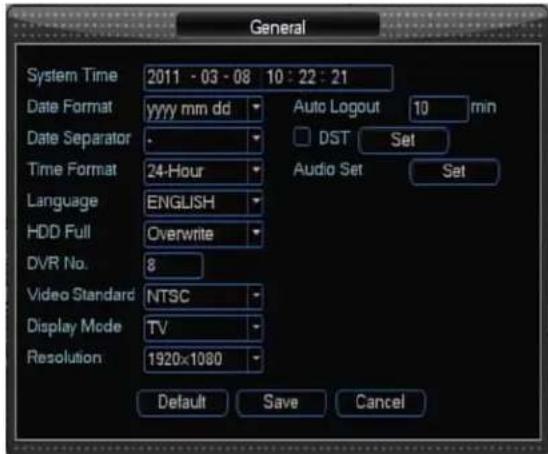
【System Time】 Adjust the current date and time of the DVR.
【Date Format】 Toggle data format among "yyyymmdd", "ddmmyyyy" and "mmddyyyy".
【Auto Logout】Set time for auto logout;
【Date Separator】Select a symbol separator for the date from “.”, “-” and “/”.
【DST】Daylight Saving Time (DST). Click “enable” enable. Click the “Set” button to enter DST setting interface. You can setup the start and end time for DST.
【Time Format】Toggle time format between 12-Hour and 24-Hour This option will take effect after saving and exiting.
【Audio Set】Set audio source and volume for talkback.
【Language】To change language of the DVR menu text and the On-Screen text
【HDD Full】 Select record mode between “Overwrite” and “Stop Record” when HDD is full.
【DVR Number】Set device ID, it will be used for remote keyboard operation.
【Video Standard】 Select of the preferred video standard. Available options are NTSC and PAL.
【Display Mode】Select display position among TV, VGA and HDMI.
Note: User can press "MULTI" or "Enter" to switch display mode.
【Resolution】Select the preferred VGA output resolution. Depending on the model, you can make your choice among: 1024x768, 1280x720, 1280x1024, and 1920x1080.
Note: User can press "MULTI" and "▼" button to switch display mode.
5.4.2 Encode Setting
You can set encode resolution, frame rate, bit rate type, quality, bit rate and iframe interval: Main Menu>> Setting>> Encode

【Channel】 Select channel number
【Compression】H.264
【Resolution】D1, HD1, CIF---Please take the actual machine model as quasi
【Frame rate】 PAL:1-25 f/s, 25 levels optional; NTSC:1-30 f/s, 30 levels optional
【Bit rate】System supports two types: CBR and VBR
【Quality】 There are six levels ranging from 1 to 6. The sixth level has the highest image quality.
【Bit rate】: 768kb/s - 4096kb/s (optional)
【Frame interval】: can set from 1 frame, 2 - 12 optional. Copy the same settings to all channels (optional).
5.4.3 Network Setting
You can configure network parameters in this interface: Main Menu>> Setting>>Network

【IP Address】Your DVR supports several methods of viewing online. No matter which method is used, your DVR must first acquire an IP address, which it does via 2 different methods.
- Automatic acquisition of the IP address by the DHCP client model.
- Manual indication of the IP address by the Static IP model.
This field offers two options: Static IP and DHCP. Toggling these will either make the three fields (IP Address, Subnet Mask and Gateway) changeable (in manual mode) or not (in auto mode); these fields are:.
【Subnet Mask】Obtain information about subnet mask. Subnet mask is a system of interconnections within a communications system that allows the components to communicate directly with each other. The default subnet mask is 255.255.255.0.
【Gateway】You can set gateway according to your net segment.
【TCP Port】It is 34567 by default. When you use your mobile phone to monitor, you should input this port.
【HTTP Port】Used to connect to the DVR web server. By default the port value is 80. You can specify a different port number.
【UDP Port】It is 37778 by default.
【Max Connection】System supports maximal 10 users. 0 means there is no connection
【Transfer Mode】Set transfer mode: latency, self-adaptive, and fluency
【LAN Download】System can process the downloaded data first if you enable this function.
【Advanced Setting】In advanced setting, user can double click any list to set Email, DNS, DDNS, PPPOE, FTP, Online User etc. There will be
introduction of some important functions.
Note: You should enable the relevant function with √ before setup.
【Email】Double clicking E-mail Setting will bring up a dialog window, where you can adjust the necessary settings.
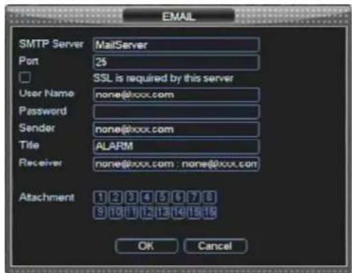
SMTP Server: Input server address and then enable this function.
Port: Default value is 25. You can modify it if necessary.
SSL: Security Socket Layer
User Name: The sender email account user name.
Password: The sender email account password.
Sender: Sender email address.
Title: Input email subject here.
Receiver: Receiver email address.
Note: Please fulfill the postfix of the mail address if it is virtual,(e.g. xxxx@yyyy.com) otherwise it is not allowed. (e.g. xxxx)
【DNS】Domain Name Server. These values depend on your actual account. Please contact your Internet Service Provider for details. User can use a primary DNS address and a secondary DNS address.

【DDNS】In order to connect your DVR to the internet, you may choose to use the services of a Dynamic DNS.

Your DVR comes with several DDNS server names built-in. To be able to use these servers, you need to go to the associated website to register for an account. Once registered, you choose the name of the DDNS Server from the list by pressing the arrow buttons located at both ends of the corresponding field and input the DDNS name, user name, password. Afterward, it should automatically connect.
【PPPOE】These values depend on your actual account, please contact your Internet Service Provider for details. In this interface, you should input username and password, an IP address will appear in this interface.

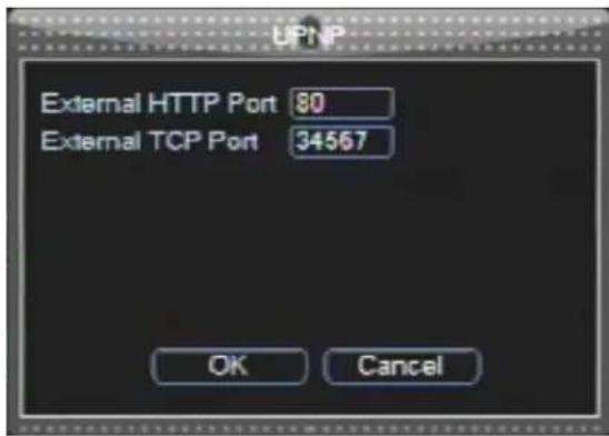
【UPNP】Set external HTTP Port and TCP Port which is mapped in the Internet.
5.4.4 Display Setting
You can configure display parameters in this interface:
Main Menu>> Setting>>Display
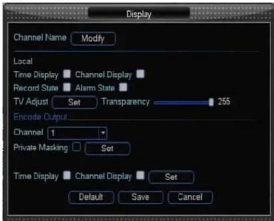
【Channel Name】: Set name for each channel
【Time Display】Show or conceal time on each channel
【Channel Display】Show or conceal channel name.
【Record State】Show or conceal record state.
【Alarm State】Show or conceal alarm state.
【TV Adjust】Move the entire video screen up, down, left and right.
【Transparency】Set transparency for menu display
【Channel】Select channel to set private masking and set position to display time.
【Private Masking】Enable or disable private masking. If private masking was activated, you should select a number to set private masking. You can set four pieces of area covered at most.
【Time Display】Set position for time display.
【Channel Display】Set position for channel name.
5.4.5 Account Setting
You can manage users in this interface: Main Menu>> Setting>> Account

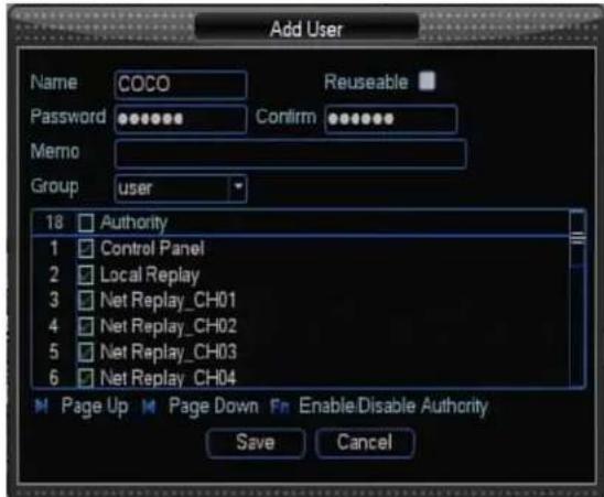
【Modify User】You can modify user's name, memo, group and set permissions. There are 2 default users: “Admin” and “guest”. “Admin” users have administrator right. The default password is “888888” for “Admin” and “123456” for “guest”. “Guest” user only can review Local replay and Net replay, Local preview and Net preview. Reusable function: this function allows multiple users use the same account to login. Once you select the user to a group, the user authority can not surpass this group authority property.
We recommend that normal user's authority lower than other advanced user.

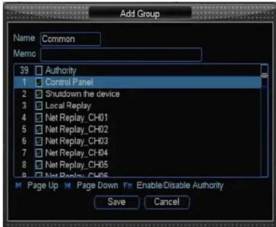
【Modify Group】In this interface, you can edit group name, set memo and set permissions for the group.

【Modify Password】you can select the name you want to change password on. Before set new password, you must input the old password right.

【Add User】You can add new users and set password, group and authority.
【Add Group】You can add new group and set its permission.
【Delete User】Select a user and Click this Delete User to delete it.
5.4.6 PTZ Setting
You can configure PTZ parameters in this interface: Main Menu>> Setting>> PTZ Setting

【Channel】Select the camera (channel) number whose settings you want to modify.
【Protocol】Select the PTZ device protocol. It must be consistent with the protocol of the actual PTZ cameras installed. You can choose between: Pelco-D, Pelco-P, Panasonic, Samsung, SONY...etc. The changes will take effect after you save and exit.
【Address】Select the PTZ address. It must be consistent with the address of the actual PTZ cameras installed. Choose any number from 1 to 255. Please note that this is not the same as the number of the channel to which you hook up the PTZ camera in your DVR system.
【Baud rate】Select the PTZ device baud rate. It must be consistent with the baud rate of the actual PTZ cameras installed. You system supports eight options: 1200, 2400, 4800, 9600, 19200, 38400, 57600, 115200.
【Data Bits】Options include 5, 6, 7 and 8. The default setting for DATA BIT is 8.
【Stop Bits】Options include 1 and 2. The default setting is 1.
【Parity】Options include None, Odd, Even, Mark and Space. Default setting is None.

Note: When making changes to PTZ camera functionality / settings, make sure that these changes are being made to actual PTZ cameras by selecting the correct number in the previous field (Camera Channel).
5.4.7 RS232
There are various devices for you to select. Console is for serial port or min-end platform to upgrade program. Keyboard is for you to control current device.

【Baud rate】You can select proper baud rate.
【Data bit】You can select proper data bit.
【Stop bit】There are three values: 1/2.
【Parity】 there are 4 choices: none/odd/even/blank
【System default】 Console, Baud rate is 115200, data bit is 8 digits, stop bit is 1, and Parity is none.
5.4.8 Tour Setting
In this interface, you can enable or disable Tour; set views for tour.
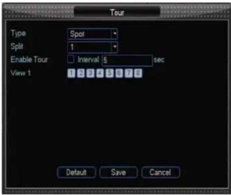
【Type】 Select display mode of tour: General and Spot—Please take the actual machine model as quasi.
【Split】Set tour split mode
【Enable Tour】Enable or disable tour
【Interval】 This refers to sequencing time
【View mode】Select view mode for tour.
5.5 Advanced Setting
Next menu tab in the Main Menu is Advanced Setting. Under this tab user can manage HDD, upgrade system, configure parameters, maintenance system, reset all configurations to factory defaults and shut down system.

5.5.1 HDD Manage
In this interface, you can manage HDD: Main Menu>>Advanced>>HDD Manage

If 2pcs of HDD are installed, they will be displayed as 1-2 in HDD. If selecting the first HDD, it displays current type, total capacity, and status. You can modify HDD attribute, read-only disk, read-write disk, redundancy disk or format all the data in the HDD. After all the setups please click OK button, system goes back to the previous menu
Note: You can set proper mode for each HDD from the dropdown list. When you use redundant backup function, you can set one or more redundant HDD(s).
Note: You need to set at least one read-write disk, otherwise system will not record video.
5.5.2 USB Upgrade
Connect to the USB port on the rear panel with the USB device, which has upgrade file, then select the file to upgrade.

5.5.3 Configuration
In this interface, you can export parameters to your USB disk or import parameters from your USB disk: Main Menu>>Advanced>>Configuration
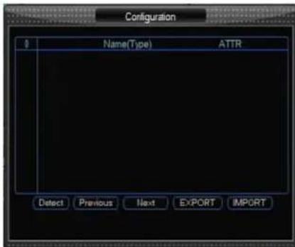
Export: Connect to the USB interface on the rear panel with the USB equipment, set the system output into a file named cfg.coi
Import: Connect to the USB interface on the rear panel with the USB equipment, select setting file to input.
5.5.4 Maintenance
In this interface, you can set a time to auto-reboot system and set time to auto-delete old files: Main Menu>>Advanced>>Maintenance.
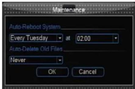
Here you can set Auto-Reboot time and Auto-Delete old files methods.
You can select proper setup from dropdown list. After all the setups please click the save button, system goes back to the previous menu.
5.5.5 Default
In this interface, you can reset some parameter to factory default: Main Menu>>Advanced >> Default.

5.5.6 Shut Down
In this interface, you can logout of system, shut down machine, restart system and switch users: Main Menu>>Advanced >> Shut Down
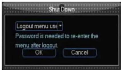
【Logout】: Exit menu. Password need for re-entry to the menu next time.
【Shut down machine】: Logout system turns off power
【Restart system】: System begins rebooting.
【Switch】: Switch users
5.6 Information
Next menu tab in the Main Menu is Information. User can get information about HDD information, BPS, Log and Version: Main Menu>>Information.

5.6.1 HDD Information
In this interface, you can get information about HDD: Main menu>>Information >> HDD Information.

Hard disk type is listed here. Total space, free space, video start time and status.
Note:
Please remove the broken hard disk before you add a new one. Once there is a hard disk confliction, check that hard disk time and system time are the same. Please go to setting then general to modify system time. At last, reboot the system to solve this problem.
If you want to view recording time of some HDD, you can select it, and click "View Recording Time" to get recording Start or end time.
Note: “o” means current HDD is normal. “X” means there is error. “-” means there is no HDD. Please remove the broken hard disk before you add a new one. If disk is damaged, system shows as “?”
After system starts, if there is conflict, it will jump to the HDD information page immediately. User can check the system time and HDD time. If there is a conflict, enter the normal setup to modify system time, or enter advanced HDD management to format HDD, then restart device.
5.6.2 BPS
Here you can view current video data stream (KB/s) and occupied hard disk storage (MB/h)
![BPS Channel Kb/S MB-H Wave 1 1101 426 h [ ] 2 810 334 h [ ] 3 680 282 h [ ] 4 583 280 h [ ] 5 1565 566 h [ ] 6 1545 562 h [ ] 7 664 274 k [ ] 8 755 309 k [ ]](/content/2026/05/987988/images/a85ee1f7e164807a2ac63db02d8665a877234d559d69fd85e72b261d4bcd4878.jpg)
5.6.3 Log
In this interface, you can search log file: Main Menu>>Information >>Log.
![Log Type All Start Time 2011 - 03 - 08 00 : 00 : 00 End Time 2011 - 03 - 09 00 : 00 : 00 1024 Log Time Event 1 11-03-08 09:31:19 Download [ch3 11-03-07 16:00:02] 2 11-03-08 09:31:15 Download [ch3 11-03-07 15:53:28] 3 11-03-08 09:30:54 Download [ch6 11-03-07 16:00:03] 4 11-03-08 09:30:46 Download [ch4 11-03-07 16:00:02] 5 11-03-08 09:30:40 Download [ch8 11-03-07 15:53:58] 6 11-03-08 09:30:36 Download [ch8 11-03-07 15:58:53] 7 11-03-08 09:30:32 Download [ch8 11-03-07 15:53:49] 8 11-03-08 09:30:25 Download [ch6 11-03-07 15:53:46] Page Up Page Down Clear](/content/2026/05/987988/images/eebc46a83b887c11cde07c86b9d175e7f3ea8b9008d849734669eb79bb8aee1c.jpg)
Here is for you to view system log file. System lists the following information.
Log types include system operation, configuration operation, data management, alarm event, record operation, log clear and etc.
Select start time and end time, then click search button. You can view the log files. Please page up/down button to view if there are more than ten files.
5.6.4 Version
In this interface, you can get information about channels, alarm in, alarm out, system version and release date: Main Menu>>Information >>Version

6. Web Browser Operation
Install the software through the IE browser of OS to operate the network remotely and conveniently. DVR supports C/S, B/S, and access in LAN and WAN. It also supports IP and domain name visiting.
6.1 Software Environment
Hardware
Recommended Hardware requirement
- CPU : Pentium 2.8G or above (Dual core)
- Memory : 2G or above
- HDD: 7200 SATA 32M 500G or above
- Display: Video card with YUV output, 64M video memory
- Ethernet : 1000M
Software
- Windows XP
WindowsVista/winodws7 - DirectX 9.0c (above)
RESTRICTION CONDITION :
To ensure PC's stable visiting of DVR, we recommend Windows XP or Win7.
6.2 Network Security Setting
Prior to control installation, please program the network security level by using the following operations:
(1) Open the IE browser and click [Tools→ Internet Options].
(2) Choose the "Security" label in the dialogue box.

(3) Click "Customization level" to enter into the security setting.

Set the ActiveX control and pluggable unit. Select the following options
√ ActiveX control auto-prompting
√ Run the script of the ActiveX control which is marked to be that can safely implement the script.
√ Implement initialization and run the script of the ActiveX control which is not marked to be that can safely implement the script.
√ Binary system and the script behavior
√ Download the unsigned ActiveX control
√ Download the signed ActiveX control
√ Perform the ActiveX control and pluggable unit
It's extremely importation to "enable" the items above.
Prompt: Before control installation, please turn off the fire wall and the anti-virus software.
6.3 Connection Setting
The remote access for the hard disk recording machine should be carried out through the network. In the local area network connection, the IP address of the client-side computer must be in the same network section with that of the hard disk recording machine. While in the wide area network connection, just ensure that two sides can visit the public network, and connect through the IP address or the dynamic domain name. The following will mainly focus on the connecting and setting method for the local area network.
Step 1: Right click on “Network neighborhood” and click “Attribute” in the ejected menu to open the “Network connection”.
Step 2: Double click to open "Local connection".
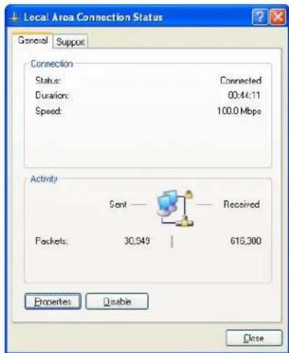
Step 3: Click "Attribute".

Step 4: Double click "Internet protocol (TCP/IP)".
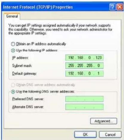
Step 5: Examine the IP address, subnet mask, and default gateway on the PC.
Step 6: Set the corresponding IP address, subnet mask, and default gateway on the DVR (refer to 5.5.5 Network Setup). If the subnet mask and default gateway on DVR are the same with those of the PC, then the IP address must be in the same network section but cannot be the same with the used one. Otherwise, it will cause IP address conflicts. Take the figure above as an example, the IP address should be: 192.168.0.X, wherein, X cannot be 40 or 1 (including other IP addresses currently being used), and cannot surpass 255, the subnet mask is 255.255.255.0, and the gateway is 192.168.0.1.
6.4 Control Download and Installation
After finishing the aforementioned settings, open the IE browser, input http://192.168.0.X (192.168.0.X is the setting IP address of the DVR) and confirm. If the http port of DVR setting has been changed (not 80); you must add colon + port number (assume that the current port number is P), like http://192.168.0.X:P, for correct visit. Then, the network will download and install the control automatically.
After connecting to the internet, IE will automatically download the file to PC as follows.
The system will automatically enter GUI as follows.

Fill in your username, password and select English to enter the system. The password is the same as the one set in DVR.
USER Name: Input user name. The administrator has all authorities, but common user has been limited authorities by administrator.
PASSWORD: The password is the same as the password of Device.
Language: Select language.
If you checked the "Save Password" It will save password automatically.
Note: If you connect the device in WAN, the IP should be a public IP.
6.5 Operation Interface
Options in the main interface include LIVE, RECORD QUERY, ALARM CONFIG, SYSTEM CONFIG, ABOUT and LOGOUT. Click any option to access.
6.5.1 Live
After login is successful, you can enter interface as following:
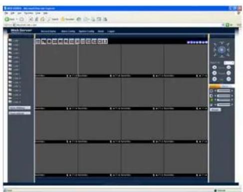
6.5.2 Connect cameras
In the previous fig, users can click on the left panel to connect to any camera or click "Open All" to connect to all the cameras.
Open All (main): In this mode, the images will be clearer and demand higher bandwidth.
Open All (Sub): In this mode, the images will be worse than main stream mode and more fluency.
Users can select above mode according to net condition.
6.5.3 Functions on View
After connecting cameras successfully, you can see interface as following.
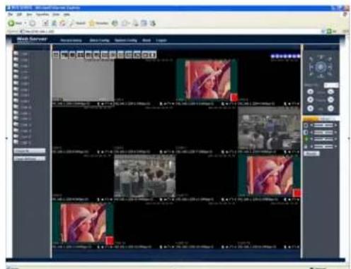
Introduction for functions on above panel:

: Click this icon to pull out the menu shown below. You can select a stream level according to your demand.
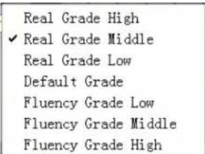
: Display images in full screen mode.
■: Display image in single-screen mode.
: Display image in 4-screen mode.
: Display image in 6-screen mode.
: Display image in 8-screen mode.
: Display image in 9-screen mode.
: Display image in 13-screen mode.
■: Display image in 16-screen mode.
20: Display image in 20-screen mode.
25: Display image in 25-screen mode.
36: Display image in 36-screen mode.
U: Click this icon to start talk back
Introduction of functions on live
192.168.1.238-1-1336Kbps-51
There are several icons at the bottom of each channel; detail information below.
192.168.1.228-10-352Kbps-S1: It shows IP address, net bandwidth and camera ID.
: Click this icon to capture picture.
☐: Click this icon to start record.
: Click this icon to start listen.
✗: Click this icon to stop view.
Introduction of functions to adjust position

: Click this icon to move image to left hand.
Click this icon to move image to down.
Click this icon to move image to right hand.
: Click this icon to move image to up.
: Click this icon to zoom in.
Click this icon to zoom out.
: Click this icon to restore image.
6.5.4 PTZ Control

6.5.5 Image Adjustment
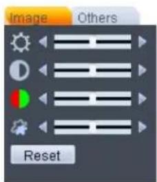
You can set bright, contrast, hue and saturation by dragging the bar in this interface
6.5.6 Others operation
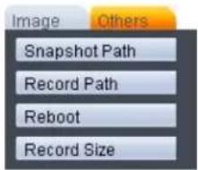
Snapshot Path: Set a path in PC to save capture images.
Record Path: Set a path to save recording files.
Reboot: Click this button to reboot device.
Record Size: Set record size range from 200MB to 1024MB.
6.6 Record Query

Select recorded type, start time, end time, recorded channel, then click “Query” to search file. In the list below (image above), you can select any recording list and click “Play” to playback files or click “Download” to download file. You can monitor cameras and playback recording files at the same time. You can also playback your local record file and view picture.

6.7 Alarm Config.
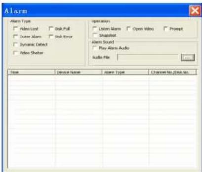
Alarm Type: Select any alarm type depending on your demand.
Operation: Set operation mode when alarm triggered.
Alarm Sound: Set a sound to alarm out when alarm triggered.
6.8 System Config.
6.8.1 System Info
In the main window, click on "config", you can see an interface is shown as below
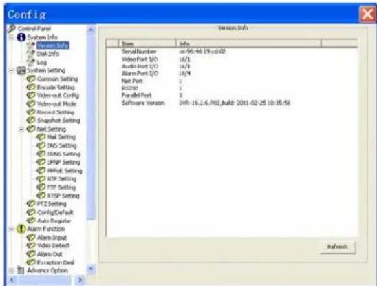
◆ System Information: Click device configuration button, you can see the following interface, Hardware version, HDD information, Interface, Log inquiry.
◆ System Setting: Setting includes the following items: General, Encode setup, Schedule, RS232, Network, MUL-DDNS, FTP, Alarm setup, Detect, Pan/Tilt/Zoom, and Tool
Advanced: set DVR's record, auto maintenance
8.2 System Setting
6.8.2.1 General Setting
General interface is shown as below.

◆ System time: To modify system time. Please click Save after your modification
◆ Date format: Select data format from the dropdown list.
◆ Date separator: Please select separator such as “—”, “/” or “.”
◆ Time format: there are two options: 24-H and 12-H.
◆ HDD full: there are two options: stop recording or overwrite the previous files when HDD is full.
◆ Language: Select system language for DVR.
◆ Device No.: When you are using one remote control to manage multiple DVRs, you can give these DVRs serial numbers respectively. Click address button in your remote control and then input the correct device number, now you can control the DVR now.
◆ Video standard: PAL or NTSC. (for your reference only)
6.8.2.2 Encode
Encode setup includes the following items
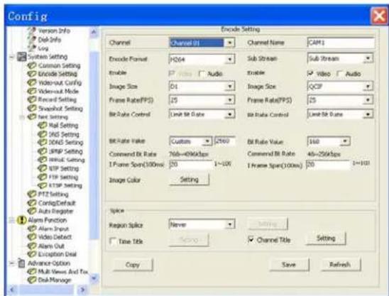
◆ Channel: Select a channel.
◆ Encode Format: H.264;
◆ Data stream: Sub stream;
◆ AV enable: Video/Audio. System only displays video by default. You need to manually enable the audio function
◆ Image Size: CIF / QCIF
◆ Differentiating rate: stocking differentiating rate's type is CIF or QCIF;
◆ Frame rate: The value ranges from 1f/s to 25f/s (PAL) and 1f/s to 30f/s (NTSC)
◆ Bit rate: There are two options: CBR and VBR. You can only set video quality in VBR mode
◆ Bit rate number: set bit rate according to web status, 10kb/s-4096kb/s adjustable;
◆ Frame interval: can set 1 frame, 2-12 optional.
◆ Image color: brightness, contrast, color, saturation and AGC for selected channel;
◆ OSD Overlay: time, title overlay.
◆ Click “copy” as following chart showing:
6.8.2.3 Record Setting
Schedule includes the following interface:
When DVR boots up, it is in 24-hour continuous record. In this interface you can set record type, record time and period. Record type includes regular record(R), motion detection record (M) and alarm record (A).
◆ Channel: select the channel number you desire.
◆ Week: you can select from the dropdown list. Or you can select at the bottom of the interface.
◆ Prerecord: system can record the three to five seconds video before activating the record operation into the file.(Depends on data size)
Period: There are six periods for you to set. Please click set button of the corresponding period. Please note all the setup here shall be in one day. E.g. 00.00 to 24.00.
6.8.3 Net Setting
User can set Email, DNS, DDNS, UPNP, PPPOE, NTP, FTP and RTSP. There are introduction of main function.
6.8.3.1 Main Setting
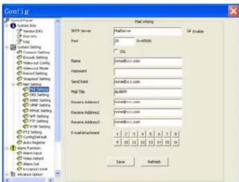
◆SMTP Server: Input server address and then enable this function.
◆Port: Default value is 25. You can modify it if necessary.
◆User Name: The sender email account user name.
◆Password: The sender email account password.
◆Sender: Sender email address.
◆Title: Input email subject here.
◆Receiver: Receiver email address.
Note: Please fulfill the postfix of the mail address if it is virtual,(e.g. xxxx@yyyy.com) otherwise it is not allowed. (e.g. xxxx)
6.8.3.2 DNS Setting
Domain Name Server (DNS). These values depend on your actual account; please contact your Internet Service Provider for details. User can a primary DNS address and a secondary DNS address.

6.8.3.3 DDNS Setting
In order to connect your DVR to the internet, you may choose to use the services of a Dynamic DNS service.

Your DVR comes with several DDNS server names built-in. To be able to use these servers, you need to go to the associated website to register for an account. Once registered, you choose the name of the DDNS Server from the list by pressing the arrow buttons located at both ends of the corresponding field and input the DDNS name, user name, password. Afterward, it should automatically connect.
6.8.3.4 UPNP
Set external HTTP Port and TCP Port which mapped in Internet.

6.8.4 Alarm Setting
User can set alarm input, alarm output, video detect and exception deal. There are introduction of the main functions below.
6.8.4.1 Alarm In
User can set alarm input parameters in this menu.
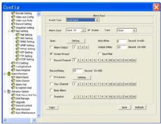
6.8.4.2 Alarm output
User can obtain Alarm output information and set alarm type.
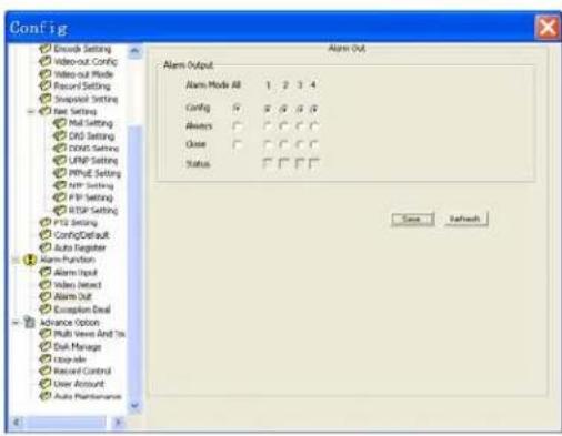
6.8.5 Advanced Option
User can manage HDD, Upgrade system, Control Record, Manage Accounts and Configure Tour.

6.9 About
You will find the web control version, NET SDK and Play SDK.
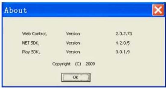
6.10 Logout
Click "Logout" to log out of system.
7. Mobile Phone Support
A state-of-the-art feature of this DVR device is transmitting live feed from the CCTV cameras to your mobile phone, so that you can have ‘on the go’ access to your surveillance system from virtually anywhere in the world. Currently, there are a limited number of phones that can support this feature: Windows CE Mobile, Symbian S60 3 ^rd Edition OS, Android, Blackberry and iPhone.
7.1 Windows Mobile

Note:
- Prior to using this feature, you should apply for the Internet connection service for your mobile phone, such as 3G or 3.5G. Please contact your mobile service provider for details.
- You can only watch one live feed channel at a time with your mobile phone. Split mode and playback of recorded files is not available at the moment.
From the installation CD, install file "vs500Setup.cab" onto your Windows Mobile phone. See your phone user manual for more details on application install.
Find and execute program VS500 and click the Setting button to setup the IP address for your DVR.
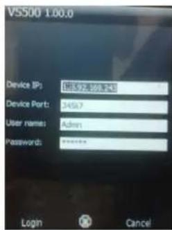
In the ensuing screen, input the user name (default is Admin), password, device port (TCP port), and IP address for your DVR (Server).
Input the value for the Port: default is 34567; choose the channel for streaming data from the dropdown menu.
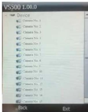
Select a camera to monitor it.

The main window of the Mobile Phone application offers the choice of channels, Connect and Settings buttons.
Up/Down: Click or to control PTZ direction upward or downward. If you click on "UP/Down", it will switch to "Left/Down" and you can control direction to left or right.
+ Zoom -: Click + or - to adjust relevant parameter. If you click on "Zoom", it
will switch to "Focus" or "Iris"
Login: Click it to enter setting interface.
Camera: Click it to enter camera selecting interface.
Full: Click it to display image in full screen mode.
About: Click it to get information about this software.
Exit: Click it to exit.
X◆\*|○●●★☆□■
Please see a sample installation process shown below (The N97 will be taken as an example to introduce installation):
(1) Copy "VS500(Symbian)V1.03.1.R.101203.sisx" to your mobile from the installation CD;
(2) Open file management on your mobile and find "VS500(Symbian)V1.03.1.R.101203.sisx" which you copied;

(3) Select "Options" and a dialog will displayed which indicates "Install VS500?" click "Ok" to continue the following steps; after you choose "OK", a series of dialog boxes will appear as displayed below; select "continue".


(4) After selecting "Ok" on last sample image displayed above, the software will start to install. After installation, there will be an icon named "VS500" in the application's interface.
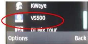
(5) Select "VS500" to execute VS500 and the program window will appear on the screen.

Device IP: DVR IP address;
Device Port: TCP port (34567 by default)
Username: Login User Name (Admin)
Password: Password (888888 by default)
(6) After configuration, select "Login" to log on to the system. The following interface will appear to select the camera you want to monitor. Select a camera then click "Back" to enter live interface.


Up/Down: Click or to control PTZ direction upward or downward. If you click on "UP/Down", it will switch to "Left/Down" and you can control direction to left hand or right hand.
+ Zoom -: Click + or - to adjust relevant parameter. If you click on "Zoom", it will switch to "Focus" or "Iris"
Login: Click it to enter setting interface.
Camera: Click it to enter camera selecting interface.
Full: Click it to display image in full screen mode.
Exit: Click it to exit.
7.3 Android Mobile
1) Install the program
1 Copy the software "VS500 (Android) V1.00.0.apk" to your Android phone or copy to SD card.
1.2 Open your "ES File Explore" in your android phone and find the [VS500(Android)V1.00.0.apk] file in your android's memory or SD Card. Click [VS500(Android)V1.00.0.apk] to install software.

VS500 provides video surveillance, channel switch, full screen magnify, PTZ control, focus and exit function.
2 System Main interface
After installation complete, select the "VS500" icon in the application to enter login interface.


Device IP: DVR IP address;
Device Port: TCP port (34567 by defaulted)
Username: Login User Name (Admin)
Password: Password (888888 by default)
After inputting the device IP address, device port, username and password, click "Login" to login system.
An interface will appear to select the camera you want to monitor (see image below).

Up/Down: Click or to control PTZ direction upward or downward. If you click on "UP/Down", it will switch to "Left/Down" and you can control direction to left hand or right hand.
+ Zoom -: Click + or to adjust relevant parameter. If
you click on "Zoom", it will switch to "Focus" or "Iris"
Video: Click it to enter camera selecting interface.
Full: Click it to display image in full screen mode.
About: Click it to get information about this software.
Exit: Click it to exit.
7.4 Blackberry Mobile
1) Program installation
- Copy the setup software "VS500.alx" and "VS500.cod" to your PC.
- In order to be able to install applications and themes via BlackBerry Desktop Manager, the PC should install Blackberry Desktop Manager first. BlackBerry Desktop Manager will be known as "DM."; otherwise the phone cannot establish the connection with the PC.
-
Connect your BlackBerry mobile phone to your computer via the USB cable that came with it, or any USB cable that fits. Start the DM.
-
Before installing, open the BlackBerry Desktop Manager. As displayed below (see red marking) on Fig 1, this means the phone is not connected to the PC. Fig 2 means the phone has been connected to the PC.
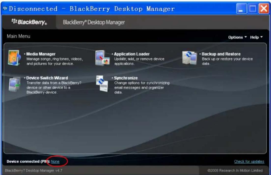
Fig 1
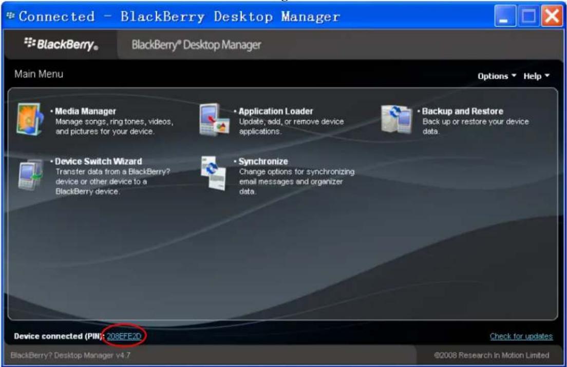
Fig 2
- Click on "Application Loader" to enter the interface. In this screen you have two options to select from. Select "Add/Remove Applications" (shown as follows).

- You should now see something like what you see below. From this screen, click "Browse" (see red marking).

- Once you click "Browse" you will see a file search screen like the one below. Search for the
application where you saved the application files. Make sure you saved both the “.alx” file and “.cod” file in the same folder. After finding the “VS500.alx” file for the application, highlight it and click “open”.

- You will now return to the Application Loader screen. From here you should see "VS500" now listed with Install under the Action column (shown as follows)

- Select "VS500" and click "Next" to go to next interface.
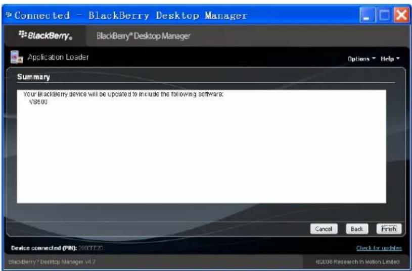
- Click "Finish" to start software installation. After installation, an interface will be displayed as follows.
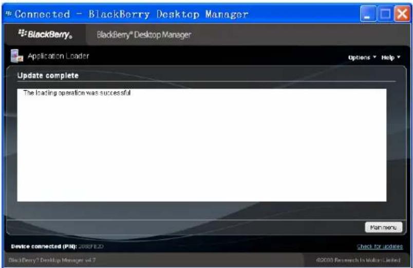
2) System explanations
VS500 phone port has the following capabilities and functions: Live video surveillance, Channel switch, Full screen display, PTZ control, including zoon/focus/iris, Image capture, save as favorite, and exit function.
① System main interface
After the installation, press the "VS500" icon in the application, see the picture below.
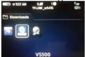
② System login interface
Open the main interface, see the configure interface bellow. Modify your parameters as necessary.

Device IP: DVR IP address
Device Port: TCP Port [34567 by default]
User name: Login User Name[Admin]
Password: Password [888888 by default]
Network Type: WIFI or others
Login: Click this button to login live interface.
Cancel: Click this button to exit system.
③ System Live interface
After setting your configurations, press [Login] to login device list and click [Cancel] button to exit. Please refer to the below picture:

Device list: Click this button to show device list and choose the one you want to connect.
④ Connect to DVR
After choose cameras, you will enter live interface.
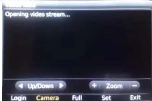
Up/Down: Click or to control PTZ direction upward or downward. If you click
on "UP/Down", it will switch to "Left/Down", you can control direction to left or right hand.
+ Zoom -: Click + or - to adjust relevant parameter. If you click on "Zoom", it
will switch to "Focus" or "Iris"
Camera: Click it to enter the camera selecting interface.
Full: Click it to display image in full screen mode.
Set: Click it to set RTSP port and stream type.
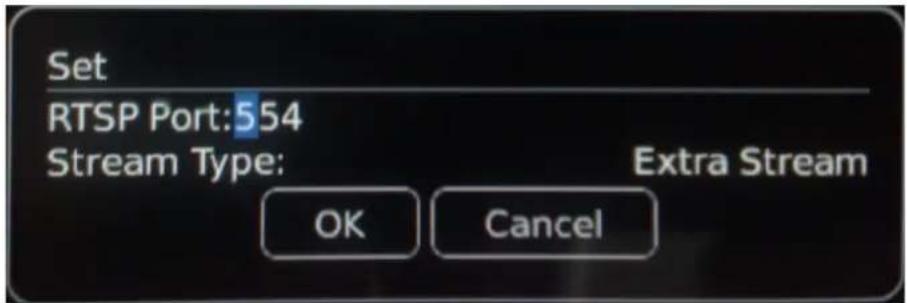
RTSP: Set RTSP port according DVR.
Stream Type: Select type between extra stream and main stream.
Exit: Click it to exit.
7.5 Apple iPhone
(1). VS500 installation.
Open iPhone App store

" as follows:
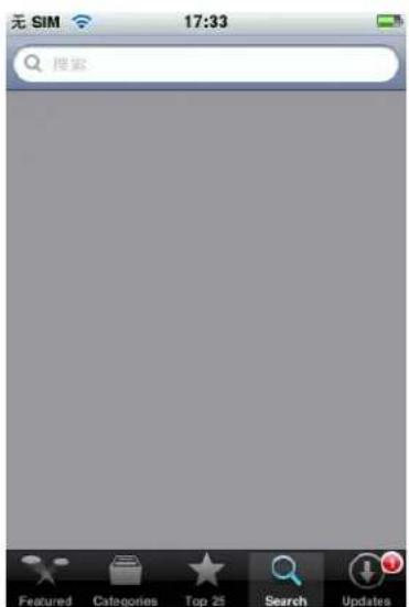
Fig 1
① Click “Search” button and search for “VS500”. It is a free application.

Fig 2
② Click “Search” and you will see following screen.
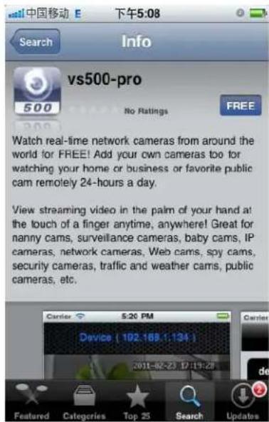
Fig 3
③ Click “Free” as shown in Fig 3. It will display the screen shown in Fig 4. Click the “install” button shown in Fig 4 “install” and it will display the screen shown in Fig 5. Input
your Apple account password, then click “”. The screen will look like the one shown in Fig 6.
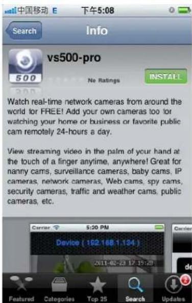
Fig 4
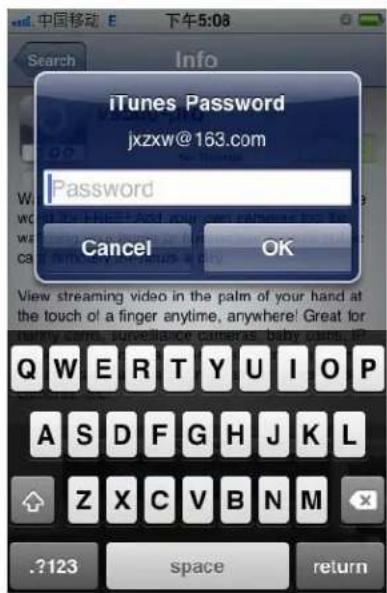
fig 5

Fig 6

: indicates that the “VS500” software is downloading ..... When the “
"process bar
is full “☐”, the VS500 software has finished installing.
After installing "VS500", the iPhone screen will display the screen shown in Fig7.
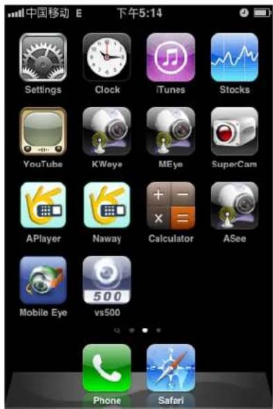
Fig 7
(2). How to use VS 500.
①. Click the "VS 500" icon to open the "VS 500" to set up parameters.
Device IP: DVR IP address
Device Port: TCP Port [34567 by default]
User name: Login User Name[Admin]
Password: Password [888888 by default]

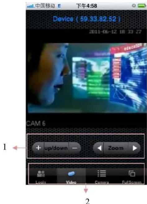
Fig 8
Fig 9
-
PTZ Control: Click + or - to control PTZ direction upward or downward. If you click on "UP/Down", it will switch to "Left/Down" and you can control the direction left or right. Click ▶ or ▶ to adjust relevant parameter. If you click on "Zoom", it will switch to "Focus" or "Iris"
-
Login: Click it to set up parameters.
Camera: Click it to enter camera the selecting interface.
Full Screen: Click it to display image in full screen mode.
Appendix 1 Setting up Internet Connections for Remote Access
This section will explain the ways to connect your DVR to the internet using static and dynamic IP addresses. To connect to the internet, you will need to use a modem and a router.
As a network device, your DVR should have its own address called an Internet Protocol (IP) address. This address can be used by other network devices (i.e. computers) to access the DVR to remotely monitor the CCTV cameras and change settings. You can get a static IP address from your internet service provider – this way you will always have the same address at all times, though this method is rather expensive. If you have a static IP, enter your static IP in the DVR settings and the router will connect your DVR to the internet.
You may alternatively choose to use dynamic IP, which means that the IP address of your DVR may frequently change, but it will still be possible to find your DVR from remote computers, by using DDNS (Dynamic Domain Name System) which dynamically assigns IP addresses to the DVR. This functionality allows the DVR to automatically update its IP address to the DDNS Server each time its Dynamic IP address changes. Your DVR is equipped with the DDNS functionality and has a list of related domain names through which you can acquire an IP address. (See Section 5.4.3 for details.)
Setup an account with a DDNS service provider and with the account information available, login to the router and go to the DDNS page. Select the address of your service provider and type in the account password. After saving, the router will send IP updates to your DDNS account and the connection will always be forwarded to you current IP.
Appendix 2 Compatibility Table for HDDs
Below is the list of tested Hard Disk Drives, found to be compatible with the DVR. If you want to use a HDD not found in this list, please test it for compatibility before use.
| Brand name | Model Number | Size (GB) | Drive | |
| Scagate | ST3250318AS | 250G | SATA | |
| Seagate | ST3320410SV | 320GB | SATA | |
| Scagate ST33 | 20613AS | S7200.11 320G | SATA | |
| Seagate ST35 | 00413AS | S7200.12 500GB | SATA | |
| Seagate ST35 | 00418AS | S7200.12 500G | SATA | |
| Scagate ST35 | 00320AS | SV35.3 500G | SATA | |
| Seagate | ST31000340AS | S7200.11 | 1000G | SATA |
| Scagate | ST31000333AS | 1T | SATA | |
| Scagate | ST31000528AS | 1T | SATA | |
| Seagate | ST31500341AS | S7200.11 | 1.5T | SATA |
| Scagate | ST32000542AS | 2T | SATA | |
| WD | WD3200AVJS | 320GB | SATA | |
| WD | WD5000AAKX | 500GB | SATA | |
| WD | WD10EACS-OOD6B0 | 1.0TB | SATA | |
| WD | Caviar green-WD20EARS | 2T | SATA | |
| Samsung | HD103SI | 1T | SATA | |
| Hitachi | HDP725050GLA360 | 500GB | SATA |
Appendix 3 List of Compatible Portable USB DVD Recorders
Please find below the list of tested portable USB DVD recorders found to be compatible with the DVR. If for backing up your data from the DVR, you wish to use a DVD recorder not found on this list, please test it for compatibility.
- Pioneer DVR-XD09C
Appendix 4 List of Compatible Portable SATA DVD Recorders(Only for 8CH and 16CH D1 series)
Below is the list of tested portable SATA DVD recorders found to be compatible with this DVR. If for backing up your data from the DVR, you wish to use a DVD recorder not found on this list, please test it for compatibility.
•LG GH22NS50
-SONY AD-7260S
●SAMSUNG TS-H663
●LITEON IHAS324-25Y
Appendix 5 Limited 1 Year Warranty
This warranty gives the original purchaser specific legal rights and you may also have other rights, which may vary from state to state. If our products do not function because of any defect in material or workmanship, we will repair it for free for 1 year on parts and labor from the date of original purchase. This warranty does not cover modification, abuse, incidental or consequential damages unless the state of owner's residence specially prohibits limitations on incidental or consequential damages.
Appendix 6 How to Obtain Factory Service
- Original purchaser must fill out the warranty card and mail it to the factory with the model number, serial number and the date of purchase.
• We will repair or replace, and return the system to the owner under this limited warranty. - Please pack the system carefully and securely using the original packing materials, and send it prepaid and insured to: 13073 E. 166th St, Cerritos, CA 90703.
- Please include a check for \$25.00 to cover the cost of return postage and handling. If the system is returned within the warranty period, please include a proof of purchase. If the system is out of warranty, you will receive an estimate of the repair cost for your approval before repair work will be started.
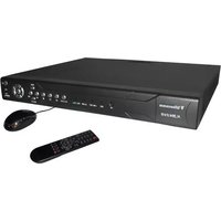
- CAUTION!
- WARNING
- LIMITATION OF LIABILITY
- DISCLAIMER OF WARRANTY
- SAFETY INSTRUCTIONS
- CARING FOR THE ENVIRONMENT BY RECYCLING
- Recycling your Electrical Equipment
- COPYRIGHT STATEMENT
- Table of Contents
- DVR SETTINGS....38
- WEB BROWSER OPERATION....69
- OPERATION INTERFACE....74
- RECORD QUERY 78
- ALARM CONFIG....78
- SYSTEM CONFIG 79
- System Setting....80
- Net Setting....82
- Alarm Setting 84
- Advanced Option....85
- ABOUT....86
- LOGOUT 86
- MOBILE PHONE SUPPORT ....86
- APPENDIX 1 SETTING UP INTERNET CONNECTIONS FOR REMOTE ACCESS....101
- APPENDIX 2 COMPATIBILITY TABLE FOR HDDS ....101
- APPENDIX 3 LIST OF COMPATIBLE PORTABLE USB DVD RECORDERS....102
- APPENDIX 4 LIST OF COMPATIBLE PORTABLE SATA DVD RECORDERS (ONLY FOR 8CH AND 16CH D1 SERIES)....103
- YOUR DVR AT A GLANCE
- Product Overview
- Model dependent
- Contents of the Box
- Getting Started Check-List
- Hardware
- Front Panel (Please take actual machine model as quasi)
- Back Panel (Please take actual machine model as quasi)
- CIF 16 CH
- Audio Input Connector (CH1--8) & Audio out
- Video Input Connectors (Video IN 1-16)
- Video Output Connector
- Ethernet Connector
- ESATA
- Power Switch.
- Alarm Input/Output connector (Alarm IN: 4 CH, Alarm Out: 1 CH)
- Alarm Output Connectors (pin
- NO-COM) ---- (optional)
- RS-485 Connector (pin A-B) ---- (optional)
- MIC
- USB connectors
- VGA Connector---- (optional)
- Power Input Socket (12V DC)
- Remote Control
- Mouse Control
- Hardware Installation
- Basic Connections
- ■ Cameras
- ■ Audio Connection
- ■ Monitor
- Power
- ■ Alarm Input / Output----(optional)
- Ethernet
- USB
- Installing Hard Disk Drive
- PTZ Control Connections---- (optional)
- Getting Started and the Main Screen
- The Main Screen
- Displaying a Single Channel
- Login System
- Shortcut menu
- Shortcut Menu Options
- Main Menu
- Record Playback
- Playback Control
- Video Backup
- Playing backed up video on your PC
- Record Control
- Alarm Output
- PTZ Control
- Color Setting
- TV Adjustment
- Logout
- Screen View Modes
- Channel Status Display
- DVR Settings
- Main Menu
- Menu Options
- Record Settings
- Schedule
- Search
- Record Backup
- Alarm Setting
- Motion Detection
- Camera Masking
- Video Lost
- Alarm Input
- Alarm Output
- Abnormity
- System Settings
- General Setting
- Encode Setting
- Network Setting
- Display Setting
- Account Setting
- PTZ Setting
- RS232
- Tour Setting
- Advanced Setting
- HDD Manage
- USB Upgrade
- Configuration
- Maintenance
- Default
- Shut Down
- Information
- HDD Information
- Note:
- BPS
- Log
- Version
- Web Browser Operation
- Software Environment
- Hardware
- Software
- RESTRICTION CONDITION :
- Network Security Setting
- Set the ActiveX control and pluggable unit. Select the following options
- Connection Setting
- Control Download and Installation
- Operation Interface
- Live
- Connect cameras
- Functions on View
- PTZ Control
- Image Adjustment
- Others operation
- Record Query
- Alarm Config.
- System Config.
- System Info
- System Setting
- General Setting
- Encode
- Record Setting
- Net Setting
- Main Setting
- DNS Setting
- DDNS Setting
- UPNP
- Alarm Setting
- Alarm In
- Alarm output
- Advanced Option
- About
- Logout
- Mobile Phone Support
- Windows Mobile
- X◆\*|○●●★☆□■
- Android Mobile
- 1) Install the program
- Blackberry Mobile
- 1) Program installation
- 2) System explanations
- ① System main interface
- ② System login interface
- ③ System Live interface
- ④ Connect to DVR
- Apple iPhone
- Appendix 1 Setting up Internet Connections for Remote Access
- Appendix 2 Compatibility Table for HDDs
- Appendix 3 List of Compatible Portable USB DVD Recorders
- Appendix 4 List of Compatible Portable SATA DVD Recorders(Only for 8CH and 16CH D1 series)
- Appendix 5 Limited 1 Year Warranty
- Appendix 6 How to Obtain Factory Service
Brand : Clover Electronics
Model : CDR0420
Category : Voice recorder