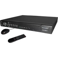
DV1630 - Voice recorder Clover Electronics - Free user manual and instructions
Find the device manual for free DV1630 Clover Electronics in PDF.


| Product Type | Digital Video Recorder (DVR) with Voice Recording |
| Brand | Clover Electronics |
| Model | DV1630 |
| Video Input Channels | Up to 16 |
| Video Output | Main TV (BNC), Spot TV, VGA |
| Audio Input/Output | RCA connectors for microphone and speaker |
| Alarm Input/Output | 8 alarm inputs, 4 alarm outputs (N/C or N/O) |
| Network Interface | Ethernet (10/100Base-T), RJ-45 |
| Storage | Internal SATA HDD (up to 2TB?), USB backup |
| Power Supply | AC/DC adapter 12V DC, 4A |
| Recording Resolution | NTSC: 704x480 (D1), 704x240 (HD1), 352x240 (CIF); PAL: 704x576, 704x288, 352x288 |
| Recording Frame Rate | NTSC: up to 30fps (D1), PAL: up to 25fps (D1) |
| Video Compression | H.264 |
| PTZ Control | RS-485, supports multiple protocols |
| Remote Control | Infrared remote controller included |
| Mouse Support | PS/2 wheel mouse (hot-plug) |
| Software | CMS (Central Monitoring Software) for PC |
| Web Viewer | Internet Explorer (ActiveX) for remote access |
| Mobile Viewer | iPhone, Android, Windows Mobile, Symbian |
| Operating Temperature | Up to 104°F (40°C) |
| Dimensions | Desk mount, approx. 1U height (exact not specified) |
Frequently Asked Questions - DV1630 Clover Electronics
User questions about DV1630 Clover Electronics
0 question about this device. Answer the ones you know or ask your own.
Ask a new question about this device
Download the instructions for your Voice recorder in PDF format for free! Find your manual DV1630 - Clover Electronics and take your electronic device back in hand. On this page are published all the documents necessary for the use of your device. DV1630 by Clover Electronics.
USER MANUAL DV1630 Clover Electronics
Chapter 1. Installation
System Requirements 3 l n s t a l l a t 3 i o n
Chapter 2. Operation
Run BackupViewer 5
BackupViewer screen 6
Open Backup file 7
Playback control 8
Screen layout control 9
Screen capture 9
AVI backup 9
Chapter 1. Installation
System Requirements
CPU : Intel Pentium4, 2.0GHz or Higher
RAM : 256MB or higher
VGA : 1024x768, 24bit or 32bit color
Installation
Step 1. Execute setup program
Open the folder where setup file is located and double click the setup file to start.

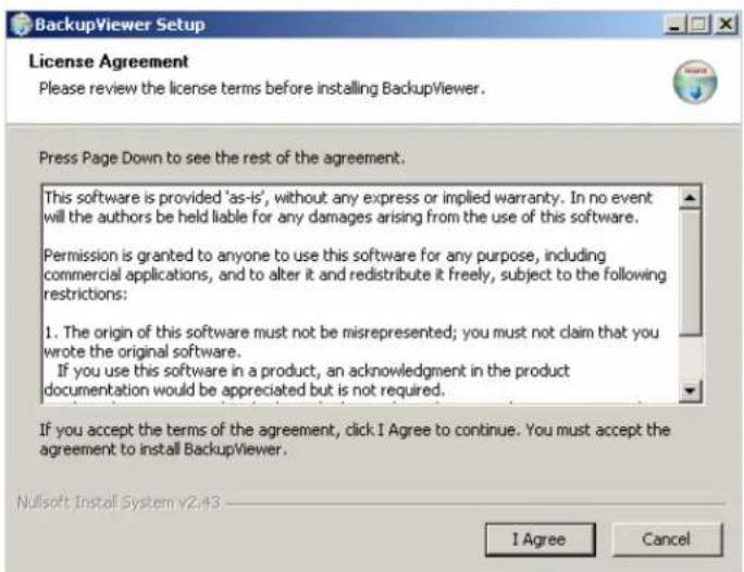
Step 2. License Agreement
Click the "I Agree" button to proceed to the next step.
Step 3. Select language
Choose the language for installation and click "OK" to proceed to the next step.

Step 4. Choose Destination & Start to install
Choose the destination folder you want to install and click the "Install" button.
Installation will start as soon as you click "Install".

Step 5. Finish
Click the "Close" button to finish installation.

Chapter 2. Operation
Run BackupViewer
There are two options to run BackupViewer; choose the option you prefer.
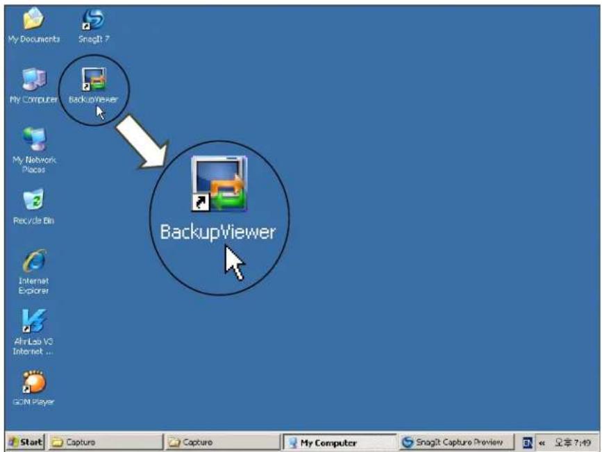
1 ^st Option: BackupViewer icon on your desktop
You can find BackupViewer icon on your Windows® desktop screen.
Double-click this icon to start Backup Viewer.
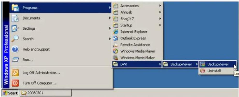
2 ^nd Option: BackupViewer on Start menu
You can find BackupViewer through Start>Program>DVR>BackupViewer menu.
BackupViewer screen
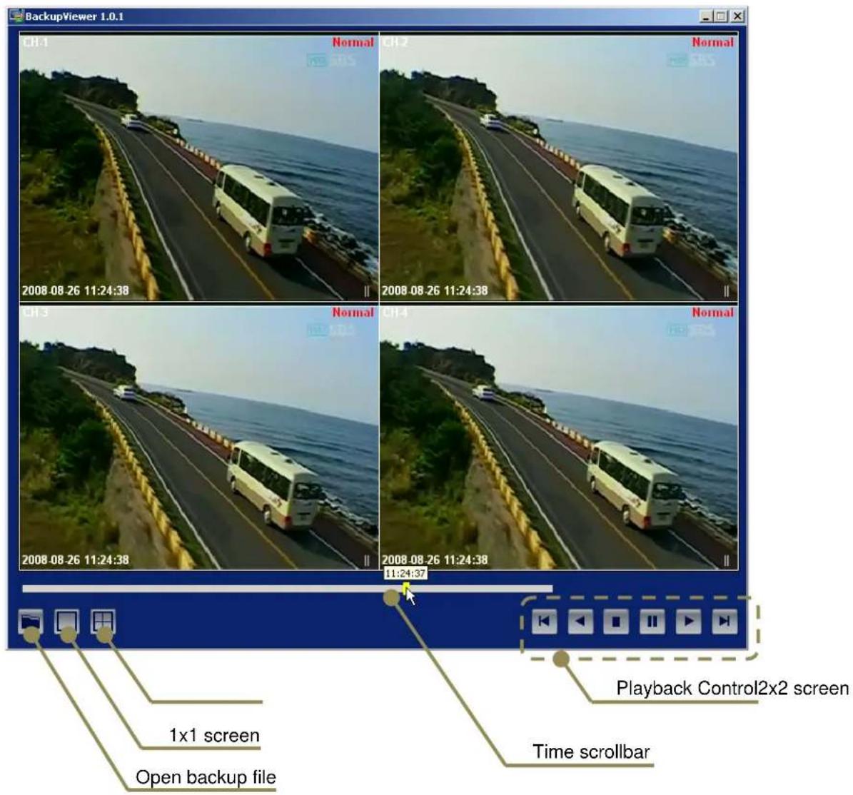
Open a backup file
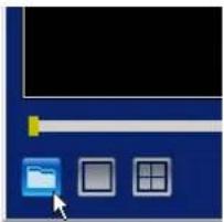
1 ^st Option: using the “Open” icon
Click the "Open" icon on the bottom-left side of the screen.
natural_image
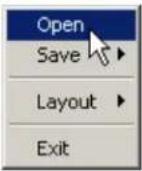
Computer monitor interface with scroll bar and two window icons (no text or symbols)2^nd Option: Using the menu panel
Right click on mouse button to open a menu panel.

Open file window will be displayed.
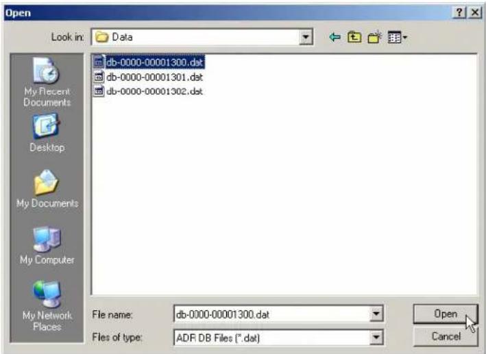
Choose a backup file, and click the "Open" button.
Playback control buttons

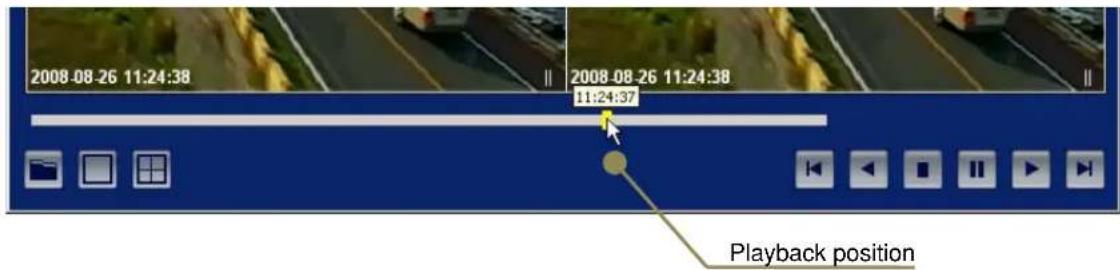
Playback position display and control
This scroll bar is indicating your current playback position in the backup file.
In addition, you can jump into a specific position to playback by dragging the scroll bar.
Step 1) Move mouse pointer on the scroll bar (yellow rectangle).
Step 2) Left click and hold the mouse button, and drag the cursor to desired playback position.
Playback time will appear above the scroll bar.
Step 3) Release left mouse button and playback will be start.
Screen layout control
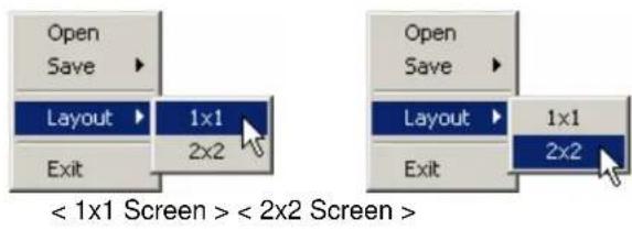
You can change the screen layout using GUI or menu panel.
Using GUI Using menu panel

Screen capture
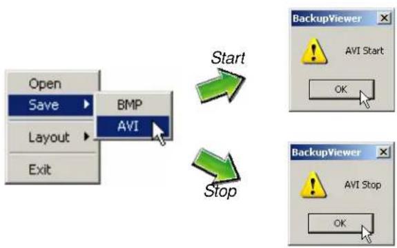
Right click mouse button to open a menu pane at 1x1 screen mode, and choose "BMP" menu to capture. A still image is captured in BMP format on BackupViewer folder.

AVI backup
Right click mouse button to open a menu pane at 1x1 screen mode, and choose "AVI" menu to start or stop AVI backup. A video clip will be created in AVI format on BackupViewer folder.
flowchart
graph TD
    A["Open"] --> B["Save"]
    B --> C["Layout"]
    C --> D["Exit"]
    E["BMP"] --> F["AVI"]
    G["Start"] --> H["Stop"]
    I["Stop"] --> J["AVI Stop"]
    K["BackupViewer"] --> L["AVI Start"]
    M["BackupViewer"] --> N["AVI Stop"]
Instruction Manual
Digital Video Recorder
CMS (Central Monitoring Software)
Model: DV1630, PAC161558
Chapter 1 Installation
System Requirements 3 1 n s t a l l a t 3 i o n
Chapter 2 Operation
Run CMS software 5
CMS Software login 6
CMS Main screen 6
Register DVR 7
Connect/Disconnect DVR 8
Live 9
Search 11
E - Map 12
PTZ 14
Alarm In/Out 15
Event 15
Back-up 16
DVR Setup 17
DVR Upgrade 18
CMS Options & Version 18
Screen Capture 20
Chapter 1 Installation
System Requirements
CPU : Intel Pentium4, 2.4GHz or Higher
RAM : 512MB or higher
VGA : 1280x1024, 24bit or 32bit color or higher
Installation
Step 1. Run [CMSSetup.exe].

Step 2. Click the "I Agree" button.

Step 3. Click the "Install" button.
Choose destination folder you want to install.
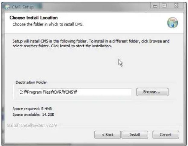
Step 4. Click "Close" when Installation is complete.
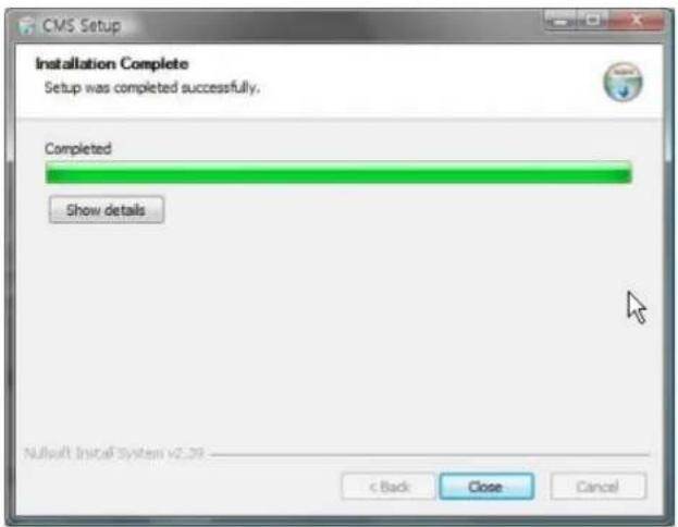
Chapter 2. Operation
Run CMS software
There are two options to run the CMS software; choose the option you prefer.

Windows
Vista/7
User
User should run CMS software with Administrator authority in Windows Vista/7. (Right-click the mouse button on the CMS icon and select "Run as administrator")
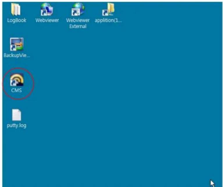
1 ^st Option: CMS icon on desktop
You can find an icon of the CMS on your Windows® desktop screen. Double-click this icon to start CMS software.
2^nd Option: CMS software on Start menu
You can find CMS through Start>Program>DVR>CMS menu.
CMS software login
When you begin CMS/ login window will appear at the first.
Input password then click the Login.
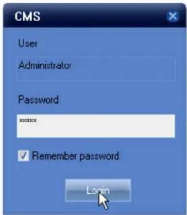
Default Password is "1111"
If the "Remember password" is checked, your password will be pre-filled next time you run the CMS Software.
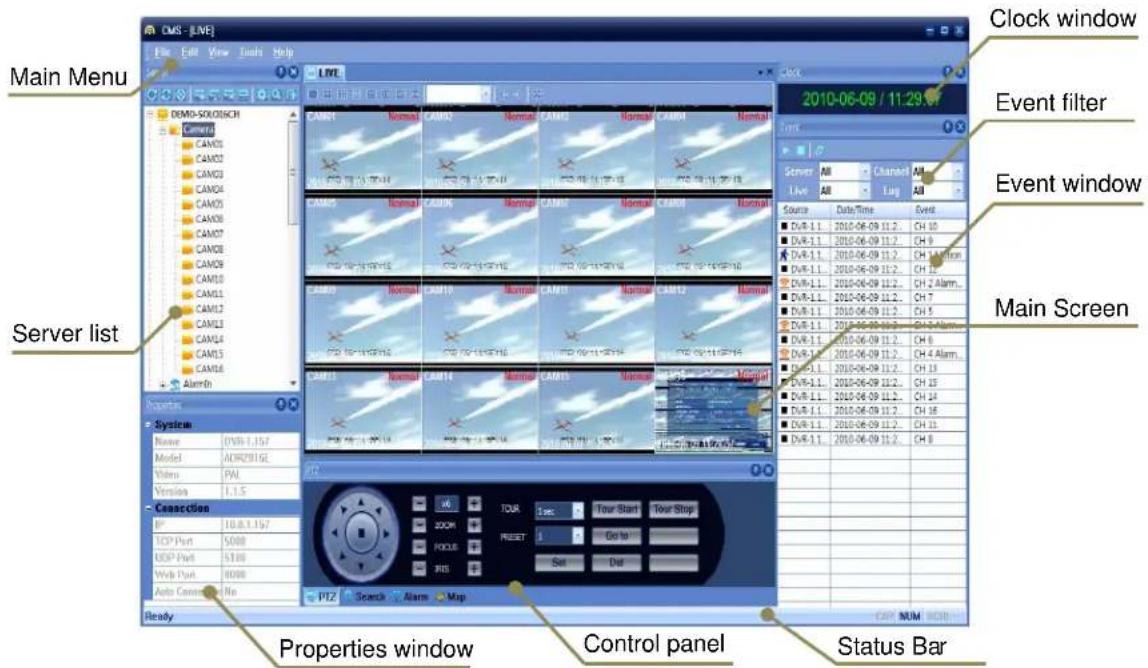
CMS Main screen
Register DVR
There are two options for Server registration.
1 ^st Option: Auto Registration
This option is available when DVR and CMS are in same network.
- Click the Scan button [ ] in Server list window. The below window will appear.
- Click "Scan" button.

-
Double click the list.
-
Input the values below.

- Click "OK" when information entered.
2 ^nd Option: Manual registration
- Click the Add icon [ ] in Server list window. The below window will appear.
- Input the values below.

- Click "OK" when information is entered.
Connect/Disconnect DVR
Connect
- Click the Connect icon [ ] to connect the registered DVR.
The DVR icon is changed from blue to yellow.

Disconnect
- Click the Disconnect icon [ ☑ ] to disconnect the DVR.

Click the Connect All icon [ ] to connect the all registered DVRs.
Live
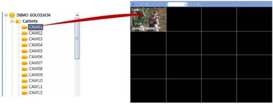
Camera view
Drag a camera icon [ - CAM01 ] like the below. The selected camera is displayed on view panel.
Stop searching at 1 channel search
Right-click mouse button on the searching channel in red and select [Live -> Stop] from the menu.
DVR view
Drag a group icon [ ] as shown below. The selected cameras are displayed in on view panel.

Page 9 of 20
View Layout
Select a view layout button.
Full Screen
![[4x4] 3+4 Normal View Special View Next/Previous](/content/2026/05/1066911/images/64b89ac46b137e83271204c0566d349ce94d27c73f97afd728e2a35b6e1e06b8.jpg)
- Normal view: 1, 4, 9, 16, 25, 36, 49, 64
- Special view: [3x3] 1+5, [4x4] 1+12, [4x4] 2+8, [4x4] 3+4, [5x5] 1+9, [5x5] 4+9
- Next / Previous : Shows the next or previous cameras in the selected view layout.
- Full screen : Shows the view layout as full screen without GUI.
Search
Search Mode
- Select a DVR.
- Click the Search icon [ 🔒 ] and the control panel is changed to search mode as below.


Playback
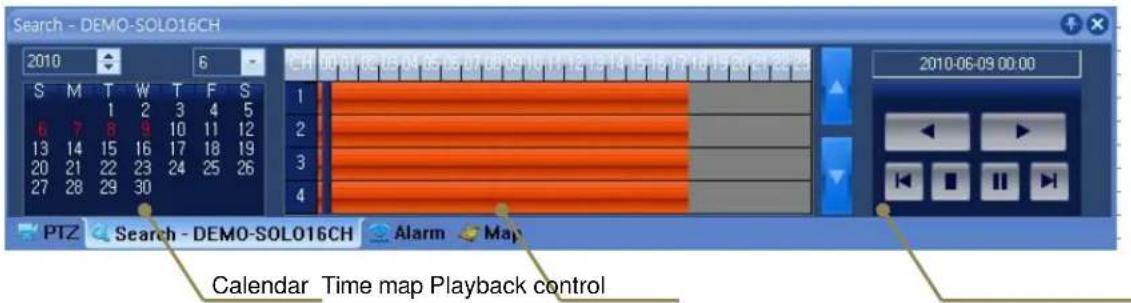
- Select a date from the calendar. (Dates with recorded data are marked in red)
- Select a time from time map.
- Search the recorded images with playback control.

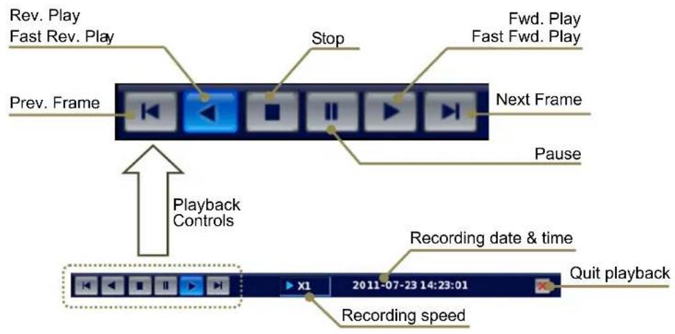
Playback Control
Rev. Play Fast Rev. Play
Prev. Frame
Stop
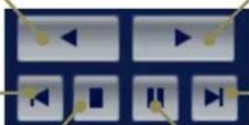
Fwd. Play Fast Fwd. Play
Next Frame
Pause
E-Map
Select the Map option from the View menu, The "Empty-Map" Tab is displayed.

Add Map
- Right-click mouse button on Map view.
- Select a New Map from the menu.

- Input the map name in "Name" field.
- Find a map image by clicking the icon [ ... ]. The selected image is displayed in preview.
- Click "OK".

User can drag a camera/alarm in/alarm out to map image as shown below.
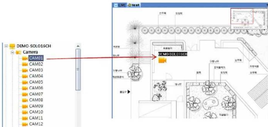
Camera view & Alarm In/Out control
Double-clicked the camera on map; the camera image will be displayed.
If you double-click alarm in/out on map, the user can control the alarm in/out.
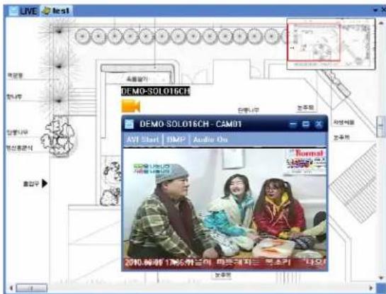
Map Save
User can right-click the mouse button on the "Map view" and save the map by selecting "Save Map Group".
Map load
User can right-click the mouse button on map view and load the map by selecting "Load Map Group".
PTZ
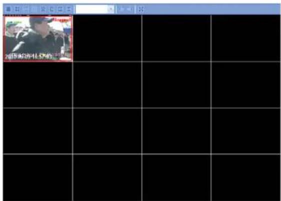
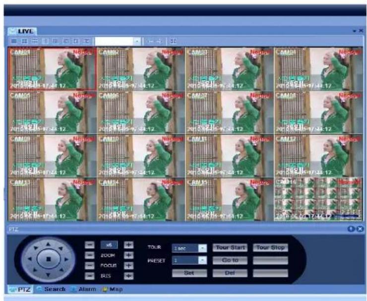
User can use PTZ control by selecting the camera with PTZ on view panel. (The selected camera is marked in red.)
![Properties System Name DEMO-SOL016 General Name CAM01 Channel 0 Enabled Yes Audio Enabled Yes PTZ None Size FPS FPS[Network] Quality Quality[Network]](/content/2026/05/1066911/images/9520551c8f5807405d20d91441e95d24061e237781b22d1953e88b483342efbe.jpg)
Alarm In/Out
User can control alarm in/out in the Alarm tab of Control window.
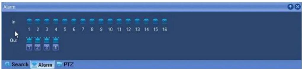
If Alarm In/Out is working, the color is changed to orange.
Event
Event window displays all events of the connected DVRs on the Server list.

Event show
Click the Event Start Icon [▶] on the DVR to display the event working status on the event list.
Event hide
Click the Event Stop icon [ ] to hide the event working status on the event list.
Event delete
Click the Event Clear icon [ ] to delete the event list.
Event Search
User can search a specific event by using the event filter like Server, Channel, Live, and Log.
Event Save
User can save the selected event by right-clicking the mouse button on that event.
From the pop-up menu, select "Save". (CSV file format is open on Excel)
Backup
User can backup the recorded data of DVR by right-clicking the mouse button on the connected DVR on Server list window. From the pop-up menu, select "Backup".


For remote backup, we recommend to stop Live/Search because system performance may fail.
DVR Setup
Click the Setup icon [ ✪ ] in Server list window on the connected DVR. The setup window is displayed. User can change the setting values of the connected DVR.
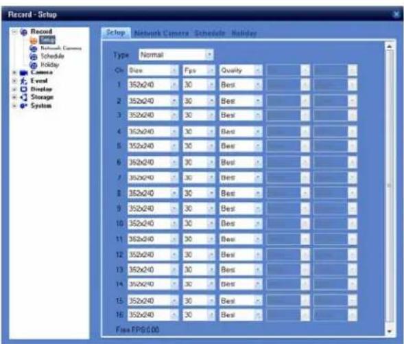

TIP
Click the exit button(X) of window to exit the setup window. The below message is displayed.

DVR Upgrade
Click the Upgrade Icon [ ] in Server list window on the connected DVR.
User can upgrade the Kernel and Firmware of the DVR remotely.
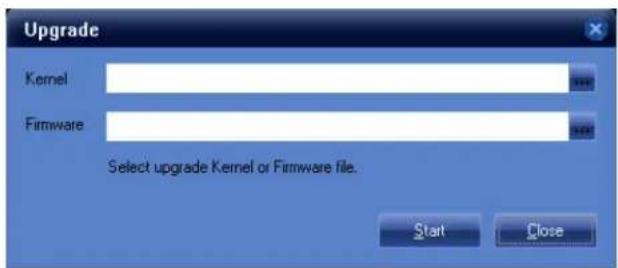
Find the path by clicking the icon [...] for Kernel or Firmware upgrade and click the "Start" button. After upgrade, the connection is disconnected.
CMS Options & Version
User can set user id, password and view layout of CMS.
Administrator Password
Click Menu Option – Account. You must use the same password and input in Password and Confirm fields.


Please check "Automagic Login" for CMS auto login.
View layout
Click the Screen selection to view Layout Setup.
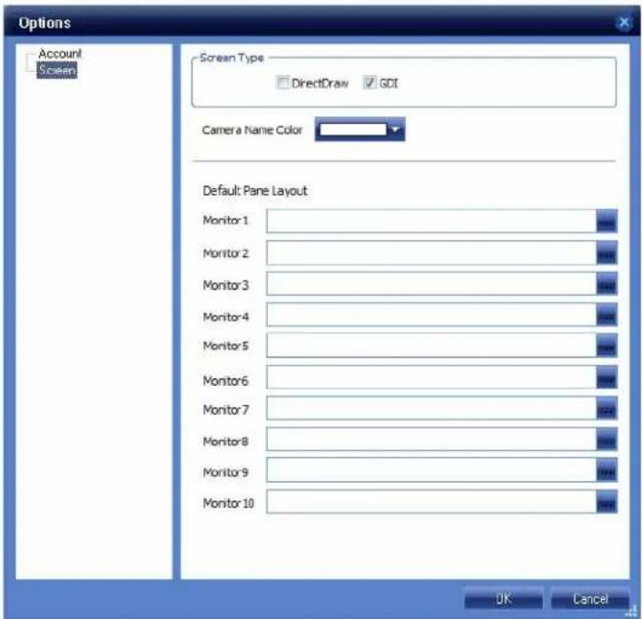
Screen Type: "DirectDraw" is to use the Direct Draw of MS Direct X. It displays images with full performance of the graphic card; it is also good for image quality and speed.
“GDI” is to use GDI technique of MS. It is slower than DirectDraw but has good compatibility and stability.
Camera Name Color: Change the background color of the camera name on view panel.
Default Panel Layout: User can select a view layout for each monitor when multi monitors are used.
Version: Displays CMS version information.
Click Menu / Help / About for version information.

Screen capture
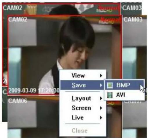
BMP Capture
- Select the Camera on the view panel.
- Right-Click the mouse button on the camera.
- Select Save / BMP from the pop-up menu.
- The still image is saved on a path as shown below.
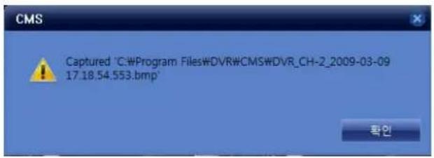

Default Directory is c:\Program Files\DVR\CMS.
Default Filename is DVR name_CH_year-mm-dd-hh-mm-ss.bmp.
AVI file Capture
- Select the camera on view panel.
- Right-Click on the selected camera.
- Select Save / AVI from pop-up menu.
- Click "OK". The AVI file is saved.
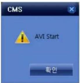
Default Directory is c:\Program Files\DVR\CMS.
Default Filename is DVR name_CH_year-mm-dd-hh-mm-ss.avi.
Instruction Manual
Digital Video Recorder
Model: DV1630, PAC161558
Chapter 1 Installation
| Contents of the box | ||||||||||||||||||||||||||||||||||||||||||||||||||||||||||||||||||||||||||||||||||||||||||||||||||||||||||||||||||||||||||||||||||||||||||||||||||||||||||||||||||||||||||||||||||||||||||||||||||||||||||||||||||||||||||||||||||||||||||||||||||||||||||||||||||||||||||||||||||||||||||||||||||||||||||||||||||||||||||||||||||||||||||||||||||||||||||||||||||||||||||||||||||||||||||||||||||||||||||||
| Choosing a location for installation | ||||||||||||||||||||||||||||||||||||||||||||||||||||||||||||||||||||||||||||||||||||||||||||||||||||||||||||||||||||||||||||||||||||||||||||||||||||||||||||||||||||||||||||||||||||||||||||||||||||||||||||||||||||||||||||||||||||||||||||||||||||||||||||||||||||||||||||||||||||||||||||||||||||||||||||||||||||||||||||||||||||||||||||||||||||||||||||||||||||||||||||||||||||||||||||||||||||||||||||
| I | n | s | t | a | l | l | a | t | 6 | i | o | n | ||||||||||||||||||||||||||||||||||||||||||||||||||||||||||||||||||||||||||||||||||||||||||||||||||||||||||||||||||||||||||||||||||||||||||||||||||||||||||||||||||||||||||||||||||||||||||||||||||||||||||||||||||||||||||||||||||||||||||||||||||||||||||||||||||||||||||||||||||||||||||||||||||||||||||||||||||||||||||||||||||||||||||||||||||||||||||||||||||||||||||||||||||||||||||||||||
| Rear | panel | layout | 6 | 6 | ||||||||||||||||||||||||||||||||||||||||||||||||||||||||||||||||||||||||||||||||||||||||||||||||||||||||||||||||||||||||||||||||||||||||||||||||||||||||||||||||||||||||||||||||||||||||||||||||||||||||||||||||||||||||||||||||||||||||||||||||||||||||||||||||||||||||||||||||||||||||||||||||||||||||||||||||||||||||||||||||||||||||||||||||||||||||||||||||||||||||||||||||||||||||||||||||||||||||
| Basic | connections | 6 | ||||||||||||||||||||||||||||||||||||||||||||||||||||||||||||||||||||||||||||||||||||||||||||||||||||||||||||||||||||||||||||||||||||||||||||||||||||||||||||||||||||||||||||||||||||||||||||||||||||||||||||||||||||||||||||||||||||||||||||||||||||||||||||||||||||||||||||||||||||||||||||||||||||||||||||||||||||||||||||||||||||||||||||||||||||||||||||||||||||||||||||||||||||||||||||||||||||||||||
| Connect audio devices (optional) | 7 | |||||||||||||||||||||||||||||||||||||||||||||||||||||||||||||||||||||||||||||||||||||||||||||||||||||||||||||||||||||||||||||||||||||||||||||||||||||||||||||||||||||||||||||||||||||||||||||||||||||||||||||||||||||||||||||||||||||||||||||||||||||||||||||||||||||||||||||||||||||||||||||||||||||||||||||||||||||||||||||||||||||||||||||||||||||||||||||||||||||||||||||||||||||||||||||||||||||||||||
| Connect alarms (optional) | 7 | |||||||||||||||||||||||||||||||||||||||||||||||||||||||||||||||||||||||||||||||||||||||||||||||||||||||||||||||||||||||||||||||||||||||||||||||||||||||||||||||||||||||||||||||||||||||||||||||||||||||||||||||||||||||||||||||||||||||||||||||||||||||||||||||||||||||||||||||||||||||||||||||||||||||||||||||||||||||||||||||||||||||||||||||||||||||||||||||||||||||||||||||||||||||||||||||||||||||||||
| Connect RS-485 PTZ camera (optional) | 7 | |||||||||||||||||||||||||||||||||||||||||||||||||||||||||||||||||||||||||||||||||||||||||||||||||||||||||||||||||||||||||||||||||||||||||||||||||||||||||||||||||||||||||||||||||||||||||||||||||||||||||||||||||||||||||||||||||||||||||||||||||||||||||||||||||||||||||||||||||||||||||||||||||||||||||||||||||||||||||||||||||||||||||||||||||||||||||||||||||||||||||||||||||||||||||||||||||||||||||||
| Connect to network (optional) | 8 | |||||||||||||||||||||||||||||||||||||||||||||||||||||||||||||||||||||||||||||||||||||||||||||||||||||||||||||||||||||||||||||||||||||||||||||||||||||||||||||||||||||||||||||||||||||||||||||||||||||||||||||||||||||||||||||||||||||||||||||||||||||||||||||||||||||||||||||||||||||||||||||||||||||||||||||||||||||||||||||||||||||||||||||||||||||||||||||||||||||||||||||||||||||||||||||||||||||||||||
| Connect a mouse (optional) | 8 | |||||||||||||||||||||||||||||||||||||||||||||||||||||||||||||||||||||||||||||||||||||||||||||||||||||||||||||||||||||||||||||||||||||||||||||||||||||||||||||||||||||||||||||||||||||||||||||||||||||||||||||||||||||||||||||||||||||||||||||||||||||||||||||||||||||||||||||||||||||||||||||||||||||||||||||||||||||||||||||||||||||||||||||||||||||||||||||||||||||||||||||||||||||||||||||||||||||||||||
| Connect power | 8 | |||||||||||||||||||||||||||||||||||||||||||||||||||||||||||||||||||||||||||||||||||||||||||||||||||||||||||||||||||||||||||||||||||||||||||||||||||||||||||||||||||||||||||||||||||||||||||||||||||||||||||||||||||||||||||||||||||||||||||||||||||||||||||||||||||||||||||||||||||||||||||||||||||||||||||||||||||||||||||||||||||||||||||||||||||||||||||||||||||||||||||||||||||||||||||||||||||||||||||
| T | i | m | e | a | d | j | u | 9 | s | t | m | e | e | e | e | e | e | e | e | e | e | e | e | e | e | e | e | e | e | e | e | e | e | e | e | e | e | e | e | e | e | e | e | e | e | e | e | e | e | e | e | e | e | e | e | e | e | e | e | e | e | i | n | s | t | a | l | l | a | t | 6 | i | o | n | n | n | n | n | n | n | n | n | n | n | n | n | n | n | n | n | n | n | n | n | n | n | n | n | n | n | n | n | n | n | n | n | n | n | n | n | n | n | n | n | n | n | n | n | n | n | n | n | n | m | e | a | d | j | u | 9 | s | t | m | e | e | e | e | e | e | e | e | e | e | e | e | e | e | e | e | e | e | e | e | e | e | e | e | e | e | e | e | e | e | e | e | e | e | e | e | e | e | e | i | n | s | t | a | l | l | a | t | 6 | 1 | o | n | n | n | n | n | n | n | n | n | n | n | n | n | n | n | n | n | n | n | n | n | n | n | n | n | n | n | n | n | n | n | n | n | n | n | n | n | n | n | n | n | n | n | n | n | n | n | n | m | c | a | d | j | u | 9 | s | t | m | e | e | e | e | e | e | e | e | e | e | e | e | e | e | e | e | e | e | e | e | e | e | e | e | e | e | e | e | e | e | e | e | e | e | e | e | e | e | e | e | e | i | n | s | t | a | l | l | a | l | a | t | 6 | i | o | n | n | n | n | n | n | n | n | n | n | n | n | n | n | n | n | n | n | n | n | n | n | n | n | n | n | n | n | n | n | n | n | n | n | n | n | n | n | n | n | n | n | n | m | e | a | d | j | u | .9 | s | t | m | e | e | e | e | e | e | e | e | e | e | e | e | e | e | e | e | e | e | e | e | e | e | e | e | e | e | e | e | e | e | e | e | e | e | e | e | e | e | e | e | e | e | e | e | e | e |
Chapter 2 Pre-Acknowledgement
Front panel 10
Infrared remote controller 11
Mouse operations 12
Virtual keyboard 13
Login 13
User management 14
Daylight Savings time (DST) 15
Shutdown (Auto power off) 16
Chapter 3 Operation
| V | i | e | w | p | a | n | e | l | ||||
| C | a | m | e | r | a | p | 17a | n | e | l | ||
| Status | bar | 18 | ||||||||||
| Panic mode (emergency recording) | 20 | |||||||||||
| Live | monitoring | 21 | ||||||||||
| Single-screen | display | 21 | ||||||||||
Multi-screen display 22
Audio volume control 23
PTZ (Pan / Tilt / Zoom) 24
Search & Playback 26
Playback control 26
Quick play 28
On Screen Display (OSD) on/off 29
Entering to Search Mode 30
Calendar search 30
Event search 32
Backup 33
Backup device 33
Backup file type 33
Entering to backup menu 33
Backup 34
Chapter 4 Setup
S u m m a r y
R e c o r d S e 36
Record - Setup 36
Record - Network 37
Record - Schedule 38
Record - Holiday 39
Camera Settings 40
Camera - Setup 40
Camera - Motion 41
C a m e r a - 42
Event Settings 43
Event - Alarm In 43
Event - Alarm Out 44
Event - Email 45
Event - Beep 46
Display Settings 47
Display - Screen 47
| D i s p l a y - | S p o | |||||||||||||||
| Storage | Settings | 49 | ||||||||||||||
| Storage | - Storage | 49 | ||||||||||||||
| Storage - S.M.A.R.T. | 50 | |||||||||||||||
| Storage | - Record | 51 | ||||||||||||||
| Storage | - Backup | 51 | ||||||||||||||
| System | Settings | 52 | ||||||||||||||
| System | - Network | 52 | ||||||||||||||
| System | - DDNS | 53 | ||||||||||||||
| System | - Server | 55 | ||||||||||||||
| System | - Log | 56 | ||||||||||||||
| S y | s t e m | - 56 | U | s | e | r | ||||||||||
| System | - Info | 57 | ||||||||||||||
| System | 58 | |||||||||||||||
| System | - Time Sync. | 59 | ||||||||||||||
| S y | s t e m | - 60 | E | t | c | |||||||||||
Chapter 5 Service Menu
Entering to Service Menu 61
Service - Upgrade 61
Service - Configuration 62
Service - Format 62
Service - Date/Time 62
Service - Etc 63
Appendix 1 Menu tree 64
Appendix 2 Factory default setting____66
Appendix 2 Limited 1 Year Warranty 69
Appendix 2 How to Obtain Factory Service____69
Chapter 1 - Installation
Box Contents
The following parts are included in the box.
- Digital Video Recorder 1 unit
- CD (Manual & Program) 1 piece
- Remote Controller 1 unit (Including AAA battery x 2)
- AC/DC adapter 1 piece (12V/4A, 110Vac/220Vac)
- AC power cord 1 piece (220V or 110V)
- Screws for HDD 1 set
Choosing a location for installation
The unit is designed for desk mount. The following precautions must be taken during installation.
- Openings in the case are for ventilation purpose. To prevent overheating, these ventilation openings should not be blocked or covered.
- Ensure that there is 2" gap on either side of the unit.
- When stacking units, ensure there is at least 1" gap between each unit.
- Ensure the unit is not located in an area where it is likely to be subject to mechanical shocks.
- The unit should be located in an area with low humidity and a minimum of dust.
- If the unit is to be installed in a closed assembly, the maximum operating temperature must not exceed 104^ F( 40^ C)
- Ensure there is reliable earthling of the mains outlet when fitted to supply connections, other than direct connection, to the branch circuit.
- It is recommended that an uninterruptable power source be connected to the unit in case of power failure, to ensure continuous operation of the unit.
✿ Rear panel layout
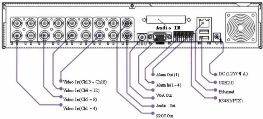
✿ Basic connections
1. Connect Cameras
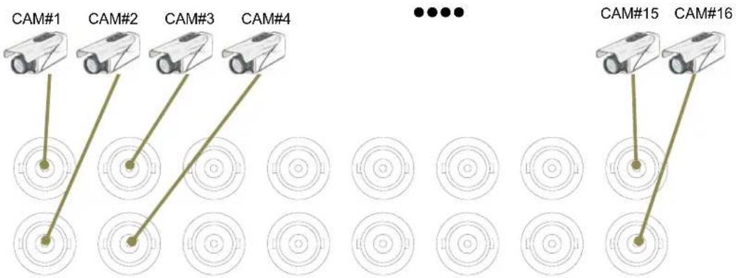
- Connect display devices
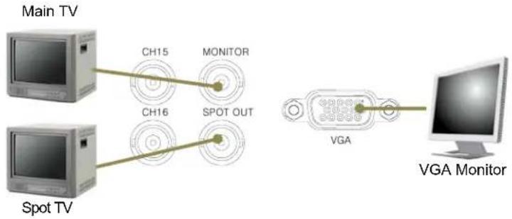
flowchart
graph LR
    A["Main TV"] --> B["CH15"]
    A --> C["CH16"]
    D["Spot TV"] --> E["SPOT OUT"]
    F["VGA"] --> G["VGA Monitor"]
Connect audio devices
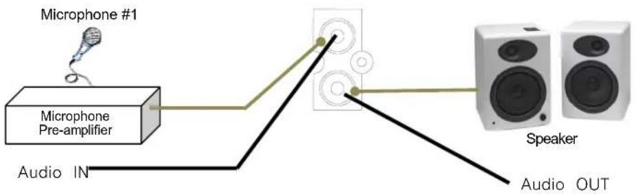
flowchart
graph LR
    A["Microphone #1"] --> B["Microphone Pre-amplifier"]
    B --> C["Speaker"]
    C --> D["Audio OUT"]
    B --> E["Audio IN"]
Connect alarms
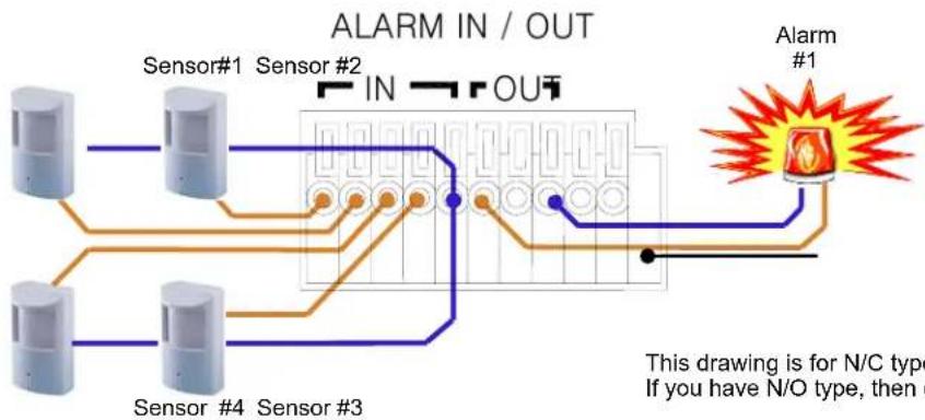
flowchart
graph TD
    A["Sensor #1"] --> B["IN"]
    C["Sensor #2"] --> D["IN"]
    E["Sensor #3"] --> F["OUT"]
    G["Sensor #4"] --> H["IN"]
    I["Alarm #1"] --> J["In"]
    style I fill:#f9f,stroke:#333
    note right of I: This drawing is for N/C type. If you have N/O type, then do.
This drawing is for N/C type device. If you have N/O type, then connect to N/O pin.
Connect RS-485 PTZ camera (optional)
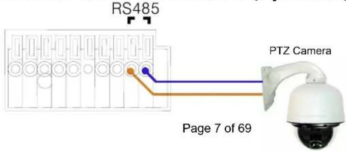
Connect to network

◆ Connect a mouse (optional)
The unit support hot plug-in & play.
Therefore, you can attach the mouse later, while the system is running.

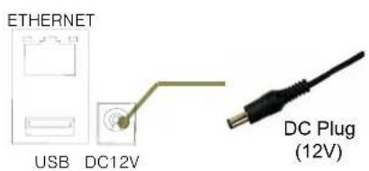
Connect power
TIME STAMP IS A VERY IMPORTANT REFERENCE FOR RECORDING AND SEARCHING. PLEASE, SET CLOCK CORRECTLY AFTER READING THIS SECTION.
Step 1. Set GMT/Location
Since DST rule is different location by location, you must set your correct location.
Please, set correct GMT/Location in Admin / DateTime menu.
◆ Refer to “Daylight Saving Time” section in Chapter 2.
◆ Refer to “Admin / DateTime” menu in Chapter 5.
Step 2. Initial time synchronization in Admin menu (Optional)
If the unit can access network time server, it is recommended strongly to synchronize the time with the network time server before start, in Service menu.
If the time difference is big, then time synchronization is failed in recording mode.
You can do this job in Admin / DateTime menu.
◆ Refer to Admin / DateTime menu in Chapter 5.
Step 3. Time adjustment
If you are unable to do step 2, then you need to adjust the time manually.
◆ Refer to Admin / DateTime menu in Chapter 5.
Step 4. Periodical time synchronization(Optional)
You can configure the unit to synchronize the time periodically with network time server.
◆ Refer to System / TimeSync menu in Chapter 4.
Chapter 2. Pre-acknowledgement
Front Panel

| key name | Descriptions | |
| Power LED POWER | Power indicator light indicates that DVR has power (including the shutdown state) | |
| Record LED REC | Shows status of recording | |
| Network LED NETWORK | Shows status of network | |
| IIDD-FULL LED | IIDD-FULL | Shows status of HDD-FULL. |
| POWER BUTTON | POWER | Shows status of power |
| Menu BUTTON MENU | Press to open the main menu. | |
| Esc BUTTON ESC | Press to close the main menu | |
| DISPLAY BUTTON | DISPLAY | Press to DISPLAY |
| REC BUTTON REC | Press to RECORD | |
| PLAY BUTTON | PLAY/PAUSE | Press to freeze playback to one frame, then press again to advance frame-by-frame |
| STOP BUTTON | Press to stop playback | |
| DIRECTIONG BUTTON | ▲.▼.◄.► | Press to move cursor up, down, left, and right |
| Reverse | ◄◄ | Press to reverse playback speed by 1/2, 1/4, 1/8 |
| FAST play | ►► | Press to increase forward playback speed 2X, 4X, 8X |
| ENTER BUTTON | ENTER | In menus, press to confirm selections |


Multiple unit with single remote controller
You can control multiple unit using single remote controller.
Each unit has its own Remocon ID, you can change/verify it in System / Info menu.
Ensure that each unit has different Remocon ID.
Please, follow below procedure to set a target unit among multiple units.
Step 1. Press ID button in remote controller.
If the unit in live view mode, "Remocon ID" message box will be displayed.
Step 2. Press two digit of the target unit's Remocon ID.
Pressed digit will be shown in "Remocon ID" message box. If you want to cancel the job, press ESC button.
Mouse operations
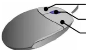
The unit supports PS/2 wheel mouse; hot-plug and play is supported.
natural_image
Illustration of a computer mouse with a blue cursor and black control points (no text or symbols)Left : Select
Note 1. Mouse is not supplied as an accessory.
- Support wheel mouse only.
- Double click is not supported.
Virtual keyboard
In some menus, virtual keyboard served for text entry.

Login

Default password for all account is "11111111" (eight digit of '1').
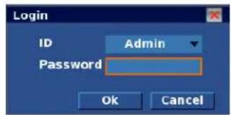
When you try to access some functions, the unit will display login window, and you have to login with proper permission to access the unit.
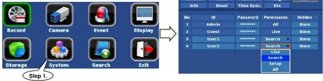
Entering User menu
Step 1. Press Menu button, and select System menu.
Step 2. Select User tab in System menu.
flowchart
graph LR
    A["Record"] --> B["Camera"]
    B --> C["Event"]
    C --> D["Display"]
    E["Storage"] --> F["System"]
    F --> G["Search"]
    G --> H["Exit"]
    I["Step 1."] --> J["Information Panel"]
    J --> K["Info"]
    J --> L["Email"]
    J --> M["Time Sync."]
    J --> N["Etc"]
    K --> O["No"]
    K --> P["ID"]
    K --> Q["Password"]
    K --> R["Permission"]
    K --> S["Hidden"]
    K --> T["1"]
    K --> U["Admin"]
    K --> V["**********"]
    K --> W["All"]
    K --> X["None"]
    K --> Y["2"]
    K --> Z["Guest"]
    K --> AA["**********"]
    K --> AB["Live"]
    K --> AC["None"]
    K --> AD["3"]
    K --> AE["User1"]
    K --> AF["**********"]
    K --> AG["Search"]
    K --> AH["None"]
    K --> AI["4"]
    K --> AJ["User2"]
    AJ --> AK["**********"]
    AK --> AL["Search"]
    AK --> AM["None"]
    AK --> AN["Live"]
    AK --> AO["Search"]
    AK --> AP["Setup"]
    AK --> AQ["All"]
ID
You can rename from User1 to User15 using virtual keyboard, other ID are pre-fixed.
Password
You can change the password, but be advised that you must delete old password using the backspace key of the virtual keyboard. 1 \~ 8 digits are possible as a password.
Permission
4 permission levels are available from User1 to User18; other user's permissions are pre-fixed.
■ Live : Right for live view only.
- Search : Right for live view and Search.
- Setup : Right for live view and Setup.
- All : Right for live view, Search and Setup.
Hidden
Administrator can assign different right to live view for each user.
In other words, all user could be assigned different "Hidden Camera" settings.
The unit is embedding world DST rules, and it is always enabled.

DST vs. Location
DST rule totally depends on your location.
Please, set correct GMT/Location in "Service: DateTime" menu.
"Service: DateTime" means DateTime menu in Service menu.
Effects of daylight
Time returns to one hour later at the end of DST, this means one hour recording data has the same time stamp. The overlapped zone (B) could be handled optionally. Refer to each menu descriptions in Chap 3. and Chap 4.

- Playback : The unit playback zone (A) and zone (B) are both continuously.
- Calendar Search : You can address exact time point in zone (B).
- Event Search : You can limit search range to zone (B).
- Backup : You can limit backup range to zone (B).
Updating DST rule
Once your location's DST rule is changed, then you need to upgrade firmware. Otherwise, the last DST rule or no rule will be applied.
If you cannot upgrade firmware, we recommend to do followings;
- Backup : Do backup prior to adjusting system clock backward.
Otherwise, the overlapped data (zone (B)) will be destroyed.
- Clock adjustment : Adjust system clock in Service::DateTime menu.
Shutdown (Auto power off)
Since the HDD contents could be damaged when HDD power is removed while accessing the HDD, it is strongly recommended to follow shutdown procedures.
Step 1. Shutdown in menu
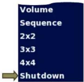
The unit prepares to shutdown when you choose
Shutdown in Quick menu.
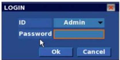
Then login message box appears
Enter 'Admin' password.
Step 2. Auto power off
The following appears "Do you want a shutdown?" message.
If you choose "Yes" then system is powered down

Chapter 3. Operation
View panel


Camera pane

You can show/hide the below items in Display::Screen menu.
- Camera name

It shows camera name which is configured in Camera::Setup menu.
- Audio

It shows when you enable the audio function in Camera::Setup menu.
- Recording mode
It shows recording mode which is configured in Record::Schedule menu.

Normal mode

mode

Alarm mode

Motion mode
- Event status
It shows when some events are detected and recording has started.
There is no status in Normal mode.

Motion event

Alarm event

Motion and Alarm event (Both events are detected at same time)
Status bar
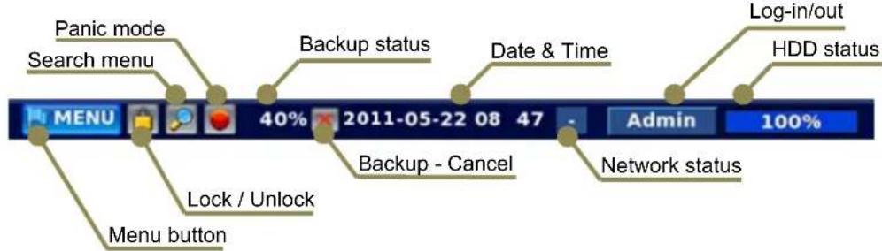
- Menu button

Click this button to access Menu panel.
- Lock/Unlock
Click this button to Lock/Unlock mouse and front panel button operations.

Locked

Unlocked
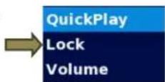
Also, you able to locked through Quick menu.
- Search Menu

Click this button to enter into Search menu.
- Panic mode
When you press this button it starts to record immediately at any condition.
Login is required to stop Panic mode.

c mode
Normal mo

- Backup status

It indicates that backup is in progress and its progressive rate in percentage.
- Date & Time 2011-05-22 08 47
It shows current date & time in "YYYY-MM-DD HH:MM" format.

Auto clock available through public network time server on internet.
See System::Time Sync. Menu in chapter 4. to use auto clock.
- Network status

It shows count of network connection such as Web viewer and CMS.
“-” means that network is disconnected.
- Log-in/out

It has two functions as below.
1) Log-in/out button
Click to log-in (or log-out) to(from) the unit.
2) User information
It shows log-in user name.
See System::User menu in Chapter 4. for user management.

Auto-hiding of status bar & Playback control bar
In the auto-hide mode, the status bar and playback control bar are shown/hidden automatically. You can change the mode in Display::Screen menu.
1) Shown
- When mouse pointer is moved to bottom area of the screen.
- When Menu button is pressed in front of panel or remote controller.
2) Hidden
It is hidden when above "Shown" condition is removed, and Show time is passed.
Panic mode (emergency recording)
The unit supports Panic mode for instant recordings in emergency situations.
You can start Panic mode whenever you want.
To stop Panic mode, you need to log-in with "Setup" permission account.
- Start Panic mode with remote controller
Press REC button.

- Start Panic mode with mouse
Click PANIC icon.

◆ Single-screen display
You can watch a single camera in full screen mode.
- Front panel 'SCREEN' button when you click the continue button.
Camera number increases in full screen mode.
Remote controller Press a number button that you want to watch.


Selecting channels over 10
Follow below procedures to select from ch11 to ch16.
Step 1) Press "+10" button.
Step 2) Press "1".
In this case channel 11 will be selected.
- Mouse
Step 1) Move pointer to a pane you want to watch in single screen.
Step 2) Click Left button.

◆ Multi screen display
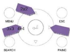
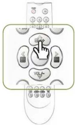
The unit support multi screen display mode such as 2x2, 3x3 and 4x4 divisions.
-
Front panel & Remote controller
-
2x2 division : Press Up button
- 3x3 division : Press Left button
- 4x4 division : Press Right button

- Mouse
Click Left button at any location on the screen.

- Quick menu
Click Right button and the quick menu appear.
- 2x2 division : Click 2x2
- 3x3 division : Click 3x3
- 4x4 division : Click 4x4

Page 22 of 69
◆ Audio volume control
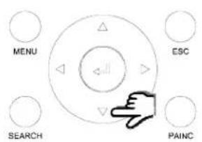
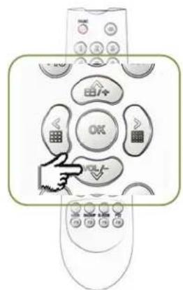
There are two ways to control audio volume and muting.

1. Using Volume button
Press "VOL" button, then Volume control menu will be shown.
■ Volume up : Press Up (+) button
■ Volume down : Press Down (-) button
- Mute : Move focus to "Mute" using Left/Right buttons,
and press OK button.
2. Using Quick Menu
1) Right click on mouse button, and Quick menu appears.
2) Press "OK" button in front panel or remote controller, then Quick menu appears.
Select Volume menu and press "OK" or click Left button of the mouse, then Volume control menu appears.

PTZ (Pan / Tilt / Zoom) (Single screen mode only)
This facility works in following conditions;
- PTZ camera is connected to the desired channel.
- Model and Setting are correct in Camera::PTZ menu.
- RS-485 bus is working properly.
1. Entering into PTZ mode
1.1 Press PTZ button in remote controller.
1.2 Use Quick menu.


2. PTZ control panels
2.1 On screen control panel (GUI)
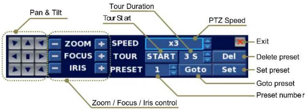
2.2 Key board control(Optional)
3. Pan & Tilt
It is same manner you use GUI or remote controller.
- Choose a desired direction button you want to move.
- To stop moving, press Stop button.
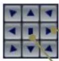
Direction button
Stop button
4. Preset
4.1 Set a new preset point
Step 1) Move to a desired point you want to store as a preset using direction buttons.
Step 2) Assign an any preset number.
Step 3) Press "Set" button.

flowchart
graph LR
    A["1 Grid"] --> B["2 Speed x3"]
    B --> C["3 S Del"]
    B --> D["1 Goto Set"]
    C --> E["3 Goto Set"]
4.2 View a preset point
Step 1) Choose an any preset number you want to watch.
Step 2) Press "Goto" button.
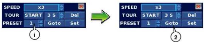
flowchart
graph LR
    A["SPEED x3"] --> B["TOUR START 3 S Del"]
    B --> C["PRESET 1 Goto Set"]
    D["SPEED x3"] --> E["TOUR START 3 S Del"]
    E --> F["PRESET 1 Goto Set"]
4.3 Delete a preset point
Step 1) Choose an any preset number you want to delete.
Step 2) Press "Del" button.

flowchart
graph LR
    A["SPEED x3"] --> B["TOUR START 3 S Del"]
    B --> C["PRESET 1 Goto Set"]
    C --> D["→"]
    D --> E["SPEED x3"]
    E --> F["TOUR START 3 S Del"]
    F --> G["PRESET 1 Goto Set"]
    G --> H["2"]
Search & Playback
Two playback tools are served as below;
1) Quick Play : Instant playback in live mode, start from 10 minutes ago.
2) Search menu
There are two search options;
- Calendar search : Specific date & time is used as a playback start point.
- Event Search : Motion or alarm event point is used as a playback start point.
◆ Playback Control
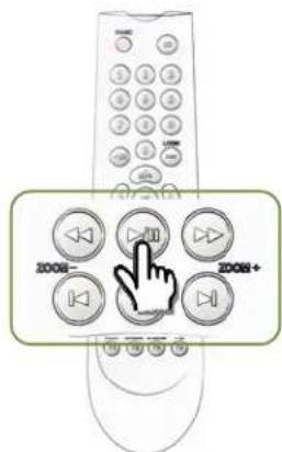
You can control playback using 3 control tools Front panel, Remote controller and GUI.
| Function | Front Panel | Remote Controller | GUI (Mouse) | Remark |
| Fwd. Play - | [A5KZ] |  | Quick play | |
| Rev. Play - |  |  | ||
| Pause - | Keep playback speed. |  | ||
| Stop | - |  speed to x1. speed to x1. | ||
| Next Frame | - |  |  | Playback frame by frame. |
| Prev. Frame | - |  |  | |
| Fast Fwd. Play | - |  |  | Playback speed is changed from x1 to x64 when press play button. |
| Fast Rev. Play | - |  |  | |
1. Remote Controller
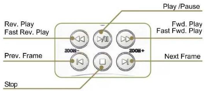
2. GUI
◆ Quick play
Quick play offers convenient playback in live view mode, it starts to play from 10 minutes ago.
Press Q-PLAY button in front panel or remote controller.
The unit is switched into playback mode immediately with "QuickPlay" pop-up message box.
Choose "QuickPlay" in Quick menu.

◆ Sequence & screen separate
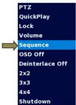
Sequence offers rotation screen by single screen mode, 2x2 screen mode or 3x3 screen mode. If you want duration time changed where the setting duration time in display menu.
Click sequence and "Seq" icon will appear on the top right by live screen.
Clicking the sequence again will disappear.
"Seq" icon and rotation stop.
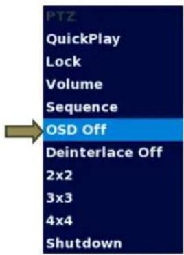
OSD On/Off
OSD Off offers the onscreen OSD is all disappear.
Then OSD Off item changed OSD on.
When you click the OSD on the OSD will appear.
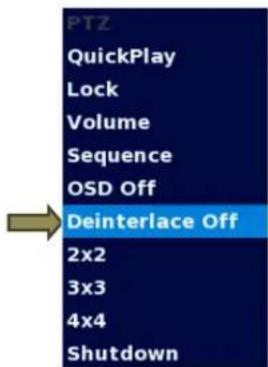
◆ De-interlace On/Off
Deinterlace Off offers the Deinterlace mode off.
When Deinterlace Off item changes to Deinterlace On.
When you click the "Deinterlace On" the Deinterlace mode on.
◆ Entering to search menu
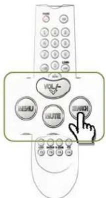
1. Front panel & Remote controller
Press SEARCH button on remote controller, then a menu panel will be displayed.
2. GUI (Mouse)
Click Search icon in the status bar.

◆ Calendar Search
Calendar search mode is a default mode.
If you are in Event mode, then choose "Calendar" tab to switch to Calendar mode.
Step 1. Choosing a date
You can choose one of red colored dates.
Black colored dates have no recording data.

Step 2. Choosing an hour
Recording map will be shown in an hour unit.
The color on the map is indicating recording mode as below.
- Red : Normal Recording
- Blue : Motion event
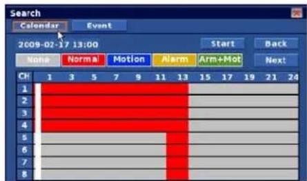
- Yellow : Alarm in event
- Green : Two events at same time - Alarm in event & Motion event
You can start to playback by pressing "Start" button or back to step 1. By pressing "Back". To choose a minute, press "OK" in the recording map.
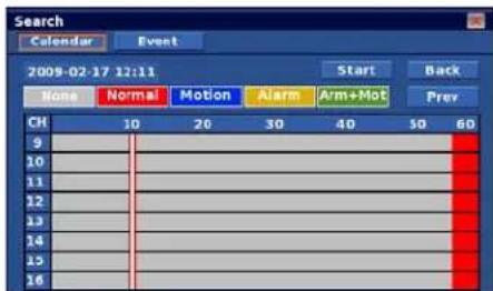
Step 3. Choosing a minute & Play
Recording map will be shown in a minute unit.
You can start to playback by pressing "Start" button or back to step 1. By pressing "Back".
Pressing "OK" in the recording map will also start to play.
Step 4. Playback Control & Return to search menu
- See "Playback Control" section above for playback control.

- Return to search menu
There are two ways to return to search menu from playback mode.
1) Press "ESC" in front panel or remote controller
2) Click ✗ icon on playback control bar to quit playback mode.

Daylight in calendar search mode
Please, read "Daylight Saving Time (DST)" section first.
Daylight button will be shown if the selected date is including zone (A) and (B).
This button is useful when addressing start point in Zone(B).
The recording map will be updated when you press Daylight button.
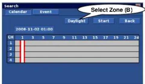
Event Search
Step 1. Select "Event" if you are in Calendar mode.
Step 2. Select desired channel to search.
Step 3. Set start date & time to search.
Step 4. Set stop date & time to search.
Step 5. Check event type to search.
Step 6. Click Search, event list will be displayed.
Step 7. Choose one event that you want to play.


Daylight in event search mode
When this option is checked, searches range is limited to zone (B).
At this point, zone (B) must exist within your selected range in Step 6 & 7.
You can backup recording data to USB storages or built-in optical storage.
◆ Backup device
■ Built-in CD/DVD (option)
- USB Flash / HDD / CD / DVD (Support USB 2.0 devices only.)
◆ Backup file type
- Native DB (Database)
This type is a unique format for video recording.
You can play this format using Backup viewer only.
Native DB does not support individual channel backup.
AVI
This type is an industrial standard AVI file.
Be advised that some media players do not support H.264 AVI file.
It is recommended to use MPlayer for audio playback.
- MPlayer : Visit http://www.mplayerhq.hu to download.
Try GOM player if you need another free player, but it does not support audio decoding.
- GOM Player : Visit http://www.gomlab.com/eng/ to download.
It supports English, Chinese, Japanese, and Korean.
❖ Entering Backup Menu
Step 1. Press Menu button, and select Storage menu.
Step 2. Select Backup tab in Storage menu.

flowchart
graph LR
    A["Step 1."] --> B["Storage"]
    B --> C["60 °C Enable"]
    C --> D["Device Capacity Type Format S.M.A.R.T. Temperatur SATA-1 500GB Data N.A."]
    style A fill:#99ccff,stroke:#333
    style B fill:#f9f9f9,stroke:#333
    style C fill:#fff,stroke:#333
    style D fill:#fff,stroke:#333
    note right of B Step 2.
    note right of A: Step 1.
Backup
Step 1. Try "Refresh" if the backup storage is not shown in the Device list.
Step 2. Choose a backup device in the list.
Available capacity will be shown.
"Total:4.5 GB (8 MB)" means that
Total media capacity is 4.5GB, and remaining capacity is 8MB.
Step 3. In the case of CD-RW or DVD-RW,
Erase button will be enabled.
You can erase the media using this button.
Step 4. Choose a backup file type between
"Native DB" and "AVI".
![Storage Storage S.M.A.R.T. R 1 Backup 12 Device [CD-1] DVD-RAM GH22N530 Refresh Capacity Total:4.5 GB(4.5 GF) Erase Channel All Type AVI Daylight Start Time -10 -01 -14 19 : 22 : 44 End Time -10 -01 -14 20 : 22 : 44 Search Data Size 2.5 GB Start 9 10 Tip](/content/2026/05/1066911/images/4b49131a3088e7f270343649022eb7915f43822491a3b708ffaa20ecfe03cb79.jpg)
Step 5. In the case of AVI type, you can select specific channel to backup.
Step 6 & 7. Set start/End date & time to backup.
Step 8. Click Search button to search available backup data.
Step 9. Total backup file size is shown in this column.
Step 10. Click "Start" to start to backup.
Step 11. Click "Open" on CD-RW or DVD-RW tray to open.
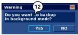
Step 12. Choose a backup mode between background mode and normal.
Note that the backup time is same between two backup modes.
- Choose YES for background mode.
The unit will return to live view mode, and backup will start.
In this mode, backup status is shown in Status bar.
Backup status in background backup mode Backup status in background backup n

- Choose NO to start to backup immediately.
Choose CD or DVD, then "Burning..." message will be shown.
Otherwise, "Writing..." message will be shown.


[CD/DVD] [Other storage]

Daylight in backup
When this option is checked, the unit searches recording data in zone (B).
At this point, zone (B) must exist within your selected range in Step 6 & 7.
Chapter 4. Setup
Press or click Menu button in front panel or status bar to open menu panel.
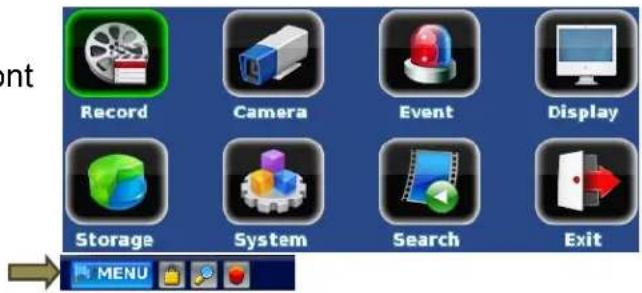

Menu naming rule
For example, "Record: Setup" is indicating
Setup menu in Record menu.
(Record menu is a root menu, and Setup menu is a sub-menu)
Summary
- Record
- Image size settings / Frame rate settings / Schedule edit / Holiday settings
- Camera
- Camera naming / Audio on/Off / Color control
Event
- Alarm In & Out settings / Email report settings / Buzzer settings
- Display
- Camera pane layout control / Status bar control - Spot output settings
- Storage
- Storage view / Formatting / S.M.A.R.T. view / Writing settings / Backup
System
- Network & Server settings
- Log view & save to USB storage
- User management
- View DVR information: Remocon ID, F/W & Kernel version, MAC address
- Gateway to Service menu
- Time synchronization
- Email settings
◆ Record - Setup
Size
Move to Size column, and press OK, then available image size will be shown. Note that all channels are using same image size.

- NTSC : 704x480(D1) / 704x240(HD1) / 352x240(CIF)
- PAL : 704x576(D1) / 704x288(HD1) / 352x288(CIF)
fps (recording frame rate)
Available frame rate are listed by image size.
- NTSC : 30 / 15 / 7.5 / 3.75 / 1.88
- PAL : 25 / 12.5 / 6.25 / 3.125

D1 real time recording
You can record D1 (704x480) size image in real time (120Frames/sec) when 4 cameras are connected to the system.
Quality
High quality means shorter recording time, because the compression file size is getting bigger and bigger when you choose more high quality levels. 5 quality levels are available.
- Best / High / Medium / Low / Lowest
Pre (Pre alarm duration)
Pre alarm duration is fixed as two options: None and 5 seconds.
Post (post alarm duration)
Six post alarm duration times are available: None / 3 / 5 / 10 / 20 / 30 sec
◆ Record - Network
Size
Image size is dependent on the record size
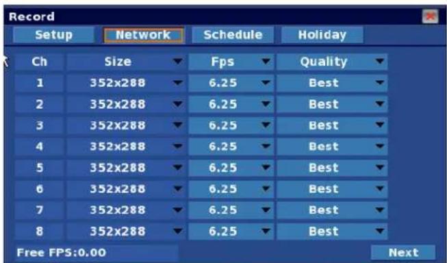
- NTSC : 704x480(D1) / 704x240(HD1) / 352x240(CIF)
- PAL : 704x576(D1) / 704x288(HD1) / 352x288(CIF)
Fps (network transmission frame rate)
Available network transmission frame rates are listed by image size.
- NTSC : 30 / 15 / 7.5 / 3.75 / 1.88
- PALT : 25 / 12.5 / 6.25 / 3.125
Quality
High quality means shorter recording time, because the compression file size is getting bigger and bigger when you choose more high quality levels. 5 quality levels are available.
■ Best / High / Medium / Low / Lowest
◆ Record - Schedule

Recording Mode
- Normal : Red, Record continuously.
- Motion : Blue, Start recording by motion event.
See Camera:: Motion menu to configure motion event.
- Alarm : Yellow, Start recording by alarm event.
See Event:: Alarm in menu to configure alarm event.
- Alm+Mot : Green, Start recording by motion event or alarm event.
Scheduling
Step 1. Select Schedule tab to switch to Schedule menu.
Step 2. Select start point to assign.
You can select any day of the week, any hour, and holiday.
See Recording::Holiday to assign holiday.
Step 3. Select stop point.
Step 4. Select a recording mode.
(Alarm is selected in the example.)
Step 5. Desired zone is changed into yellow color (alarm mode).
◆ Record :: Holiday
You can assign your holidays for 2 years.

Add a new holiday
Select a date and press OK, the date will change into red, holiday.
Delete a holiday
Select a desired holiday and press OK, the holiday will change into black, working day.
Delete all holiday
Press "Clear All" button to delete all holidays of two years assigned by user.
◆ Camera - Setup
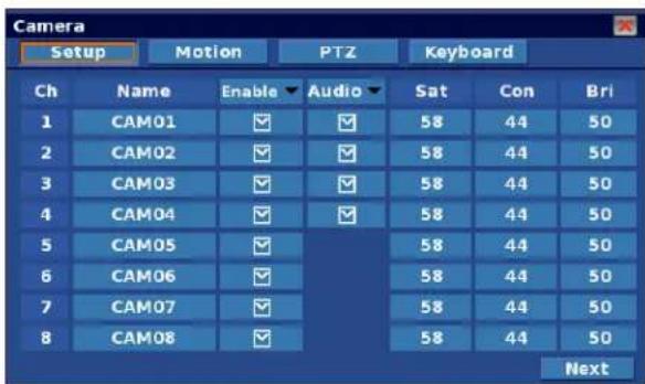

Name
You can change the camera name using virtual keyboard.
Press OK to show virtual keyboard.
Enable
Enable or disabling the channel.
Note that Ch. 1 should be turned on always.
Audio
Check this option if you attach a microphone to the channel.
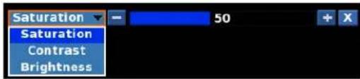
Sat / Con / Bri
You can adjust color settings using this menu.
◆ Camera - Motion
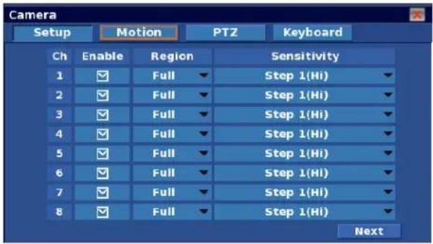
Enable
It enables motion event.
Region
Motion detection cells consist of 15x15 cells.
You can enable or disable each cell.
- Full : All cells are enabled.
- User : You can configure each cell.
Sensitivity
Five levels of motion detection sensitivity available, from step 1 to step 5.
Camera - PTZ
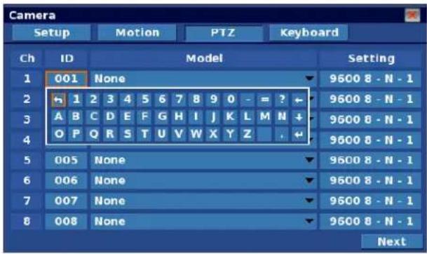
ID
It is a RS-485 device address.
You must set a address if PTZ camera is attached.
Available range is from 1 to 255.
You can change the PTZ camera ID using virtual keyboard.
Press OK to show virtual keyboard.
Model
You can choose a PTZ camera model or protocols.
Settings
You can configure RS-485 communication settings.

[Settings]
Event - Alarm In
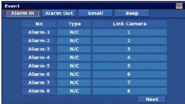
Type
You can configure the alarm device's output polarity.
- N/C : Normal Close
- N/O : Normal Open
Link Camera
The linked camera starts to record when alarm event is detected.
Event - Alarm Out

Alarm Out Number?
Set the alarm out number you want to configure.
Duration
You can set alarm output durations up to 30 seconds.
- None / 3 / 5 / 10 / 20 / 30 seconds
Motion
If box checked, Alarm output will be turned on when motion event is detected on the selected channels
Video Loss
If box checked, Alarm output will be turned on when video loss event is detected on the selected channels
Alarm In
If box checked, Alarm output will be turned on when the camera records by alarm during event. It is reflecting "Link Camera" settings in the Event - Alarm in menu.
For example,
- Settings
- Camera-1 is linked to Alarm In #1 and Alarm In #2 in Event-Alarm In menu.
- Alarm In of Camera-1 is checked in Event-Alarm Out menu.
Action
Alarm out is turned on when Alarm #1 and/or Alarm #2 event is activated.
Event - Email
Configure email settings in System-Email menu to use this service.
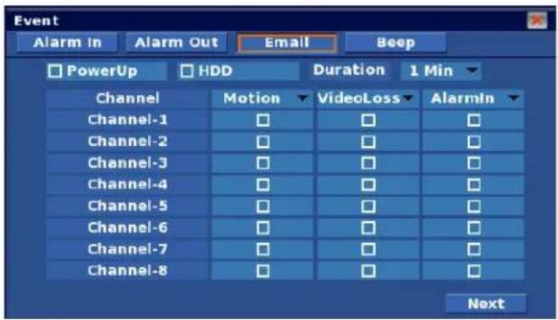
Power Up
If box checked, Email is sent when power is turned on.
HDD
If box checked, Email is sent when HDD event occurs.
Motion
If box checked, Email is sent when motion event is detected on the selected channels.
Video Loss
If box checked, Email is sent when video loss event is detected on the selected channels.
Alarm In
If box checked, Email is sent when the camera records by alarm during event. It is reflecting "Link Camera" settings in the Event - Alarm in menu.
Event - Beep
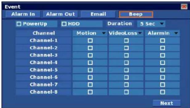
Power Up
If box checked, buzzer beeps when power is turned on.
HDD
If box checked, Email is sent when HDD event occurs.
Duration
You can set alarm output durations up to 30 sec.
- None / 3 / 5 / 10 / 20 / 30 seconds
Motion
If box checked, Email is sent when motion event is detected, on the channels selected.
Video Loss
If box checked, Email is sent when video loss event is detected, on the channels selected.
Alarm In
If box checked, Email is sent when the camera records by alarm during event. It is reflecting "Link Camera" settings in the Event - Alarm in menu.
◆ Display - Settings

Camera name
It shows a camera name on the camera pane.
Record mode
It shows record mode and status on the camera pane.
Audio record icon
It shows audio record icon on the camera pane.
Status bar auto-hide
Status bar will be hidden automatically if this option is enabled.
To watch status bar, you can do one of the following: move the mouse pointer to bottom of the screen; press OK, use the menu in the front panel, or use the remote controller. You can set show-time of the status bar from 1 to 10 seconds.
This configuration is applied to the playback control bar also.
To see the playback control bar, move the mouse pointer to bottom of the screen, press playback control button in front panel menu, or use remote controller.
Sequence
If checked it will enable main screen rotation. You will be able to set a duration time.
Press combo box to show virtual keyboard.
Alpha blending
Menu box will be similar transparency if this option is enabled.
In Alpha blending mode, you can choose a value
- Opaque/ Low / Medium / High.
◆ Display - Spot
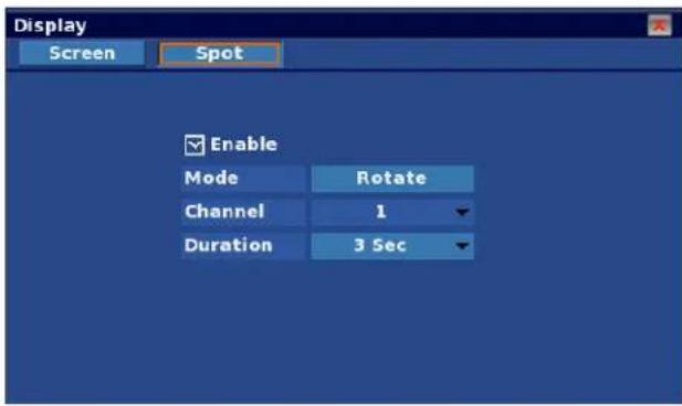
Enable
Clicking the box enables spot operations.
Mode
There are two mode options: Fixed and Rotate.
Channel
In Fixed mode, you need to choose a channel you want to watch.
Duration
In Rotate mode, you can choose a duration option from the list below:
3 / 5/ 10 / 20 / 30 seconds.
◆ Storage - Storage

Temperature Limit
HDD event occurs when HDD temperature exceeds this limit.
Enable
Clicking the checkbox enables HDD temperature limit event.
Refresh
It updates storage information. It is useful when you attach USB storage.
Device / Capacity
It shows storage types and its capacity.
Internal SATA storage is shown as SATA-{number} device.
Format
This button is enabled when USB storage is attached.
You can format the storage using this button.
S.M.A.R.T. (Self Monitoring Analysis and Reporting Technology)
It shows HDD health using S.M.A.R.T.
Temperature
It shows current HDD temperature using S.M.A.R.T.
◆ Storage - S.M.A.R.T.

- Use S.M.A.R.T information for reference purpose only.
It does not indicate exact HDD conditions.
- Some old or new HDD could show correct S.M.A.R.T. information.
![Storage Storage S.M.A.R.T. Record Backup FTP Device [SCSI-1] WDC WD3200AAKS-00YGAO 44 °C IDwerthAttribute Value Worst Threshold 1 Raw Read Error Rate 200 200 51 5 Reallocated Sector Ct 200 200 140 10 Spin Retry Count 100 100 51 196 Reallocated Event Count 200 200 0 197 Current Pending Sector 200 200 0 198 Offline Uncorrectable 200 200 0](/content/2026/05/1066911/images/c20cd1c415ac09604de1205983cd8ebd9a4259076b5eb3f5dd0e8b6b95fe52c5.jpg)
Device
It shows the storage information.
ID
It is an index of the S.M.A.R.T. register.
Attribute
It is an attribute of the HDD.
Value
It is a current monitoring status.
Worst
It is a smallest value of the attributes.
Threshold
It is a limitation which it is assigned by HDD manufacturer.
If the Value is close to or lower than the threshold value, then the HDD may has some problems.
◆ Storage - Record
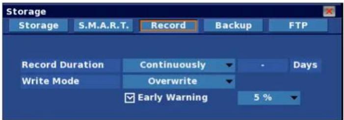
Record Duration
You can configure Record time using the options below:
- Continuously
30 / 60 / 90 days - User Defined
Write Mode
There are two mode options.
- Overwrite: Old data on the HDD will be erased when the HDD is full.
- Suspend: Recording is stopped when the HDD is full.
Early Warning
HDD warning will be issued if remaining HDD capacity is less than the selected limit. From 5% to 30% are available.
◆ Storage - Backup
![Storage Storage S.M.A.R.T. Record Backup Device [USB-1] CD/DVDW SE-T084L Refresh Capacity Total:4.5 GB(8 MB) Erase Channel All Type Native DB Daylight Start 2008 - 06 - 18 12 : 51 : 45 End 2008 - 06 - 18 13 : 51 : 45 Search Data size 128 MB Start](/content/2026/05/1066911/images/ed143b7c6b2e5388519c774822f1a834721cdf4ae69390b7094d8ee0410e237c.jpg)
◆ Refer to "Backup" section in Chapter 3. Operation.
System Settings
◆ System - Network

DHCP
Check this option if you will not using fixed IP.
The unit requests an IP as soon as you save and exit the menu.
You can verify the IP address and other network configurations in this menu after a few minutes.
If the network condition is good, the unit can get IP address within a couple of seconds.
If you are not using DHCP, you have to fill all information manually.
Obtain details about the Network information from your ISP or network administrator.
◆ System - DDNS
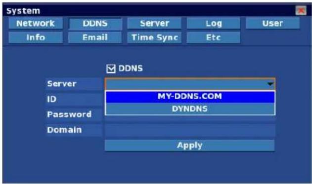
DDNS
Check this box to enable Dynamic DNS function. You can choose from one of two DDNS options.
1) DNIP.NET : Public DDNS (Registration is required.)
2) MY-DDNS.COM : Closed DDNS (Registration is not required, Exclusive for this DVR)
MY-DDNS.COM
This exclusive DDNS is very easy to use. Simply assign a domain name and click Apply.
Step 1) Check DDNS option box.
Step 2) Choose MY-DDNS.COM
Step 3) Enter a name in the Domain[my-ddns.com] column.
Step 4) Click the Apply button, a Success Message box will be shown.
![System Network DDNS Server Log User Info Email Time Sync.Etc 1 2 DDNS Server MY-DDNS.COM ID Password Domain[my-ddns.com] Apply](/content/2026/05/1066911/images/0955f7059252f6819f67f5d0a5a9099eaeff7ce87b4e88e62bb4133052e8e4e4.jpg)
DYNDNS
This is a public DDNS, registration is essential.
Step 1) Register (sign-up) on the web.
Currently, we support DNIP.NET, a free service.
You will need to sign-up at www.dyndns.com to get a User ID and password.
You will need to configure "port forwarding" if you are using a router.
Visit http://www.dyndns.com/ for details.
Add New Hostname
Note: You currently don't have any active Dynamic DNS Pro upgrades in your account. You cannot use features. Paying for an Dynamic DNS Pro upgrade will make this form fully functional and will add sex
![Hostname: dvr . dvrdns.org Hostname not given. Wildcard Status: Disabled [want wildcard support?] Service Type: Host with IP address [?] WebHop Redirect [?] Offline Hostname [?] IP Address: 218.54.186.86 Use auto detected IP address 218.54.186.86. TTL value is 60 seconds. Edit TTL. Mail Routing: Yes, let me configure Email routing. [?]](/content/2026/05/1066911/images/b0f35b8ce1b652307151a32ae3e4455c98be3094a634785193f6bbee58876733.jpg)
[ DYNDNS sign-up screen ]
Step 2) Check the DDNS option box.
Step 3) Choose DYNDNS
Step 4) Enter the User ID and password that you registered with at www.dyndns.com
Step 5) Click the Apply button, a Success Message box will be shown.

◆ System - Server
Unit Network Settings are shown in this menu.
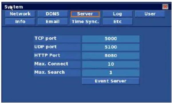
TCP / UDP / HTTP port
These ports are fixed to 5000, 5100 and 8080; this is used for CMS and Web viewer service.
Max. Connect
This value is the limit of the total number of network connections for live viewing. System could be unstable if the number of connections is higher.
Max. Search
This value is the limit of total number of network connections for search.
Because searching requires excessive system resources, a higher search value could cause unstable operation.
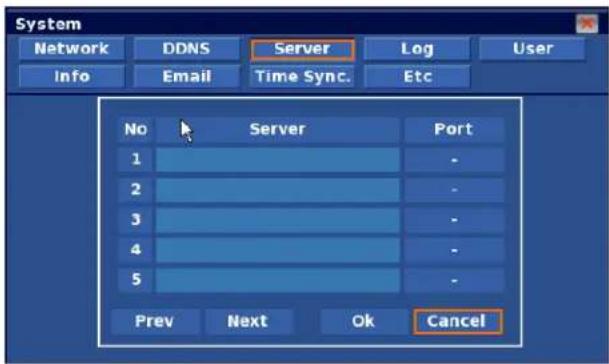
Event Server
Press "Event server" button, the Server list box will appear.
The server list shows received server information from event data by CMS host.
◆ System - Log
You can verify history of the system operation using the Log Menu.
![System Network DDNS Server Log User Info Email Time Sync Etc Type All Descending Start 2010 - 01 - 14 20 : 31 : 09 End 2010 - 01 - 14 20 : 45 : 09 [Admin] 2010-01-14 20:33:26 Setup finished. [Admin] 2010-01-14 20:35:18 Setup start. [Admin] 2010-01-14 20:38:53 Setup finished. [Admin] 2010-01-14 20:38:56 Setup start. [Admin] 2010-01-14 20:43:04 DDNS success. Search Save](/content/2026/05/1066911/images/f54cad70a9124780afc970589209527e75427d21a934aee2b05663301e89310f.jpg)
Type
You can choose a type of history such as System, Setup, Search, etc.
Start / End
You can set the Search Range using this Drop Down Menu.
Search
Search will begin as soon as the Search button is clicked.
Save
You can save the log data using USB storage. File name is fixed to "log.txt".
System - User

◆ Refer to the "User management" section in Chapter 2. Pre-acknowledgement.
System - Info
![System Network DDNS Server\Log User Info Email Time Sync Etc Name DVR Remocon ID 00 Firmware Version 1.0.0 [Jan 14 2010 18:23:55] Kernel Version 1.0.0 MAC Address 00:22:E8:00:00:03 Admin Menu](/content/2026/05/1066911/images/6d01a13f69180bbafd91be22005e158c169d015f07b7fe2d348e62f447a9d5ec.jpg)
Name
Name on network (CMS).
Remocon ID
Identification for InfraRed (IR) remote controller.
See "Infrared remote controller" in Chapter 2. Pre-acknowledgement.
Firmware Version
Firmware Version information.
Kernel Version
Kernel Version information.
MAC address
Identification of the unit on the network; it must be unique to prevent conflict on the network.
Service Menu/ Admin Menu.
You can switch to Service Menu through this button.
See Chapter 5. Service menu for details.
System - Email
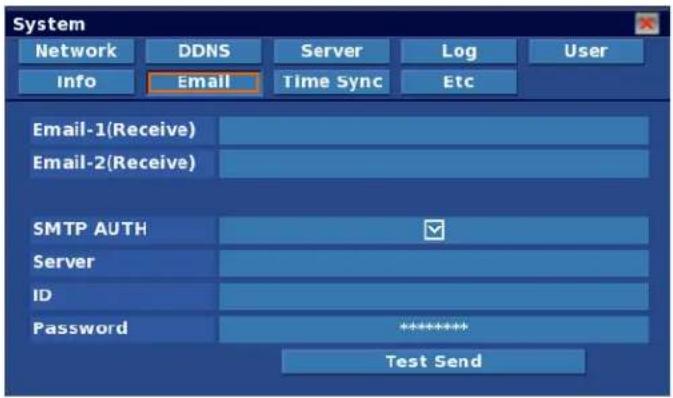
Email-1 (Receive)
Primary receiver's email address.
Email-2 (Receive)
Secondary receiver's email address.
SMTP Auth
Use for SMTP Authentication.
Server
IP address or URL of SMTP server for sending emails
ID
Sender email account of the SMTP server.
Passowrd
Password of the sender account.
TestSend
Test Mail button will send a test email as soon as it is pressed.
◆ System - Time Sync.
Time Sync.
When the box is checked, the unit starts to synchronize the System clock with Network time server using NTP. NTP server offers the most reliable atomic clock.
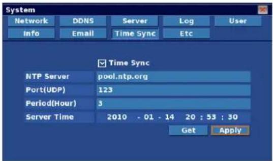
NTP Server
The unit will look for near network time server if you use "pool.ntp.org".
You can use other network time server if the default server setting has some problem.
Port (UDP)
It is an NTP Server port fixed by network time server.
Period (Hour)
The unit synchronizes the clock periodically; you can set the Period in hour units.
Server Time
It shows the time offered by Network Time Server when you press the Get button.
Get
When the Get button is clicked, the unit will try to get a time from the Network Time Server. Server Time will be updated if there is no problem.
Apply
Once you have found and made the changes, click on the Apply button to complete the changes made to current system time using Network Time Server in the "Time Synchronization" tab.

Failure of time synchronization
If time difference is significant, Failure Message will appear.
In this case, you need to try Time Sync. In the Service / DateTime menu.
If system time is faster than the Network Time Server's time, then it is recommended to backup recent data. Otherwise, it will be erased.
System - Etc

Key Beep
Buzzer beeps when front panel button or remote controller button is pressed.
You have the option to enable or disable this feature.
Temperature Unit
You can choose the Temperature display unit between Celsius degree and Fahrenheit degree.
Auto-Logout
It enables Auto-Logout operations.
In Auto-Logout operations, you can adjust the duration using the virtual keyboard.
Duration is adjustable from one to sixty minutes; by one minute units.
VideoMode
You can choose between two Video Modes: NTSC and PAL.
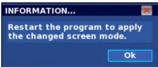
If you change the video mode, a warning window appears; Click OK.
VideoLoss Record
Video Loss will be recorded if you click on the Enable check box.
Chapter 5. Admin Menu
Entering the Service Menu
You can enter the Service Menu through System/Info/Admin Menu.

flowchart
graph LR
    A["Record"] --> B["Camera"]
    B --> C["Event"]
    C --> D["Display"]
    E["Storage"] --> F["System"]
    F --> G["Search"]
    G --> H["Exit"]

    I["Step 1."] --> J["Step 2."]
    J --> K["System"]
    K --> L["Info"]
    K --> M["Email"]
    K --> N["Server"]
    K --> O["Log"]
    K --> P["User"]
    K --> Q["Etc"]

    R["Step 3."] --> S["Admin Menu"]
Admin - Upgrade
![Service Upgrade Config Form DateTime Language Device [USB-1] SWING MINI Refresh Kernel 1.0.1 Firmware 1.0.1 Current Version Kernel 1.0.1 Firmware 1.0.1 Upgrade](/content/2026/05/1066911/images/5a19275d6c64fbb93c6147e654dee1f140335c4783bffe961f2f2dcc6b63ac53.jpg)
You can upgrade Kernel and Firmware using
USB storage at same time or separately.
Step 1: Choose the USB storage that contains the
Upgrade file. Press the "Refresh" button if there is no USB storage device.
Step 2: Press the "Refresh" button.
The unit will start to scan USB storage and show it's version.
Step 3: Press the "Upgrade" button to start the Upgrade.
Upgrade will take a couple of minutes.
Admin - Config
![Service Upgrade Config Format Datetime Language Device [USB-1] SWING MINI Refresh Factory Default Export Import](/content/2026/05/1066911/images/2b4726d4fd2fbd50928b81317302924d173dadfb00a187bde28e503ea5f05454.jpg)
You can export or import unit's configuration using USB storage.
- Factory default: Return to factory default settings.
- Export: Copy this unit's configuration file to USB storage.
You can find "Config.dat" in the USB storage. - Import: Copy configuration file from USB storage.
Admin - Format

Since recording is stopped, you can format any data disk in the Service menu. Press Format button on the GUI.
Admin – DateTime
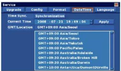
Time Sync.
You can adjust the System clock using the "Time Sync." menu.
Standard Time will appear as shown below when you press the "Sync" button.

Press "Sync." To adjust system clock to standard time which is read from network time server.
Current Time
System shows current system clock, which can be adjusted manually. Press "Apply" to accept changes to the system clock after adjustment.
GMT/Location
Assign correct location where the unit is installed.
Since this information is a reference for the daylight savings rule this must be correct.

Admin - Etc

Language
You can choose your local language or any other language you want to use.
Delete Log
Click the Delete button to delete the log file.
Mac
You can change the Mac address, then you get Mac address.
Appendix 1. Menu tree
| Record | |
| Setup | |
| Image Size | |
| Fps (Recording Speed) | |
| Image Quality | |
| Pre Alarm | |
| Post Alarm | |
| Network | |
| Fps (Network speed) | |
| Image Quality | |
| Schedule | |
| None | |
| Normal | |
| Motion | |
| Alarm | |
| Alarm+Motion | |
| Holiday | |
| Today | |
| Clear All | |
| Display | |
| Screen | |
| Camera Name | |
| Record Mode | |
| Audio Record Icon | |
| Status bar auto-hide | |
| Status bar show time | |
| Spot | |
| Enable | |
| Mode | |
| Channel | |
| Duration | |
| Camera | |
| Setup | |
| Camera Name | |
| Camera Enable | |
| Audio Enable | |
| Saturation | |
| Contrast | |
| Bright | |
| Motion | |
| Enable | |
| Region | |
| Sensitivity | |
| PTZ | |
| ID | |
| Model | |
| Setting | |
| Keyboard | |
| Keyboard Model | |
| Setting | |
| DVR Number | |
| Storage | |
| Storage | |
| Device | |
| Capacity | |
| Type | |
| Format | |
| S.M.A.R.T. Health | |
| Temperature | |
| S.M.A.R.T. | |
| Record | |
| Record Duration | |
| Write Mode | |
| Early warning enable | |
| Early warning level (%) | |
| Backup | |
| Device | |
| Capacity | |
| Channel | |
| Type | |
| Daylight Saving | |
| Start | |
| End | |
| Data Size | |
[Continue]
| Event | |
| Alarm In | |
| Type | |
| Linked Camera | |
| Alarm Out | |
| Alarm Out No | |
| Duration | |
| Motion | |
| Video Loss | |
| Alarm In | |
| Power Up | |
| HDD | |
| Motion | |
| Video Loss | |
| Alarm In | |
| Beep | |
| Power Up | |
| HDD | |
| Duration | |
| Motion | |
| Video Loss | |
| Alarm In | |
| Storage | |
| FTP | |
| Address | |
| ID | |
| Password | |
| Port | |
| Schedule | |
[Continued]
| System | ||
| Network | Info | |
| DHCP Enable | DVR Name | |
| IP Address | Remocon ID | |
| Subnet | Firmware Version | |
| Gateway | Kernel Version | |
| DNS1 | MAC Address | |
| DNS2 | Service Menu | |
| DDNS | Time Sync. | |
| Enable | NTP Server | |
| Server | Port | |
| ID | Period (Hour) | |
| Password | Server Time | |
| Server | Get | |
| TCP Port | Apply | |
| UDP Port | ||
| HTTP Port | Email#1 | |
| Max. Connection | Email#2 | |
| Max. Search | SMTP Server | |
| Log | SMTP ID | |
| Type | SMTP Password | |
| Start / End | Test Send | |
| Search | Etc | |
| Save | Key Beep | |
| User | Temp. Unit ("C/℉") | |
| ID | ||
| Password | ||
| Permission | ||
| Hidden | ||
![Clover Electronics DV1630 - [Continued] - 1](/content/2026/05/1066911/images/e816f199be30e86d75d255cb234acdcd4e8d1ff0ca2189271fbc91f61c299544.jpg)
flowchart
graph TD
    A["Admin"] --> B["Upgrade"]
    B --> C["Device"]
    C --> D["Kernel Version"]
    C --> E["F/W Version"]
    E --> F["Current Version"]
    F --> G["Kernel Version"]
    F --> H["F/W Version"]
    H --> I["Upgrade"]
    I --> J["Config"]
    J --> K["Device"]
    K --> L["Factory Default"]
    L --> M["Export"]
    M --> N["Import"]
    N --> O["Format"]
    O --> P["Date/Time"]
    P --> Q["Time Sync."]
    Q --> R["Current Time"]
    R --> S["GMT / Location"]
    S --> T["Etc"]
    T --> U["Language"]
    T --> V["Delete Log"]
    T --> W["Get Mac Address"]
Quick Menu (Live View)
| Quick Menu | |
| Zoom | |
| PTZ | |
| Quick Play | |
| Lock | |
| Volume | |
| Sequence | |
| OSD on | |
| Deinterlace on | |
| 2x2 | |
| 3x3 | |
| 4x4 | |
| Shutdown | |
Quick Menu (Search View)
| Quick Menu | |
| Volume | |
| OSD on | |
| Deinterlace on | |
| 2x2 | |
| 3x3 | |
| 4x4 | |
Appendix 2. Factory default settings
* Firmware (F/W) Version: 1.1.0 [Jan 15, 2010]
* Password: 11111111 (Type # '1' Eight times)
■RECORD
| Parameter Default Range | |||
| Setup | |||
| Image Size | |||
| NTSC | 360x240 704x480 / 704x2 | 40 / 352x240 | |
| PAL | 360x288 704x576 / 704x2 | 88 / 352x288 | |
| Frame Rate (NTSC) | |||
| 704x480 | 30 fps 30 / 15 / | 7.5 / 3.75 / 1.88 | |
| 704x240 | |||
| 352x240 | |||
| Frame Rate (PAL) | |||
| 704x576 | 25 fps 25 / 12.5 | / 6.25 / 3.13 / 1.56 | |
| 704x288 | |||
| 352x288 | |||
| Quality | Best | Best / High / Medium / Low / Lowest | |
| Pre-Alarm | 5 sec | None / 5 sec. | |
| Post-Alarm | 5 sec | None / 3 / 5 / 10 / 20 / 30 sec. | |
| Network | |||
| Image Size | |||
| NTSC | 360x240 704x480 / 704x2 | 40 / 352x240 | |
| PAL | 360x288 704x576 / 704x2 | 88 / 352x288 | |
| Frame Rate (NTSC) | |||
| 352x240 | 30 fps 30 / 15 / | 7.5 / 3.75 / 1.88 | |
| Frame Rate (PAL) | |||
| 352x288 | 25 fps 25 / 12.5 | / 6.25 / 3.13 / 1.56 | |
| Quality | Best | Best / High / Medium / Low / Lowest | |
| Schedule | |||
| Mode | Normal | None / Normal / Alarm / Motion / Alm+Mot(Default = Normal recording for 24 hours/7days) | |
| Holiday | |||
| Settings | - | No Holiday | |
■ CAMERA
| Parameter | Default | Range |
| Setup | ||
| Name | “CAMnn” | Max. 12 character |
| Enable | Checked | Checked / Unchecked |
| Audio | Unchecked | Checked / Unchecked |
| Saturation | 58 | 0 ~ 100 |
| Contrast | 44 | 0 ~ 100 |
| Brightness | 50 | 0 ~ 100 |
| Motion | ||
| Enable | Checked | Checked / Unchecked |
| Region | Full | Full / User |
| Sensitivity | Step 1 (Hi) | Step 1 (Hi) ~ Step 5 (Lo) |
| PTZ | ||
| ID | 001 ~ 016 | 001 ~ 255 |
| Model | None | Various |
| Setting | 9600 8-N-1 | Baud : 1200 / 2400 / 4800 / 9600 / 19200 bpsData : 7 / 8 bit, Parity : None/Odd/EvenStop : 1 / 2 bit |
■ EVENT
| Parameter Default Range | ||
| Alarm In | ||
| Type | N/C | N/C or N/O |
| Link Camera | 1:1 1 ~ 16 | |
| Alarm Out | ||
| Duration | 5 sec None / 3 / 5 / 10 / 20 / 30sec | |
| Motion | Unchecked Checked / Unchecked | |
| Video Loss | Unchecked Checked / Unchecked | |
| Alarm In | Unchecked Checked / Unchecked | |
| Power Up | Unchecked Checked / Unchecked | |
| HDD | Unchecked Checked / Unchecked | |
| Motion | Unchecked Checked / Unchecked | |
| Video Loss | Unchecked Checked / Unchecked | |
| Alarm In | Unchecked Checked / Unchecked | |
| Beep | ||
| Duration | 5 sec None / 3 / 5 / 10 / 20 / 30sec | |
| Power Up | Unchecked Checked / Unchecked | |
| HDD | Unchecked Checked / Unchecked | |
| Motion | Unchecked Checked / Unchecked | |
| Video Loss | Unchecked Checked / Unchecked | |
| Alarm In | Unchecked Checked / Unchecked | |
■DISPLAY
| Parameter Default Range | ||
| Screen | ||
| Camera name | Checked | Checked / Unchecked |
| Record mode | Checked | Checked / Unchecked |
| Audio record icon | Checked | Checked / Unchecked |
| Status bar autohide | Unchecked Checked / Unchecked | |
| Show | None | 1 / 3 / 5 / 10 sec |
| Alpha Blending | Unchecked Checked / Unchecked | |
| Show | Medium | Opaque / Low / Medium / High |
| Spot | ||
| Enable | Unchecked Checked / Unchecked | |
| Mode | Fixed | Fixed / Rotate |
| Channel | 1 | 1 ~ 16 |
| Duration | 3 sec | 3 / 5 / 10 / 20 / 30 |
■STORAGE
| Parameter | Default Range | |
| Record | ||
| Record Duration | Continuously | Continuously / 30 / 60 / 90 Days / User define (1 ~ 365 Days) |
| Write mode | Overwrite | Overwrite / Suspend |
| Early Warning | Checked | Checked / Unchecked |
| Early Warning Level | 5% | 5 / 10 / 20 / 30% (Remained Capacity) |
■ SYSTEM
| Parameter Default Range | ||
| Network | ||
| DHCP | Unchecked Checked / Unchecked | |
| IP | 192.168.0.100 | - |
| Subnet | 255.255.255.0 | - |
| Gateway | 192.168.0.1 | - |
| DNS1 | 168.126.63.1 | - |
| DNS2 | 168.126.63.2 | - |
| DDNS | ||
| DDNS | Unchecked Checked / Unchecked | |
| Server | - | - |
| ID | - Max. 20 character | |
| Password | - Max. 20 character | |
| Domain | - Max. 20 character | |
| Server | ||
| TCP Port | 5000 0 ~ 65535 | |
| UDP Port | 5100 0 ~ 65535 | |
| HTTP Port | 8080 0 ~ 65535 | |
| Max. Connect | 6 1 ~ 20 (TBD) | |
| Max. Search | 1 1 ~ 2 (TBD) | |
| User | ||
| Admin | All | All |
| Guest | Live | - |
| User1 ~ User18 | Search | Max. 10 character, Live / Search / Setup / All |
| Password | “1111111” | Max. 8 digit, Accept alphabet and number, Case sensitive |
| Hidden Camera | None | 1 ~ 4 |
| Info | ||
| Name | DVR | Max. 16 characters |
| Remocon ID | 0 | 0 ~ 99 |
| Email-1(Receive) | - | Max. 30 characters |
| Email-1(Receive) | - | Max. 30 characters |
| SMTP (send) | ||
| Server | - | Max. 25 characters |
| ID | - | Max. 25 characters |
| Password | - | Max. 40 characters |
| Time Sync. | ||
| Time Sync. | Unchecked | Checked / Unchecked |
| NTP Server | pool.ntp.org | Min. 25 character |
| Port(UDP) | 123 | 1 ~ 65535 |
| Period | 3 Hour | 1 ~ 24 Hour |
| Etc | ||
| Key Beep | Checked | Checked / Unchecked |
| Temperature Unit | Celsius | Celsius / Fahrenheit |
| Auto-Logout | Unchecked | Checked / Unchecked |
| Period(Min) | 5 Minute | 5 ~ 60 Minute |
| VideoMode | NTSC | NTSC / PAL |
| VideoLoss Record | Unchecked | Checked / Unchecked |
- End of document -
Appendix 3. Limited 1 Year Warranty
This warranty gives the original purchaser specific legal rights and you may also have other rights, which may vary from state to state. If our products do not function because of any defect in material or workmanship, we will repair it for free for 1 year on parts and labor from the date of original purchase. This warranty does not cover modification, abuse, incidental or consequential damages unless the state of owner's residence specially prohibits limitations on incidental or consequential damages.
Appendix 4. How to obtain Factory Service
- Original purchaser must fill out the warranty card and mail it to the factory with the model number, serial number and the date of purchase.
• We will repair or replace, and return the system to the owner under this limited warranty. - Please pack the system carefully and securely using the original packing materials, and send it prepaid and insured to: 13073 E. 166th St, Cerritos, CA 90703.
- Please include a check for \$25.00 to cover the cost of return postage and handling. If the system is returned within the warranty period, please include a proof of purchase. If the system is out of warranty, you will receive an estimate of the repair cost for your approval before repair work will be started.
Manual of Mobile Viewer
Our Mobile Viewer solution is an independent Operating System (OS). It can be easily connected to a DVR via the Internet Browser of any Mobile OS. Supported Mobile Operating Systems are listed below:
- Safari for iPhone
- Browser for Android
- Internet Explorer for Windows Mobile
- Browser for Symbian
1. Safari for iPhone

natural_image
User interface toolbar with navigation arrows, plus sign, and two document icons (book and folder) on a gradient backgroundTouch the Address Bar.
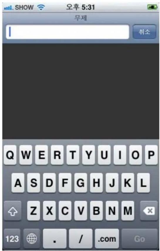

Enter the DVR's address or the Host name with web server port and "/m/" as below. -Enter DVR's user name and password.
Example 1: http://65.60.84.40:8080/m/
Example 2: http://joseph.dyndns.org:8080/m/
-Default login box is too small; you can zoom in with two fingers.


Once you finished inputting username and password, press the Login button.
. Change channel
Touch a channel button.

.Change refresh rate
Touch a refresh button.

logout

Refresh ]
h Rate 500ms Second

Model: DV1630, PAC1558
Chapter 1. General
Access over the Internet 3
Chapter 2. Settings & Connections
Internet Explorer 7
Internet Explorer 6 7
Chapter 3. Basic operations
Automatic disconnection 10
Web viewer screen 10
Log-in 11
Mode control 11
Layout control 12
PTZ controls 12
Quit / Log-out 12
Chapter 4. Search operations
S e a r c h
Playback controls 14
Chapter 1. General
Access over the Internet
Authorized users can access the DVR through the internet anywhere and at anytime.
DVR serves the following three features for web viewer users.
Live view
- Search & Playback (Search permission is required.)
- PTZ camera control (Search or Setup permission is required.)
Remote Site
DVR
(Web Server)
INTERNET
Chapter 2. Settings & Connections
Internet Explorer 7
Step 1. Go to the Tools Menu and select "Internet Options".
Step 2. Move to the "Security" tab.
Step 3. Select "Trusted sites" zone to view section.
Step 4. Add a DVR to Trusted sites.


1) Type DVR IP address/URL directly.
2) Click "Add" button.
3) A new address will be added to here.
4) Uncheck server verification option.
5) Click "Close".
Step 5. Set security level to Low.
* See Step 8. If you want to set the level to "Medium" or "Medium-low".
1) Select "Low" security level for Trusted site.
2) Click "OK"

Step 6. Connect to DVR
1) Enter an address including port number "8080". (Ex. "http://10.0.1.21:8080")
2) Click "Go" or tap Enter key.
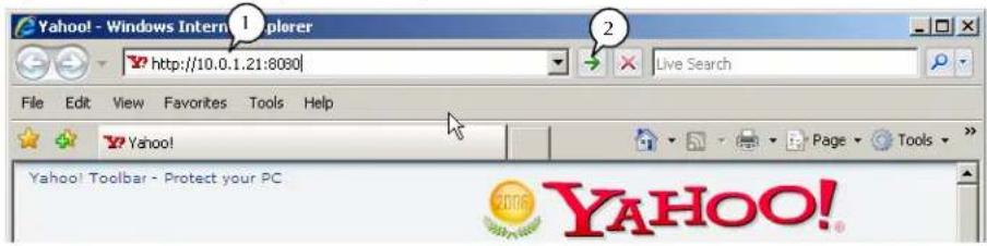
Step 7. Install an ActiveX control
Security warning message will be shown as below.
Select "Install" to access DVR.
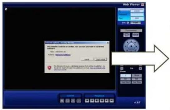
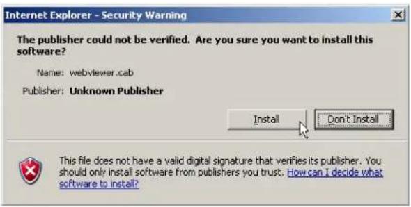
Step 8. For advanced users
If you want to set the security level to "Medium" or "Medium-low" in Step 5., change the following ActiveX options:
1) Automatic prompting for ActiveX controls : Enable
2) Binary and script behaviors : Enable
3) Download unsigned ActiveX controls : Prompt
4) Initialize and script ActiveX controls not marked as safe... : Prompt
Automatic prompting for ActiveX controls
○ Disable
Enable
Binary and script behaviors
○ Administrator approved
○ Disable
Enable
Download unsigned ActiveX controls
○ Disable
Enable
Prompt
Initialize and script ActiveX controls not marked as safe for
○ Disable
Enable
Prompt
Step 1. Go to the Tools Menu and select "Internet Options".
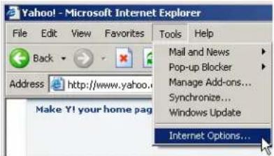
Step 2. Move to the "Security" Tab.

Step 3. Select "Trusted sites" zone to view section.
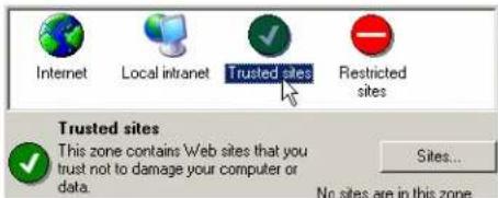
Step 4. Add a DVR to Trusted site.
Click "Sites..." button


Trusted sites windows will be shown.
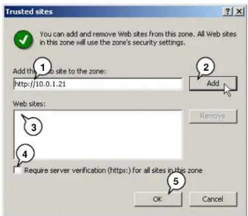
1) Type DVR IP address/URL directly.
2) Click "Add" button.
3) A new address will be added to here.
4) Uncheck server verification option.
5) Click "OK".
Step 5. Set to the default security level.
* See Step 8. If you want to set the level to "Medium" or "Medium-low".
1) Click "Default Level" to set Low Security level for trusted site.
2) Click "OK"

Step 6. Connect to DVR
1) Enter an address including port number "8080". (Ex. "http://10.0.1.21:8080")
2) Click "Go" or tap Enter key.

Step 7. Install an ActiveX control
Security warning message will be shown as below.
Select "Install" to access the DVR.

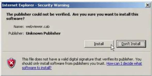
Step 8. For advanced users
If you want to set the security level to "Medium" or "Medium-low" in Step 5., change following ActiveX options, please.
1) Automatic prompting for ActiveX controls : Enable
2) Binary and script behaviors : Enable
3) Download unsigned ActiveX controls : Prompt
4) Initialize and script ActiveX controls not marked as safe... : Prompt
Automatic prompting for ActiveX controls
○ Disable
Enable
Binary and script behaviors
○ Administrator approved
○ Disable
Enable
Download unsigned ActiveX controls
Disable
Enable
Prompt
Initialize and script ActiveX controls not marked as safe for
○ Disable
Enable
Prompt
Chapter 3. Basic operations
Automatic disconnection
DVR denies or disconnects when it is handling a critical task such as following:
- DVR is updating system configurations.
- DVR enters to search mode.
- DVR starts to backup.
Try later when the Web Viewer shows any of these messages.
Web viewer screen
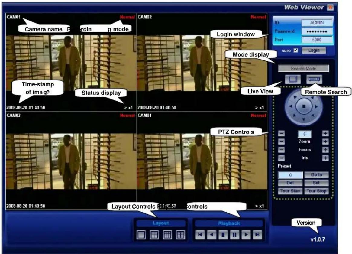
Status Display
"LIVE"
:
Live
Mode
"> x1" to "> x16": Forward playback mode (x1 - x16 means playback speed)
“< x1” to “< x16”: Reverse playback mode (x1 - x16 means playback speed)
Log-in
Step 1. Enter an ID & Password
It must be same ID & Password as the one used to register on the server.
Step 2. Enter a port number (5000)
Do not change this number.
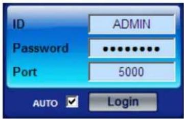
Step 3. Click the Login button to log-in.
You can find that mode display is changed from "Disconnected" to "Live mode".

TIP
Permission
Administrator can assign different permission set-up for each user.
Permission granted to Admin and Guest is fixed to All and LIVE.
Refer to System / User menu on user's manual.
| Permission | Layout Control | Search & Playback | PTZ Controls | Remark |
| Live | O | X | X | |
| Search | O | O | O | |
| Setup | O | O | O | |
| All | O | O | O | Admin |
Guest
Mode control
Web Viewer supports the following two modes:
1) Live Mode
Click Live mode button.
Server will transmit live video streams and audio streams in real time.
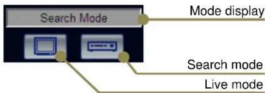
2) Search mode
Click Search mode button.
Calendar search tool and playback controls are supported.
Layout control
You can select a layout between single and split during either mode control.

PTZ controls
You need "Search", "Setup" or "All" permission to use PTZ controls. Must change the layout to 1x1 screen mode prior to using PTZ control

Quit / Log-out
Click the "Quit" icon to log-out.
Mode will be displayed as "Disconnected".

Chapter 4. Search Operations
You can search video data, which is stored on the remote site's DVR, through web viewer.
Search
Step 1. Click Search mode button

Search mode
Step 2. Choose a specific Day & Hour.
Available days are shown in blue high-light on the calendar; choose a specific day.
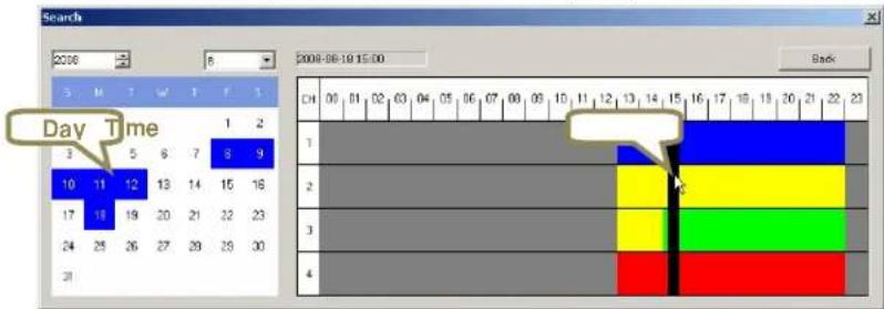

Recording Mode color
Search map is shown with recording mode color described below.
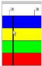
Blue : Recording data by motion event
Yellow : Recording data by alarm in event
Green : Recording data by motion+alarm event
Red : Normal recording data or Panic recording data
Step 4. Choose specific Minute
Playback will be started as soon as you click on a specific minute on the search map.
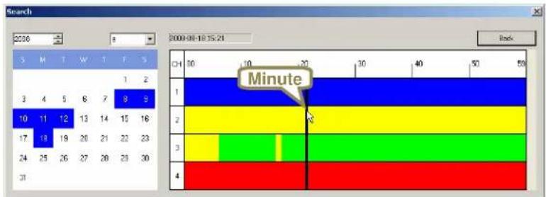
Playback Controls

flowchart
graph LR
    A["Previous frame"] --> B["Playback"]
    C["Reverse playback"] --> B
    D["Stop"] --> B
    E["Next frame"] --> B
    F["Forward playback"] --> B
    G["Pause"] --> B

TIP Fast playback control
Web Viewer supports multiple playback speeds (x1, x2, x4, x8 and x16).
The speed is changed when the playback button is clicked during playback.

- Chapter 1. Installation
- Chapter 2. Operation
- System Requirements
- Installation
- Step 1. Execute setup program
- Step 2. License Agreement
- Step 3. Select language
- Step 4. Choose Destination & Start to install
- Step 5. Finish
- Run BackupViewer
- st Option: BackupViewer icon on your desktop
- nd Option: BackupViewer on Start menu
- Open a backup file
- st Option: using the “Open” icon
- 2nd Option: Using the menu panel
- Playback control buttons
- Playback position display and control
- Screen layout control
- Screen capture
- AVI backup
- Digital Video Recorder
- CMS (Central Monitoring Software)
- Chapter 1 Installation
- Chapter 2 Operation
- Step 3. Click the "Install" button.
- Step 4. Click "Close" when Installation is complete.
- Run CMS software
- st Option: CMS icon on desktop
- 2nd Option: CMS software on Start menu
- CMS software login
- CMS Main screen
- Register DVR
- st Option: Auto Registration
- nd Option: Manual registration
- Connect/Disconnect DVR
- Connect
- Disconnect
- Live
- Camera view
- Stop searching at 1 channel search
- DVR view
- View Layout
- Search
- Search Mode
- E-Map
- Add Map
- Camera view & Alarm In/Out control
- Map Save
- Map load
- PTZ
- Alarm In/Out
- Event
- Event show
- Event hide
- Event delete
- Event Search
- Event Save
- Backup
- DVR Setup
- DVR Upgrade
- CMS Options & Version
- Administrator Password
- BMP Capture
- AVI file Capture
- Chapter 2 Pre-Acknowledgement
- Chapter 3 Operation
- Chapter 4 Setup
- Chapter 5 Service Menu
- Chapter 1 - Installation
- Box Contents
- Choosing a location for installation
- ✿ Rear panel layout
- ✿ Basic connections
- Connect Cameras
- Connect to network
- ◆ Connect a mouse (optional)
- Connect power
- Step 1. Set GMT/Location
- Step 2. Initial time synchronization in Admin menu (Optional)
- Step 3. Time adjustment
- Step 4. Periodical time synchronization(Optional)
- Chapter 2. Pre-acknowledgement
- Front Panel
- Multiple unit with single remote controller
- Mouse operations
- Virtual keyboard
- Login
- Entering User menu
- ID
- Password
- Permission
- Hidden
- DST vs. Location
- Effects of daylight
- Updating DST rule
- Shutdown (Auto power off)
- Step 1. Shutdown in menu
- Step 2. Auto power off
- Chapter 3. Operation
- View panel
- Camera pane
- Status bar
- Auto-hiding of status bar & Playback control bar
- Panic mode (emergency recording)
- ◆ Single-screen display
- Selecting channels over 10
- ◆ Multi screen display
- ◆ Audio volume control
- Using Volume button
- Using Quick Menu
- PTZ (Pan / Tilt / Zoom) (Single screen mode only)
- Entering into PTZ mode
- PTZ control panels
- Pan & Tilt
- Preset
- Set a new preset point
- View a preset point
- Delete a preset point
- Search & Playback
- ◆ Playback Control
- Remote Controller
- GUI
- ◆ Quick play
- ◆ Sequence & screen separate
- OSD On/Off
- ◆ De-interlace On/Off
- ◆ Entering to search menu
- Front panel & Remote controller
- GUI (Mouse)
- ◆ Calendar Search
- Step 1. Choosing a date
- Step 2. Choosing an hour
- Step 3. Choosing a minute & Play
- Step 4. Playback Control & Return to search menu
- Daylight in calendar search mode
- Daylight in event search mode
- ◆ Backup device
- ◆ Backup file type
- ❖ Entering Backup Menu
- Daylight in backup
- Chapter 4. Setup
- Summary
- ◆ Record - Setup
- Size
- fps (recording frame rate)
- D1 real time recording
- Quality
- ◆ Record - Network
- Fps (network transmission frame rate)
- ◆ Record - Schedule
- Recording Mode
- Scheduling
- ◆ Record :: Holiday
- Add a new holiday
- Delete a holiday
- Delete all holiday
- ◆ Camera - Setup
- Name
- Enable
- Audio
- Sat / Con / Bri
- ◆ Camera - Motion
- Region
- Sensitivity
- Camera - PTZ
- Model
- Settings
- Event - Alarm In
- Type
- Link Camera
- Event - Alarm Out
- Alarm Out Number?
- Duration
- Motion
- Video Loss
- Alarm In
- Event - Email
- Power Up
- HDD
- Event - Beep
- ◆ Display - Settings
- Camera name
- Record mode
- Audio record icon
- Status bar auto-hide
- Sequence
- Alpha blending
- ◆ Display - Spot
- Mode
- Channel
- ◆ Storage - Storage
- Temperature Limit
- Refresh
- Device / Capacity
- Format
- Temperature
- ◆ Storage - S.M.A.R.T.
- Device
- Attribute
- Value
- Worst
- Threshold
- ◆ Storage - Record
- Record Duration
- Write Mode
- Early Warning
- ◆ Storage - Backup
- System Settings
- ◆ System - Network
- DHCP
- ◆ System - DDNS
- DDNS
- MY-DDNS.COM
- DYNDNS
- Add New Hostname
- ◆ System - Server
- TCP / UDP / HTTP port
- Max. Connect
- Max. Search
- Event Server
- ◆ System - Log
- Start / End
- Save
- System - User
- System - Info
- Remocon ID
- Firmware Version
- Kernel Version
- MAC address
- Service Menu/ Admin Menu.
- System - Email
- SMTP Auth
- Server
- Passowrd
- TestSend
- ◆ System - Time Sync.
- NTP Server
- Port (UDP)
- Period (Hour)
- Server Time
- Get
- Apply
- Failure of time synchronization
- System - Etc
- Key Beep
- Temperature Unit
- Auto-Logout
- VideoMode
- VideoLoss Record
- Chapter 5. Admin Menu
- Entering the Service Menu
- Admin - Upgrade
- Admin - Config
- Admin - Format
- Admin – DateTime
- Time Sync.
- Current Time
- GMT/Location
- Admin - Etc
- Language
- Delete Log
- Mac
- Appendix 1. Menu tree
- [Continued]
- Appendix 2. Factory default settings
- Appendix 3. Limited 1 Year Warranty
- Appendix 4. How to obtain Factory Service
- Manual of Mobile Viewer
- Safari for iPhone
- Change channel
- .Change refresh rate
- logout
- Chapter 1. General
- Chapter 2. Settings & Connections
- Chapter 3. Basic operations
- Chapter 4. Search operations
- Access over the Internet
- Internet Explorer 7
- Step 4. Add a DVR to Trusted sites.
- Step 5. Set security level to Low.
- Step 6. Connect to DVR
- Step 7. Install an ActiveX control
- Step 8. For advanced users
- Step 4. Add a DVR to Trusted site.
- Step 5. Set to the default security level.
- Automatic disconnection
- Web viewer screen
- Status Display
- Log-in
- TIP
- Mode control
- Layout control
- PTZ controls
- Quit / Log-out
- Recording Mode color
- Playback Controls
- TIP Fast playback control
Brand : Clover Electronics
Model : DV1630
Category : Voice recorder