
MC-602 - Audio Receiver MCINTOSH - Free user manual and instructions
Find the device manual for free MC-602 MCINTOSH in PDF.


| Product Type | Stereo Integrated Amplifier / Receiver |
| Brand | McIntosh |
| Model | MC-602 |
| Dimensions (W x H x D) | 17.5 in x 5.4 in x 14.5 in (44.5 cm x 13.7 cm x 36.8 cm) |
| Weight | 28.5 lb (12.9 kg) |
| Power Output | 130 Watts per channel into 8 ohms |
| Frequency Response | 20 Hz - 20 kHz ±0.25 dB |
| Total Harmonic Distortion (THD) | ≤0.025% at rated power |
| Input Sensitivity | 1.2 V (high level), 2.5 mV (phono MM) |
| Signal-to-Noise Ratio (A-weighted) | 100 dB (line), 80 dB (phono) |
| Speaker Impedance | 4 ohms minimum |
| Inputs | Phono (MM), 4x Line, 1x Tape Monitor, 1x Preamp Out / Main In |
| Outputs | Speaker A/B switchable, Headphone jack, Tape Rec Out |
| Power Consumption | 450 W maximum |
| Power Supply | AC 120V 60 Hz (US version) |
| Controls | Volume, Balance, Bass, Treble, Input Selector, Tape Monitor, Loudness, Power |
| Construction | Brushed aluminum faceplate, black chassis |
| Cooling | Ventilation slots; avoid blocking |
| Cleaning | Use a soft dry cloth; do not use solvents |
| Safety Features | Thermal protection, speaker short-circuit protection |
| Included Accessories | Power cord, user manual |
Frequently Asked Questions - MC-602 MCINTOSH
User questions about MC-602 MCINTOSH
0 question about this device. Answer the ones you know or ask your own.
Ask a new question about this device
Download the instructions for your Audio Receiver in PDF format for free! Find your manual MC-602 - MCINTOSH and take your electronic device back in hand. On this page are published all the documents necessary for the use of your device. MC-602 by MCINTOSH.
USER MANUAL MC-602 MCINTOSH
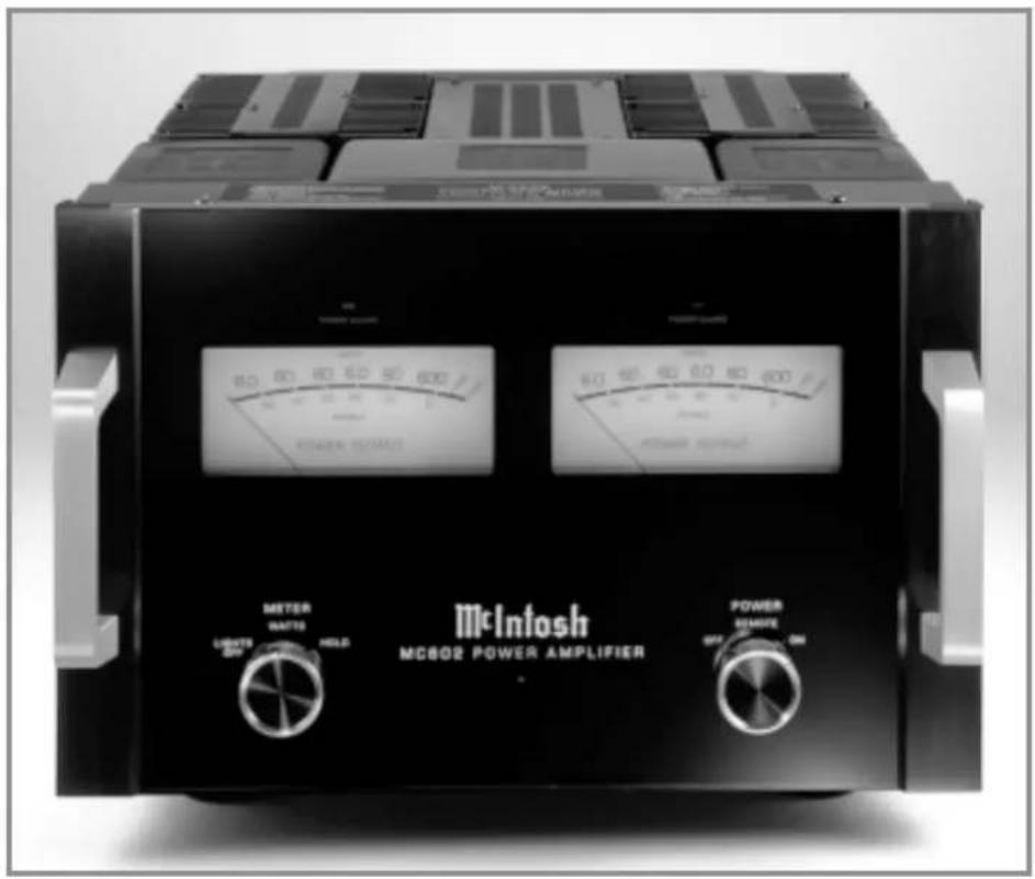
MC602 Power Amplifier
MC602
The lightning flash with arrowhead, within an equilateral triangle, is intended to alert the user to the presence of uninsulated “dangerous voltage” within the product’s enclosure that may be of sufficient magnitude to constitute a risk of electric shock to persons.

AVIS RISQUE DE CHOC ELECTRIQUE - NE PAS OUVRIR.
The exclamation point within an equilateral triangle is intended to alert the user to the presence of important operating and maintenance (servicing) instructions in the literature accompanying the appliance.
WARNING - TO REDUCE RISK OF FIRE OR ELECTRICAL SHOCK, DO NOT EXPOSE THIS EQUIPMENT TO RAIN OR MOISTURE.
NO USER-SERVICEABLE PARTS INSIDE. REFER SERVICING TO QUALIFIED PERSONNEL.
To prevent the risk of electric shock, do not remove cover or back. No user serviceable parts inside.
IMPORTANT SAFETY INSTRUCTIONS!
PLEASE READ THEM BEFORE OPERATING THIS EQUIPMENT.
General:
- Read these instructions.
- Keep these instructions.
- Heed all warnings.
- Follow all instructions.
-
Warning: To reduce risk of fire or electrical shock, do not expose this equipment to rain or moisture. This unit is capable of producing high sound pressure levels. Continued exposure to high sound pressure levels can cause permanent hearing impairment or loss. User caution is advised and ear protection is recommended when playing at high volumes.
-
Caution: to prevent electrical shock do not use this (polarized) plug with an extension cord, receptacle or other outlet unless the blades can be fully inserted to prevent blade exposure.
-
Unplug this equipment during lightning storms or when unused for long periods of time.
-
Only use attachments/accessories specified by the manufacturer.
Installation:
- The equipment shall be installed near the AC Socket Outlet and the disconnect device shall be easily accessible.
- Do not block any ventilation openings. Install in accordance with the manufacturer's instructions.
- Do not install near any heat sources such as radiators, heat registers, stoves, or other equipment (including amplifiers) that produce heat.
- Do not use this equipment near water.
- Do not expose this equipment to dripping or splashing and ensure that no objects filled with liquids, such as vases, are placed on the equipment.
- Use only with the cart, stand, tripod, bracket, or table specified by the manufacturer, or sold with the equipment.
When a cart is used, use caution when moving the cart/equipment combination to avoid injury from tip-over.

Connection:
- Connect this equipment only to the type of AC power source as marked on the unit.
- Protect the power cord from being walked on or pinched particularly at plugs, convenience receptacles, and the point where they exit from the equipment.
- Do not defeat the safety purpose of the polarized or grounding-type plug.
A polarized plug has two blades with one wider than the other. A grounding type plug has two blades and a third grounding prong. The wide blade or the third prong are provided for your safety. If the provided plug does not fit into your outlet, consult an electrician for replacement of the obsolete outlet.
- Do not overload wall outlets, extension cords or integral convenience receptacles as this can result in a risk of fire or electric shock.
- To completely disconnect this equipment from the AC Mains, disconnect the power supply cord plug from the AC receptacle.
Care of Equipment:
- Clean only with a dry cloth.
- Do not permit objects or liquids of any kind to be pushed, spilled and/or fall into the equipment through enclosure openings.
- Unplug the power cord from the AC power outlet when left unused for a long period of time.
Repair of Equipment:
- Refer all servicing to qualified service personnel. Servicing is required when the equipment has been damaged in any way, such as power-supply cord or plug is damaged, liquid has been spilled or objects have fallen into the equipment, the equipment has been exposed to rain or moisture, does not operate normally, or has been dropped.
- Do not attempt to service beyond that described in the operating instructions. All other service should be referred to qualified service personnel.
- When replacement parts are required, be sure the service technician has used replacement parts specified by McIntosh or have the same characteristics as the original part. Unauthorized substitutions may result in fire, electric shock, or other hazards.
- Upon completion of any service or repairs to this product, ask the service technician to perform safety checks to determine that the product is in proper operating condition.
Thank You
Your decision to own this McIntosh MC602 Power Amplifier ranks you at the very top among discriminating music listeners. You now have “The Best.” The McIntosh dedication to “Quality,” is assurance that you will receive many years of musical enjoyment from this unit.
Please take a short time to read the information in this manual. We want you to be as familiar as possible with all the features and functions of your new McIntosh.
Please Take A Moment
The serial number, purchase date and McIntosh dealer name are important to you for possible insurance claim or future service. The spaces below have been provided for you to record that information:
Serial Number: ____
Purchase Date: ____
Dealer Name: ____
Technical Assistance
If at any time you have questions about your McIntosh product, contact your McIntosh dealer who is familiar with your McIntosh equipment and any other brands that may be part of your system. If you or your dealer wish additional help concerning a suspected problem, you can receive technical assistance for all McIntosh products at:
McIntosh Laboratory, Inc.
2 Chambers Street
Binghamton, New York 13903
Phone: 607-723-1545
Fax: 607-723-3636
Customer Service
If it is determined that your McIntosh product is in need of repair, you can return it to your dealer. You can also return it to the McIntosh Laboratory Service Department. For assistance on factory repair return procedure, contact the McIntosh Service Department at:
McIntosh Laboratory, Inc.
2 Chambers Street
Binghamton, New York 13903
Phone: 607-723-3515
Fax: 607-723-1917
Copyright 2000 © by McIntosh Laboratory, Inc.
Table of Contents
Safety Instructions 2
Thank You and Please Take a Moment.... 3
Technical Assistance and Customer Service .... 3
Table of Contents and General Notes 4
Introduction 4
Performance Features 4
Dimensions 5
Installation 6
Rear Panel Connections and Switch 7
How to Connect 8
Front Panel Displays and Controls 10
How to Operate .... 11
Technical Description 12
Notes 16
Specifications 18
Packing Instruction 19
General Notes
Caution: The MC602 Amplifier weight is 155 pounds (70.31 kilograms). It requires two or more persons to safely handle when moving the amplifier.
- The following Connecting Cable is available from the McIntosh Parts Department:
Power Control Cable Part No. 170-202
Six foot, 2 conductor shielded, with two 1/8 inch stereo mini phone plugs.
-
For additional connection information, refer to the owner's manual(s) for any component(s) connected to the MC602.
-
The MC602 mutes the speaker outputs for approximately two seconds when first turned on.
-
It is very important that loudspeaker cables of adequate size be used, so that there will be no power loss. The size is specified in Gauge Numbers or AWG, (American Wire Gauge). The smaller the Gauge number, the larger the wire size:
If your loudspeaker cables are 50 feet (38.1m) or less, use at least 14 Gauge. If your loudspeaker cables are 100 feet (76.2m) or less use at least 12 Gauge.
- Pin configuration for the XLR Balanced Input connectors on the MC602: PIN 1: Shield or ground
PIN 2: + input
PIN 3: - input
-
In the event that the MC602 over heats, due to improper ventilation and/or high ambient temperature, the protection circuits will activate. The Front Panel Power Guard LEDs will continuously indicate ON and the audio will be muted. When the MC602 has returned to a safe operating temperature, normal operation will resume.
-
The MC602 incorporates the very latest in Fully Double Balanced Circuitry. As a result, the Loudspeaker Negative Connections are above chassis ground and are not common between channels. Do not combine any connections together or ground them.
Introduction
Now you can take advantage of traditional McIntosh standards of excellence in the MC602 Power Amplifier. Two 600 watt high current output channels will drive any high quality loudspeaker system to its ultimate performance.
The MC602 reproduction is sonically transparent and absolutely accurate. The McIntosh Sound is “The Sound of the Music Itself.”
Performance Features
●Power Output
The MC602 consists of two separate power amplifier channels, each capable of 600 watts into 2, 4 or 8 ohm speakers with less than 0.005% distortion.
●Full Balanced Circuity
The MC602 is fully balanced from inputs to outputs. Each channel consists of two matched power amplifiers operating in push-pull with their outputs combined in a McIntosh Autoformer. The double balanced configuration cancels virtually all distortion.
●Power Guard
Both channels include the patented McIntosh Power Guard circuit that prevents the amplifier from being overdriven into clipping, with its harsh distorted sound that can also damage your valuable loudspeakers.
●Sentry Monitor and Thermal Protection
McIntosh Sentry Monitor power output stage protection circuits ensure the MC602 will have a long and trouble free operating life. Built-in Thermal Protection Circuits guard against overheating.
●Patented Autoformers
McIntosh designed and manufactured Output Autoformers provide an ideal match between the amplifier output stages and speaker loads of 2, 4 and 8 ohms. The Autoformers also provide perfect DC protection for your valuable loudspeakers.
●Illuminated Power Meters
The Illuminated Power Output Watt Meters on the MC602 are peak responding, and indicate the true power output of the amplifier. The Peak Watt Hold Mode allows the meters to temporarily stay at the highest power output and then slowly decay.
The following dimensions can assist in determining the best location for your MC602. There is additional information on the next page pertaining to installing the MC602 into cabinets.
Front View of the MC602

Rear View of the MC602
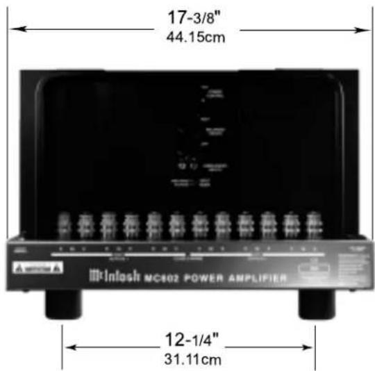
Side View of the MC602

Installation
Caution: The MC602 Amplifier weight is 155 pounds (70.31 kilograms). It requires two or more persons to safely handle when moving the amplifier. The MC602 can be placed upright on a table or shelf, standing on its four feet. The four feet may be removed from the bottom of the MC602 when it is custom installed as outlined below. The four feet together with the mounting screws should be retained for possible future use if the MC602 is removed from the custom installation and used free standing. It also can be custom installed in a piece of furniture or cabinet of your choice. The required panel cutout, ventilation cut-out and unit dimensions are shown.
Always provide adequate ventilation for your MC602. Cool operation ensures the longest possible operating life for any electronic instrument. Do not install the MC602 directly above a heat generating component such as a high powered amplifier. If all the components are installed in a single cabinet, a quiet running ventilation fan can be a definite asset in maintaining all the system components at the coolest possible operating temperature.
A custom cabinet installation should provide the following minimum spacing dimensions for cool operation. Allow at least 6 inches (15.24 cm) above the top, 2 inches (3.81cm) below the bottom and 1 inch (2.54 cm) on each side of the amplifier, so that airflow is not obstructed. Allow 22 inches (55.88 cm) depth behind the front panel.
Allow 2 inches (5.08 cm) in front of the mounting panel for handle clearance. Be sure to cut out a ventilation hole in the mounting shelf according to the dimensions in the drawing.
MC602 Front Panel
Custom Cabinet Cutout

MC602 Side View in Custom Cabinet
MC602 Bottom View in Custom Cabinet

Caution: The Loudspeaker ⊙ Negative Connections are above chassis ground and are not common between channels. Do not combine any connections together or ground them.
How to Connect the MC602
Caution: The supplied AC Power Cord should not be connected to the Rear Panel of the MC602 Amplifier until after the Loudspeaker Connections have been made and the supplied protective Terminal Connections Cover has been installed. Failure to observe this could result in Electric Shock.
- For Remote Power Control, connect a power control cable from the Control Center or Preamplifier Power Control Out to the MC602 Power Control In.
- Connect cables from the Balanced Outputs of a McIntosh Preamplifier or Control Center to the MC602 Balanced Inputs.
Note: An optional hookup is to use unbalanced cables.
- Prepare the Loudspeaker Hookup Cables that attach to the MC602 Power Amplifier by choosing one of the methods below:
Bare wire cable ends:
Carefully remove sufficient insulation from the cable
ends, refer to figures 1, 2 & 3. If the cable is stranded, carefully twice the strands together as tightly as possible.


Note: If desired, the twisted ends can be tinned with solder to keep the strands together, or attach spade lug and/or banana connector.
Spade lug or prepared wire connection:
Insert the spade lug connector or prepared section of the cable end into the terminal side access hole, and tighten the terminal cap until the cable is firmly clamped into the terminal so the wires cannot slip out. Refer to figures 4, 5 & 6.
Banana plug connection:
Insert the banana plug into the hole at the top of the terminal. Tighten the top portion of the terminal post and the set screw to secure the banana plug in place.
Note: The use of Banana Plugs is for use in the United States and Canada only.
- Connect the loudspeaker hookup cables to the output terminals that match the impedance of your loudspeakers, being careful to observe the correct polarities. Output impedance connections of 2 ohms, 4 ohms and 8 ohms are provided. If the impedance of your loudspeakers is in-between the available connections, use the nearest lower impedance connection.
WARNING: Loudspeaker terminals are hazardous live and present a risk of electric shock. For additional instruction on making Loudspeaker Connections contact your McIntosh Dealer or McIntosh Technical Support.
- Attach the supplied Terminal Connections Cover with the four Philip Head Mounting Screws (10-32 x 1/2 inch) to the Rear Panel of the MC602 Amplifier. Refer to figure 7.
Note: There are six openings on the bottom edge of the cover to allow for the Loudspeaker's Cable to exit the MC602. The Rear Chassis Handle ("U" shaped) has tapped screw openings on both sides for securing the cover to the MC602.
- Connect the MC602 power cord to an active AC outlet.

Figure 7
McIntosh C200C Controller McIntosh C200P Preamplifier

Caution: The Loudspeaker ⊖ Negative Connections are above chassis ground and are not common between channels. Do not combine any connections together or ground them.

How to Operate the MC602
Power On
To have the MC602 automatically turn On or Off when a control center turns on or off, rotate the power switch to the remote position. For manual operation, rotate the power
switch to the On or Off position as desired. Refer to figure 8.
Note: There must be a power control connection between the MC602 and the McIntosh Control Center, in order for the remote power turn-on to function.
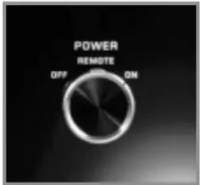
Figure 8
Meter Selection
Rotate the meter mode switch to select the meter operation mode you desire. Refer to figures 9 and 10.
Lights Off - Meter lights are
turned off and the meters will con- tinue to indicate the power output.
Watts- The meters respond to all the musical information being produced by the amplifier. They indicate to an accurate power output with 2000Hz tone burs

Figure 9
Hold - The meter pointer is locked to the highest power peak in a sequence of peaks. It is electronically held to this power level until a
higher power peak passes through the ampli- fier. The

Figure 10
meter pointer will then rise to the newer higher indication. If no further power peaks are reached, the meter pointer will very slowly return to its rest position or lower power level. The decay rate is approximately 6dB per minute.
Note: The MC602 Power Output Meters indicate the actual wattage delivered to the loudspeakers by responding to the combination of current and voltage output.
Input Mode Switch
The Input Mode Switch, which is located on the Rear
Panel of the MC602, allows you to select either the Balanced or Unbalanced Inputs. Refer to figure 11.

Figure 11
McIntosh
Technical Description
McIntosh Laboratory, the company who introduced the world's first amplifier that could be called "High Fidelity", has done it again. The McIntosh engineering staff has created a power amplifier without compromise, using the most advanced McIntosh circuit design concepts.
A continuous average power output rating of 600 watts and with an output current of greater than 150 amperes per channel, makes this not only the most advanced, but also the most powerful amplifier McIntosh has ever manufactured. The distortion limits for the MC602 are no more than 0.005% at rated power output for all frequencies from 20Hz to 20,000Hz. Typical performance at mid frequencies is less than 0.002%. The true distortion readings on the MC602 are so low, it takes special measuring techniques to make accurate readings. The MC602 can deliver the best possible performance from any type of high quality loudspeaker system.
Creating an amplifier with this level of performance did

natural_image
Interior view of an electronic device showing internal circuit board, wiring, and modules (no visible text or symbols)Inside of the MC602
not come easily. Many months of design, testing and measuring were required. Extensive controlled listening tests, the ultimate form of measuring, were made before the final design was accepted.
Design Philosophy
The design philosophy incorporated in the MC602 involved several different techniques, all based on sound scientific logic. Every stage of voltage or current amplification must be as linear as possible prior to the use of negative feedback. McIntosh engineers know how to properly design negative feedback circuits so they contribute to the extremely low distortion performance expected from a McIntosh amplifier. The typical McIntosh owner would never accept the approximately 100 times higher distortion of many non-feedback designs.
Double Balanced Push-Pull design is used from input to output. Each half of the amplifier contains complimentary

flowchart
graph TD
    subgraph BlockDiagram
        direction TB
        A["Input"] --> B["PG REDUCTOR"]
        B --> C["PG POWER"]
        C --> D["POWER CHAND"]
        D --> E["DCY AMP"]
        E --> F["UBSOFT VOLTAGE AMP"]
        F --> G["+ PREDUCE"]
        G --> H["+ OUTR"]
        H --> I["CURRENT TRANSICUM"]
        I --> J["CLINEXT LOS AMP"]
        J --> K["VOLTAGE LOS AMP"]
        K --> L["METER SWITCH"]
        L --> M["OUTPUT ALTO POWER"]
        N["LEFT ALTO INPUT"] --> O["ATTENUATOR"]
        O --> P["INCEROVER"]
        P --> Q["TURD ON DELA"]
        Q --> R["PB ATTENUATOR"]
        S["TURD ON DELA"] --> T["UPP RELIANCE INPUT"]
        U["TURD ON DELA"] --> V["UPP RELIANCE OUTPUT"]
        W["TURD ON DELA"] --> X["TURD ON DELA"]
        Y["TURD ON DELA"] --> Z["TURD ON DELA"]
    end

    subgraph BlockDiagram
        direction TB
        A --> C
        C --> D
        D --> E
        E --> F
        F --> G
        G --> H
        H --> I
        I --> J
        J --> K
        K --> L
        L --> M
        M --> N
        N --> O
        O --> P
        P --> Q
        Q --> R
        R --> S
        S --> T
        T --> U
        U --> V
        V --> W
        W --> X
        X --> Y
        Y --> Z
        Z --> R
    end

    subgraph BlockDiagram
        direction TB
        A --> D
        D --> E
        E --> F
        F --> G
        G --> H
        H --> I
        I --> J
        J --> K
        K --> L
        L --> M
        M --> N
        N --> O
        O --> P
        P --> Q
        Q --> R
        R --> S
        S --> T
        T --> U
        U --> V
        V --> W
        V --> X
        X --> Y
        Y --> Z
    end

    subgraph BlockDiagram
        direction TB
        A --> F
        F --> G
        G --> H
        H --> I
        I --> J
        J --> K
        K --> L
        L --> M
        M --> N
        N --> O
        O --> P
        P --> Q
        Q --> R
    end

    subgraph BlockDiagram
        direction TB
        A --> H
        H --> I
        I --> J
        J --> K
        K --> L
        L --> M
        M --> N
        N --> O
        O --> P

    end

    style BlockDiagram fill:#f9f,stroke:#333,stroke-width:2px

    note1["RIGHT REDUCTOR INPUT"]:: "LEFT ALTO INPUT"
    note2["ATTENUATOR"]:: "INTENUATOR"
    note3["INCEROVER"]:: "INCEROVER"
    note4["TURD ON DELA"]:: "TURD ON DELA"
    note5["TURD ON DELA"]:: "TURD ON DELA"
    note6["TURD ON DELA"]:: "TURD ON DELA"
    note7["TURD ON DELA"]:: "TURD ON DELA"
    note8["TURD ON DELA"]:: "TURD ON DELA"
    note9["TURD ON DELA"]:: "TURD ON DELA"
    note10["TURD ON DELA"]:: "TURD ON DELA"
    note11["TURD ON DELA"]:: "TURD ON DELA"
    note12["TURD ON DELA"]:: "TURD ON DELA"
    note13["TURD ON DELA"]:: "TURD ON DELA"
    note14["TURD ON DELA"]:: "TURD ON DELA"
    note15["TURD ON DELA"]:: "TURD ON DELA"
    note16["TURD ON DELA"]:: "TURD ON DELA"
    note17["TURD ON DELA"]:: "TURD ON DELA"
    note18["TURD ON DELA"]:: "TURD ON DELA"
    note19["TURD ON DELA"]:: "TURD ON DELA"
    note20["TURD ON DELA"]:: "TURD ON DELA"
    note21["TURD ON DELA"]:: "TURD ON DELA"
    note22["TURD ON DELA"]:: "TURD ON DELA"
    note23["TURD ON DELA"]:: "TURD ON DELA"
    note24["TURD ON DELA"]:: "TURD ON DELA"
    note25["TURD ON DELA"]:: "TURD ON DELA"
    note26["TURD ON DELA"]:: "TURD ON DELA"
    note27["TURD ON DELA"]:: "TURD ON DELA"
    note28["TURD ON DELA"]:: "TURD ON DELA"
    note29["TURD ON DELA"]:: "TURD ON DELA"
    note30["TURD ON DELA"]:: "TURD ON DELA"
    note31["TURD ON DELA"]:: "TURD ON DELA"
    note32["TURD ON DELA"]:: "TURD ON DELA"
    note33["TURD ON DELA"]:: "TURD ON DELA"
    note34["TURD ON DELA"]:: "TURD ON DELA"
    note35["TURD ON DELA"]:: "TURD ON DELA"
    note36["TURD ON DELA"]:: "TURD ON DELA"
    note37["TURD ON DELA"]:: "TURD ON DELA"
    note38["TURD ON DELA"]:: "TURD ON DELA"
    note39["TURD ON DELA"]:: "TURD ON DELA"
    note40["TURD ON DELA"]:: "TURD ON DELA"
    note41["TURD ON DELA"]:: "TURD ON DELA"
    note42["TURD ON DELA"]:: "TURD ON DELA"
    note43["TURD ON DELA"]:: "TURD ON DELA"
    note44["TURD ON DELA"]:: "TURD ON DELA"
    note45["TURD ON DELA"]:: "TURD ON DELA"
    note46["TURD ON DELA"]:: "TURD ON DELA"
    note47["TURD ON DELA"]:: "TURD ON DELA"
    note48["TURD ON DELA"]:: "TURD ON DELA"
    note49["TURD ON DELA"]:: "TURD ON DELA"
    note50["TURD ON DELA"]:: "TURD ON DELA"
    note51["TURD ON DELA"]:: "TURD ON DELA"
    note52["TURD ON DELA"]:: "TURD ON DELA"
    note53["TURD ON DELA"]:: "TURD ON DELA"
    note54["TURD ON DELA"]:: "TURD ON DELA"
    note55["TURD ON DELA"]:: "TURD ON DELA"
    note56["TURD ON DELA"]:: "TURD ON DELA"
    note57["TURD ON DELA"]:: "TURD ON DELA"
    note58["TURD ON DELA"]:: "TURD ON DELA"
    note59["TURD ON DELA"]:: "TURD ON DELA"
    note60["TURD ON DELA"]:: "TURD ON DELA"
    note61["TURD ON DELA"]:: "TURD ON DELA"
    note62["TURD ON DELA"]:: "TURD ON DELA"
    note63["TURD ON DELA"]:: "TURD ON DELA"
    note64["TURD ON DELA"]:: "TURD ON DELA"
    note65["TURD ON DELA"]:: "TURD ON DELA"
    note66["TURD ON DELA"]:: "TURD ON DELA"
    note67["TURD ON DELA"]:: "TURD ON DELA"
    note68["TURD ON DELA"]:: "TURD ON DELA"
    note69["TURD ON DELA"]:: "TURD ON DELA"
    note70["TURD ON DELA"]:: "TURD ON DELA"
    note71["TURD ON DELA"]:: "TURD ON DELA"
    note72["TURD ON DELA"]:: "TURD ON DELA"
    note73["TURD ON DELA"]:: "TURD ON DELA"
    note74["TURD ON DELA"]:: "TURD ON DELA"
    note75["TURD ON DELA"]:: "TURD ON DELA"
    note76["TURD ON DELA"]:: "TURD ON DELA"
    note77["TURD ON DELA"]:: "TURD ON DELA"
    note78["TURD ON DELA"]:: "TURD ON DELA"
    note79["TURD ON DELA"]:: "TURD ON DELA"
    note80["TURD ON DELA"]:: "TURD ON DELA"
    note81["TURD ON ELAW"]
    note82["ENCOUNTER SWITCHED"]
    note83["RUTE"]
    note84["ATTENUATOR"]
    note85["INCEROVER"]

    %% Legend at the bottom of the Block Diagram
Figure 12
McIntosh
balanced circuitry. The resulting double balanced configuration cancels even order distortion. Refer to figure 12 on page 13.
All transistors are selected to have nearly constant current gain over the entire current range they must cover. Output transistors in particular, have matched uniform current gain, high current bandwidth product and large active region safe operating area. An automatic tracking bias system completely eliminates any trace of crossover distortion. Precision metal film resistors and low dielectric absorption film capacitors are used in all critical circuit locations.
The output signals of the two balanced circuits are coupled together in the unique McIntosh MC602 Output Autoformer. It provides low distortion power transfer at frequencies from below 20Hz to well beyond 20,000Hz with optimum impedance points of two ohms, four ohms and eight ohms. The unequaled expertise of McIntosh in the design and manufacturing of autoformers is legendary in the high fidelity industry.
The high efficiency circuit design of the MC602 contributes to low operating temperatures. More than 290 square inches of heat sink area keep the MC602 operating safely with convection cooling. No fans are needed.
Autoformers
All solid state power amplifier output circuits work best into what is called an optimum load. This optimum load may vary considerably from what a loudspeaker requires. In the case of more than one loudspeaker connected in parallel, the load to the power amplifier may drop to two ohms or even less. A power amplifier connected to a load that is lower than optimum, causes more output current to flow, which results in extra heat being generated in the power output stage. This increase in temperature will result in a reduced life expectancy for the amplifier.
The Autoformer creates an ideal match between the power amplifier output stage and the loudspeaker. A McIntosh amplifier with an Autoformer can be used to safely drive multiple speakers without reducing the life expectancy of the power amplifier. Refer to figure 13.
There is absolutely no performance limitation with an Autoformer. Its frequency re-

natural_image
Mechanical component with coiled cable and cylindrical housing (no visible text or symbols)Figure 13
sponse exceeds that of the output circuit itself, and extends well beyond the audible range. Its distortion level is so low it is virtually impossible to measure.
In the rare event of a power amplifier output circuit failure, the McIntosh Autoformer provides absolute protection from possible damage to your valuable loudspeakers. The unequaled expertise of McIntosh in the design and manufacturing of Autoformers is legendary in the high fidelity industry. McIntosh engineers know how to do it right.
Protection Circuits
The MC602 incorporates it's version of the McIntosh Sentry Monitor output transistor protection circuit. Refer to Figure 14. There is absolutely no compromise in sonic performance with this circuit, and it ensures safe operation of the amplifier under even the most extreme operating condi-
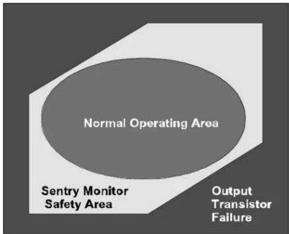
Figure 14
tions. The different types of protection circuits incorporated in the MC602 insure a long and safe operating life. This is just one of the many characteristics of McIntosh Power Amplifiers that make them world famous.
The MC602 also includes the unique patented McIntosh Power Guard circuit.
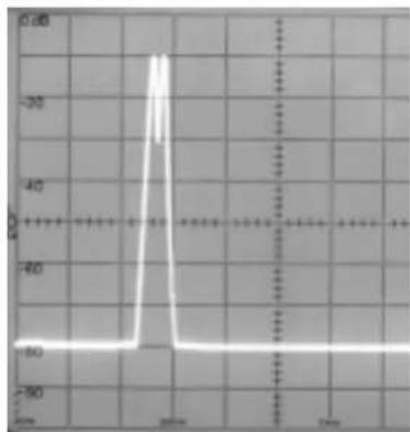
Power Guard eliminates the possibility of ever overdriving the amplifier into clipping. Refer to figures 15, 16 and 17. An overdriven amplifier can produce both audible and inaudible distortion levels exceeding 40%. The audible distortion is unpleasant to hear, but the inaudible ultrasonic distortion is also undesir-
Input Test Signal
line
| Time | Value | |------|-------| | 0000 | -90 | | 2000 | -30 | | 1000 | -90 |Figure 15
able, since it can damage valuable loudspeaker system tweeters. You will never experience the harsh and damaging distortion due to clipping.
The Power Guard circuit is a waveform comparator, monitoring both the input and output waveforms. Under normal operating conditions, there are no differences between the shape of these waveforms. If an amplifier channel is overdriven, there will be a difference between the two signal waveforms. When the difference exceeds 0.3% (equivalent to
Without Power Guard

line
| Time Point | Value | | ---------- | ----- | | 1 | -15 | | 2 | -18 | | 3 | -20 | | 4 | -25 | | 5 | -30 | | 6 | -35 | | 7 | -40 | | 8 | -45 | | 9 | -50 | | 10 | -55 | | 11 | -60 | | 12 | -65 | | 13 | -70 | | 14 | -75 | | 15 | -80 | | 16 | -85 | | 17 | -90 | | 18 | -95 | | 19 | -100 | | 20 | -105 | | 21 | -110 | | 22 | -115 | | 23 | -120 | | 24 | -125 | | 25 | -130 | | 26 | -135 | | 27 | -140 | | 28 | -145 | | 29 | -150 | | 30 | -155 | | 31 | -160 | | 32 | -165 | | 33 | -170 | | 34 | -175 | | 35 | -180 | | 36 | -185 | | 37 | -190 | | 38 | -195 | | 39 | -200 | | 40 | -205 | | 41 | -210 | | 42 | -215 | | 43 | -220 | | 44 | -225 | | 45 | -230 | | 46 | -235 | | 47 | -240 | | 48 | -245 | | 49 | -250 | | 50 | -255 | | 51 | -260 | | 52 | -265 | | 53 | -270 | | 54 | -275 | | 55 | -280 | | 56 | -285 | | 57 | -290 | | 58 | -295 | | 59 | -300 | | 60 | -305 | | 61 | -310 | | 62 | -315 | | 63 | -320 | | 64 | -325 | | 65 | -330 | | 66 | -335 | | 67 | -340 | | 68 | -345 | | 69 | -350 | | 70 | -355 | | 71 | -360 | | 72 | -365 | | 73 | -370 | | 74 | -375 | | 75 | -380 | | 76 | -385 | | 77 | -390 | | 78 | -395 | | 79 | -400 | | 80 | -405 | | 81 | -410 | | 82 | -415 | | 83 | -420 | | 84 | -425 | | 85 | -430 | | 86 | -435 | | 87 | -440 | | 88 | -445 | | 89 | -450 | | 90 | -455 | | 91 | -460 | | 92 | -465 | | 93 | -470 | | 94 | -475 | | 95 | -480 | | 96 | -485 | | 97 | -490 | | 98 | -495 | | 99 | -500 | | 100 | -505 |Figure 16
0.3% harmonic distortion), the Power Guard activates the PG light and a dynamic electronic attenuator at the amplifier input reduces the input volume just enough to prevent any further increase in distortion. The Power Guard circuit acts so fast that there are absolutely no audible side effects and the sonic purity of the music reproduction is perfectly preserved. The MC602 Power Amplifier with Power Guard is not limited to just the rated power output, but will actually
produce distortion free output well above its rated power due to the McIntosh philosophy of conservative design.
Power Supply Circuits
To compliment the fully balanced design of the MC602, there are two high voltage power supplies; one for each channel, allowing each channel to be optimized using its own power supply. Refer to figure 18. High power amplifiers draw high current from the AC power line. Therefore, it is important that they plug directly into the wall outlet.
Also, most owners desire that there be one power switch for the whole audio system. The MC602 is equipped with a circuit that provides remote Power Control from your McIntosh Preamplifier or Control Center. When you turn on your preamplifier a digital "1" (+5V) signal operates the power relay in the MC602. The MC602 also has a remote Power Control Out Jack. The Power Control signal from this jack is delayed by a fraction of a second so that the turn on power surge of the next power amplifier occurs at a later time. This helps prevent power circuit overload that could trip circuit breakers or blow fuses, a very important feature in a high power Home Theater System employing three MC602 Power Amplifiers.
The MC602 can provide greater than 150 amperes peak output current to drive uneven speaker loads. Some poor speaker designs have input impedance that dip to 1 or 2 ohms at various frequencies and the MC602 has the output current reserve to drive them. It can deliver over 1,000 Watts Output on tone bursts. The MC602 has huge main filter capacitors that guarantee an excellent signal to noise ratio and the energy storage necessary for the wide dynamic range that “Digital Audio” demands.

flowchart
graph LR
    A["120VAC 50/60Hz"] --> B["FUSE"]
    B --> C["POWER RELAY"]
    C --> D["INRUSH CURRENT LIMITER"]
    D --> E["POWER TRANSFORMER"]
    E --> F["AC REGULATOR"]
    G["POWER SWITCH"] --> C
    H["LOW VOLTAGE SUPPLY"] --> E
    I["MAIN SUPPLY"] --> F
    J["PANEL LAMPS"] --> F
Figure 18
McIntosh
Specifications
Power Output
Minimum sine wave continuous average power output per channel, all channels operating is:
600 watts into 2 ohm load
600 watts into 4 ohm load
600 watts into 8 ohm load
Rated Power Band
20Hz to 20,000Hz
Total Harmonic Distortion
Maximum Total Harmonic Distortion at any power level from 250 milliwatts to rated power output is: 0.005% for 2, 4 or 8 ohm loads
Dynamic Headroom
2.1dB
Frequency Response
+0, -0.25dB from 20Hz to 20,000Hz
+0, -3dB from 10Hz to 100,000Hz
Sensitivity
2.45 Volts Balanced Input
4.9 Volts Unbalanced Input
A-Weighted Signal To Noise Ratio
93dB Unbalanced (120dB below rated output)
97dB Balanced (124dB below rated output)
Intermodulation Distortion
Maximum Intermodulation Distortion if instantaneous peak output per channel does not exceed twice the rated output, for any combination of frequencies from 20Hz to 20,000Hz, with all channels operating is:
0.005% for 2, 4 or 8 ohm loads
Input Impedance
10,000 ohms Balanced or Unbalanced Inputs
Wide Band Damping Factor
100 @ 8ohms
Power Requirements
100 Volts, 50/60Hz at 18 amps
110 Volts, 50/60Hz at 16.5 amps
120 Volts, 50/60Hz at 15 amps
220 Volts, 50/60Hz at 8.2 amps
230 Volts, 50/60Hz at 7.8 amps
240 Volts, 50/60Hz at 7.5 amps
Note: Refer to the rear panel of the MC602 for the correct voltage.
Dimensions
Front Panel: 17-3/4 inches (46cm) wide, 11 inches (28cm) high. Depth behind front mounting panel is 19-5/8 inches (49.83cm). Clearance required in front of the Front Panel is 1-3/4 inches (4.5cm) for handles.
Weight
155 pounds (70.31kg) net, 180 pounds (81.65kg) in shipping carton
Packing Instructions
In the event it is necessary to repack the equipment for shipment, the equipment must be packed exactly as shown below. It is very important that the four feet are attached to the bottom of the equipment. This will ensure the proper equipment location on the bottom foam pad. Failure to do this will result in shipping damage.
Use the original shipping carton and interior parts only if they are all in good serviceable condition. If a shipping carton or any of the interior part(s) are needed, please call or write Customer Service Department of McIntosh Laboratory. Please see the Part List for the correct part numbers.
Quantity Part Number Description
1 034104 Shipping carton bottom
1 034105 Shipping carton top
1 033739 Poly bag
4 018445 Feet
3 034106 Foam ring
2 034107 Foam pad (top and bottom)

McIntosh®
McIntosh Laboratory, Inc.
2 Chambers Street
Binghamton, NY 13903

- WARNING - TO REDUCE RISK OF FIRE OR ELECTRICAL SHOCK, DO NOT EXPOSE THIS EQUIPMENT TO RAIN OR MOISTURE.
- NO USER-SERVICEABLE PARTS INSIDE. REFER SERVICING TO QUALIFIED PERSONNEL.
- IMPORTANT SAFETY INSTRUCTIONS!
- PLEASE READ THEM BEFORE OPERATING THIS EQUIPMENT.
- General:
- Installation:
- Connection:
- Care of Equipment:
- Repair of Equipment:
- Thank You
- Please Take A Moment
- Technical Assistance
- Customer Service
- Table of Contents
- General Notes
- Introduction
- Performance Features
- ●Power Output
- ●Full Balanced Circuity
- ●Power Guard
- ●Sentry Monitor and Thermal Protection
- ●Patented Autoformers
- ●Illuminated Power Meters
- Installation
- How to Connect the MC602
- How to Operate the MC602
- Power On
- Meter Selection
- Input Mode Switch
- McIntosh
- Technical Description
- Design Philosophy
- Autoformers
- Protection Circuits
- Power Supply Circuits
- Specifications
- Power Output
- Rated Power Band
- Total Harmonic Distortion
- Dynamic Headroom
- Frequency Response
- Sensitivity
- A-Weighted Signal To Noise Ratio
- Intermodulation Distortion
- Input Impedance
- Wide Band Damping Factor
- Power Requirements
- Dimensions
- Weight
- Packing Instructions
- McIntosh®
Brand : MCINTOSH
Model : MC-602
Category : Audio Receiver