
MC-40 - Audio Receiver MCINTOSH - Free user manual and instructions
Find the device manual for free MC-40 MCINTOSH in PDF.


| Product Type | Power Amplifier (Audio Receiver) |
| Brand | McIntosh |
| Model | MC-40 |
| Dimensions (Mounting Space Required) | 17.5 x 10 x 10 inches (445 x 254 x 254 mm) |
| Weight | Approximately 40 lbs (18 kg) |
| Power Supply | 117/125 V AC, 50/60 Hz; 145 W at full output, 75 W at idle |
| Continuous Power Output | 40 watts |
| Harmonic Distortion | < 0.5% from 20 Hz to 20 kHz at 40 W (typical < 0.1% midband) |
| Intermodulation Distortion | < 0.5% for any combination of frequencies if peak power below 80 W |
| Frequency Response | +0/-0.1 dB 20 Hz-20 kHz at 40 W; +0/-0.5 dB 16 Hz-60 kHz at 40 W; +0/-1 dB 10 Hz-100 kHz at 20 W |
| Signal-to-Noise Ratio | 90 dB or more below rated output |
| Input Impedance | 250,000 ohms |
| Input Sensitivity | 0.5 V for 40 W output; adjustable via gain control up to 30 V; 2.0 V in fixed position for McIntosh preamp |
| Output Impedance Options | 4, 8, 16, 125, 150, 600 ohms; also 25 V and 70.7 V constant voltage |
| Tube Complement | 2x 12AX7, 1x 12AU7, 1x 12BH7, 2x 6L6GC or 7027A |
| Circuit Technology | Patented McIntosh Unity Coupled Circuit and bifilar output transformer |
| Ventilation Requirements | Allow air flow below and above; mount with transformers down for vertical installation |
| Fuse Specification | 1.5 A slow-blow (slo-blo) type; replace with same rating only |
| Spare Parts Availability | Tubes and fuse commonly available; factory service contract for repair |
| Warranty | 90-day parts and labor; free 3-year factory service contract upon registration |
Frequently Asked Questions - MC-40 MCINTOSH
User questions about MC-40 MCINTOSH
0 question about this device. Answer the ones you know or ask your own.
Ask a new question about this device
Download the instructions for your Audio Receiver in PDF format for free! Find your manual MC-40 - MCINTOSH and take your electronic device back in hand. On this page are published all the documents necessary for the use of your device. MC-40 by MCINTOSH.
USER MANUAL MC-40 MCINTOSH
Electrical Specifications 3
Mechanical Specifications 3
PANEL FACILITIES 4
Input 4
Speaker Output 4
Output 4
Fuse 4
Line Voltage 4
INSTALLATION 5
Ventilation 5
Mounting 5
CONNECTING 6
Input 6
Output 6
AC Power 6
OPERATION 7
ADJUSTMENT 7
GUARANTEE 8

OWNER'S MANUAL
MC40 POWER AMPLIFIER
GENERAL DESCRIPTION
Careful, devoted research is a way of life at McIntosh. The world's 'finest amplifier is the creation of persevering, resourceful McIntosh engineers.
The dramatic difference in the quality of music reproduction by McIntosh instruments is directly due to low distortion performance. McIntosh Laboratory is the only manufacturer in the entire industry to guarantee the lowest distortion at all audio frequencies, at full power. The U.S. Patent Office has recognized the advanced technology of the McIntosh circuit by granting 6 patents. ^1 Long life, flexibility, highest quality construction are characteristic designs in every McIntosh instrument.
Your good judgement in selecting McIntosh will be reinforced the more you use this equipment. Conservative ratings on all components and tubes, advanced engineering, and cool operating design add to the long life built in every McIntosh product. Reliability prolongs your investment without expensive maintenance costs.
The MC40 is a 40 watt power amplifier. It is perfect for use in a monophonic home music system or as one channel in a stereo system. In addition, the excellent performance of the MC40 is demanded by industrial users. Some industrial applications are recording studios and broadcast stations, high-quality public address systems, and many instrumentation uses. Just a few of the well known users of McIntosh are U.S. Armed Forces, National Bureau of Standards, Boeing Airplane Company, Remington Rand, Atomic Energy Commission, Western Electric, and many, many more.
TECHNICAL DESCRIPTION
The patented McIntosh Unity Coupled circuit and output transformer have established McIntosh amplifiers as the unchallenged leaders in the audio field.
Before 1947, low distortion at high power and high efficiency was impossible. A completely new engineering approach resulted in an amplifier that for the first time permitted high power with distortion below 1%. That new engineering produced the McIntosh Unity Coupled circuit and the McIntosh bifilar wound output transformer. With the introduction of the McIntosh amplifier new standards for distortion-free performance were established.
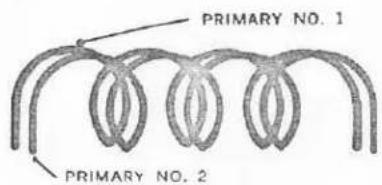
Figure 1. Representation of bifilar winding
The McIntosh output transformer is unique. It has two primary windings which are wound bifilarly. In the bifilar technique both primary wires are wound side by side. Each turn of primary number one is next to the same turn of primary number two, see figure 1. There is almost complete magnetic coupling between the two wires. The magnetic
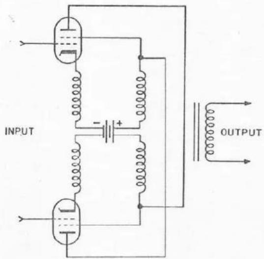
Figure 2. Representation of McIntosh output circuit
of the bifilar primary windings is connected through the power supply to the plate and cathode of one of the output tubes. The other bifilar primary winding is similarly connected to the other tube.
All low-distortion high-power amplifiers use push-pull output circuits known as Class AB 1 , AB 2 or B. Two tubes are arranged in a balanced circuit. This permits each tube to operate alternately somewhat over half the time. Compared to full time operation of the tubes, the push-pull method reduces heating and permits more power from a given type of tube. Despite this advantage of the conventional push-pull circuit one problem in particular remained to be solved. When current in each tube is cut off to begin the idle period distortion is produced at the instant of cut off and again at the instant when current flows. This form of distortion is known as Notch Distortion and was well illustrated by Mr. Pen Tung Sah in the “Proceedings of the I.R.E.” Volume 24, pp 1522-1541 in 1936.
Imperfect coupling between the primary windings found in all conventional output transformers produces the condition which permits notch distortion. Trying to improve coupling in a conventional transformer decreases the power response at both low and high frequencies, heating the output tubes and lowering the available power output.
The McIntosh Unity Coupled output circuit and bifilar transformer is the first commercial breakthrough that eliminates notch distortion by coupling both output tubes almost to perfection. In the McIntosh transformer the extremely close coupling of the cathode followers. Hall of the output circuit is in the cathode and half in the plate of each tube. The output tubes now are operating in a local feedback loop which, reduces their distortion, reduces their internal generator resistance, and reduces their balance requirements. The McIntosh circuit in reality perfects push-pull high efficiency output circuits.
The MC40 uses an advanced design of the McIntosh output transformer. The new transformer design incorporates all of the benefits of the original McIntosh design and even further improves the power band width.
Leakage inductance (lack of coupling) between the primary and secondary windings of the output transformer limits the high frequency response of an amplifier. The primary and secondary windings of the McIntosh output transformer are interleaved five times to improve coupling. The interleaving is accomplished by winding groups of primary layers, then secondary layers alternately until the total transformer is wound. Interleaving helps to extend the McIntosh power band width to over 100,000 cycles. Since 1947 this new technology has been built into every McIntosh power amplifier.
Good voltage regulation in the power supply permits overloads without overshoot or blocking, good transient response, and complete stability. To improve regulation a silicon rectifier power supply is used in the MC40. In addition to better voltage regulation, the silicon rectifier allows even higher operating efficiency, cooler operation, and longer amplifier life.
MECHANICAL SPECIFICATIONS
ELECTRICAL SPECIFICATIONS
Power Output
40 watts continuous
Harmonic Distortion
Less than 0.5% at 40 watts output or less, 20 cycles through 20,000 cycles. Typical performance is 0.3% or less for 20 cycles and 20,000 cycles at full power. Typical mid frequency performance is less than 0.1% at full power.
Intermodulation Distortion
Less than 0.5% for any combination of frequencies from 20 cycles through 20,000 cycles if instantaneous peak power is below 80 watts.
Phase Shift
Less than ±8^ 20 cycles through 20,000 cycles.
Frequency Range
At 40 watts output:
+0,-0.1 db 20 cycles through 20,000 cycles
+0, -0.5 db 16 cycles through 60,000 cycles
At 20 watts output:
+0, -1 db 10 cycles through 100 kilocycles
Noise and Hum
90 db or more below rated output
Output Impedance
4 ohms, 8 ohms, 16 ohms, 125 ohms, 150 ohms, and 600 ohms. The 4 ohm, 8 ohm, and 16 ohm outputs are isolated from ground for convenience in connecting speakers for stereo. The 600 ohm winding is balanced to ground and center tapped.
Output Voltages
25 volts and 70.7 volts.
Internal Impedance
Less than 10% of rated load impedance
Input
Input impedance—250,000 ohms
Input sensitivity—0.5 volts to 30 volts through gain control. 2.0 volts with gain control turned fully clockwise
Power Requirements
117 or 125 volts AC, 50/60 cps
Uses 145 watts at 40 watts output; 75 watts at zero signal output
Tube Complement
Voltage Amplifier 12AX7
Phase Inverter 12AU7
Drive Amplifier 12BH7
Cathode Follower Driver 12AX7
Output 2 each 6L6GC or 7027A
PANEL FACILITIES

Figure 3. End panel showing all input and output facilities
INPUT
The input jack marked 0.5 VOLT INPUT is located below the GAIN control.
The input sensitivity of the MC40 is 0.5 volt for 40 watts output. The input impedance is 250,000 ohms. There is a GAIN control in the input circuit to permit the use of input voltages up to 30 volts. In addition, turning the GAIN control (fully clockwise) operates a switch that changes the input sensitivity to 2.0 volts for 40 watts output. The 2.0 volt input position is for use with McIntosh pre-amplifiers.
SPEAKER OUTPUT
Output connections are provided on the barrier strip marked SPEAKER OUTPUT for the normal speaker impedances of 4 ohms, 8 ohms, and 16 ohms. They are also repeated at the octal socket marked OUTPUT. A ground connection marked GND has been provided on the barrier strip. The strap between the terminal marked GND and the terminal marked COM is provided to ground the secondary of the output transformer to the chassis for normal applications. If it is desirable to have the secondary of the output transformer feed a balanced line, the strap between the COM and GND terminals can be removed. McIntosh Amplifiers are designed to operate with the secondary of the output transformer either grounded or not grounded. The speaker output connections are fed from the secondary of the output transformer.
OUTPUT
The octal socket marked OUTPUT has connections for 4 ohms, 8 ohms, 16 ohms, 125 ohms, 150 ohms, or 600 ohms. The 600 ohms is balanced to ground.
The octal socket also has connections for constant voltages of 25 volts and 70.7 volts.
The 4 ohm, 8 ohm, and 16 ohm output terminals are fed from taps on the secondary winding of the output transformer. The 125 ohm, 150 ohm, and 600 ohm output terminals are fed from taps on cathode winding in the primary of the output transformer.
The 25 volt output is fed from a tap on the secondary of the output transformer. The 70.7 volt output is fed from taps on the cathode winding in the primary of the output transformer.
FUSE
The MC40 uses a 1.5 ampere slo-blo type fuse. The auxiliary AC socket is not fused.
AC OUTLET
The auxiliary AC outlet can be used to supply power to other equipment in the system. The outlet will provide a maximum of 400 watts of power. The AC outlet is not fused.
LINE VOLTAGE
The MC40 operates on line voltages between 105 volts to 130 volts, 50 cycles to 60 cycles. The switch marked LINE VOLTAGE changes the tap on the primary of the power transformer. The switch can be adjusted at any time.
INSTALLATION
VENTILATION
Adequate ventilation extends the trouble-free life of electronic instruments. It is generally found that each 10° centigrade (18° F) rise in temperature reduces the life of electrical insulation by one half. Adequate ventilation is an inexpensive and effective means of preventing insulation breakdown that results from unnecessarily high operating temperatures. The direct benefit of adequate ventilation is longer, more trouble-free life.
Always allow for air flow either by ventilation holes or space next to the bottom of the amplifier and a means for the warm air to escape at the top.
MOUNTING
The suggested minimum space for mounting the MC40 is 1712 " long x 10'' wide x 10'' high.
The MC40 can be mounted in any position except upside down. If the amplifier is to be installed on a vertical surface it is recommended that the transformers be on the down side. The advantage of this position is that the flow of heat from the tubes rises vertically and does not tend to heat the transformers.
If the MC40 is to be permanently mounted use the two mounting flanges supplied with the amplifier. The flanges are shipped separately and must be attached to the amplifier bottom at each end.
Turn the MC40 over with the transformers down and place it on a piece of cloth or cardboard to prevent scratches. The amplifier is shipped with 4 plastic feet on the bottom cover. Remove the 4 plastic feet. Remove the three self tapping screws at one end of the amplifier that holds the bottom cover to the chromium chassis. Place the square edge of the mounting flange with the three round holes positioned over the three holes in the bottom cover. Replace the three self tapping screws through the mounting flange and bottom cover into the amplifier chassis. The mounting flange is now firmly attached to the amplifier. The mounting flange on the other end of the amplifier is installed in the same way.

Figure 4. Bottom of MC40 with mounting flanges attached
Place the MC40 mounting template on the area where the amplifier is to be mounted. Center punch the mounting shelf through the 4 slotted holes in the mounting flanges shown on the template. Remove the template and install four #10 round head screws in the center punch marks. Do not tighten these screws. Place the amplifier over the screw heads and slide the amplifier to either side in the slotted holes of the mounting flanges. The #10 wood screws can then be tightened securely.
at the barrier strip or the octal socket. The barrier strip is usually more convenient.
In compliance with the National Electrical Code, Class II wiring can be used between the speaker and the amplifier at the 4 ohm, 8 ohm, or 16 ohm connection. Class II wiring is lamp cord, bell wire, or other wire with this type of insulation. For the normally short distances of under 100 feet between the amplifier and speaker, #18 wire or larger can be used. For distances over 100 feet between the amplifier and speaker use larger wire.
The loudspeaker impedance is usually identified on the speaker itself. Connect either one of the speaker leads to the screw on the barrier strip marked COM. Connect the other speaker lead to the screw on the barrier strip marked with the number corresponding to the speaker impedance.
The only adverse effect on the operation of a McIntosh amplifier when it is improperly matched is a reduction in the amount of distortion-free power available to the loudspeaker. Close impedance matching is desirable for maximum distortion-free power.
Use this table to determine proper speaker connections:
If the speaker
impedance
is between:
3.2 to 6.5 ohms
6.5 to 13 ohms
13 to 26 ohms
Connect the speaker
leads between
COM and:
4 ohms
8 ohms
16 ohms
The octal socket marked OUTPUT has connections for all of the MC40 output im-
between:
4 ohms Pin 1 and 2
8 ohms Pin 1 and 3
16 ohms Pin 1 and 4
125 ohms Pin 5 and 6
150 ohms Pin 6 and 7
600 ohms Pin 7 and 8
The 600 ohm winding is balanced. Pin 6 is the center tap of the 600 ohm winding and is ground.
For constant voltage applications use these connections:
Voltage required: Connect to:
25 volts Pin 1 and 4
70.7 volts Pin 5 and 6
For all applications using the 600 ohm or 70 volt outputs, use Class I wiring if the installation must meet the requirements of the National Electrical Code.
AC POWER
The MC40 operates on 105 volt to 130 volt, 50 to 60 cycle power. The amplifier will be turned on and off if its power cord is plugged in one of the auxiliary AC outlets on the program source.
FUSE
The MC40 is fused with a slo-blo type fuse rated at 1.5 amperes. For maximum protection always replace with fuses of the same rating, never larger. The AC outlet on the MC40 is not fused.
sockets. After the following adjustments have been completed the MC40 will operate without any further attention.
ADJUSTMENTS
LINE VOLTAGE
The LINE VOLTAGE switch should be set to the position that more closely matches the average line voltage in your area. The local electric power company can usually tell you the average line voltage in your area. If the line voltage is between 105 volts and 120 volts put the LINE VOLTAGE switch in the 117 volt position. If the line voltage is between 120 volts and 130 volts put the switch in the 125 volt position. If the line voltage is unknown, it is safer to operate with the switch in the 125 volt position.
GAIN
When using a monophonic McIntosh pre-amplifier turn the control above the input jack marked GAIN totally clockwise (to the right) to the position marked 2.0 V SETTING FOR McIntOSH PREAMP.
When using a stereophonic McIntosh pre-amplifier system turn the control above the input jack marked GAIN to the 12 o'clock position on both amplifiers. Adjust the GAIN control on one amplifier to one side or the other of the 12 o'clock position until equal amplitude is obtained from the amplifiers.
If the MC40 is to be used with any program
source other than a McIntosh preamplifier, the setting of this control should be adjusted to match the input voltage sensitivity of the MC40 to the output voltage of the program source.
For maximum flexibility set the amplifier gain control as follows; turn the volume control on the program source equipment (i.e. tape recorder, tuner, preamplifier other than McIntosh, etc.) to the 12 o'clock position. Turn the gain control on the MC40 until the loudness of the sound from the speaker is just a little louder than you normally like to listen. The volume control on the program source equipment now has the most convenient amount of loudness change in either direction from the 12 o'clock position.
IMPORTANT
The excellent performance that is inherent in all McIntosh amplifiers does not depend on the critical adjustment of controls in the output circuit. The patented McIntosh circuit delivers its advertised specifications without any need for these controls and is not dependent on carefully balanced tubes for its performance. With McIntosh you can install the amplifier and forget it.
Customer Service
McIntosh Laboratory Inc.
2 Chambers Street
Binghamton, New York
Our telephone number is 723-5491.
The direct dial area code is 607.
GUARANTEE
McIntosh Laboratory Incorporated guarantees this equipment to perform as advertised. We also guarantee the mechanical and electrical workmanship and components of this equipment to be free of defects for a
period of 90 days from date of purchase. This guarantee does not extend to components damaged by improper use nor does it extend to transportation to and from the factory.
3-YEAR FACTORY SERVICE CONTRACT
An application for a FREE 3-YEAR FACTORY SERVICE CONTRACT is included in the pocket in the back cover of this manual. The FREE 3-YEAR FACTORY SERVICE CONTRACT will be issued by McIntosh Laboratory upon receipt of the completely filled out application form. The term of this contract is defined
in the 3-year factory service contract. If the application is not mailed to McIntosh Laboratory, only the services offered under the standard 90-day guarantee will apply on this equipment. TAKE ADVANTAGE OF 3 YEARS OF FREE FACTORY SERVICE BY FILLING IN THE APPLICATION NOW.
In Canada: manufactured under license by:
McCurdy Radio Industries, Ltd.
- 22 Front Street West
Toronto, Canada

- MC40 POWER AMPLIFIER
- GENERAL DESCRIPTION
- TECHNICAL DESCRIPTION
- MECHANICAL SPECIFICATIONS
- ELECTRICAL SPECIFICATIONS
- Power Output
- Harmonic Distortion
- Intermodulation Distortion
- Phase Shift
- Frequency Range
- Noise and Hum
- Output Impedance
- Output Voltages
- Internal Impedance
- Input
- Power Requirements
- Tube Complement
- PANEL FACILITIES
- SPEAKER OUTPUT
- OUTPUT
- FUSE
- AC OUTLET
- LINE VOLTAGE
- INSTALLATION
- VENTILATION
- MOUNTING
- AC POWER
- ADJUSTMENTS
- GAIN
- IMPORTANT
- GUARANTEE
- 3-YEAR FACTORY SERVICE CONTRACT
Brand : MCINTOSH
Model : MC-40
Category : Audio Receiver