
MC-50 - Audio Receiver MCINTOSH - Free user manual and instructions
Find the device manual for free MC-50 MCINTOSH in PDF.


| Product Type | Audio Receiver |
| Brand | McIntosh |
| Model | MC-50 |
| Color | Black with silver knobs |
| Dimensions (W x H x D) | 17.5 in (44.5 cm) x 5.25 in (13.3 cm) x 15 in (38.1 cm) |
| Weight | 30 lb (13.6 kg) |
| Power Supply | 120 V, 60 Hz, 200 W |
| Power Output | 50 W per channel into 8 ohms (continuous) |
| Frequency Response | 20 Hz – 20 kHz ± 0.5 dB |
| Signal-to-Noise Ratio | 85 dB (IHF) |
| Total Harmonic Distortion | 0.05% at rated output |
| Inputs | Phono (MM), Tuner, Aux, Tape 1, Tape 2 |
| Outputs | Speaker A, Speaker B, Tape rec, Pre-out |
| Speaker Impedance | 4 to 16 ohms |
| Tone Controls | Bass ±12 dB at 50 Hz, Treble ±12 dB at 10 kHz |
| Tuner | FM/AM with analog dial, sensitivity 1.5 µV (FM) |
| Remote Control | Not included (optional external accessory) |
| Accessories | Power cord, user manual, warranty card |
| Safety | Do not expose to moisture; ensure adequate ventilation; unplug during storms |
| Maintenance | Clean with a dry cloth; avoid solvents; periodic dusting of vents |
| Repairability | Authorized service centers; genuine parts available |
Frequently Asked Questions - MC-50 MCINTOSH
User questions about MC-50 MCINTOSH
0 question about this device. Answer the ones you know or ask your own.
Ask a new question about this device
Download the instructions for your Audio Receiver in PDF format for free! Find your manual MC-50 - MCINTOSH and take your electronic device back in hand. On this page are published all the documents necessary for the use of your device. MC-50 by MCINTOSH.
USER MANUAL MC-50 MCINTOSH
natural_image
Illustration of a vintage intensification instrument labeled 'McIntosh 50' with control knobs and buttons (no readable text beyond label)McIntosh MC 50
McIntosh is the
Standard of Excellence because ....
The McIntosh "will to perfection" requires that we probe constantly into the unknown to bring the performance of our electronic equipment closer to perfection than ever before. This requires a constant and relentless search for low noise, broad band conservative design with an ever lower distortion factor. This is not required of ordinary equipment of average designs. It is, for us, a costly but worthwhile scientific and engineering effort. Our continuing research benefits our customers with the almost complete lack of obsolescence and the most reliable equipment ever made. It also means the lowest long-range cost to you. Nearly all of the McIntosh equipment ever made is still useable, or in use, though it may have been made twenty years ago.
CONTENTS
GENERAL DESCRIPTION 2
TECHNICAL DESCRIPTION 2-3
BLOCK DIAGRAM 4
SPECIFICATIONS 5
CONTROL PANEL INFORMATION 7
INSTALLATION 7
TYPICAL HOOKUP 8
CONNECTING 9
PERFORMANCE CHARTS 10
OPERATING 11
GUARANTEE 12
Thank You...
for purchasing the McIntosh MC 50. To insure your enjoyment please read this manual carefully and follow instructions. We know you will enjoy countless hours of musical pleasure from this instrument.
GENERAL DESCRIPTION
The dramatic difference in the quality of music reproduced through a McIntosh instrument is due to low distortion. The distortion of your MC 50 is guaranteed to be less than 0.25% at any frequency from 20Hz to 20kHz at 50 watts or less. Distortion is measured at full rated power output. At less than rated power, distortion becomes so small it can be measured only by the most sophisticated laboratory instruments. Only McIntosh gives you this kind of performance.
Your MC 50 passed more than 75 tests before it was ready for you. Each connection, wire, resistor, capacitor is checked and re-checked. All specifications are checked. McIntosh testing takes time. The extra investment in thorough testing assures you of greater musical enjoyment.
The performance of your McIntosh MC 50 is backed by a money back guarantee. Only McIntosh gives you a money back guarantee of performance. Your MC 50 must be capable of meeting its published specifications or you get a refund of your purchase price. McIntosh promises performance. We either meet our promise or you get your money back.
Your MC 50 can be protected by a free three year factory service contract. Take advantage of this service. Fill in the application card found in the owner's packet. The free three year factory service contract covers parts and labor. If anything goes wrong just bring your MC 50 to a factory service station, or return your MC 50 to McIntosh. All parts and labor necessary to repair your MC 50 will be supplied free of charge. Fill in the service contract application found in the owner's packet now.
TECHNICAL DESCRIPTION
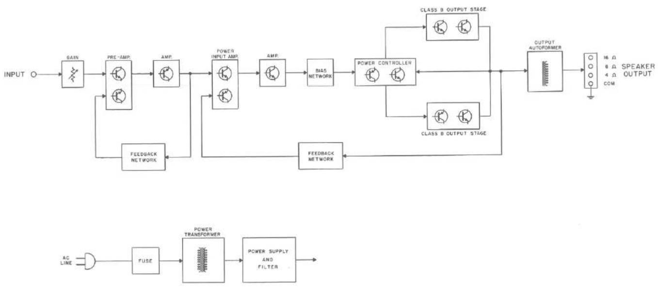
A two stage preamplifier with three transistors increases the input voltage 16 dB. The two stage preamplifier is fed to a pair of matched transistors arranged as an emmiter coupled amplifier with two inputs and one output. The signal from the preamplifier section connects to one of these inputs. Both AC and DC negative feedback are applied to the other input. This large quantity of feedback is used to reduce noise and distortion. The signal is then fed to a voltage amplifier. The voltage amplifier is followed by two driver transistors.
The output section is arranged as a series push-pull amplifier. The power transistors used in the output section of your MC 50 are selected for their high power dissipation capability, wide frequency response, and large "safe operating area." In addition, each power transistor is given four separate tests before it is put in your MC 50. This additional testing makes sure your MC 50 will deliver its rated power from 20 to 20 kHz with low distortion and complete reliability.
The power transistors are mounted on an oversized anodized heat sink. The extra large heat sink assures that under normal operation the transistors will operate at a low temperature. If temperatures increase due to a shorted speaker, or restricted ventilation, an automatic temperature sensing device turns off the MC 50. The device operates automatically at a preset temperature. The MC 50 will turn on again when the temperature has returned to normal limits. This additional feature gives your MC 50 complete reliability under the most extreme operating conditions.
The output stages are matched to the load by the McIntosh autoformer. The McIntosh autoformer is carefully wound using McIntosh trifilar winding and interleaving techniques. Trifilar winding and interleaving gives the transformers exceptional bandwidth. The autoformers properly matched the power transistors to 4, 8, and 16 ohm loads at all audio frequencies.
The use of the McIntosh designed trifilar autoformer makes the McIntosh solid state amplifiers the only amplifiers that deliver FULL POWER AT ALL SPEAKER IMPEDANCES. You have not been power penalized for your choice of loudspeakers when using the McIntosh MC 50.
Another of the advantages of the autoformer is the 25 volt output for a constant voltage distribution system. With the MC 50 several sets of speakers can be operated independently throughout your home.
To further insure reliability a special power output SENTRY MONITORING CIRCUIT prevents failure of the power output transistors due to excessive mismatch of the output. When your MC 50 operates normally the SENTRY MONITORING CIRCUIT has no effect on signals passing through the power amplifier. If the power dissipation should rise above normal operation, the SENTRY MONITORING CIRCUIT restricts the drive to the output transistors. The SENTRY MONITORING CIRCUIT acts instantaneously for any input signal or load combination. This arrangement assures complete circuit reliability. Only McIntosh gives you this degree of protection.
McIntosh
MC 50

natural_image
Illustration of a vintage MeIntosh 50 electronic device with control knobs and ventilation grilles (no readable text or symbols)POWER SUPPLY SECTION
There are three separate power supply sections. One positive and one negative high current supply is used for the output stages. The other positive supply is used for the driving amplifier stages. All supplies are full wave and use silicon rectifiers. Adequate filtering is used to assure an absolute minimum of hum. The power output stage filter capacitors have very high capacity, which allows full power output below 20 Hz. The power transformer is generous in size and runs cool, even under heavy use.
PERFORMANCE CHARTS

line
| FREQUENCY IN Hertz | POWER OUTNUT (Matts/Hz) - 0.2% Harmonic Distortion | POWER OUTNUT (Matts/Hz) - 3.1% Harmonic Distortion | | ------------------ | ---------------------------------------------------- | ---------------------------------------------------- | | 10 | ~30 | ~25 | | 30 | ~60 | ~55 | | 100 | ~60 | ~60 | | 500 | ~60 | ~60 | | 1K | ~60 | ~60 | | 8K | ~60 | ~60 | | 10K | ~60 | ~60 | | 50K | ~40 | ~35 | | 100K | ~10 | ~10 |
line
| POWER OUTPUT IN WATTS RMB | Percent Harmonic Distortion (20 kHz) | Percent Harmonic Distortion (2 kHz) | Percent Harmonic Distortion (21 kHz) | | ------------------------- | ------------------------------------- | ------------------------------------ | ------------------------------------- | | 1 | 0.0 | 0.0 | 0.0 | | 70 | 0.0 | 0.0 | 0.0 | | 30 | 0.0 | 0.0 | 0.0 | | 60 | 0.0 | 0.0 | 0.0 | | 90 | 0.0 | 0.0 | 0.0 | | 120 | 0.0 | 0.0 | 0.0 | | 150 | 0.0 | 0.0 | 0.0 | | 180 | 0.0 | 0.0 | 0.0 | | 210 | 0.0 | 0.0 | 0.0 | | 240 | 0.0 | 0.0 | 0.0 | | 270 | 0.0 | 0.0 | 0.0 | | 300 | 0.0 | 0.0 | 0.0 | | 330 | 0.0 | 0.0 | 0.0 | | 360 | 0.0 | 0.0 | 0.0 | | 390 | 0.0 | 0.0 | 0.0 | | 420 | 0.0 | 0.0 | 0.0 | | 450 | 0.0 | 0.0 | 0.0 | | 480 | 0.0 | 0.0 | 0.0 | | 510 | 0.0 | 0.0 | 0.0 | | 540 | 0.0 | 0.0 | 0.0 | | 570 | 0.0 | 0.0 | 0.0 | | 600 | 1.5 | 1.5 | 1.5 | | 630 | 3.5 | 3.5 | 3.5 | | 660 | 5.5 | 5.5 | 5.5 | | 690 | 7.5 | 7.5 | 7.5 | | 720 | 9.5 | 9.5 | 9.5 | | 750 | 11.5 | 11.5 | 11.5 | | 780 | 13.5 | 13.5 | 13.5 | | 810 | 15.5 | 15.5 | 15.5 | | 840 | 17.5 | 17.5 | 17.5 | | 870 | 19.5 | 19.5 | 19.5 | | 900 | 21.5 | 21.5 | 21.5 | | 930 | 23.5 | 23.5 | 23.5 | | 960 | 25.5 | 25.5 | 25.5 | | 990 | 27.5 | 27.5 | 27.5 | | 1244 | - | - | - | | Total | - | - | - |
line
| POWER OUTPUT EQUIVALENT WATTS RMS | PERCENT INTERMODULATION DISTORTION | | ---------------------------------- | ------------------------------------ | | 1 | 0.5 | | 10 | 0.5 | | 20 | 0.5 | | 30 | 0.5 | | 40 | 0.5 | | 50 | 0.5 | | 60 | 0.5 | | 70 | 0.5 | | 80 | 0.5 | | 90 | 0.5 | | 100 | 0.5 |SPECIFICATIONS
MC 50
ELECTRICAL SPECIFICATIONS:
POWER OUTPUT:
50 RMS watts continuous into 4, 8, or 16 ohms.
HARMONIC DISTORTION:
Less than 0.25% at 50 watts power output from 20 Hz to 20 kHz. Typical performance is less than 0.1% at rated power. Distortion decreases as output power is reduced.
INTERMODULATION DISTORTION:
Less than 0.25% if instantaneous peak power output is 100 watts or less for any combination of frequencies 20 Hz and 20 kHz.
FREQUENCY RESPONSE:
20 Hz to 20 kHz +0, -0.1 dB at 50 watts 10 Hz to 50 kHz +0, -0.5 dB at 50 watts 7 Hz to 100 kHz +0, -3.0 dB at 25 watts
NOISE AND HUM:
90 dB or more below rated output.
OUTPUT IMPEDANCE:
4, 8, and 16 ohms.
OUTPUT VOLTAGES:
25 volts
DAMPING FACTOR:
25 at 4 ohms output 50 at 8 ohms output 17 at 16 ohms output
INPUT IMPEDANCE:
200,000 ohms
INPUT SENSITIVITY:
0.5 volts. Level control provided for higher input voltage.
POWER REQUIREMENTS:
117 volts AC 50/60 Hz, 15 watts at zero signal output, 120 watts at 50 watts output.
SEMICONDUCTOR COMPLEMENT:
12 Silicon Transistors 12 Silicon Rectifiers and Diodes
MECHANICAL SPECIFICATIONS:
SIZE: 5½ inches high, 8 inches wide, 12½ inches deep.
CHASSIS: Chrome and black.
WEIGHT: 20 pounds net, 24 pounds in shipping carton.
SPECIAL FEATURES
The amplifier is completely stable when connected to any loudspeaker system or to any reactive load. The MC 50 has special circuits to prevent damage by short circuit or open circuit of the output loads, or by any amount of output impedance mismatch.
Thermal cutouts are mounted on the output transistor heat sinks to provide protection in the event of inadequate ventilation.

natural_image
Illustration of a Intosh 50 electronic device with heat sinks and control knobs (no readable text or symbols beyond branding)CONTROL PANEL INFORMATION

INPUT
The input jack is located below the GAIN control.
The input sensitivity of the MC 50 is 0.5 volt for 50 watts output. The input impedance is 200,000 ohms. There is a GAIN control in the input circuit to permit the use of input voltages up to 30 volts.
OUTPUT
Output connections are provided on the output barrier strip for the normal speaker impedances of 4 ohms, 8 ohms, and 16 ohms. Connection at the terminal strips may be made for a constant voltage output of 25 volts.
FUSE
The MC 50 uses a 1.5 ampere slo-blo type fuse. The auxiliary AC outlet is not fused.
AC OUTLET
The auxiliary AC outlet can be used to supply power to other equipment in the system. The outlet will provide a maximum of 400 watts of power. The AC outlet is not fused.
LINE VOLTAGE
The MC 50 operates on any line voltages between 117 volts and 130 volts, 50 to 60 Hz.
AC POWER
The MC 50 operates on 117 to 130 volt, 50/60 Hz. The amplifier will be turned on and off if its power cord is plugged in one of the auxiliary AC outlets on the program source.
INSTALLATION
Adequate ventilation extends the trouble-free life of electronic instruments. It is generally found that each 10° centigrade (18° F) rise in temperature reduces the life of electrical insulation by one half. Adequate ventilation is an inexpensive and effective means of preventing insulation breakdown that results from unnecessarily high operating temperatures. The direct benefit of adequate ventilation is longer, trouble-free life.
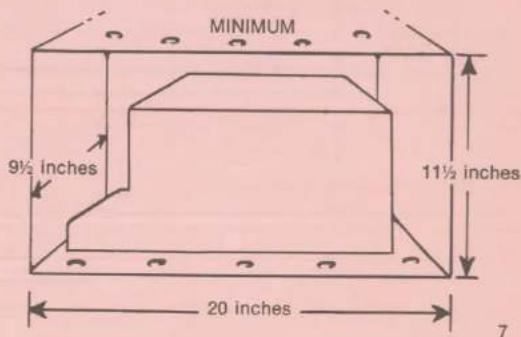
The suggested minimum space for mounting the MC 50 is 20 inches long x 9½ inches wide x 11½ inches high. Always allow for air flow by either ventilation holes or space next to the bottom of the amplifier and a means for the warm air to escape at the top.
It is recommended that the MC 50 be mounted in a normal or horizontal position. However with adequate ventilation the amplifier can be mounted in any position except upside down. If the amplifier is to be installed on a vertical surface it is recommended that the autoformers be on the down side. This position permits greater air flow around the transistors and component parts thereby extending the trouble-free life of the amplifier.
TYPICAL HOOK UP

flowchart
graph TD
    A["REMOTE MONOPHONIC SPEAKER"] --> B["MC 50 CENTER CHANNEL AMPLIFIER"]
    C["LEFT MAIN SPEAKER"] --> B
    D["CENTER CHANNEL SPEAKER"] --> B
    E["RIGHT MAIN SPEAKER"] --> B
    F["LEFT REMOTE SPEAKER"] --> G["PREAMPLIFIER"]
    H["RIGHT REMOTE SPEAKER"] --> G
    B --> I["MC 50 LEFT CHANNEL AMPLIFIER"]
    B --> J["MC 50 RIGHT CHANNEL AMPLIFIER"]
    G --> K["Divitout"]
    G --> L["AC LINE"]
    G --> M["AG LINE"]
    G --> N["AG LINE"]
    G --> O["PREAMPLIFIER"]
    style A fill:#f9f,stroke:#333
    style C fill:#f9f,stroke:#333
    style D fill:#f9f,stroke:#333
    style E fill:#f9f,stroke:#333
    style F fill:#f9f,stroke:#333
    style H fill:#f9f,stroke:#333
    style G fill:#ccf,stroke:#333
    style I fill:#dfd,stroke:#333
    style J fill:#dfd,stroke:#333
    style K fill:#dfd,stroke:#333
    style L fill:#dfd,stroke:#333
    style M fill:#dfd,stroke:#333
    style N fill:#dfd,stroke:#333
CONNECTING THE MC50

INPUT The shielded cable from the program source is plugged into the INPUT jack.
OUTPUT Speakers are connected at the output barrier strip on the sloped panel of the amplifier. Use lamp cord, bell wire, or wire with similar type of insulation to connect the speakers to the amplifier. For the normally short distances of under 50 feet between the amplifier and speaker, #18 wire or larger can be used. For distances over 50 feet between the amplifier and speaker use larger wire.
The loudspeaker impedance is usually identified
on the loudspeaker itself. Connect one lead from the loudspeaker to the screw marked COM on the OUTPUT barrier strip. Connect the other lead from the loudspeaker to the screw marked with the number corresponding to the speaker impedance on the OUTPUT barrier strip.
The only adverse effect on the operation of a McIntosh amplifier when it is improperly matched is a reduction in the amount of distortion-free power available to the loudspeaker. Close impedance matching is desirable for maximum distortion-free power.
Use this table to determine proper speaker connection:
| If the speaker impedance is between: | Connect the speaker leads between COM and: |
| 3.2 to 6.5 ohms | 4 ohms |
| 6.5 to 13 ohms | 8 ohms |
| 13 to 26 ohms | 16 ohms |
BLOCK DIAGRAM MC 50
flowchart
graph LR
    A["INPUT"] --> B["GAIN"]
    B --> C["PRE-AMP"]
    C --> D["AMR"]
    D --> E["POWER INPUT AMP"]
    E --> F["AMR"]
    F --> G["BIAS NETWORK"]
    G --> H["POWER CONTROLLER"]
    H --> I["OUTPUT AUTOFORMER"]
    I --> J["SPEAKER OUTPUT"]

    K["AC LINE"] --> L["FUSE"]
    L --> M["POWER TRANSFORMER"]
    M --> N["POWER SUPPLY AND FILTER"]

    O["FEEDBACK NETWORK"] --> P["Feedback Network"]
    P --> Q["POWER INPUT AMP"]
    Q --> R["AMR"]
    R --> S["BIAS NETWORK"]
    S --> T["POWER CONTROLLER"]
    T --> U["OUTPUT AUTOFORMER"]
    U --> V["SPEAKER OUTPUT"]

    W["CLASS B OUTPUT STAGE"] --> X["OUTPUT AUTOFORMER"]
    Y["CLASS B OUTPUT STAGE"] --> Z["OUTPUT AUTOFORMER"]
    AA["16 Ω 8 Ω 4 Ω COM"] --> AB["SPEAKER OUTPUT"]
OPERATING THE MC50 STEREO AMPLIFIER
SETTING THE GAIN CONTROL:
Turn the volume control on the source equipment to the 12 o'clock position (half rotation). Turn up the GAIN control on the MC 50 until the loudness in the room is about as loud as you like to listen. This setting allows the volume control on the source equipment the greatest range of operation and loudness change.
natural_image
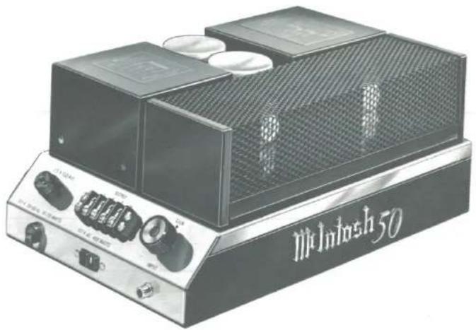
Illustration of a MiIntosh 50 electronic device with control knobs and a mesh chamber (no readable text or symbols beyond branding)Now sit back and enjoy your McIntosh!
Your MC 50 power amplifier will give you many years of pleasant and satisfactory performance. If you have any questions concerning operation or maintenance please contact the dealer from whom you purchased this instrument or: —
MC50 GUARANTEE
McIntosh Laboratory Incorporated guarantees this equipment to be capable of performance as advertised. We also guarantee the mechanical and electrical workmanship and components of this equipment to be free of defects for a period of 90 days from date of purchase. This guarantee does not extend to components damaged by improper use nor does it extend to transportation to and from the factory.
3 YEAR FACTORY SERVICE CONTRACT
An application for a FREE 3 YEAR FACTORY SERVICE CONTRACT is included in the pack with this manual. The FREE 3 YEAR FACTORY SERVICE CONTRACT will be issued by McIntosh Laboratory upon receipt of the completely filled out application form. The terms of the contract are:
- Transportation charges are excluded.
- This agreement is given to the original purchaser only and is not transferable.
- The application for the contract must be filled out completely
- If the instrument has been modified or damaged by unauthorized repair the contract will be cancelled.
- To receive free service, the contract must be presented to the factory authorized service agency, when the equipment is presented for repair.
If the application is not received at McIntosh Laboratory, only the service offered under the standard 90 day guarantee will apply on this equipment.
CUSTOMER SERVICE
McIntosh Laboratory Inc.
2 Chambers Street
Binghamton, N. Y. 13903
Our telephone number is
607-723-3512
McIntosh
MC 50
2 CHAMBERS ST., BINGHAMTON, N. Y. 13903
607-723-3512
Design subject to change without notice.
Printed in USA

- McIntosh is the
- Standard of Excellence because ....
- CONTENTS
- Thank You...
- GENERAL DESCRIPTION
- TECHNICAL DESCRIPTION
- POWER SUPPLY SECTION
- PERFORMANCE CHARTS
- SPECIFICATIONS
- MC 50
- ELECTRICAL SPECIFICATIONS:
- POWER OUTPUT:
- HARMONIC DISTORTION:
- INTERMODULATION DISTORTION:
- FREQUENCY RESPONSE:
- NOISE AND HUM:
- OUTPUT IMPEDANCE:
- OUTPUT VOLTAGES:
- DAMPING FACTOR:
- INPUT IMPEDANCE:
- INPUT SENSITIVITY:
- POWER REQUIREMENTS:
- SEMICONDUCTOR COMPLEMENT:
- MECHANICAL SPECIFICATIONS:
- SPECIAL FEATURES
- CONTROL PANEL INFORMATION
- INPUT
- OUTPUT
- FUSE
- AC OUTLET
- LINE VOLTAGE
- AC POWER
- INSTALLATION
- CONNECTING THE MC50
- OPERATING THE MC50 STEREO AMPLIFIER
- SETTING THE GAIN CONTROL:
- MC50 GUARANTEE
- YEAR FACTORY SERVICE CONTRACT
- CUSTOMER SERVICE
Brand : MCINTOSH
Model : MC-50
Category : Audio Receiver