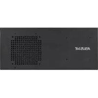
EBS-A710 - Industrial computer ASUS - Free user manual and instructions
Find the device manual for free EBS-A710 ASUS in PDF.


| Product Type | Industrial Computer Barebone |
| Model | EBS-A710 |
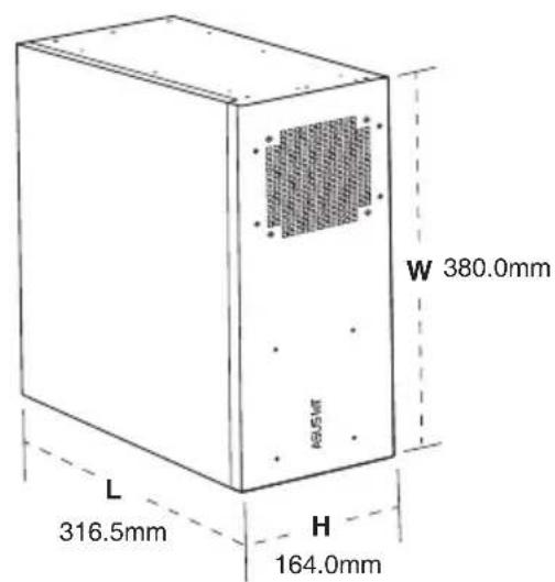
| Dimensions (W x D x H) | 316.5 x 380.0 x 164.0 mm |
| Net Weight | Approx. 6.5 kg (estimated) |
| Form Factor | Mini tower / box PC |
| Chassis Material | SGCC sheet metal (1.2 mm) |
| Color | Black |
| Power Supply | 100-240V~, 4.0A, 50-60Hz; internal industrial PSU |
| CPU Support | Intel 9th/8th Gen Core i7/i5/i3, Pentium, Celeron (LGA1151) |
| Memory | 2 x DDR4 DIMM slots, up to 64 GB, 3200 MHz |
| Storage | 4 x SATA 6Gb/s; 1 x M.2 socket 3 (M key, 2242/2260/2280) |
| Expansion Slots | 1 x PCIe x16, 3 x PCIe x4, 3 x PCI |
| Rear I/O Ports | 1 x DisplayPort, 2 x HDMI, 1 x VGA, 2 x LAN (RJ45), 2 x USB 3.2 Gen1, 2 x USB 2.0, 2x COM (RS232/422/485), Audio jacks |
| Front I/O Ports | Optional USB 2.0, optional serial ports, power/reset buttons, LED indicators |
| Internal Connectors | USB 2.0 headers, COM headers, LPT, GPIO, TPM, chassis intrusion |
| BIOS Features | AMI UEFI BIOS with Ai Tweaker, advanced power management, secure boot |
| Operating Temperature | 0 to 40°C |
| Storage Temperature | -15 to 60°C |
| Relative Humidity | 10% to 95% @40°C non-condensing |
| OS Support | Windows 10 (64-bit), Windows 10 IoT Enterprise, Ubuntu, RedHat, Fedora |
| Safety Features | Chassis intrusion detection, TPM header, lithium battery warning |
| Mounting | Bottom brackets with M4 screws (included) |
| Cooling | CPU fan header, chassis fan header, PSU fan vent |
Frequently Asked Questions - EBS-A710 ASUS
User questions about EBS-A710 ASUS
0 question about this device. Answer the ones you know or ask your own.
Ask a new question about this device
Download the instructions for your Industrial computer in PDF format for free! Find your manual EBS-A710 - ASUS and take your electronic device back in hand. On this page are published all the documents necessary for the use of your device. EBS-A710 by ASUS.
USER MANUAL EBS-A710 ASUS
(Industrial Computer Barebone)
User's Manual
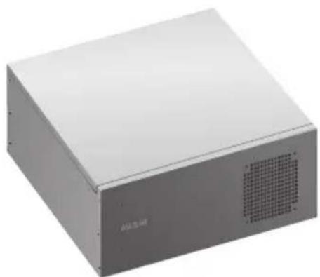
natural_image
Exterior view of a gray rectangular electronic device with ventilation grille and label (no readable text or symbols)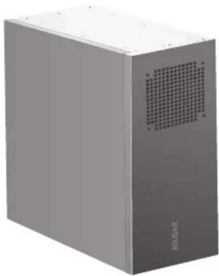
natural_image
Exterior view of a gray industrial enclosure with ventilation grille and 'KESM' branding (no other text or symbols visible)EBS-A710
E23230
First Edition
March 2024
Copyright © 2024 ASUSTeK Computer Inc. All Rights Reserved.
No part of this manual, including the products and software described in it, may be reproduced, transmitted, transcribed, stored in a retrieval system, or translated into any language in any form or by any means, except documentation kept by the purchaser for backup purposes, without the express written permission of ASUSTeK Computer Inc. ("ASUS").
Product warranty or service will not be extended if: (1) the product is repaired, modified or altered, unless such repair, modification of alteration is authorized in writing by ASUS; or (2) the serial number of the product is defaced or missing.
ASUS PROVIDES THIS MANUAL "AS IS" WITHOUT WARRANTY OF ANY KIND, EITHER EXPRESS OR IMPLIED, INCLUDING BUT NOT LIMITED TO THE IMPLIED WARRANTIES OR CONDITIONS OF MERCHANTABILITY OR FITNESS FOR A PARTICULAR PURPOSE. IN NO EVENT SHALL ASUS, ITS DIRECTORS, OFFICERS, EMPLOYEES OR AGENTS BE LIABLE FOR ANY INDIRECT, SPECIAL, INCIDENTAL, OR CONSEQUENTIAL DAMAGES (INCLUDING DAMAGES FOR LOSS OF PROFITS, LOSS OF BUSINESS, LOSS OF USE OR DATA, INTERRUPTION OF BUSINESS AND THE LIKE), EVEN IF ASUS HAS BEEN ADVISED OF THE POSSIBILITY OF SUCH DAMAGES ARISING FROM ANY DEFECT OR ERROR IN THIS MANUAL OR PRODUCT.
SPECIFICATIONS AND INFORMATION CONTAINED IN THIS MANUAL ARE FURNISHED FOR INFORMATIONAL USE ONLY, AND ARE SUBJECT TO CHANGE AT ANY TIME WITHOUT NOTICE, AND SHOULD NOT BE CONSTRUED AS A COMMITMENT BY ASUS. ASUS ASSUMES NO RESPONSIBILITY OR LIABILITY FOR ANY ERRORS OR INACCURACIES THAT MAY APPEAR IN THIS MANUAL, INCLUDING THE PRODUCTS AND SOFTWARE DESCRIBED IN IT.
Products and corporate names appearing in this manual may or may not be registered trademarks or copyrights of their respective companies, and are used only for identification or explanation and to the owners' benefit, without intent to infringe.
Table of contents
Safety information....v
About this guide....vi
System package contents......viii
Chapter 1 System introduction
1.1 Welcome! 1-2
1.2 Brief introduction 1-2
1.3 Front panel and rear panel.... 1-4
1.4 Internal components.... 1-7
1.5 Mounting the chassis.... 1-8
Chapter 2 Motherboard information
2.1 Motherboard layout 2-2
2.2 Central Processing Unit (CPU) 2-4
2.3 System memory 2-4
2.4 Jumpers.... 2-5
2.5 Internal connectors.... 2-7
2.6 Slots 2-16
Chapter 3 BIOS setup
3.1 BIOS setup program.... 3-2
3.1.1 BIOS menu screen 3-3
3.2 Main menu.... 3-3
3.2.1 Language [English]....3-3
3.2.2 System Date [Day MM/DD/YYYY]....3-3
3.2.3 System Time [HH:MM:SS] 3-3
3.2.4 Security 3-3
3.3 Ai Tweaker menu 3-5
3.3.1 CPU Power Enhancement 3-5
3.3.2 CPU Core Ratio....3-5
3.3.3 DRAM Odd Ratio Mode....3-6
3.3.4 DRAM Frequency....3-6
3.3.5 Power-saving & Performance Mode....3-7
3.3.6 DRAM Timing Control 3-7
3.3.7 DIGI+ VRM 3-14
3.3.8 Internal CPU Power Management....3-15
3.3.9 CPU Core/Cache Current Limit Max. 3-16
Table of contents
3.3.10 CPU Graphics Current Limit....3-16
3.3.11 Min. CPU Cache Ratio 3-16
3.3.12 Max. CPU Cache Ratio 3-16
3.3.13 Max. CPU Graphics Ratio 3-16
3.3.14 DRAM Voltage....3-16
3.3.15 DRAM REF Voltage Control....3-16
3.4 Advanced menu 3-17
3.4.1 Platform Misc Configuration 3-17
3.4.2 CPU Configuration 3-18
3.4.3 System Agent (SA) Configuration 3-20
3.4.4 PCH Configuration 3-21
3.4.5 PCH Storage Configuration.... 3-21
3.4.6 PCH-FW Configuration.... 3-22
3.4.7 Onboard Devices Configuration 3-22
3.4.8 APM Configuration 3-25
3.4.9 Serial Console Redirection....3-26
3.4.10 PCI Subsystem Settings....3-28
3.4.11 USB Configuration.... 3-28
3.4.12 Network Stack Configuration.... 3-28
3.4.13 HDD Secure Erase....3-29
3.4.14 HDD/SSD SMART Information....3-29
3.5 Monitor menu 3-29
3.6 Boot menu.... 3-33
3.7 Tool menu 3-38
3.8 Exit menu 3-38
Appendix
Notices....A-1
Service and Support....A-5
Safety information
Electrical safety
- To prevent electric shock hazard, disconnect the power cable from the electric outlet before relocating the system.
- When adding or removing devices to or from the system, ensure that the power cables for the devices are unplugged before the signal cables are connected. If possible, disconnect all power cables from the existing system before you add a device.
- Before connecting or removing signal cables from the motherboard, ensure that all power cables are unplugged.
- Seek professional assistance before using an adapter or extension cord. These devices could interrupt the grounding circuit.
- Ensure that your power supply is set to the correct voltage in your area. If you are not sure about the voltage of the electrical outlet you are using, contact your local power company.
- If the power supply is broken, do not try to fix it by yourself. Contact a qualified service technician or your retailer.
Operation safety
- Before installing the motherboard and adding devices on it, carefully read all the manuals that came with the package.
- Before using the product, ensure that all cables are correctly connected and the power cables are not damaged. If you detect any damage, contact your dealer immediately.
- To avoid short circuits, keep paper clips, screws, and staples away from connectors, slots, sockets and circuitry.
- Avoid dust, humidity, and temperature extremes. Do not place the product in any area where it may become wet.
- Place the product on a stable surface.
- If you encounter technical problems with the product, contact a qualified service technician or your retailer.
WARNING: For safety purposes, ONLY connect the power cord to a grounded electrical outlet.
Lithium-Ion Battery Warning
CAUTION: Danger of explosion if battery is incorrectly replaced. Replace only with the same or equivalent type recommended by the manufacturer. Dispose of used batteries according to the manufacturer's instructions.
LASER PRODUCT WARNING
CLASS 1 LASER PRODUCT
Restricted Access Location
This product is intended for installation only in a Computer Room where:
- Access can only be gained by SERVICE PERSONS or by USERS who have been instructed about the reasons for the restrictions applied to the location and about any precautions that shall be taken.
- Access is through the use of a TOOL, or other means of security, and is controlled by the authority responsible for the location.
- Only skilled persons open cover.
About this guide
Audience
This guide provides general information and installation instructions about ASUS EBS-A710 IPC system. This guide is intended for users and administrators with experience handling hardware and PC components.
How this guide is organized
This guide contains the following parts:
1. Chapter 1: System introduction
This chapter gives a general description of ASUS EBS-A710. The chapter lists system features, physical descriptions of the front and rear panels, and an overview of internal components.
2. Chapter 2: Motherboard info
This chapter provides details about the motherboard that comes with the system. This chapter includes the motherboard layout, jumper settings, and connector locations.
3. Chapter 3: BIOS setup
This chapter provides a detailed guide to navigating and setting up the BIOS.
Conventions used in this guide

CAUTION: Indicates information to prevent damage to the components when completing a task.

IMPORTANT: Instructions that you MUST follow to complete a task.

NOTE: Tips and additional information when completing a task.
Where to find more information
Refer to the following sources for additional information and for product and software updates.
1. ASUS Website
The ASUS website worldwide provides updated information on ASUS hardware and software products. Refer to the ASUS contact information.
2. Optional Documentation
Your product package may include optional documentation, such as warranty flyers, that may have been added by your dealer. These documents are not part of the standard package.
System package contents
Check your EBS-A710 system package for the following items.

If any of the items is damaged or missing, contact your retailer immediately.
| Item Description |
| 1. ASUS EBS-A710 industrial computer system with |
| • ASUS industrial motherboard (H310A-EM-A) |
| • Industrial power supply unit |
| • Chassis with 1.2mm durable SGCC sheet metal |
| • 1 x M.2 screw |
| • 1 accessory box (labeled with P/N: 13AE0060Mxxxxx), including screws and clamp hooks |
| 2. Cables |
| • Power SW cable |
| • SATA 6G cable |
| 3. Quick Installation Guide |
Chapter 1
This chapter gives a general description of ASUS EBS-A710. The chapter lists system features, physical descriptions of the front and rear panels, and an overview of internal components.

natural_image
Line drawing of a rectangular electronic device with a grid pattern on the side panel (no text or symbols)The illustrations in this user manual are for reference only. Actual product may vary.
1.1 Welcome!
Thank you for choosing the ASUS EBS-A710!
The ASUS EBS-A710 provides cutting-edge performance and uncompromised reliability for industrial use.
The system is powered by the ASUS motherboard that supports the Intel® 9 ^th /8 ^th Gen. Core™ i7 / i5 / i3, Pentium® and Celeron® processors in the Intel® socket 1151.
The system supports up to 64GB of system memory using DDR4 3200 MHz DIMMs. High resolution graphics via PCI Express x16 slots, SATA 6.0Gb/s, USB 3.2 Gen 1 ports, and USB 2.0 ports take you ahead in the world of power computing.
1.2 Brief introduction
• Color: Black (EBS-A710)
• Net weight: refer to the data sheet
• Form factor: 316.5mm x 380.0 mm x 164.0mm

• Operation temperature: 0\~40°C
• Non-operation temperature: -15\~60°C
- Relative humidity:10\~95%@40°C,non-condensing
- OS support:
Windows® 10 (64bit)
Windows® 10 IoT Enterprise
Ubuntu
RedHat Enterprise
Fedora Workstation
| Main components | |
 |  |
| Chassis | Motherboard (ASUS H310A-EM-A) |
 |  |
| Power supply unit | Accessory box |
1.3 Front panel and rear panel
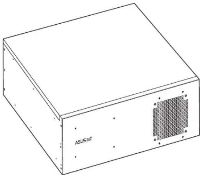
natural_image
Line drawing of a rectangular electronic device with a grid pattern on the side panel and 'ASUS left' label (no other text or symbols)The system rear panel includes the power connector and several I/O ports that allow convenient connection of devices.
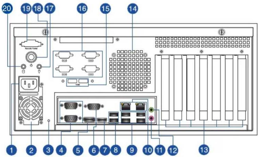
- Power connector. Plug the power cord to this connector.

RATING: 100-240V\~, 4.0A, 50-60Hz (China)
-
Power supply unit fan vent. This vent is for the PSU fan that provides ventilation inside the power supply unit.
-
Reset button. Press this button to reset the system.
-
COM ports (COM, RS232/RS422/RS485). These ports connect modems, or other devices that conform with serial specification.
| RS232 RS485 RS422 | |||
| Pin1 | DCD | B T(B) | |
| Pin2 | RXD | A T(A) | |
| Pin3 | TXD | NC R(A) | |
| Pin4 | DTR | NC R(B) | |
| Pin5 | GND | GND GND | |
| Pin6 | DSR | NC NC | |
| Pin7 | RTS | NC NC | |
| Pin8 | CTS | NC NC | |
| Pin9 | R/5V/12V | NC/5V/12V | NC/5V/12V |
-
DisplayPort. This port is for a DisplayPort-compatible device.
-
HDMI™ ports. These ports are for a High-Definition Multimedia Interface (HDMI™) connector, and are HDCP compliant allowing playback of HD DVD, Blu-ray, and other protected content.
-
Video Graphics Adapter (VGA) port. This 15-pin port is for a VGA monitor or other VGA-compatible device.
-
USB 2.0 ports. These 4-pin Universal Serial Bus (USB) ports are for USB 2.0 devices.
-
USB 3.2 Gen 1 (up to 5Gbps) ports. These 9-pin Universal Serial Bus (USB) ports are for USB 3.2 Gen 1 devices.
-
LAN (RJ-45) ports. These ports allow Gigabit connection to a Local Area Network (LAN) through a network hub.
LAN port LED indications
| Active LED | Link LED | ||
| Status | Description | Status | Description |
| OFF No link | OFF | 10Mbps connection | |
| ORANGE | Linked | ORANGE | 100Mbps connection |
| BLINKING | Data activity | GREEN | 1Gbps connection |

-
Microphone port (pink). This port connects to a microphone.
-
Line Out port (lime). This port connects to a headphone or a speaker. In the 4.1, and 5.1 channel configurations, the function of this port becomes Front Speaker Out.
- Expansion slot brackets. Remove the expansion slot bracket when installing an expansion card.
- Air vents. These vents allow air ventilation.

DO NOT block the air vents on the chassis. Always provide proper ventilation for your computer.
- USB 2.0 ports (optional). These 4-pin Universal Serial Bus (USB) ports are for USB 2.0 devices.
- Serial ports (optional). These 9-pin COM ports are for pointing devices or other serial devices.
- Power LED. The LED lights up or blinks to indicate the status of the system power.
- Power button. Press this button to turn the system on.
- Remote power port (optional).
- HDD LED. The LED lights up or blinks to indicate the status of the HDD.
1.4 Internal components
The illustration below is the internal view of the system when you remove the chassis cover and the power supply unit. The installed components are labeled for your reference.

- Power supply unit
- ASUS motherboard
- Metal bracket
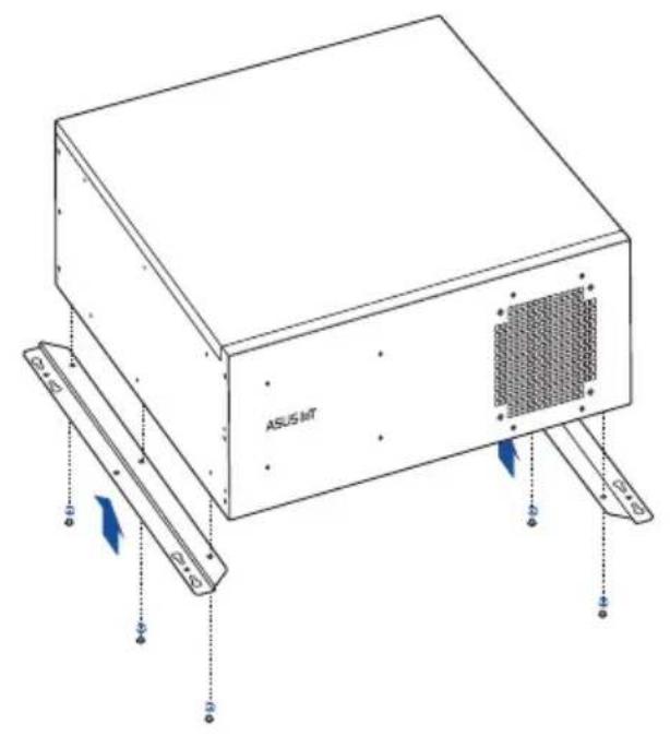
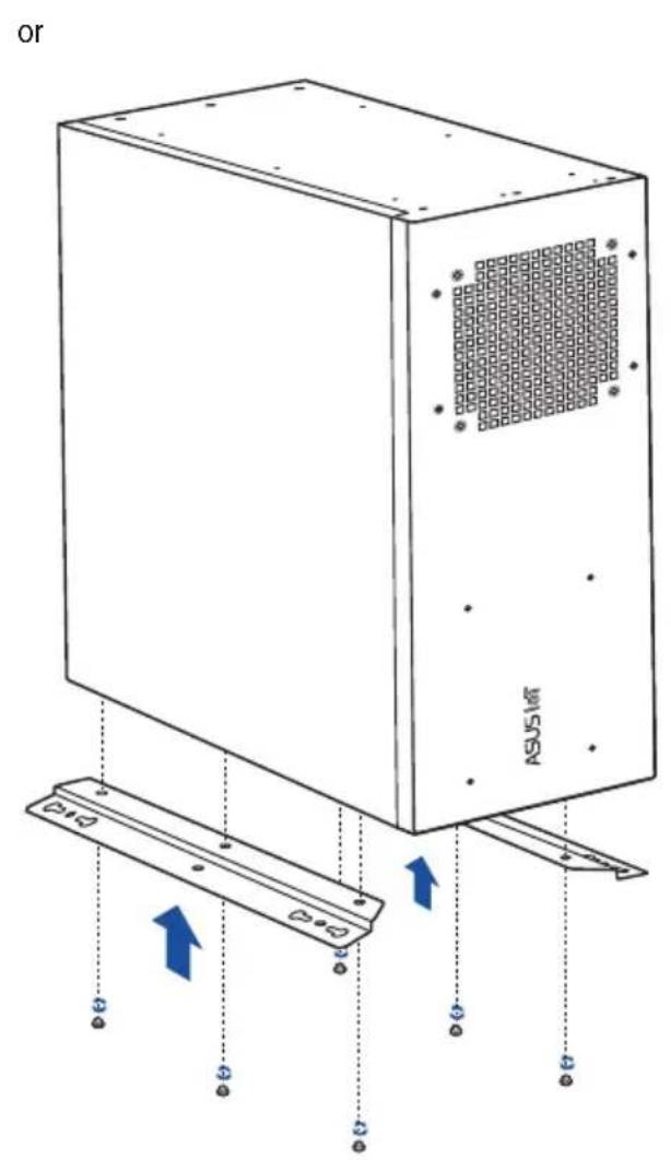
1.5 Mounting the chassis
Attach the brackets to the bottom side of the chassis with the bundled screws (6 * M4.0 x 6L).
Chapter 2
This chapter provides details about the motherboard that comes with the system. This chapter includes the motherboard layout, jumper settings, and connector locations.

natural_image
Line drawing of a rectangular electronic device labeled 'ASUS IoT' with a grid-patterned side panel (no text beyond label)2.1 Motherboard layout

| Connectors/Jumpers/Slots Page | |
| 1. COM1 Ring/+5V/+12V Selection jumpers (6-pin COM1_ESL, COM2_ESL) 2-12 | |
| 2. ATX Power connectors (24-pin EATXPWR, 4-pin ATX12V) 2-24 | |
| 3. CPU and Chassis Fan headers (4-pin CPU_FAN, 4-pin CHA_FAN) 2-18 | |
| 4. Intel ® LGA1151 CPU socket 2-4 | |
| 5. M.2 socket 3 2-21 | |
| 6. DDR4 DIMM slots 2-9 | |
| 7. Serial ATA 6.0Gb/s connectors (7-pin SATA6G_1~4) 2-20 | |
| 8. USB 2.0 connectors (USB7, USB8, USB914) 2-17 | |
| 9. TPM connector (14-1 pin TPM) 2-18 | |
| 10. Speaker header (4-pin SPEAKER) 2-20 | |
| 11. System Panel header (10-1 pin F_PANEL) 2-19 | |
| 12. Clear RTC RAM (2-pin CLRTC) 2-11 | |
| 13. Serial port headers (10-1 pin COM3, COM4, COM5, COM6) 2-22 | |
| 14. COM Debug header | 2-21 |
| 15. LPT header | 2-16 |
| 16. PS/2 Keyboard & Mouse header | 2-22 |
| 17. Front Panel Audio header (10-1 pin AAFP) 2-23 | |
| 18. Chassis Intrude header | 2-13 |
| 19. PCI slots | 2-26 |
| 20. General purpose input/output connector (GPIO_CON) | 2-16 |
| 21. PCI Express x4 slots | 2-25 |
| 22. PCI Express x16 slot | 2-25 |
2.2 Central Processing Unit (CPU)
The motherboard comes with a surface mount LGA1151 socket designed for the Intel® 9 ^th / 8 ^th Generation Core™ i7 / Core™ i5 / Core™ i3, Pentium®, and Celeron® processors.


2.3 System memory
This motherboard comes with two Double Data Rate 4 (DDR4) Dual Inline Memory Module (DIMM) sockets. The figure below illustrates the location of the DDR4 DIMM sockets:
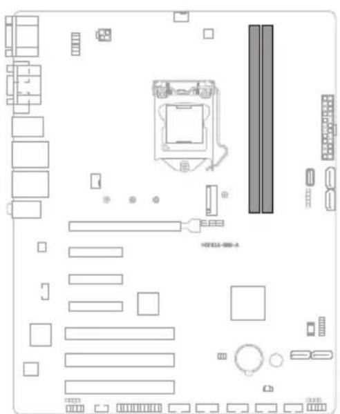

| Channel Sockets |
| Channel A DIMM_A |
| Channel B DIMM_B |
2.4 Jumpers
1. Clear RTC RAM (2-pin CLRTC)
This header allows you to clear the CMOS RTC RAM data of the system setup information such as date, time, and system passwords.

Connector type
HEADER 1x2p, 2.54mm pitch, S/T
To erase the RTC RAM:
- Turn OFF the computer and unplug the power cord.
- Short-circuit pin 1-2 with a metal object or jumper cap for about 5-10 seconds.
- Plug the power cord and turn ON the computer.
- Hold down the
key during the boot process and enter BIOS setup to re-enter data.

CAUTION! DO NOT short-circuit the pins except when clearing the RTC RAM. Short-circuiting or placing a jumper cap will cause system boot failure!

NOTE: If the steps above do not help, remove the onboard button cell battery and short the two pins again to clear the CMOS RTC RAM data. After clearing the CMOS, reinstall the button cell battery.
2. COM Ring/+5V/+12V selection jumper (6-pin COM1/2\_SEL)


| Setting Pins | |
| +12V 1-2 | |
| +5V 3-4 | |
| Ring (Default) 5-6 |
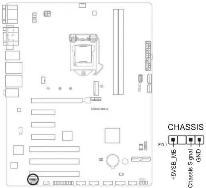
3. Chassis Intrusion header (4-1 pin CHASSIS)
The Chassis Intrusion header is for a chassis-mounted intrusion detection sensor or switch. Connect one end of the chassis intrusion sensor or switch cable to this connector. The chassis intrusion sensor or switch sends a high-level signal to this connector when a chassis component is removed or replaced. The signal is then generated as a chassis intrusion event.
2.5 Internal connectors
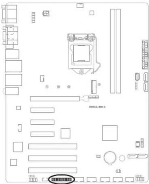
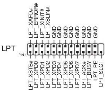
1. LPT header (26-1 pin LPT)
The LPT (Line Printing Terminal) connector supports devices such as a printer. LPT standardizes as IEEE 1284, which is the parallel port interface on IBM PC-compatible computers.
2. General Purpose Input/Output connector (GPIO\_CON)
The General Purpose Input/Output connector is for a general purpose input/output module which allows you to customize the digital signal input/output.


3. USB 2.0 headers (USB7 / USB8 / USB914)
The USB 2.0 headers are for USB 2.0 ports. Connect the USB cable to any of these headers. These USB headers comply with USB 2.0 specification that supports up to 480 Mbps connection speed.
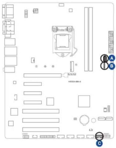
A USB8

B USB7

USB914


CAUTION! Never connect a 1394 cable to the USB connector. Doing so will damage the motherboard.

NOTE: The USB cable is purchased separately.
4. CPU and Chassis Fan headers (4-pin CPU\_FAN, 4-pin CHA\_FAN)
Connect the fan cables to the fan headers on the motherboard, ensuring that the black wire of each cable matches the ground pin of the header.
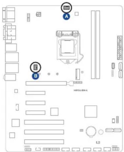

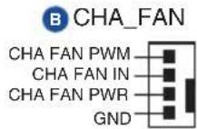

CAUTION! Do not forget to connect the fan cables to the fan connectors. Insufficient air flow inside the system may damage the motherboard components. These are not jumpers! Do not place jumper caps on the fan connectors!
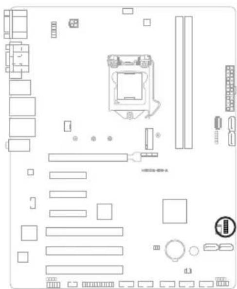
5. TPM header (14-1 pin TPM)
The TPM header supports a Trusted Platform Module (TPM) system, which can securely store keys, digital certificates, passwords, and data. A TPM system also helps enhance network security, protects digital identities, and ensures platform integrity.

6. System Panel header (10-1 pin F\_PANEL)
The System Panel header supports several chassis-mounted functions.

- System power LED (2-pin +PWR\_LED)
This 2-pin connector is for the system power LED. Connect the chassis power LED cable to this connector. The system power LED lights up when you turn on the system power, and blinks when the system is in sleep mode.
• Hard disk drive activity LED (2-pin +HDD\_LED)
This 2-pin connector is for the HDD Activity LED. Connect the HDD Activity LED cable to this connector. The IDE LED lights up or flashes when data is read from or written to the HDD.
• ATX power button/soft-off button (2-pin PWR\_BTN)
This 2-pin connector is for the system power button.
- Reset button (2-pin RESET)
This 2-pin connector is for the chassis-mounted reset button for system reboot without turning off the system power.
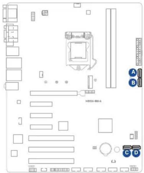
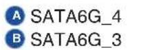
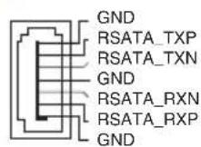
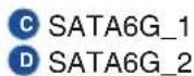
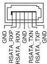
7. SATA 6.0Gb/s port (7-pin SATA6G\_1-4)
The SATA 6.0Gb/s port connects to a Serial ATA 6.0 Gb/s hard disk drive or an optical drive via a Serial ATA 6.0 Gb/s signal cable.
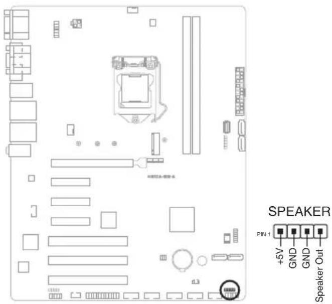
8. Speaker header (4-pin SPEAKER)
The Speaker header is for the chassis-mounted system warning speaker. The speaker allows you to hear system beeps and warnings.
9. M.2 socket 3
This socket allows you to install an M.2 SSD module.


NOTES:
• The M.2 SSD module is purchased separately.
• This socket supports M Key and 2242/2260/2280 storage devices.

IMPORTANT! The torque value for locking the screw/stud is 2 +/-0.2 kgf.cm.
10. COM Debug header
The COM Debug header allows connection to a COM Debug card.
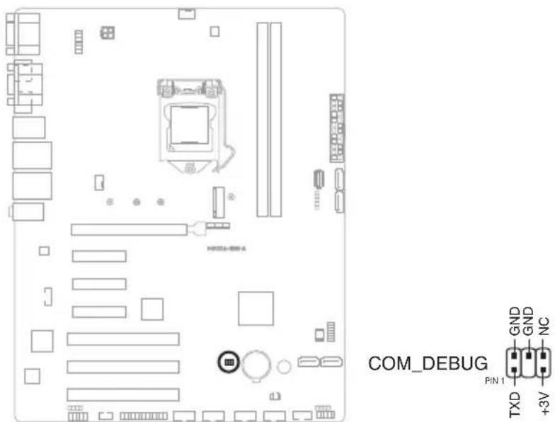

NOTE: The COM Debug card is purchased separately.
11. Keyboard and Mouse Port connector (8-pin KBMS\_CON)
The Keyboard and Mouse Port connector allows you to connect a PS/2 keyboard and mouse.

| Pins Signal Pins Signal | |||
| 1 O_KB_CLK_R 2 O_MS_CLK_R | |||
| 3 O_KB_DATA_R 4 O_MS_DATA_R | |||
| 5 GND 6 GND | |||
| 7 +5V_ZPS2 8 +5V_ZPS2 | |||
12. Serial Port headers (10-1 pin COM3-6)
The Serial Port headers are for serial (COM) ports. Connect the serial port cables to these headers, then install the module to a slot opening at the back of the system chassis.


NOTE: The serial port cables are purchased separately.
13. Front Panel Audio header (10-1 pin AAFP)
The Front Panel Audio header is for a chassis-mounted front panel audio I/O module that supports HD Audio standard. Connect one end of the front panel audio I/O module cable to this header.


IMPORTANT!
- We recommend that you connect a high-definition front panel audio module to this header to avail of the motherboard's high-definition audio capability.
- If you want to connect a high-definition front panel audio module to this connector, set the HD Audio Controller item in the BIOS Setup to [Enabled].
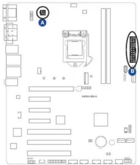
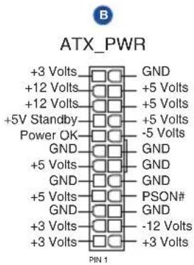
14. ATX Power connectors (24-pin ATX\_PWR, 4-pin ATX12V)
Correctly orient the ATX power supply plugs into these connectors and push down firmly until the connectors completely fit.

2.6 Slots
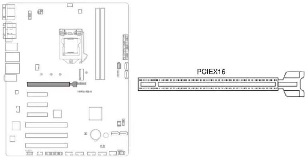
1. PCI Express x16 slot
This slot supports a PCIe x16 graphics card that complies with the PCI Express specification.
2. PCI Express x4 slots
This motherboard supports three PCIe x4 network cards, SCSI cards and other cards that comply with the PCI Express specification.

3. PCI slots
The PCI slots support cards such as LAN cards, SCSI cards, USB cards, and other cards that comply with PCI specification.
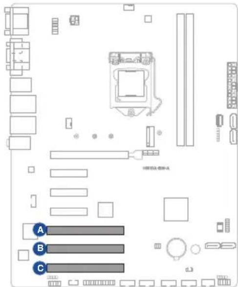
A PCI1
B PCI2
c PCI3

Chapter 3
This chapter provides a detailed guide to navigating and setting up the BIOS.

natural_image
Line drawing of a rectangular electronic device labeled 'ASUS IoT' with a grid-patterned side panel (no additional text or symbols)BIOs setup
3.1 BIOS setup program
Use the BIOS Setup program to update the BIOS or configure its parameters. The BIOS screens include navigation keys and brief online help to guide you in using the BIOS Setup program.
Entering BIOS Setup at startup
To enter BIOS Setup at startup:
Press
Entering BIOS Setup after POST
To enter BIOS Setup after POST:
- Press
+ + simultaneously. - Press the reset button on the system chassis.
- Press the power button to turn the system off then back on. Do this option only if you failed to enter BIOS Setup using the first two options.

CAUTION! Using the power button, reset button, or the keys to reboot a running operating system can cause damage to your data or system. Always shut down the system properly from the operating system.

IMPORTANT:
- Visit the ASUS website at www.asus.com to download the latest BIOS file for this motherboard.
- The default BIOS settings for this motherboard apply to most working conditions and ensures optimal performance. If the system becomes unstable after changing any BIOS settings, load the default settings to regain system stability. Select the option Load Optimized Defaults under the Exit Menu or press hotkey F5.
- The BIOS setup screens shown in this section are for reference purposes only, and may not exactly match what you see on your screen.
3.1.1 BIOS menu screen
Menu bar
The menu bar on top of the screen has the following main items:
| Main | For changing the basic system configuration. |
| Ai Tweaker | For changing the overclocking settings |
| Advanced | For changing the advanced system settings. |
| Monitor | For displaying the system temperature, power status, and changing the fan settings |
| Boot | For changing the system boot configuration. |
| Tool | For configuring options for special functions |
| Exit | For selecting the exit options and loading default settings. |
To select an item on the menu bar, press the right or left arrow key on the keyboard until the desired item is highlighted.
3.2 Main menu
The Main menu provides you an overview of the basic system information, and allows you to set the system date, time, language, and security settings.
3.2.1 Language [English]
Allows you to choose the BIOS language version from the options. Configuration options: [English] [Spanish] [Deutsch] [简体中文] [繁體中文] [日本語] [Русский] [Korean]
3.2.2 System Date [Day MM/DD/YYYY]
Allows you to set the system date.
3.2.3 System Time [HH:MM:SS]
Allows you to set the system time.
3.2.4 Security
The Security menu items allow you to change the system security settings.

NOTES:
- If you have forgotten your BIOS password, erase the CMOS Real Time Clock (RTC) RAM to clear the BIOS password. See section 2.5 Jumpers for information on how to erase the RTC RAM.
- The Administrator or User Password items on top of the screen show the default Not Installed. After you set a password, these items show Installed.
Administrator Password
If you have set an administrator password, we recommend that you enter the administrator password for accessing the system.
To set an administrator password:
- Select the Administrator Password item and press
. - From the Create New Password box, key in a password, then press
. - From the Confirm New Password box, key in your password again to confirm the password, then click OK.
To change an administrator password:
- Select the Administrator Password item and press
. - From the Enter Current Password box, key in the current password, then press
. - From the Create New Password box, key in a new password, then press
. - From the Confirm New Password box, key in your password again to confirm the password, then click OK.
To clear the administrator password, follow the same steps as in changing an administrator password, but click OK when prompted to create/confirm the password. After you clear the password, the Administrator Password item on top of the screen shows Not Installed.
User Password
If you have set a user password, you must enter the user password for accessing the system. The User Password item on top of the screen shows the default Not Installed. After you set a password, this item shows Installed.
To set a user password:
- Select the User Password item and press
. - From the Create New Password box, key in a password, then press
. - From the Confirm New Password box, key in your password again to confirm the password, then click OK.
To change a user password:
- Select the User Password item and press
. - From the Enter Current Password box, key in the current password, then press
. -
From the Create New Password box, key in a new password, then press
. -
From the Confirm New Password box, key in your password again to confirm the password, then click OK.
To clear the user password, follow the same steps as in changing a user password, but click OK when prompted to create/confirm the password. After you clear the password, the User Password item on top of the screen shows Not Installed.
3.3 Ai Tweaker menu
The Ai Tweaker menu items allow you to configure overclocking-related items.

CAUTION! Be cautious when changing the settings of the Ai Tweaker menu items. Incorrect field values can cause the system to malfunction.

NOTE: The configuration options for this section vary depending on the CPU and DIMM model you installed on the motherboard.
3.3.1 CPU Power Enhancement
This item allows you to reset the CPU load-line to the Intel default settings.
Configuration options: [Auto] [Disabled]
3.3.2 CPU Core Ratio
This item allows you to set the CPU core ratio limit per core or synchronize automatically to all cores.
Configuration options: [Auto] [Sync All Cores] [Per Core]

NOTE: When the CPU Core Ratio is set to [Sync All Cores] or [Per Core], the following item appears.
1-Core Ratio Limit
Enter [Auto] to apply the CPU default Turbo Ratio setting or manually assign a 1-Core Limit value that must be higher than or equal to the 2-Core Ratio Limit.

NOTE: When the CPU Core Ratio is set to [Per Core], the following items appears.
2-Core Ratio Limit
Enter [Auto] to apply the CPU default Turbo Ratio setting or manually assign a 2-core ratio limit that must be higher than or equal to the 3-core ratio limit.

CAUTION! If you assign a value for 2-Core Ratio Limit, do not set the 1-Core Ratio Limit to [Auto].
3-Core Ratio Limit
Enter [Auto] to apply the CPU default Turbo Ratio setting or manually assign a 3-core ratio limit that must be higher than or equal to the 4-core ratio limit.

CAUTION! If you assign a value for 3-Core Ratio Limit, do not set the 1-Core Ratio Limit and 2-Core Ratio Limit to [Auto].
4-Core Ratio Limit
Enter [Auto] to apply the CPU default Turbo Ratio setting or manually assign a 4-core ratio limit that must be higher than or equal to the 5-core ratio limit.

CAUTION! If you assign a value for 4-Core Ratio Limit, do not set the 1-Core Ratio Limit, 2-Core Ratio Limit, and 3-Core Ratio Limit to [Auto].
5-Core Ratio Limit
Enter [Auto] to apply the CPU default Turbo Ratio setting or manually assign a 5-core ratio limit that must be higher than or equal to the 6-core ratio limit.

CAUTION! If you assign a value for 5-Core Ratio Limit, do not set the 1-Core Ratio Limit, 2-Core Ratio Limit, 3-Core Ratio Limit and 4-Core Ratio Limit to [Auto].
6-Core Ratio Limit
Enter [Auto] to apply the CPU default Turbo Ratio setting or manually assign a 6-core ratio limit that must be lower than or equal to the 5-core ratio limit.

CAUTION! If you assign a value for 4-Core Ratio Limit, do not set the 1-Core Ratio Limit, 2-Core Ratio Limit, 3-Core Ratio Limit, 4-Core Ratio Limit, and 5-Core Ratio Limit to [Auto].
3.3.3 DRAM Odd Ratio Mode
This item allows you to enable or disable availability of odd DRAM ratios for improved granularity.
Configuration options: [Enabled] [Disabled]
3.3.4 DRAM Frequency
This item allows you to set the memory operating frequency. The configurable options vary with the BCLK (base clock) frequency setting. Select the auto mode to apply the optimized setting.
Configuration options: [Auto] [DDR4-800MHz] - [DDR4-8533MHz]
3.3.5 Power-saving & Performance Mode
Power-saving & Performance Mode lets you configure the power usage to boost or enhance system performance.
[Auto] Automatically adjusts the power usage based on the system load.
[Max Power-Saving Mode] Enables all power-saving settings for maximum energy-saving condition
[Performance Mode] Disables all power-saving settings to achieve a high system performance.
3.3.6 DRAM Timing Control
The sub-items in this menu allow you to set the DRAM timing control features. Use the <+> and <-> keys to adjust the value. To restore the default setting, type [auto] using the keyboard and press the

CAUTION! Changing the values in this menu may cause the system to become unstable! If this happens, revert to the default settings.
Primary Timings
DRAM CAS# Latency
Configuration option: [Auto]
DRAM RAS# to CAS# Delay
Configuration option: [Auto]
DRAM RAS# ACT Time
Configuration options: [Auto]
DRAM Command Rate
Configuration options: [Auto] [1N] [2N] [3N] [N:1]
Secondary Timings
DRAM RAS# to RAS# Delay L
Configuration option: [Auto]
DRAM RAS# to RAS# Delay S
Configuration option: [Auto]
DRAM REF Cycle Time
Configuration option: [Auto]
DRAM Refresh Interval
Configuration option: [Auto]
DRAM WRITE Recovery Time
Configuration option: [Auto]
DRAM READ to PRE Time
Configuration option: [Auto]
DRAM FOUR ACT WIN Time
Configuration option: [Auto]
DRAM WRITE to READ Delay
Configuration option: [Auto]
DRAM WRITE to READ Delay L
Configuration option: [Auto]
DRAM WRITE to READ Delay S
Configuration option: [Auto]
DRAM CKE Minimum Pulse Width
Configuration option: [Auto]
DRAM Write Latency
Configuration option: [Auto]
Skew Control
ODT RTT WR (CHA)
Configuration options: [Auto] [0 DRAM Clock] [80 DRAM Clock] [120 DRAM Clock] [240 DRAM Clock] [255 DRAM Clock]
ODT RTT PARK (CHA)
Configuration options: [Auto] [0 DRAM Clock] [34 DRAM Clock] [40 DRAM Clock] [48 DRAM Clock] [60 DRAM Clock] [80 DRAM Clock] [120 DRAM Clock] [240 DRAM Clock]
ODT RTT NOM (CHA)
Configuration options: [Auto] [0 DRAM Clock] [34 DRAM Clock] [40 DRAM Clock] [48 DRAM Clock] [60 DRAM Clock] [80 DRAM Clock] [120 DRAM Clock] [240 DRAM Clock]
ODT RTT WR (CHB)
Configuration options: [Auto] [0 DRAM Clock] [80 DRAM Clock] [120 DRAM Clock] [240 DRAM Clock] [255 DRAM Clock]
ODT RTT PARK (CHB)
Configuration options: [Auto] [0 DRAM Clock] [34 DRAM Clock] [40 DRAM Clock] [48 DRAM Clock] [60 DRAM Clock] [80 DRAM Clock] [120 DRAM CLOCK] [240 DRAM Clock]
ODT RTT NOM (CHB)
Configuration options: [Auto] [0 DRAM Clock] [34 DRAM Clock] [40 DRAM Clock] [48 DRAM Clock] [60 DRAM Clock] [80 DRAM Clock] [120 DRAM Clock] [240 DRAM Clock]
ODT\_READ\_DURATION
Configuration option: [Auto]
ODT\_READ\_DELAY
Configuration option: [Auto]
ODT\_WRITE\_DURATION
Configuration option: [Auto]
ODT_WRITE_DELAY
Configuration option: [Auto]
Data Rising Slope
Configuration option: [Auto]
Data Rising Slope Offset
Configuration option: [Auto]
Cmd Rising Slope
Configuration option: [Auto]
Cmd Rising Slope Offset
Configuration option: [Auto]
Ctl Rising Slope
Configuration option: [Auto]
Ctl Rising Slope Offset
Configuration option: [Auto]
Clk Rising Slope
Configuration option: [Auto]
Clk Rising Slope Offset
Configuration option: [Auto]
Data Falling Slope
Configuration option: [Auto]
Data Falling Slope Offset
Configuration option: [Auto]
Cmd Falling Slope
Configuration option: [Auto]
Cmd Falling Slope Offset
Configuration option: [Auto]
Ctl Falling Slope
Configuration option: [Auto]
Ctl Falling Slope Offset
Configuration option: [Auto]
Clk Falling Slope
Configuration option: [Auto]
Clk Falling Slope Offset
Configuration option: [Auto]
RTL IOL Control
DRAM RTL INIT Value
Configuration option: [Auto]
DRAM RTL (CHA DIMM0 Rank0)
Configuration option: [Auto]
DRAM RTL (CHA DIMM0 Rank1)
Configuration option: [Auto]
DRAM RTL (CHA DIMM1 Rank0)
Configuration option: [Auto]
DRAM RTL (CHA DIMM1 Rank1)
Configuration option: [Auto]
DRAM RTL (CHB DIMM0 Rank0)
Configuration option: [Auto]
DRAM RTL (CHB DIMM0 Rank1)
Configuration option: [Auto]
DRAM RTL (CHB DIMM1 Rank0)
Configuration option: [Auto]
DRAM RTL (CHB DIMM1 Rank1)
Configuration option: [Auto]
DRAM IOL (CHA DIMM0 Rank0)
Configuration option: [Auto]
DRAM IOL (CHA DIMM0 Rank1)
Configuration option: [Auto]
DRAM IOL (CHA DIMM1 Rank0)
Configuration option: [Auto]
DRAM IOL (CHA DIMM1 Rank1)
Configuration option: [Auto]
DRAM IOL (CHB DIMM0 Rank0)
Configuration option: [Auto]
DRAM IOL (CHB DIMM0 Rank1)
Configuration option: [Auto]
DRAM IOL (CHB DIMM1 Rank0)
Configuration option: [Auto]
DRAM IOL (CHB DIMM1 Rank1)
Configuration option: [Auto]
IO Latency offset
CHA IO_Latency_offset
Configuration option: [Auto]
CHB IO_Latency_offset
Configuration option: [Auto]
IO Latency RFR delay
CHA RFR delay
Configuration option: [Auto]
CHB RFR delay
Configuration option: [Auto]
Memory Training Algorithms
Early Command Training
Configuration options: [Enabled] [Disabled]
SenseAmp Offset Training
Configuration options: [Enabled] [Disabled]
Early ReadMPR Timing Centering 2D
Configuration options: [Enabled] [Disabled]
Read MPR Training
Configuration options: [Enabled] [Disabled]
Receive Enable Training
Configuration options: [Enabled] [Disabled]
Jedec Write Leveling
Configuration options: [Enabled] [Disabled]
Early Write Time Centering 2D
Configuration options: [Enabled] [Disabled]
Early Read Time Centering 2D
Configuration options: [Enabled] [Disabled]
Write Timing Centering 1D
Configuration options: [Enabled] [Disabled]
Write Voltage Centering 1D
Configuration options: [Enabled] [Disabled]
Read Timing Centering 1D
Configuration options: [Enabled] [Disabled]
DIMM ODT Training
Configuration options: [Auto] [Enabled] [Disabled]
Max RTT\_WR
Configuration options: [ODT Off] [120Ohms]
DIMM RON Training
Configuration options: [Auto] [Enabled] [Disabled]
Write Drive Strength/Equalization 2D
Configuration options: [Enabled] [Disabled]
Write Slew Rate Training
Configuration options: [Enabled] [Disabled]
Read ODT Training
Configuration options: [Enabled] [Disabled]
Read Equalization Training
Configuration options: [Enabled] [Disabled]
Read Amplifier Training
Configuration options: [Enabled] [Disabled]
Write Timing Centering 2D
Configuration options: [Enabled] [Disabled]
Read Timing Centering 2D
Configuration options: [Enabled] [Disabled]
Command Voltage Centering
Configuration options: [Enabled] [Disabled]
Write Voltage Centering 2D
Configuration options: [Enabled] [Disabled]
Read Voltage Centering 2D
Configuration options: [Enabled] [Disabled]
Late Command Training
Configuration options: [Auto] [Enabled] [Disabled]
Round Trip Latency
Configuration options: [Auto] [Enabled] [Disabled]
Turn Around Timing Training
Configuration options: [Enabled] [Disabled]
Rank Margin Tool
Configuration options: [Enabled] [Disabled]
Memory Test
Configuration options: [Enabled] [Disabled]
DIMM SPD Alias Test
Configuration options: [Enabled] [Disabled]
Receive Enable Centering 1D
Configuration options: [Enabled] [Disabled]
Retrain Margin Check
Configuration options: [Enabled] [Disabled]
Write Drive Strength Up/Dn independently
Configuration options: [Enabled] [Disabled]
Third Timings
tRDRD\_sg
Configuration option: [Auto]
tRDRD\_dg
Configuration option: [Auto]
tRDWR\_sg
Configuration option: [Auto]
tRDWR\_dg
Configuration option: [Auto]
tWRWR\_sg
Configuration option: [Auto]
tWRWR\_dg
Configuration option: [Auto]
tWRRD\_sg
Configuration option: [Auto]
tWRRD\_dg
Configuration option: [Auto]
tRDRD\_dr
Configuration option: [Auto]
tRDRD\_dd
Configuration option: [Auto]
tRDWR\_dr
Configuration option: [Auto]
tRDWR_dd
Configuration option: [Auto]
tWRWR_dr
Configuration option: [Auto]
tWRWR_dd
Configuration option: [Auto]
tWRRD_dr
Configuration option: [Auto]
tWRRD_dd
Configuration option: [Auto]
TWRPRE
Configuration option: [Auto]
TRDPRE
Configuration option: [Auto]
tREFIX9
Configuration option: [Auto]
OREF_RI
Configuration option: [Auto]
Misc.
MRC Fast Boot
Allows you to enable, disable or automatically set the MRC fast boot.
Configuration options: [Auto] [Enabled] [Disabled]
DRAM CLK Period
Configuration options: [Auto] [1] - [58]
Memory Scrambler
Set this item to enable or disable memory scrambler support.
Configuration options: [Enabled] [Disabled]
Channel A DIMM Control
Allows you to enable or disable the Channel A DIMM slots.
Configuration options: [Enable Both DIMMs] [Disable DIMM0] [Disable
DIMM1] [Disable Both DIMMs]
Channel B DIMM Control
Allows you to enable or disable the Channel B DIMM slots.
Configuration options: [Enable Both DIMMs] [Disable DIMM0] [Disable
DIMM1] [Disable Both DIMMs]
MCH Full Check
Enable this item to enhance the stability of your system. Disable this item to enhance the DRAM overclocking capability.
Configuration options: [Auto] [Enabled] [Disabled]
Training Profile
Configuration options: [Auto] [Standard Profile] [ASUS User Profile]
DLLBwEn
Configuration option: [Auto]
SPD Write Disable
Configuration options: [TRUE] [FALSE]
3.3.7 DIGI+ VRM
CPU Load-line Calibration
Load-line is defined by Intel® specification and affects CPU power voltage. The CPU working voltage decreases proportionally to CPU loading. Higher load-line calibration could get higher voltage and good overclocking performance, but increases the CPU and VRM thermal conditions. Select from levels 1 to 7 to adjust the load-line slope.
Configuration options [Auto] [Default] [Level 1] - [Level 7]

NOTE: The actual performance boost may vary depending on your CPU specification.

CAUTION! DO NOT remove the thermal module. The thermal conditions should be monitored.
CPU Power Phase Control
This item allows you to set the power phase control of the CPU.
[Auto] Automatically set the phase control mode.
[Standard] The phase control will be based on the CPU command.
[Extreme] Set to the full phase mode.

CAUTION! DO NOT remove the thermal module when setting this item to [Extreme]. The thermal conditions should be monitored.
CPU VRM Thermal Control
This item allows you to adjust the temperature limit of the CPU VRM.
Configuration options: [Atuo] [Enabled] [Disabled]
CPU Graphics Load-Line Calibration
Load-line is defined by Intel VRM specification and affects the GT power voltage. The GT working voltage will decrease proportionally depending on the GT loading. Higher levels of the load-line calibration can get a higher voltage and a better overclocking performance but increases the GT and VRM thermal. Select from level 1 to 7 to adjust the GT power voltage from 0% to 100%. Configuration options: [Auto] [Level 1] [Level 2] [Level 3] [Level 4] [Level 5] [Level 6] [Level 7]

NOTE: The boosted performance may vary depending on the GT specification. Do not remove the thermal module.
3.3.8 Internal CPU Power Management
The subitems in this menu allow you to set the CPU ratio and features.
Intel(R) SpeedStep(tm)
Allows the operating system to dynamically adjust the processor voltage and cores frequency to decrease the average power consumption and decrease average heat production. Configuration options: [Auto] [Enabled] [Disabled]
Turbo Mode
Allows you to enable your processor cores to run faster than the base operating frequency when it is below power, current and specification limit. Configuration options: [Disabled] [Enabled]
Turbo Mode Parameters

NOTE: The following items appear only when you set the Turbo Mode to [Enabled].
Long Duration Package Power Limit
As know as the power limit 1 in Watts. The default value will be the TDP (thermal design power). The turbo ratio can be maintained for a duration to exceed the TDP for the maximum system performance.
Configuration options: [Auto] [1] - [4095]
Package Power Time Window
As know as the power limit 1 in seconds. The value indicates the maintained duration for the turbo ratio to exceed TDP (thermal design power).
Configuration options: [Auto] [1] - [127]
Short Duration Package Power Limit
Also know as the power limit 2 in Watts. It is the second power limit to provide a rapid protection when the package power exceed power limit 1. The default setting is 1.25 times the power limit 1. According to Intel, the platform must be capable of supporting the duration for up to 10 msec when the turbo ratio exceeds the power limit 2.
Configuration options: [Auto]
IA AC Load Line
This item allows you to set the AC loadline defined in 1/100 mOhms.
Configuration options: [Auto] [0.00] - [62.49]
IA DC Load Line
This item allows you to set the DC loadline defined in 1/100 mOhms.
Configuration options: [Auto] [0.00] - [62.49]
3.3.9 CPU Core/Cache Current Limit Max.
This item allows you to configure a higher current limit to prevent a frequency or power throttling when overclocking.
Configuration options: [Auto] [0.00] - [255.50]
3.3.10 CPU Graphics Current Limit
Allows you to set a higher current limit to prevent a frequency or power throttling when overclocking.
3.3.11 Min. CPU Cache Ratio
This item allows you to set the minimum possible CPU cache ratio.
Configuration option: [Auto]
3.3.12 Max. CPU Cache Ratio
This item allows you to set the maximum possible CPU cache ratio.
Configuration option: [Auto]
3.3.13 Max. CPU Graphics Ratio
This item allows you to set the maximum possible CPU graphics ratio.
Configuration option: [Auto]
3.3.14 DRAM Voltage
This item allows you to configure the voltage for the DRAM.
Configuration options: [Auto] [1.20V] [1.25V] [1.35V] [1.40V]
3.3.15 DRAM REF Voltage Control
DRAM CTRL REF Voltage
Configures the DRAM reference voltage on the control lines. The reference voltage will be the DRAM voltage times the configured value.
Configuration options: [Auto] [0.39500X] - [0.63000X]
DRAM DATA REF Voltage on CHB
Configures the DRAM Data REF Voltage.
Configuration option: [Auto]
DRAM DATA REF Voltage on CHA DIMM0 Rank0 BL0-7
Configures the DRAM Data REF Voltage.
Configuration option: [Auto]
DRAM DATA REF Voltage on CHA DIMM0 Rank1 BL0-7
Configures the DRAM Data REF Voltage.
Configuration option: [Auto]
DRAM DATA REF Voltage on CHB DIMM0 Rank0 BL0-7
Configures the DRAM Data REF Voltage.
Configuration option: [Auto]
DRAM DATA REF Voltage on CHB DIMM0 Rank1 BL0-7
Configures the DRAM Data REF Voltage.
Configuration option: [Auto]
3.4 Advanced menu
The Advanced menu items allow you to change the settings for the CPU and other system devices.

CAUTION! Be cautious when changing the settings of the Advanced menu items. Incorrect field values can cause the system to malfunction.
3.4.1 Platform Misc Configuration
The items in this menu allow you to configure the platform-related features.
PCI Express Native Power Management [Disabled]
This item allows you to enhance the power saving feature of PCI Express and perform ASPM operations in the operating system. Configuration options: [Disabled] [Enabled]
![ASUS EBS-A710 - PCI Express Native Power Management [Disabled] - 1](/content/2026/05/986314/images/cbd49f6b61e0dd50144b8f865b88b33b4784fbf2d6ad597393a6480c143e9c8b.jpg)
IMPORTANT: The following item appears only when you set the PCI Express Native Power Management to [Enabled].
Native ASPM [Disabled]
[Enabled]
Windows® Vista OS controls the ASPM (active state power management) support for devices.
[Disabled] BIOS controls the ASPM support for the device.
[Auto] Automatic configuration.
PCH - PCI Express options
PCH DMI ASPM [Disabled]
This item allows you to control the Active State Power Management on both NB (NorthBridge) side and SB (SouthBridge) side of the DMI Link.
Configuration options: [Disabled] [L0s] [L1] [L0sL1] [Auto]
ASPM [Disabled]
This item allows you to select the ASPM state for energy-saving conditions.
Configuration options: [Disabled] [L0s] [L1] [L0sL1] [Auto]
L1 Substates [Disabled]
This item allows you to select the PCI Express L1 Substates settings. Configuration options: [Disabled] [L1.1] [L1.1 & L1.2]
PCI Express Clock Gating [Enabled]
This item allows you to enable or disable PCI Express Clock Gating for each port. Configuration options: [Disabled] [Enabled]
SA - PCI Express options
DMI Link ASPM Control [Disabled]
This item allows you to control the Active State Power Management on both CPU and PCH (platform controller hub) Both DMI link ASPM control items of the CPU and PCH sides must be enabled for the ASPM to take effect. Configuration options: [Disabled] [L0s] [L1] [L0sL1]
PEG-ASPM [Disabled]
This item allows you to select the ASPM state for energy-saving conditions, or use the ASUS optimized energy saving profile. Configuration options: [Disabled] [Auto] [ASPM L0s] [ASPM L1] [ASPM L0sL1]
3.4.2 CPU Configuration
The items in this menu show CPU-related information the BIOS automatically detects.

NOTE: The items shown in the submenu may be different depending on the type of CPU installed.
Software Guard Extensions [Software Controlled]
This item enables/disables the Software Guard Extensions (SGX). Configuration options: [Disabled] [Software Controlled]
Hardware Prefetcher [Enabled]
This item allows you to turn on/off the MLC streamer prefetcher. Configuration options: [Disabled] [Enabled]
Adjacent Cache Line Prefetcher [Enabled]
This item allows you to turn on/off prefetching adjacent cache lines. Configuration options: [Disabled] [Enabled]
Intel Virtualization Technology [Disabled]
When set to [Enabled], a VMM can utilize the additional hardware capabilities provided by Vanderpool Technology. Configuration options: [Disabled] [Enabled]
Active Processor Cores [All]
This item allows you to select the number of CPU cores to activate in each processor package. Configuration options: [All] [1] [2] [3] [4] [5]
![ASUS EBS-A710 - Active Processor Cores [All] - 1](/content/2026/05/986314/images/0f0f04cc8f818046a689b957096350dc92b8d16e2a11bdfebdbf070fa6b7ab9a.jpg)
NOTE: For some CPU types, only [All] and [1] appear.
Hyper-threading [Enabled]
The Intel Hyper-Threading Technology allows a hyper-threading processor to appear as two logical processors to the operating system, allowing the operating system to schedule two threads or processes simultaneously.
[Enabled] Two threads per activated core are enabled.
[Disabled] Only one thread per activated core is enabled.
![ASUS EBS-A710 - Hyper-threading [Enabled] - 1](/content/2026/05/986314/images/eb5dc0d06873c51d729bca20ef21314ad0f56324194d45d1a5829ff6b47d4a47.jpg)
NOTE: Hyper-Threading appears only when using a CPU supporting Hyper-Threading Technology.
Thermal Monitor [Enabled]
The item allows you to enable or disable Thermal Monitor.
Configuration options: [Disabled] [Enabled]
CPU Power Management Control
This item allows you to manage and configure the CPU's power.
Intel(R) SpeedStep(tm) [Auto]
This item allows your system to support more than two frequency ranges. Configuration options: [Auto] [Disabled] [Enabled]
Intel(R) Speed Shift Technology [Auto]
This item allows you to enable or disable Intel(R) Speed Shift Technology support. When enabled, CPPC v2 interface allows hardware controlled P-states.Configuration options: [Auto] [Disabled] [Enabled]
Turbo Mode [Enabled]
This item allows you to automatically set the CPU cores to run faster than the base operating frequency when it is below the operating power, current and temperature specification limit. Configuration options: [Enabled] [Disabled]
![ASUS EBS-A710 - Turbo Mode [Enabled] - 1](/content/2026/05/986314/images/ebe3b69939457772187abae76948ddbb1730704dff9c654588f0b8ba0c7f5bde.jpg)
NOTE: Turbo Mode is only available on selected CPU models only.
CPU C-states [Auto]
This item allows you to set the power saving of the CPU states. Configuration options: [Auto] [Disabled] [Enabled]
![ASUS EBS-A710 - CPU C-states [Auto] - 1](/content/2026/05/986314/images/10ad0a1e4f52d9ed719689ff85d459752745cff6ed0d980e66b0e3ac25ad7b5c.jpg)
NOTE: The following items appear only when you set the CPU C-States to [Enabled].
Enhanced C-states [Enabled]
[Enabled] Enables enhanced C1 state.
[Disabled] Disables enhanced C1 state.
CPU C3 Report [Enabled]
Allows you to disable or enable the CPU C3 report to OS. Configuration options: [Enabled] [Disabled]
CPU C6 Report [Disabled]
Allows you to disable or enable the CPU C6 report to OS. Configuration options: [Enabled] [Disabled]
CPU C7 Report [Disabled]
Allows you to disable or enable the CPU C7 report to OS. Configuration options: [Disabled] [CPU C7] [CPU C7s]
CPU C8 Report [Disabled]
Allows you to disable or enable the CPU C8 report to OS. Configuration options: [Enabled] [Disabled]
CPU C9 Report [Disabled]
Allows you to disable or enable the CPU C9 report to OS. Configuration options: [Enabled] [Disabled]
CPU C10 Report [Disabled]
Allows you to disable or enable the CPU C10 report to OS. Configuration options: [Enabled] [Disabled]
Package C State Limit [Auto]
Allows you to disable or enable the whole C-State package support. Configuration options: [C0/C1] [C2] [C3] [C6] [C7] [C7s] [C8] [C9] [C10] [Auto] [CPU Default] [Auto]
CFG Lock [Disabled]
This item allows you to enable or disable the CFG lock. Configuration options: [Disabled] [Enabled]
3.4.3 System Agent (SA) Configuration
VT-d [Disabled]
Allows you to enable or disable VT-d function on MCH. Configuration options: [Enabled] [Disabled]
Above 4G Decoding [Disabled]
Allows you to enable or disable the 4G decoding for 64-bit devices when the system supports the 64-bit PCI decoding. Configuration options: [Enabled] [Disabled]
Memory Configuration
Memory Remap [Enabled]
Allows you to enable or disable remapping the memory above 4GB. Configuration options: [Disabled] [Enabled]
Graphics Configuration
Allows you to select a primary display from iGPU, and PCIe graphical devices.
Primary Display [Auto]
Allows you to select which of the iGPU/PCIE Graphics device should be the Primary Display. Configuration options: [Auto] [CPU Graphics] [PCIE/PCI] [PEG]
iGPU Multi-Monitor [Disabled]
Allows you to enable the iGPU Multi-Monitor. Set this item to [Enabled] to empower both integrated and discrete graphics. The iGPU shared system memory size will be fixed at 64MB. Configuration options: [Disabled] [Enabled]
DVMT Pre-Allocated [64M]
Allows you to select DVMT 5.0 Pre_Allocated (Fixed) Graphics Memory size used by the Internal Graphics Device. Configuration options: [32M] [64M] [96M] \~ [1024M]
RC6(Render Standby) [Auto]
Allows you to enable or disable render standby support. Configuration options: [Disabled] [Auto]
PEG Port Configuration
Allows you to configure the PEG Port settings.
PCIEX16\_1 Link Speed [Auto]
Allows you to configure the PCIEX16_1 speed. Configuration options: [Auto] [Gen1] [Gen2] [Gen3]
3.4.4 PCH Configuration
PCI Express Configuration
PCIe Speed [Auto]
Allows you to configure the PCIe speed. Configuration options: [Auto] [Gen1] [Gen2]
IOAPIC 24-119 Entries [Enabled]
Sets to whether allow IOAPIC 24-119 Entries to expand to PIRQI-PIRQX.
Configuration options: [Disabled] [Enabled]
System Time and Alarm Source [ACPI Time and Alarm Device]
Allows you to select source of system time and alarm functions.
Configuration options: [ACPI Time and Alarm Device] [Legacy RTC]
3.4.5 PCH Storage Configuration
While entering Setup, the BIOS automatically detects the presence of SATA devices. The SATA Port items show Empty if no SATA device is installed to the corresponding SATA port.
SATA Controller(s) [Enabled]
Enables or disables onboard the SATA device. Configuration options: [Disabled] [Enabled]
![ASUS EBS-A710 - SATA Controller(s) [Enabled] - 1](/content/2026/05/986314/images/95ec272f30a33f7c145a24bf75a5a580111828545c60dfb84edcee28563f595d.jpg)
NOTE: The following items appear only when you set SATA Controller(s) to [Enabled].
SATA Mode Selection [AHCI]
Determines how SATA controller(s) operate. This PCH SKU does not support RST feature.
Configuration options: [AHCI]
Aggressive LPM Support [Disabled]
This item is designed for LPM (link power management) support with a better energy saving conditions. When disabled, the hot plug function of SATA ports are disabled. Configuration options: [Disabled] [Enabled]
Smart Self Test [Enabled]
This item allows you to enable or disable the SMART Self Test on all HDDs during POST. Configuration options: [Disabled] [Enabled]
SATA6G\_1\~4(Gray) [Enabled]
Allow you to enable/disable the SATA6G_1\~4 port. Configuration options: [Disabled] [Enabled]
SATA6G\_1\~4 Hot Plug [Disabled]
These items allow you to enable/disable SATA Hot Plug Support. Configuration options: [Disabled] [Enabled]
3.4.6 PCH-FW Configuration
TPM Device Selection [Discrete TPM]
This item allows you to select the TPM device. Configuration options: [Discrete TPM] [Firmware TPM]
3.4.7 Onboard Devices Configuration
HD Audio Controller [Enabled]
[Enabled] Enables the HD Audio Device.
[Disabled] Disables the HD Audio Device.
![ASUS EBS-A710 - HD Audio Controller [Enabled] - 1](/content/2026/05/986314/images/8ee679355af59a140cc522c3863fd5e9ca5b0866eea119e761d9079750e7acd9.jpg)
NOTE: The following items appear only when you set the HD Audio Controller item to [Enabled].
Intel LAN Controller [Enabled]
[Enabled] Enables the Intel LAN controller.
[Disabled] Disables the controller.
![ASUS EBS-A710 - Intel LAN Controller [Enabled] - 1](/content/2026/05/986314/images/01ae7370c6689d4c0555e4d39d1f58f2e5f0af9b901e6a104a83600e47856e0f.jpg)
NOTE: The following items appear only when you set the Intel LAN Controller item to [Enabled].
Intel PXE OPROM [Disabled]
This item allows you to enable or disable the PXE Option ROM of the Intel LAN controller.
Configuration options: [Disabled] [Enabled]
Realtek LAN Controller [Enabled]
[Enabled] Enables the Realtek LAN controller.
[Disabled] Disables the controller.
![ASUS EBS-A710 - Realtek LAN Controller [Enabled] - 1](/content/2026/05/986314/images/4770c1cbb2d538817e75e05a578ba42f73b3e5f9d734043d0def3802f2cc4687.jpg)
NOTE: The following items appear only when you set the Realtek LAN Controller item to [Enabled].
Realtek PXE OPROM [Disabled]
This item allows you to enable or disable the PXE Option ROM of the Realtek LAN controller.
Configuration options: [Disabled] [Enabled]
USB power delivery in Soft Off state (S5) [Disabled]
Allows you to disable or enable USB power when your PC is in the S5 state.
Configuration options: [Disabled] [Enabled]
PCIEX4\_3 Configuration
Configuration options: [Auto] [1x4 Mode] [1x2, 2x1 Mode]
Serial Port 1 Configuration
The sub-items in this menu allow you to set the serial port configuration.
Serial Port [Enabled]
Allows you to enable or disable the serial port (COM). Configuration options: [Disabled] [Enabled]
COM1 Control [RS232]
Allows you to select COM1 mode. Configuration options: [RS422] [RS232] [RS485]
Serial Port 2 Configuration
The sub-items in this menu allow you to set the serial port configuration.
Serial Port [Enabled]
Allows you to enable or disable the serial port (COM). Configuration options: [Disabled] [Enabled]
COM2 Control [RS232]
Allows you to select COM2 mode. Configuration options: [RS422] [RS232] [RS485]
Serial Port 3 Configuration
The sub-items in this menu allow you to set the serial port configuration.
Serial Port [Enabled]
Allows you to enable or disable the serial port (COM). Configuration options: [Disabled] [Enabled]
Serial Port 4 Configuration
The sub-items in this menu allow you to set the serial port configuration.
Serial Port [Enabled]
Allows you to enable or disable the serial port (COM). Configuration options: [Disabled] [Enabled]
Serial Port 5 Configuration
The sub-items in this menu allow you to set the serial port configuration.
Serial Port [Enabled]
Allows you to enable or disable the serial port (COM). Configuration options: [Disabled] [Enabled]
Serial Port 6 Configuration
The sub-items in this menu allow you to set the serial port configuration.
Serial Port [Enabled]
Allows you to enable or disable the serial port (COM). Configuration options: [Disabled] [Enabled]
Parallel Port Configuration
Allows you to set parameters of Parallel Port.
Parallel Port [Enabled]
Allows you to enable or disable the parallel port (LPT/LPTE).
Configuration options: [Disabled] [Enabled]
![ASUS EBS-A710 - Parallel Port [Enabled] - 1](/content/2026/05/986314/images/34f8120e72b52fc6e9431f224f61cd95493be1dbaad32348da57217f296887aa.jpg)
NOTE: The following item appears only when you set Parallel Port to [Enabled].
Change Settings [Auto]
Allows you to choose the setting for Super IO device.
Configuration options: [Auto] [IO=378h; IRQ=5] [IO=378h;
IRQ=5,6,7,9,10,11,12] [IO=278h; IRQ=5,6,7,9,10,11,12] [IO=3BCh;
IRQ=5,6,7,9,10,11,12]
Device Mode [STD Printer Mode]
Allows you to change the Printer Port mode.
Configuration options: [STD Printer Mode] [SPP Mode] [EPP-1.9 and SPP Mode] [EPP-1.7 and SPP Mode] [ECP Mode] [ECP and EPP 1.9 Mode] [ECP and EPP 1.7 Mode]
3.4.8 APM Configuration
ErP Ready [Disabled]
Allows BIOS to switch off some power at S5 to get the system ready for ErP requirement. When set to [Enabled], all other PME options will be switched off. Configuration options: [Enable(S4+S5)] [Enable(S5)] [Disabled]
CEC Ready [Disabled]
Enable this item to allow your system to comply with CEC (California Energy Commission) regulations to save some power at S0 state. Configuration options: [Enable] [Disabled]
Restore AC Power Loss [Power Off]
Allows you to select AC power state when power is re-applied after a power failure. Configuration options: [S5 State] [S0 State] [Last State]
Power On By PCI-E/PCI [Disabled]
This item allows you to enable or disable the Wake-on-LAN function of the onboard LAN controller or other installed PCIe LAN cards. Configuration options: [Disabled] [Enabled]
Power On By Ring [Disabled]
[Disabled] Disables the Ring devices to generate a wake event. [Enabled] Enables the Ring devices to generate a wake event.
Power On By RTC [Disabled]
This item allows you to enable or disable the RTC (Real-Time Clock) to generate a wake event and configure the RTC alarm date. When enabled, you can set the days, hours, minutes, or seconds to schedule an RTC alarm date. Configuration options: [Disabled] [Enabled]
3.4.9 Serial Console Redirection
COM1(\~6)
Console Redirection
Allows you enable or disable the console redirection feature.
Configuration options: [Enabled] [Disabled]

NOTE: The following item is accessible when you set Console Redirection to [Enabled].
Console Redirection Settings
The settings specify how the host computer and the remote computer (which the user is using) will exchange data. Both computers should have the same or compatible settings.
Terminal Type
Configuration options: [VT100] [VT100+] [VT-UTF8] [ANSI]
[VT100] ASCII char set.
[VT100+] Extends VT100 to support color, function keys, etc.
[VT-UTF8] Uses UTF8 encoding to map Unicode chars onto 1 or more bytes.
[ANSI] Extended ASCII char set.
Bits per second
Allows you to select serial port transmission speed. The speed must be matched on the other side. Long or noisy lines may require lower speeds. Configuration options: [9600] [19200] [38400] [57600] [115200]
Data Bits
Configuration options: [7] [8]
Parity
A parity bit can be sent with the data bits to detect some transmission errors. Configuration options: [None] [Even] [Odd] [Mark] [Space]
[None] Disables parity check.
[Even] Parity bit is 0 if the num of 1's in the data bits is even.
[Odd] Parity bit is 0 if the num of 1's in the data bits is odd.
[Mark] Parity bit is always 1.
[Space] Parity bit is always 0.

NOTE: Mark and Space Parity do not allow for error detection.
Stop Bits
Stop bits indicate the end of a serial data packet. The standard setting is 1 stop bit. Communication with slow devices may require more than 1 stop bit. Configuration options: [1] [2]
Flow Control
Flow control can prevent data loss from buffer overflow. When sending data, if the receiving buffers are full, a “stop” signal can be sent to stop the data flow. Once the buffers are empty, a “start” signal can be sent to re-start the flow. Hardware flow control uses two wires to send start/stop signals.
Configuration options: [None] [Hardware RTS/CTS]
VT-UTF8 Combo Key Support
Allows you to enable or disable VT-UTF8 Combination Key Support for ANSI/VT100 terminals. Configuration options: [Disabled] [Enabled]
Recorder Mode
With this mode enabled only text will be sent. This is to capture Terminal data. Configuration options: [Disabled] [Enabled]
Resolution 100x31
Allows you to enable or disable extended terminal resolution. Configuration options: [Disabled] [Enabled]
Putty KeyPad
Allows you to select FunctionKey and KeyPad on Putty. Configuration options: [VT100] [LINUX] [XTERMR6] [SCO] [ESCN] [VT400]
Serial Port for Out-of-Band Management / Windows Emergency Management Services (EMS)
Console Redirection
Allows you enable or disable the console redirection feature. Configuration options: [Enabled] [Disabled]

NOTE: The following item is accessible when you set Console Redirection to [Enabled].
Out-of-Band Mgmt Port
Configuration options: [COM1] [COM2] [COM3] [COM4] [COM5] [COM6]
Terminal Type
Configuration options: [VT100] [VT100+] [VT-UTF8] [ANSI]
[VT100] ASCII char set.
[VT100+] Extends VT100 to support color, function keys, etc.
[VT-UTF8] Uses UTF8 encoding to map Unicode chars onto 1 or more bytes.
[ANSI] Extended ASCII char set.
Bits per second
Allows you to select serial port transmission speed. The speed must be matched on the other side. Long or noisy lines may require lower speeds. Configuration options: [9600] [19200] [57600] [115200]
Flow Control
Flow control can prevent data loss from buffer overflow. When sending data, if the receiving buffers are full, a “stop” signal can be sent to stop the data flow. Once the buffers are empty, a “start” signal can be sent to re-start the flow. Hardware flow control uses two wires to send start/stop signals.
Configuration options: [None] [Hardware RTS/CTS] [Software Xon/Xoff]
3.4.10 PCI Subsystem Settings
SR-IOV Support [Disabled]
Allows you to enable or disable Single Root IO Virtualization Support.
Configuration options: [Enable] [Disabled]
3.4.11 USB Configuration

NOTE: The USB Devices item lists auto-detected values. If no USB device is detected, the item shows None.
Legacy USB Support [Enabled]
[Enabled] Enables the support for USB devices on legacy operating systems (OS).
[Disabled] USB devices are only available when running BIOS Setup.
[Auto] Allows the system to detect the presence of USB devices at startup. If detected, the USB controller legacy mode is enabled. If no USB device is detected, the legacy USB support is disabled.
XHCI Hand-off [Disabled]
This item functions as a workaround for OSes without XHCI hand-off support. The XHCI ownership change should be claimed by XHCI driver.
Configuration options: [Enabled] [Disabled]
USB Single Port Control
This item allows you to enable or disable the individual USB ports.

NOTE: Refer to the manual for the location of the USB ports.
3.4.12 Network Stack Configuration
Network Stack [Disabled]
This item allows user to disable or enable the UEFI network stack. Configuration options: [Disabled] [Enabled]
![ASUS EBS-A710 - Network Stack [Disabled] - 1](/content/2026/05/986314/images/0b5bbe4d2851122fec41d11c3cf5380135e0b817e3a24556c61d9037ff2706be.jpg)
NOTE: The following two items appear only when you set the previous item to [Enabled].
Ipv4 PXE Support [Enabled]
This item allows user to disable or enable the lpv4 PXE Boot support.
Configuration options: [Disabled] [Enabled]
Ipv6 PXE Support [Enabled]
This item allows user to disable or enable the lpv6 PXE Boot support.
Configuration options: [Disabled] [Enabled]
3.4.13 HDD Secure Erase
This menu displays the HDDs that support Secure Erase function.
3.4.14 HDD/SSD SMART Information
This menu displays the SMART information of the connected devices.
3.5 Monitor menu
The Monitor menu displays the system temperature/power status, and allows you to change the fan settings.
CPU / MotherBoard Temperature [xxx°C/xxx°F]
The onboard hardware monitor automatically detects and displays the CPU/ motherboard temperatures. Select Ignore if you do not wish to display the detected temperature.
CPU / Chassis Fan Speed [xxxx RPM] or [Ignore] / [N/A]
The onboard hardware monitor automatically detects and displays the CPU / chassis fan speeds in rotations per minute (RPM). If the fan is not connected to the motherboard, the field shows N/A. Select Ignore if you do not wish to display the detected speed.
CPU Core Voltage, 3.3V Voltage, 5V Voltage, 12V Voltage
The onboard hardware monitor automatically detects the voltage output through the onboard voltage regulators. Select Ignore if you do not want to detect this item.
Q-Fan Configuration
Q-Fan Tuning
Click [OK] button to detect the lowest speed and configure the minimum duty circle for each fan. Do not shut down or reset your system during the tuning progress.
Configuration options: [Ok] [Cancel]
CPU Q-Fan Control [PWM Mode]
[Disabled] Disables the CPU Q-Fan control feature.
[PWM Mode] Enable the CPU Q-Fan control in PWM mode for 4-pin CPU fan.
![ASUS EBS-A710 - CPU Q-Fan Control [PWM Mode] - 1](/content/2026/05/986314/images/bac842391b4930ea39a9fa294e9203f7a6f13cd7e09b79fe78a00f9c02310ec5.jpg)
NOTE: The following items appear only when you set CPU Q-Fan Control to [PWM Mode].
CPU Fan Step Up [0 sec]
This item allows you to set the value of the CPU fan step up.
Configuration options: [0 sec] [2.1 sec] [2.8 sec] [3.6 sec] [4.2 sec] [5.0 sec] [6.3 sec] [8.5 sec] [12 sec] [25 sec]
CPU Fan Step Down [0 sec]
This item allows you to set the value of the CPU fan step down.
Configuration options: [0 sec] [2.1 sec] [2.8 sec] [3.6 sec] [4.2 sec] [5.0 sec] [6.3 sec] [8.5 sec] [12 sec] [25 sec]
CPU Fan Speed Low Limit [200 RPM]
This item appears only when you enable the CPU Q-Fan Control feature and allows you to disable or set the CPU fan warning speed. Configuration options: [Ignore] [200RPM] [300 RPM] [400 RPM] [500 RPM] [600RPM]
CPU Fan Profile [Standard]
This item appears only when you enable the CPU Q-Fan Control feature and allows you to set the appropriate performance level of the CPU fan.
[Standard] Sets to [Standard] to make the CPU fan automatically adjust depending on the CPU temperature.
[Silent] Sets to [Silent] to minimize the fan speed for quiet CPU fan operation.
[Turbo] Sets to [Turbo] to achieve maximum CPU fan speed.
[Manual] Sets to [Manual] to assign detailed fan speed control parameters.
![ASUS EBS-A710 - CPU Fan Profile [Standard] - 1](/content/2026/05/986314/images/09d26fffc41f55862a162772d3f14e6e7e3b908367f413de09f6836f89c6e1f2.jpg)
NOTE: The following four items appear only when you set CPU Fan Profile to [Manual].
CPU Upper Temperature [70]
Use the <+> and <-> keys to adjust the upper limit of the CPU temperature.
CPU Fan Max. Duty Cycle(%) [100]
Use the <+> and <-> keys to adjust the maximum CPU fan duty cycle. The values range from 20% to 100%. When the CPU temperature reaches the upper limit, the CPU fan will operate at the maximum duty cycle.
CPU Middle Temperature [25]
Use the <+> or <-> keys to set the value for CPU Middle Temperature. The range of the values depends on the CPU installed.
CPU Fan Middle Duty Cycle(%) [20]
Use the <+> or <-> keys to adjust the CPU fan middle duty cycle. When the CPU temperature reaches the middle value, the CPU fan operates at the middle duty cycle.
CPU Lower Temperature [20]
Displays the lower limit of the CPU temperature.
CPU Fan Min. Duty Cycle(%) [20]
Use the <+> and <-> keys to adjust the minimum CPU fan duty cycle. When the CPU temperature is under the lower limit, the CPU fan will operate at the minimum duty cycle.
Chassis Fan(s) Configuration
Chassis Fan Q-Fan Control [PWM mode]
[PWM mode] Enables the chassis Q-Fan control in PWM mode for 4-pin chassis fan.
[DC mode] Enables the chassis Q-Fan control in DC mode for 3-pin chassis fan.
[Disabled] Disables the chassis Q-Fan control feature.
![ASUS EBS-A710 - Chassis Fan Q-Fan Control [PWM mode] - 1](/content/2026/05/986314/images/36a009d83d3c1c1eea7ad150a43950c6482a8b371c40105c0ca41839d8abd800.jpg)
NOTE: The following items appear only when you set the Chassis Fan Q-Fan Control to [PWM Mode] or [DC Mode].
Chassis Fan Q-Fan Source [CPU]
This item controls the assigned fan according to the selected temperature source.
Configuration options: [CPU] [MotherBoard]
Chassis Fan Step Up [0 sec]
This item allows you to set the value of the Chassis fan step up.
Configuration options: [0 sec] [12 sec] [25 sec] [51 sec] [76 sec] [102 sec] [127 sec] [153 sec] [178 sec] [204 sec]
Chassis Fan Step Down [0 sec]
This item allows you to set the value of the Chassis fan step down.
Configuration options: [0 sec] [12 sec] [25 sec] [51 sec] [76 sec] [102 sec] [127 sec] [153 sec] [178 sec] [204 sec]
Chassis Fan Speed Low Limit [200 RPM]
This item appears only when you enable the Chassis Q-Fan Control feature and allows you to disable or set the chassis fan warning speed. Configuration options: [Ignore] [200RPM] [300 RPM] [400 RPM] [500 RPM] [600 RPM]
Chassis Fan Profile [Standard]
This item appears only when you enable the Chassis Q-Fan Control feature and allows you to set the appropriate performance level of the chassis fan.
[Standard] Sets to [Standard] to make the chassis fan automatically adjust depending on the chassis temperature.
[Silent] Sets to [Silent] to minimize the fan speed for quiet chassis fan operation.
[Turbo] Sets to [Turbo] to achieve maximum chassis fan speed.
[Manual] Sets to [Manual] to assign detailed fan speed control parameters.
![ASUS EBS-A710 - Chassis Fan Profile [Standard] - 1](/content/2026/05/986314/images/b4341135d5d543ce343642721fe02fc825113b87e76c6dffe5237d5547b84298.jpg)
NOTE: The following four items appear only when you set Chassis Fan Q-Fan Control to [PWM mode] and Chassis Fan Profile to [Manual].
Chassis Fan Upper Temperature [70]
Use the <+> and <-> keys to adjust the upper limit of the chassis temperature.
Chassis Fan Max. Duty Cycle(%) [100]
Use the <+> and <-> keys to adjust the maximum chassis fan duty cycle. When the chassis temperature reaches the upper limit, the chassis fan will operate at the maximum duty cycle.
Chassis Fan Middle Temperature [25]
Use the <+> or <-> keys to set the value for Chassis Fan Middle Temperature.
Chassis Fan Middle Duty Cycle(%) [20]
Use the <+> or <-> keys to adjust the chassis fan middle duty cycle.
Chassis Fan Lower Temperature [20]
Displays the lower limit of the Chassis Fan temperature.
Chassis Fan Min. Duty Cycle(%) [20]
Use the <+ and <- keys to adjust the minimum chassis fan duty cycle. The values range from 20% to 100%. When the chassis temperature is under 40°C, the chassis fan will operate at the minimum duty cycle.
![ASUS EBS-A710 - Chassis Fan Min. Duty Cycle(%) [20] - 1](/content/2026/05/986314/images/e75cf2b2280625c1319d165422717c2131797d86511640240cc8ea4ac03672c4.jpg)
NOTE: The following four items appear only when you set Chassis Fan Q-Fan Control to [DC Mode] and Chassis Fan Profile to [Manual].
Chassis Fan Upper Temperature [70]
Use the <+> and <-> keys to adjust the upper limit of the chassis temperature.
Chassis Fan Max. Duty Cycle(%) [100]
Use the <+> and <-> keys to adjust the maximum chassis fan duty cycle. When the chassis temperature reaches the upper limit, the chassis fan will operate at the maximum duty cycle.
Chassis Fan Middle Temperature [45]
Use the <+> or <-> keys to set the value for Chassis Fan Middle Temperature.
Chassis Fan Middle Duty Cycle(%) [60]
Use the <+> or <-> keys to adjust the chassis fan middle duty cycle.
Chassis Fan Lower Temperature [40]
Displays the lower limit of the Chassis Fan temperature.
Chassis Fan Min. Duty Cycle(%) [60]
Use the <+> and <-> keys to adjust the minimum chassis fan duty cycle. The values range from 20% to 100%. When the chassis temperature is under 40°C, the chassis fan will operate at the minimum duty cycle.
Allow Fan Stop [Disabled]
This function allows the fan to run at 0% duty cycle when the temperature of the source is dropped below the lower temperature. Configuration options: [Disabled] [Enabled]
Chassis Intrusion Detection Support [Disabled]
This item allows you to enable or disable the chassis intrusion detection function.
Configuration options: [Disabled] [Enabled]
3.6 Boot menu
The Boot menu items allow you to change the system boot options.
Boot Configuration
Fast Boot [Enabled]
[Enabled] Select to accelerate the boot speed.
[Disabled] Select to go back to normal boot speed.
![ASUS EBS-A710 - Fast Boot [Enabled] - 1](/content/2026/05/986314/images/5c59f40b8717989e0da46aa55c369b3b994d85b77b69f9807ed88df558b2b341.jpg)
NOTE: The following item appears only when you set Fast Boot to [Enabled].
Next Boot after AC Power Loss [Normal Boot]
[Normal Boot] Returns to normal boot on the next boot after AC power loss.
[Fast Boot] Accelerates the boot speed on the next boot after AC power loss.
Boot Logo Display [Auto]
[Auto] Adjusts logo automatically based on Windows ^® display requirements.
[Full Screen] Maximize the boot logo size.
[Disabled] Hide the logo during POST.
POST Delay Time [3 sec]
This item appears only when you set Boot Logo Display to [Auto] and [Full Screen] This item allows you to select the desired additional POST waiting time to easily enter the BIOS setup. You can only execute the POST delay time during Normal Boot. The values range from 0 to 10 seconds.
![ASUS EBS-A710 - POST Delay Time [3 sec] - 1](/content/2026/05/986314/images/5e060bb7d4077b8fa8f51be24042764a60eb23d65aad7b9893cb2605c8c449a7.jpg)
NOTE: This feature will only work under normal boot.
Bootup NumLock State [On]
This item allows you to enable or disable power-on state of the NumLock.
Configuration options: [On] [Off]
Wait for 'F1' If Error [Enabled]
When this item is set to [Enabled], the system waits for the F1 key to be pressed when error occurs. Configuration options: [Disabled] [Enabled]
Option ROM Messages [Force BIOS]
[Force BIOS] The third-party ROM messages will be forced to display during the boot sequence.
[Keep Current] The third-party ROM messages will be displayed only if the third-party manufacturer had set the add-on device to do so.
Interrupt 19 Capture [Disabled]
This item allows you to trap Interrupt 19 by the option ROMs. Configuration options: [Disabled] [Enabled]
AMI Native NVMe Driver Support [Enabled]
Configuration options: [Disabled] [Enabled]
CSM (Compatibility Support Module)
Allows you to configure the CSM (Compatibility Support Module) items to fully support the various VGA, bootable devices and add-on devices for better compatibility.
Launch CSM [Enabled]
[Enabled] For better compatibility, enable the CSM to fully support the non-UEFI driver add-on devices or the Windows® UEFI mode.
[Disabled] Disable the CSM to fully support the Windows Security Boot.
® Security Update and
![ASUS EBS-A710 - Launch CSM [Enabled] - 1](/content/2026/05/986314/images/451c9c9e80868a250435b6ac0ac68c431195708562770928df9cf163ccbe6b7f.jpg)
NOTE: The following four items appear when you set Launch CSM to [Enabled].
Boot Device Control [UEFI and Legacy OPROM]
Allows you to select the type of devices that you want to boot up.
Configuration options: [UEFI and Legacy OPROM] [Legacy OPROM only] [UEFI only]
Boot from Network Devices [Legacy only]
Allows you to select the type of network devices that you want to launch.
Configuration options: [Ignore] [Legacy only] [UEFI only]
Boot from Storage Devices [Legacy Only]
Allows you to select the type of storage devices that you want to launch.
Configuration options: [Ignore] [Legacy only] [UEFI only]
Boot from PCI-E / PCI Expansion Devices [Legacy Only]
Allows you to select the type of PCI-E expansion devices that you want to launch. Configuration options: [Ignore] [Legacy only] [UEFI only]
Secure Boot
Allows you to configure the Windows® Secure Boot settings and manage its keys to protect the system from unauthorized access and malwares during POST.
OS Type [Other OS]
Allows you to select your installed operating system.
[Windows UEFI mode] This item allows you to select your installed operating system. Execute the Microsoft® Secure Boot check. Only select this option when booting on Windows® UEFI mode or other Microsoft® Secure Boot compliant OS.
[Other OS] Get the optimized function when booting on Windows ^ non-UEFI mode. Microsoft ^ Secure Boot only supports Windows ^ UEFI mode.
Key Management
This allows you to manage the Secure Boot keys.
Clear Secure Boot keys
This item appears only when you load the default Secure Boot keys. This item allows you to clear all the previously applied Secure Boot keys.
Save all Secure Boot variables
This item allows you to save all the Secure Boot keys to a USB storage device.
PK Management
The Platform Key (PK) locks and secures the firmware from any non-permissible changes. The system verifies the PK before your system enters the OS.
Save to File
This item allows you to save the downloaded PK to a USB storage device.
Set New Key
This item allows you to load the downloaded PK from a USB storage device.

NOTE: The PK file must be formatted as a UEFI variable structure with time-based authenticated variable.
Delete Key
This item allows you to delete the PK from your system. Once the PK is deleted, all the system's Secure Boot keys will not be active.
KEK Management
The KEK (Key-exchange Key or Key Enrollment Key) manages the Signature database (db) and Revoked Signature database (dbx).

NOTE: Key-exchange Key (KEK) refers to Microsoft® Secure Boot Key-Enrollment Key (KEK).
Save to File
Allows you to save the downloaded KEK to a USB storage device.
Set New Key
Allows you to load the downloaded KEK from a USB storage device.
Append Key
Allows you to load the additional KEK from a storage device for an additional db and dbx loaded management.

NOTE: The KEK file must be formatted as a public key certificate or UEFI variable structure with time-based authenticated variable.
Delete key
Allows you to delete the Key from your system. Configuration options: [Yes] [No]
DB Management
The db (Authorized Signature database) lists the signers or images of UEFI applications, operating system loaders, and UEFI drivers that you can load on the single computer.
Save to File
Allows you to save the downloaded db to a USB storage device.
Set New Key
Allows you to load the downloaded db from a USB storage device.
Append Key
Allows you to load the additional KEK from a storage device for an additional db
and dbx loaded management.

NOTE: The db file must be formatted as a UEFI variable structure with time-based authenticated variable.
Delete Key
Allows you to delete the db file from your system. Configuration options: [Yes] [No]
DBX Management
The DBX (Revoked Signature database) lists the forbidden images of db items that are no longer trusted and cannot be loaded.
Set New Key
Allows you to load the downloaded dbx from a USB storage device.
Append Key
Allows you to load the additional KEK from a storage device for an additional db and dbx loaded management.

NOTE: The dbx file must be formatted as a UEFI variable structure with time-based authenticated variable.
Boot Option Priorities
These items specify the boot device priority sequence from the available devices. The number of device items that appears on the screen depends on the number of devices installed in the system.

NOTE: To select the boot device during system startup, press
Boot Override
These items displays the available devices. The number of device items that appears on the screen depends on the number of devices installed in the system. Click an item to start booting from the selected device.
3.7 Tool menu
The Tool menu items allow you to configure options for special functions. Select an item then press
ASUS EZ Flash 3 Utility
This item allows you to run ASUS EZ Flash 3 utility. When you press
ASUS SPD Information
This item allows you to view the DRAM SPD information.
Event Log
A built-in event log enables easier troubleshooting by capturing useful system information.
3.8 Exit menu
The Exit menu items allow you to load the optimal default values for the BIOS items, and save or discard your changes to the BIOS items. You can access the EZ Mode from the Exit menu.
Load Optimized Defaults
This option allows you to load the default values for each of the parameters on the Setup menus. When you select this option or if you press
Save Changes & Reset
Once you are finished making your selections, choose this option from the Exit menu to ensure the values you selected are saved. When you select this option or if you press
Discard Changes & Exit
This option allows you to exit the Setup program without saving your changes. When you select this option or if you press
Launch EFI Shell from USB drives
This item allows you to attempt to launch the EFI Shell application (shellx64.efi) from one of the available filesystem devices.
Appendix
Notices
FCC Compliance Information
Responsible Party: Asus Computer International
Address: 48720 Kato Rd., Fremont, CA 94538, USA
Phone / Fax No: (510)739-3777 / (510)608-4555
This device complies with part 15 of the FCC Rules. Operation is subject to the following two conditions: (1) This device may not cause harmful interference, and (2) this device must accept any interference received, including interference that may cause undesired operation.
This equipment has been tested and found to comply with the limits for a Class B digital device, pursuant to part 15 of the FCC Rules. These limits are designed to provide reasonable protection against harmful interference in a residential installation. This equipment generates, uses and can radiate radio frequency energy and, if not installed and used in accordance with the instructions, may cause harmful interference to radio communications. However, there is no guarantee that interference will not occur in a particular installation. If this equipment does cause harmful interference to radio or television reception, which can be determined by turning the equipment off and on, the user is encouraged to try to correct the interference by one or more of the following measures:
- Reorient or relocate the receiving antenna.
- Increase the separation between the equipment and receiver.
- Connect the equipment into an outlet on a circuit different from that to which the receiver is connected.
- Consult the dealer or an experienced radio/TV technician for help.
HDMI Trademark Notice
The terms HDMI, HDMI High-Definition Multimedia Interface, HDMI Trade dress, and the HDMI Logo are trademarks or registered trademarks of HDMI Licensing Administrator, Inc.

HIGH-DEFINITION MULTIMEDIA INTERFACE
Compliance Statement of Innovation, Science and Economic Development Canada (ISED)
This device complies with Innovation, Science and Economic Development Canada licence exempt RSS standard(s). Operation is subject to the following two conditions: (1) this device may not cause interference, and (2) this device must accept any interference, including interference that may cause undesired operation of the device.
CAN ICES-003 (A)/NMB-003(A)
KC: Korea Warning Statement
Class A:
사용자 안내문
Complying with the REACH (Registration, Evaluation, Authorisation, and Restriction of Chemicals) regulatory framework, we published the chemical substances in our products at ASUS REACH website at http://csr.asus.com/english/REACH.htm.

DO NOT throw the motherboard in municipal waste. This product has been designed to enable proper reuse of parts and recycling. This symbol of the crossed out wheeled bin indicates that the product (electrical and electronic equipment) should not be placed in municipal waste. Check local regulations for disposal of electronic products.

DO NOT throw the mercury-containing button cell battery in municipal waste. This symbol of the crossed out wheeled bin indicates that the battery should not be placed in municipal waste.
ASUS Recycling/Takeback Services
ASUS recycling and takeback programs come from our commitment to the highest standards for protecting our environment. We believe in providing solutions for you to be able to responsibly recycle our products, batteries, other components as well as the packaging materials. Please go to http://csr.asus.com/english/Takeback.htm for detailed recycling information in different regions.
English ASUSTeK Computer Inc. hereby declares that this device is in compliance with the essential requirements and other relevant provisions of related Directives. Full text of EU declaration of conformity is available at: www.asus.com/support
www.asus.com/support
Bosanski ASUSTeK Computer Inc. ovim izjavljuje da je ovaj uređaj usklađen sa bitnim zahtjevima i ostalim odgovarajućim odredbama vezanih direktiva. Cijeli tekst EU izjave o usklađenosti dostupan je na: www.asus.com/support
Service and Support
Visit our multi-language website at https://www.asus.com/support/

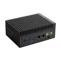
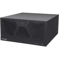
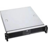
- (Industrial Computer Barebone)
- User's Manual
- Copyright © 2024 ASUSTeK Computer Inc. All Rights Reserved.
- Table of contents
- Chapter 1 System introduction
- Chapter 2 Motherboard information
- Chapter 3 BIOS setup
- Advanced menu 3-17
- Appendix
- Safety information
- Electrical safety
- Operation safety
- Lithium-Ion Battery Warning
- Restricted Access Location
- About this guide
- Audience
- How this guide is organized
- Chapter 1: System introduction
- Chapter 2: Motherboard info
- Chapter 3: BIOS setup
- Conventions used in this guide
- Where to find more information
- ASUS Website
- Optional Documentation
- System package contents
- Chapter 1
- Welcome!
- Brief introduction
- Front panel and rear panel
- Internal components
- Mounting the chassis
- Chapter 2
- Motherboard layout
- Central Processing Unit (CPU)
- System memory
- Jumpers
- Clear RTC RAM (2-pin CLRTC)
- Connector type
- To erase the RTC RAM:
- COM Ring/+5V/+12V selection jumper (6-pin COM1/2\_SEL)
- Chassis Intrusion header (4-1 pin CHASSIS)
- Internal connectors
- LPT header (26-1 pin LPT)
- General Purpose Input/Output connector (GPIO\_CON)
- USB 2.0 headers (USB7 / USB8 / USB914)
- CPU and Chassis Fan headers (4-pin CPU\_FAN, 4-pin CHA\_FAN)
- TPM header (14-1 pin TPM)
- System Panel header (10-1 pin F\_PANEL)
- - System power LED (2-pin +PWR\_LED)
- • Hard disk drive activity LED (2-pin +HDD\_LED)
- • ATX power button/soft-off button (2-pin PWR\_BTN)
- - Reset button (2-pin RESET)
- SATA 6.0Gb/s port (7-pin SATA6G\_1-4)
- Speaker header (4-pin SPEAKER)
- M.2 socket 3
- NOTES:
- COM Debug header
- Keyboard and Mouse Port connector (8-pin KBMS\_CON)
- Serial Port headers (10-1 pin COM3-6)
- Front Panel Audio header (10-1 pin AAFP)
- IMPORTANT!
- ATX Power connectors (24-pin ATX\_PWR, 4-pin ATX12V)
- Slots
- PCI Express x16 slot
- PCI Express x4 slots
- PCI slots
- Chapter 3
- BIOs setup
- BIOS setup program
- Entering BIOS Setup at startup
- To enter BIOS Setup at startup:
- Entering BIOS Setup after POST
- To enter BIOS Setup after POST:
- IMPORTANT:
- BIOS menu screen
- Menu bar
- Main menu
- Language [English]
- System Date [Day MM/DD/YYYY]
- System Time [HH:MM:SS]
- Security
- Administrator Password
- To set an administrator password:
- To change an administrator password:
- User Password
- To set a user password:
- To change a user password:
- Ai Tweaker menu
- CPU Power Enhancement
- CPU Core Ratio
- 1-Core Ratio Limit
- 2-Core Ratio Limit
- 3-Core Ratio Limit
- 4-Core Ratio Limit
- 5-Core Ratio Limit
- 6-Core Ratio Limit
- DRAM Odd Ratio Mode
- DRAM Frequency
- Power-saving & Performance Mode
- DRAM Timing Control
- Skew Control
- ODT RTT WR (CHA)
- ODT RTT PARK (CHA)
- ODT RTT NOM (CHA)
- ODT RTT WR (CHB)
- ODT RTT PARK (CHB)
- ODT RTT NOM (CHB)
- ODT\_READ\_DURATION
- ODT\_READ\_DELAY
- ODT\_WRITE\_DURATION
- Read MPR Training
- Receive Enable Training
- Jedec Write Leveling
- Early Write Time Centering 2D
- Early Read Time Centering 2D
- Write Timing Centering 1D
- Write Voltage Centering 1D
- Read Timing Centering 1D
- DIMM ODT Training
- Max RTT\_WR
- DIMM RON Training
- Write Drive Strength/Equalization 2D
- Write Slew Rate Training
- Read ODT Training
- Read Equalization Training
- Read Amplifier Training
- Write Timing Centering 2D
- Read Timing Centering 2D
- Command Voltage Centering
- Write Voltage Centering 2D
- Read Voltage Centering 2D
- Late Command Training
- Round Trip Latency
- Turn Around Timing Training
- Rank Margin Tool
- Memory Test
- DIMM SPD Alias Test
- Receive Enable Centering 1D
- Retrain Margin Check
- Write Drive Strength Up/Dn independently
- Third Timings
- tRDRD\_sg
- tRDRD\_dg
- tRDWR\_sg
- tRDWR\_dg
- tWRWR\_sg
- tWRWR\_dg
- tWRRD\_sg
- tWRRD\_dg
- tRDRD\_dr
- tRDRD\_dd
- tRDWR\_dr
- Training Profile
- DLLBwEn
- SPD Write Disable
- DIGI+ VRM
- CPU Load-line Calibration
- CPU Power Phase Control
- CPU VRM Thermal Control
- CPU Graphics Load-Line Calibration
- Internal CPU Power Management
- Intel(R) SpeedStep(tm)
- Turbo Mode
- Turbo Mode Parameters
- Long Duration Package Power Limit
- Package Power Time Window
- Short Duration Package Power Limit
- IA AC Load Line
- IA DC Load Line
- CPU Core/Cache Current Limit Max.
- CPU Graphics Current Limit
- Min. CPU Cache Ratio
- Max. CPU Cache Ratio
- Max. CPU Graphics Ratio
- DRAM Voltage
- DRAM REF Voltage Control
- DRAM CTRL REF Voltage
- DRAM DATA REF Voltage on CHB
- Advanced menu
- Platform Misc Configuration
- PCI Express Native Power Management [Disabled]
- Native ASPM [Disabled]
- PCH - PCI Express options
- PCH DMI ASPM [Disabled]
- ASPM [Disabled]
- L1 Substates [Disabled]
- PCI Express Clock Gating [Enabled]
- SA - PCI Express options
- DMI Link ASPM Control [Disabled]
- PEG-ASPM [Disabled]
- CPU Configuration
- Software Guard Extensions [Software Controlled]
- Hardware Prefetcher [Enabled]
- Adjacent Cache Line Prefetcher [Enabled]
- Intel Virtualization Technology [Disabled]
- Active Processor Cores [All]
- Hyper-threading [Enabled]
- Thermal Monitor [Enabled]
- CPU Power Management Control
- Intel(R) SpeedStep(tm) [Auto]
- Intel(R) Speed Shift Technology [Auto]
- Turbo Mode [Enabled]
- CPU C-states [Auto]
- CPU C3 Report [Enabled]
- CPU C6 Report [Disabled]
- CPU C7 Report [Disabled]
- CPU C8 Report [Disabled]
- CPU C9 Report [Disabled]
- CPU C10 Report [Disabled]
- Package C State Limit [Auto]
- CFG Lock [Disabled]
- System Agent (SA) Configuration
- VT-d [Disabled]
- Above 4G Decoding [Disabled]
- Memory Configuration
- Memory Remap [Enabled]
- Graphics Configuration
- Primary Display [Auto]
- iGPU Multi-Monitor [Disabled]
- DVMT Pre-Allocated [64M]
- RC6(Render Standby) [Auto]
- PEG Port Configuration
- PCIEX16\_1 Link Speed [Auto]
- PCH Configuration
- PCI Express Configuration
- PCIe Speed [Auto]
- IOAPIC 24-119 Entries [Enabled]
- System Time and Alarm Source [ACPI Time and Alarm Device]
- PCH Storage Configuration
- SATA Controller(s) [Enabled]
- SATA Mode Selection [AHCI]
- Aggressive LPM Support [Disabled]
- Smart Self Test [Enabled]
- SATA6G\_1\~4(Gray) [Enabled]
- SATA6G\_1\~4 Hot Plug [Disabled]
- PCH-FW Configuration
- TPM Device Selection [Discrete TPM]
- Onboard Devices Configuration
- HD Audio Controller [Enabled]
- Intel LAN Controller [Enabled]
- Intel PXE OPROM [Disabled]
- Realtek LAN Controller [Enabled]
- Realtek PXE OPROM [Disabled]
- USB power delivery in Soft Off state (S5) [Disabled]
- PCIEX4\_3 Configuration
- Serial Port 1 Configuration
- Serial Port [Enabled]
- COM1 Control [RS232]
- Serial Port 2 Configuration
- COM2 Control [RS232]
- Serial Port 3 Configuration
- Serial Port 4 Configuration
- Serial Port 5 Configuration
- Serial Port 6 Configuration
- Parallel Port Configuration
- Parallel Port [Enabled]
- Change Settings [Auto]
- Device Mode [STD Printer Mode]
- APM Configuration
- ErP Ready [Disabled]
- CEC Ready [Disabled]
- Restore AC Power Loss [Power Off]
- Power On By PCI-E/PCI [Disabled]
- Power On By Ring [Disabled]
- Power On By RTC [Disabled]
- Serial Console Redirection
- COM1(\~6)
- Console Redirection
- Console Redirection Settings
- Terminal Type
- Bits per second
- Data Bits
- Parity
- Stop Bits
- Flow Control
- VT-UTF8 Combo Key Support
- Recorder Mode
- Resolution 100x31
- Putty KeyPad
- Serial Port for Out-of-Band Management / Windows Emergency Management Services (EMS)
- Out-of-Band Mgmt Port
- PCI Subsystem Settings
- SR-IOV Support [Disabled]
- USB Configuration
- Legacy USB Support [Enabled]
- XHCI Hand-off [Disabled]
- USB Single Port Control
- Network Stack Configuration
- Network Stack [Disabled]
- Ipv4 PXE Support [Enabled]
- Ipv6 PXE Support [Enabled]
- HDD Secure Erase
- HDD/SSD SMART Information
- Monitor menu
- CPU / MotherBoard Temperature [xxx°C/xxx°F]
- CPU / Chassis Fan Speed [xxxx RPM] or [Ignore] / [N/A]
- CPU Core Voltage, 3.3V Voltage, 5V Voltage, 12V Voltage
- Q-Fan Configuration
- Q-Fan Tuning
- CPU Q-Fan Control [PWM Mode]
- CPU Fan Step Up [0 sec]
- CPU Fan Step Down [0 sec]
- CPU Fan Speed Low Limit [200 RPM]
- CPU Fan Profile [Standard]
- CPU Upper Temperature [70]
- CPU Fan Max. Duty Cycle(%) [100]
- CPU Middle Temperature [25]
- CPU Fan Middle Duty Cycle(%) [20]
- CPU Lower Temperature [20]
- CPU Fan Min. Duty Cycle(%) [20]
- Chassis Fan(s) Configuration
- Chassis Fan Q-Fan Control [PWM mode]
- Chassis Fan Q-Fan Source [CPU]
- Chassis Fan Step Up [0 sec]
- Chassis Fan Step Down [0 sec]
- Chassis Fan Speed Low Limit [200 RPM]
- Chassis Fan Profile [Standard]
- Chassis Fan Upper Temperature [70]
- Chassis Fan Max. Duty Cycle(%) [100]
- Chassis Fan Middle Temperature [25]
- Chassis Fan Middle Duty Cycle(%) [20]
- Chassis Fan Lower Temperature [20]
- Chassis Fan Min. Duty Cycle(%) [20]
- Chassis Fan Middle Temperature [45]
- Chassis Fan Middle Duty Cycle(%) [60]
- Chassis Fan Lower Temperature [40]
- Chassis Fan Min. Duty Cycle(%) [60]
- Allow Fan Stop [Disabled]
- Chassis Intrusion Detection Support [Disabled]
- Boot menu
- Boot Configuration
- Fast Boot [Enabled]
- Next Boot after AC Power Loss [Normal Boot]
- Boot Logo Display [Auto]
- POST Delay Time [3 sec]
- Bootup NumLock State [On]
- Wait for 'F1' If Error [Enabled]
- Option ROM Messages [Force BIOS]
- Interrupt 19 Capture [Disabled]
- AMI Native NVMe Driver Support [Enabled]
- CSM (Compatibility Support Module)
- Launch CSM [Enabled]
- Boot Device Control [UEFI and Legacy OPROM]
- Boot from Network Devices [Legacy only]
- Boot from Storage Devices [Legacy Only]
- Boot from PCI-E / PCI Expansion Devices [Legacy Only]
- Secure Boot
- OS Type [Other OS]
- Key Management
- Clear Secure Boot keys
- Save all Secure Boot variables
- PK Management
- Save to File
- Set New Key
- Delete Key
- KEK Management
- Append Key
- DB Management
- DBX Management
- Boot Option Priorities
- Boot Override
- Tool menu
- ASUS EZ Flash 3 Utility
- ASUS SPD Information
- Event Log
- Exit menu
- Load Optimized Defaults
- Save Changes & Reset
- Discard Changes & Exit
- Launch EFI Shell from USB drives
- Notices
- FCC Compliance Information
- HDMI Trademark Notice
- Compliance Statement of Innovation, Science and Economic Development Canada (ISED)
- KC: Korea Warning Statement
- ASUS Recycling/Takeback Services
- Service and Support
Brand : ASUS
Model : EBS-A710
Category : Industrial computer