
VSX-LX805 - AV receiver KLIPSCH - Free user manual and instructions
Find the device manual for free VSX-LX805 KLIPSCH in PDF.


| Brand | Klipsch |
| Model | VSX-LX805 |
| Product Type | AV Receiver |
| Amplifier Channels | 11 channels |
| Rated Output Power (FTC) | 150 W per channel (8 ohms, 20 Hz-20 kHz, 0.08% THD) |
| Maximum Effective Output Power | 260 W per channel (6 ohms, 1 kHz, 1 ch driven, 10% THD) |
| HDMI Inputs/Outputs | 7 inputs (1 front) / 3 outputs (MAIN, SUB, ZONE2) |
| HDMI Bandwidth | 40 Gbps (main inputs and outputs) |
| Video Features | 8K/60p, 4K/120p, HDR10+, Dolby Vision, ALLM, VRR, QFT, DSC |
| Audio Formats | Dolby Atmos, DTS:X, IMAX Enhanced, 192 kHz/24-bit PCM, DSD |
| Room Calibration | Dirac Live, MCACC Pro |
| Network Connectivity | Wi-Fi 5 (802.11ac), Ethernet (100BASE-TX), Bluetooth 4.2 |
| Streaming Services | Spotify, TIDAL, Amazon Music, AirPlay 2, DTS Play-Fi, Internet Radio |
| Multi-Zone | Zone 2 (HDMI/analog), Zone 3 (analog), Zone B (line out) |
| Speaker Impedance | 4 Ω - 16 Ω |
| Subwoofer Outputs | 4 (SW1 A/B, SW2 A/B) |
| Inputs (Audio) | 6 analog (including phono and XLR), 5 digital (2 coaxial, 3 optical) |
| USB Ports | 2 (front 0.5A, rear 1A) |
| Dimensions (W x H x D) | 435 mm x 185.5 mm x 468 mm (17.125" x 7.3125" x 18.4375") |
| Weight | 21.5 kg (47.4 lbs) |
| Power Consumption (Max) | 1190 W (NA model: 1095 W) |
| Standby Power | 0.2 W (full standby), 1.9 W (network standby) |
| Warranty | Consult official Klipsch documentation |
Frequently Asked Questions - VSX-LX805 KLIPSCH
User questions about VSX-LX805 KLIPSCH
0 question about this device. Answer the ones you know or ask your own.
Ask a new question about this device
Download the instructions for your AV receiver in PDF format for free! Find your manual VSX-LX805 - KLIPSCH and take your electronic device back in hand. On this page are published all the documents necessary for the use of your device. VSX-LX805 by KLIPSCH.
USER MANUAL VSX-LX805 KLIPSCH

Firmware Update

Troubleshooting

Supplementary Information

Reducing the Power Consumption in Standby State
When the following functions are enabled, the power consumption in standby state increases. To reduce the power consumption in standby state, check each setting and set the functions to "Off".
-HDMI CEC (→p146)
-HDMI Standby Through (→p146)
- USB Power Out at Standby (→p148)
- Network Standby (→p149)
- Bluetooth Wakeup (→p149)
☐ Detailed contents (Next page)





Before starting the procedure 7
Firmware Update 8
Update Information of the firmware 8
Checking the Firmware Version of the Unit 8
Firmware Update Procedure 8
Part Names 11
Front Panel (North American and Taiwanese models) 11
Front Panel (European, Australian and Asian models) 13
Display 15
Rear Panel 16
Remote Controller 18
Inputting Characters 20
Speaker Layout
The listening room and the speaker layout 22
5.1 Channel System 23
7.1 Channel System 24
5.1.2 Channel System 25
7.1.2 Channel System 26
5.1.4 Channel System 27
7.1.4 Channel System 30
Speaker Installation
Setting Up the Speakers 33
Speaker Connections
Speakers you can use with this unit and cable connections 40
Connect the Subwoofer 41
Connecting a Power Amplifier 61
Connections
Notes regarding connections with HDMI cables 63
Connections 63
Connecting the TV 64 To ARC/eARC TV 64 To Non-ARC TV 64
Connecting the SUB Monitor 66 SUB Monitor 66
Connecting Playback Devices 67 Connections to BD/DVD and GAME with HDMI jacks 67 Connecting a BD/DVD without HDMI Jack Mounted 68 Connecting an Audio Component 69 Connecting a Video Camera, etc. 70
Connecting a TV or Integrated Amplifier in a separate room (Multi-zone) 71 Connecting a TV (ZONE 2) 71 Connecting an Integrated Amplifier (ZONE 2) 72 Connecting an Integrated Amplifier (ZONE 3) 73





Connecting Antennas (North American and
Taiwanese models) 74
Network Connection 75
Connecting External Control Devices 76
IR IN/OUT port 76
12V TRIGGER OUT jack 77
Connecting the Power Cord 78
Playback
Basic Operations 80
Turning the power on 80
Selecting a source to play 80
Adjusting the volume 81
Using the linking function (HDMI CEC) 81
Listening Mode 83
Selecting a Listening mode 83
BLUETOOTH® Playback 84
Playing audio from BLUETOOTH wireless technology enabled devices with this unit 84
Transmitting audio from this unit to BLUETOOTH wireless technology enabled devices 86
Listening To the Radio (North American and
Taiwanese models) 88
Listening To the AM/FM Radio 88
Presetting a Radio Station 90
AV Adjust 91
Spotify 95
AirPlay® 96
Basic Operations 96
Playing Back on multiple devices (AirPlay2) 97
DTS Play-Fi® 98
Playing Back 98
Amazon Alexa 99
Registering this unit with an Amazon account 99
Operating this unit 100
Amazon Music 101
Registering This Unit with Amazon Music 101
Playing Amazon Music using the Pioneer Remote App 102
Playing Amazon Music using the remote controller 102
TIDAL 103
Registering this unit with TIDAL 103
Playing TIDAL 103
Connecting the Sonos System for Playback 104
Necessary Equipment 104
How to Connect This Unit and Sonos Connect 104
Setting Up 104
Playing Sonos on This Unit 105
Internet Radio 106






Playing Back 106
Multi-zone 108
Playing Back (ZONE 2) 109
Playing Back (ZONE 3) 111
Using PERSONAL PRESET 113
AV Direct Mode 115
Using "AV Direct" 115
Using "AV Direct Net Off" 115
Playing music files saved on a USB storage device 116
USB Storage Device Requirements 117
Music Server 118
Music Server notes 118
Windows Media® Player 12 settings 118
Playing Back 119
Play Queue 121
Adding Play Queue Information 121
Sort and Delete 121
Playing Back 122
Connecting a transmitter for playback 123
Connections 123
Setting Up 123
Playing Back 123
Setup
System Setup 126
Menu list 126
Input/Output Assign 128
Speaker 134
Audio Adjust 141
Source 144
Hardware 146
Multi Zone 152
Miscellaneous 155
MCACC Pro 157
Menu operations 157
Full Auto MCACC 158
Manual MCACC 160
MCACC Data Check 165
Data Management 166
Network/Bluetooth 167
Menu operations 167
Network 168
Bluetooth 171
Web Setup 174
Menu operations 174
Initial Setup with Auto Start-up Wizard 175
Operations 175





- Speaker Setup 176
- Multi Zone Sound Check 177
- ARC Setup 177
- Room EQ 177
Pioneer Remote App 181
Main features 181
Initial Setup 181
Dirac Live 182
Measuring with Dirac Live 182
Using Dirac Live 183
Manual Adjust 184
Troubleshooting
Before starting the procedure 186
When the unit is operating erratically 187
Troubleshooting 188
Appendix
Speaker Layouts and Selectable Listening Modes 200
Input Formats and Selectable Listening Modes 203
Listening Mode Effects 207
Speaker combinations 212
General Specifications 214



Before starting the procedure
What's in the box

natural_image
Line drawing of a rectangular electronic device with two side ports and a central screen (no text or symbols)


① Main unit (1)
② Remote controller (RC-990R) (1), Batteries (AAA/R03) (2)
③ Speaker setup microphone (1)
• Used during Initial Setup.
4 Indoor FM antenna (North American and Taiwanese models) (1)
⑤ AM loop antenna (North American and Taiwanese models) (1)
⑥ Power cord (1)
- Initial Setup Guide (1)
* This document is an online instruction manual. This is not supplied with the product.
Note
- Connect speakers with an impedance of 4 to 16 .
- The power cord must be connected only after all other connections are completed.
• We will not accept any responsibility for damage arising from the connection with equipment manufactured by other companies. - Network services and content that can be used may no longer be available if new functions are added by updating firmware or the service providers terminate their services. Also, available services may differ depending on your area.
- Details on the firmware update will be posted on our website and through other means at a later date.
- The illustrations in this manual use those of North American models unless otherwise mentioned.
- Specifications and appearance are subject to change without prior notice.



Firmware Update
Disclaimer: The program and accompanying online documentation are furnished to you for use at your own risk.
Our company will not be liable and you will have no remedy for damages for any claim of any kind whatsoever concerning your use of the program or the accompanying online documentation, regardless of legal theory, and whether arising in tort or contract.
In no event will our company be liable to you or any third party for any special, indirect, incidental, or consequential damages of any kind, including, but not limited to, compensation, reimbursement or damages on account of the loss of present or prospective profits, loss of data, or for any other reason whatsoever.
Update Information of the firmware
For the latest firmware contents and the firmware version, visit website.
- When this unit is connected to the network, notifications of firmware updates may be displayed. To update the firmware, select "Update Now" with the cursor buttons of the remote controller and press ENTER. The unit automatically enters standby mode after "Completed!" is displayed, and the update is completed.
Checking the Firmware Version of the Unit
To confirm the firmware version of your product, press the button on the remote controller to display the Home screen, and refer to "System Setup" - "Miscellaneous" - "Firmware Update" - "Version" (→p155).



Firmware Update Procedure
Updating can take about 20 minutes. Existing settings are maintained.
Updating the Firmware via Network
- While updating the firmware, do not do the following:
- Disconnecting and reconnecting cables, USB storage device, speaker setup microphone or headphones, or performing operations on the unit such as turning the power off
- Accessing this unit from a PC or smartphone using their applications
- Turn off control devices (PC etc.) connected to the network.
- Stop an Internet radio, USB storage device, or server content being played.
- If the multi-zone function is active, turn it off.
- If "HDMI CEC" is set to "On", set it to "Off".
- Press to display the Home screen. Next, select "System Setup" - "Hardware" - "HDMI", press ENTER, select "HDMI CEC" and select "Off".
* The descriptions may differ from the actual on-screen displays, however, operations and functions are the same.
Update
- Turn on the power of the unit and wait for about 20 seconds.
- Press the button on the remote controller, select "System Setup" -
"Miscellaneous" - "Firmware Update" - "Update via NET" with the cursors in order, then press ENTER. - If "Firmware Update" is not available for selection, wait until the system has started.
- "Update via NET" will not be available for selection if the firmware of the unit is the latest.
- Press ENTER with "Update" selected, and start update.
"Completed!" is displayed when updating is completed.
Check the progress on the display of the unit. - Press \$STANDBY/ON on the main unit to turn the unit into standby mode. The process is completed, and your firmware is updated to the latest version.
- Do not use on the remote controller.


If an Error Message is Displayed
If an error occurs, "*-* * Error!" is displayed on the display of the unit. ("*" represents an alphanumeric character.) Refer to the following descriptions and check.
Error Code
- *-01, *-10:
Ethernet cable not found. Connect the Ethernet cable properly. - *-02, *-03, *-04, *-05, *-06, *-11, *-13, *-14, *-16, *-17, *-18, *-20, *-21:
Internet connection error. Check the following: - Whether the router is turned on
- Whether this unit and the router are connected via the network
Unplug and plug the power cords of this unit and the router. This may solve the problem. If you are still unable to connect to the Internet, the DNS server or proxy server may be temporarily down. Check the server operation status with your Internet service provider.
After removing the power plug once, insert it to the outlet, and then start the operation from the beginning.
- Others:




Updating via USB
- Save only the updating data on the USB storage device. Delete any other data.
- While updating the firmware, do not do the following:
- Disconnecting and reconnecting cables, USB storage device, speaker setup microphone or headphones, or performing operations on the unit such as turning the power off
- Accessing this unit from a PC or smartphone using their applications
- Prepare a 1 GB or larger USB storage device. The format of USB storage devices supports FAT16 or FAT32 file system format.
– Media inserted into a USB card reader may not be used for this function.
– USB storage devices equipped with the security function are not supported.
– USB hubs and USB devices equipped with the hub function are not supported. Do not connect these devices to the unit. - Turn off control devices (PC etc.) connected to the network.
- Stop any playing Internet radio, USB storage device, or server content.
- If the multi-zone function is active, turn it off.
- If "HDMI CEC" is set to "On", set it to "Off".
- Press to display the Home screen. Next, select "System Setup" -
"Hardware" - "HDMI", press ENTER, select "HDMI CEC" and select "Off".
* Depending on the USB storage device or its content, long time may be required for loading, the content may not be loaded correctly, or power may not be supplied correctly. - Our company will not be liable whatsoever for any loss or damage of data, or storage failure arising from the use of the USB storage device. Please note this in advance.
* The descriptions may differ from the actual on-screen displays, however, operations and functions are the same.
Update
-
Connect the USB storage device to your PC.
-
Download the firmware file from the our company's website to your PC and unzip.
Firmware files are named as below.
PIOAVR****_R****.zip
Unzip the file on your PC. The number of unzipped files and folders varies depending on the model.
- Copy all unzipped files and folders to the root folder of the USB storage device.


• Make sure to copy the unzipped files.
- Connect the USB storage device to the USB port of this unit.
- If an AC adapter is supplied with the USB storage device, connect the AC adapter, and use it with a household outlet.
- If the USB storage device has been partitioned, each section will be treated as an independent device.
-
Turn on the power of the unit and wait for about 20 seconds.
-
Press the Button on the remote controller, select "System Setup" - "Miscellaneous" - "Firmware Update" - "Update via USB" with the cursors in order, then press ENTER.
- If "Firmware Update" is not available for selection, wait until the system has started.
- "Update via USB" will not be available for selection if the firmware of the unit is the latest.
- Press ENTER with "Update" selected, and start update.
"Completed!" is displayed when updating is completed.
- Check the progress on the display of the unit.
- During the update, do not turn the power off, or disconnect or reconnect the USB storage device.
-
Disconnect the USB storage device from the unit.
-
Press ⒸSTANDBY/ON on the main unit to turn the unit into standby mode. The process is completed, and your firmware is updated to the latest version.
- Do not use on the remote controller .
If an Error Message is Displayed
If an error occurs, "*-* * Error!" is displayed on the display of the unit. ("* " represents an alphanumeric character.) Refer to the following descriptions and check.
Error Code
• *-01, *-10;
The USB storage device cannot be recognized. Check if the USB storage device or USB cable is securely inserted to the USB port of the unit.
Connect the USB storage device to an external power source if it has its own power supply.
• *-05, *-13, *-20, *-21;
The firmware file is not present in the root folder of the USB storage device, or the firmware file is for another model. Retry from the download of the firmware file.
- Others:
After removing the power plug once, insert it to the outlet, and then start the operation from the beginning.






Part Names
Front Panel (North American and Taiwanese models)
European, Australian and Asian models (→p13)

① INPUT SELECTOR dial: Switch the input to be played.
② FL OFF indicator: Lights up when the display is turned off by repeatedly pressing the DIMMER button on the remote controller.
③ Display (→p15)
4 NETWORK indicator: This lights when "NET" is selected with the input selector and the unit is connected to the network. Lights up when any of the following functions is working or




enabled in standby state of this unit. When this indicator is lighting, the power consumption in standby state increases, however, the increase in power consumption is minimized by entering the HYBRID STANDBY mode where only the essential circuits operate. It does not light when ZONE 2/ZONE 3 is on, however.
-HDMI CEC (→p146)
– HDMI Standby Through (→p146)
- USB Power Out at Standby (→p148)
- Network Standby (→p149)
- Bluetooth Wakeup ( →p149)
⑤ Remote control sensor: Receives signals from the remote controller.
- The signal range of the remote controller is within about 16'/5 m, at an angle of 20° on the perpendicular axis and 30° to either side.
⑥ MCACC PRO indicator: This lights when you have enabled the speaker calibration made with MCACC. (→p158, p180)
⑦ MASTER VOLUME
8 STANDBY/ON button: When the power is turned on, the periphery of the button lights up. It also lights up when ZONE 2/ZONE 3 is turned on.
⑨ Front flap
⑩ PHONES jack: Headphones with a standard plug (ø1/4" / 6.3 mm) are connected.
⑪ SETUP MIC jack: Connect the supplied speaker setup microphone. (→p158, p180)
⑫ USB port: A USB storage device is connected so that music files stored in it can be played. Supply of power to USB devices while in the standby mode is not supported. (→p116)
⑬ AUX INPUT HDMI jack: Connect a video camera, etc. using an HDMI cable. (→p70)



Front Panel (North American and Taiwanese models)
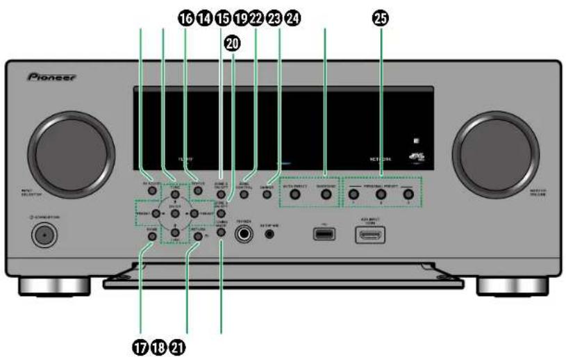
14 AV ADJUST button: Settings such as "HDMI" and "Audio" can be made quickly during play on the TV screen. (→p91)
15 Cursor buttons (+/ + *) and ENTER button: Select the item with the cursors, and press ENTER to confirm. Use them to tune to stations when using TUNER. (→p88)
⑯ STATUS button: Switches the information on the display. (→p82)
⑰ HOME MENU button: Displays the Home.




(→p126, p157, p167)
⑬ RETURN button: Returns the display to the previous state.
⑲ ZONE 2 ON/OFF button: Turns ZONE 2 ON/OFF. (→p109)
⑳ ZONE 3 ON/OFF button: Turns ZONE 3 ON/OFF. (→p111)
② TUNING MODE button: Switches the tuning mode. (→p88)
② ZONE CONTROL button: Controls the multi-


Front Panel (European, Australian and Asian models)
North American and Taiwanese models (→p11)

① INPUT SELECTOR dial: Switch the input to be played.
② FL OFF indicator: Lights up when the display is turned off by repeatedly pressing the DIMMER button on the remote controller.
③ Display (→p15)
4 NETWORK indicator: This lights when "NET" is selected with the input selector and the unit is connected to the network. Lights up when any of the following functions is working or
enabled in standby state of this unit. When this indicator is lighting, the power consumption in standby state increases, however, the increase in power consumption is minimized by entering the HYBRID STANDBY mode where only the essential circuits operate. It does not light when ZONE 2/ZONE 3 is on, however.
-HDMI CEC (→p146)
- HDMI Standby Through (→p146)
- USB Power Out at Standby (→p148)
- Network Standby (→p149)
- Bluetooth Wakeup (→p149)
⑤ Remote control sensor: Receives signals from the remote controller.
The signal range of the remote controller is within about 16°/5 m, at an angle of 20° on the perpendicular axis and 30° to either side.
⑤ MCACC PRO indicator: This lights when you have enabled the speaker calibration made with MCACC. (→p158, p180)
⑦ MASTER VOLUME
8 dSTANDBY/ON button: When the power is turned on, the periphery of the button lights up. It also lights up when ZONE 2/ZONE 3 is turned on.
9 Front flap
⑩ PHONES jack: Headphones with a standard plug (ø1/4" / 6.3 mm) are connected.
⑪ SETUP MIC jack: Connect the supplied speaker setup microphone. (→p158, p180)
⑫ USB port: A USB storage device is connected so that music files stored in it can be played. Supply of power to USB devices while in the standby mode is not supported. (→p116)
⑬ AUX INPUT HDMI jack: Connect a video camera, etc. using an HDMI cable. (→p70)






Front Panel (European, Australian and Asian models)

14 AV ADJUST button: Settings such as "HDMI" and "Audio" can be made quickly during play on the TV screen. (→p91)
⑮ Cursor buttons (+/ + / + ) and ENTER button: Select the item with the cursors, and press ENTER to confirm.
16 STATUS button: Switches the information on the display. (→p82)
⑰ HOME MENU button: Displays the Home.
(→p126, p157, p167)
18 RETURN button: Returns the display to the previous state.
⑲ ZONE 2 ON/OFF button: Turns ZONE 2 ON/OFF. (→p109)
⑳ ZONE 3 ON/OFF button: Turns ZONE 3 ON/OFF. (→p111)
② DIRAC LIVE button: Selects slots where the measurement results of Dirac Live are saved. (→p93)
② ZONE CONTROL button: Controls the multi-
zone function. (→p108)
DIMMER button: You can switch the display off or adjust the brightness of the display in three steps.
② LISTENING MODE button: Switches the listening mode. (→p83)
25 PERSONAL PRESET 1/2/3 buttons: Registers the current setting conditions such as input selector, listening mode, etc. or call the registered settings. (→p113)




Display

input is selected.
③ Lights according to the type of input digital audio signal and the listening mode.
4 Lights in the following conditions. TUNED: Receiving AM/FM radio * STEREO: Receiving FM stereo. * SLEEP: Sleep timer is set. (→p148) AUTO STBY: Auto Standby is set. (→p148) * North American and Taiwanese models
⑤ Displays the audio output destination. A: Outputs audio only to ZONE A. B: Outputs audio only to ZONE B. AB: Outputs audio to both ZONE A and ZONE B.
6 Lights when headphones are connected. 7 Blinks when muting is on. 8 Displays various information of the input signals. 9 Lights when adjusting the volume. 10 Speaker/Channel display: Displays the output channel that corresponds to the selected listening mode.
① ▲ /▼ /◄ /►: These may light when performing operations while "NET" or "USB" is selected with the input selector. ▲ Light when there are multiple folders or files that are available to be selected. ◀ Light when text information does not fit with the range provided by "B".
② Lights in the following conditions.
Z2/Z3: ZONE 2/ZONE 3 is on.
*: Connected by BLUETOOTH.
*: Connected by Wi-Fi.


NET: Lights when connected to the network with the "NET" input selector. It will blink if incorrectly connected to the network.
USB: Lights when the "USB" input selector is selected, a USB device is connected and the USB input is selected. It will blink if the USB device is not properly connected.
HDMI: HDMI signals are input and the HDMI input is selected.
DIGITAL: Digital signals are input and the digital


Rear Panel

① DIGITAL AUDIO IN OPTICAL/COAXIAL jacks: Input TV or AV component digital audio signals with a digital optical cable or digital coaxial cable.
② ANTENNA AM LOOP/FM UNBAL 75 Ω terminal: (North American and Taiwanese models) Connect the supplied antennas.
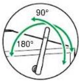
③ Wireless antenna: Used for Wi-Fi connection or when using a BLUETOOTH enabled device. Adjust the angles according to the connection status.
4 HDMI OUT jacks: Transmit video signals and audio signals with an HDMI cable connected to a monitor such as a TV or projector.
⑤ HDMI IN jacks: Transmit video signals and audio signals with an HDMI cable connected to an AV component.
⑥ NETWORK port: Connect to the network with an Ethernet cable.
⑦ USB port: Connect a USB storage device to play music files (→p116). You can also supply power (5 V/1 A) to USB devices with a USB cable.
⑧ AC IN: The supplied power cord is connected.






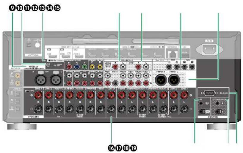
9 AUDIO IN Jacks: Input AV component audio signals with an XLR balanced cable or analog audio cable.
⑩ SIGNAL GND terminal: Connect the ground wire of the turntable.
⑪ COMPONENT VIDEO IN Jacks: Input AV component video signals with a component video cable. (Compatible only with 480i or 576i resolution.)
VIDEO IN jacks: Input AV component video
signals with an analog video cable.
⑫ ZONE 2 PRE/LINE OUT jacks: Output audio signals with an analog audio cable connected to an integrated amplifier in a separate room (ZONE 2).
ZONE B LINE OUT Jacks: Simultaneously output the same audio source as the speakers (ZONE A) connected to this unit by connecting this unit to wireless headphones, wireless speaker transmitter, etc., using an analog audio
cable.
⑬ ZONE 3 PRE/LINE OUT jacks: Output audio signals with an analog audio cable connected to an integrated amplifier in a separate room (ZONE 3).
14 SUBWOOFER PRE OUT jacks: Connect a powered subwoofer with a subwoofer cable. See "Connect the Subwoofer" (→p41) for details.
⑮ PREOUT jacks: Connect a power amplifier.
(→p61)
16 SPEAKERS terminals: Connect speakers with speaker cables. (Support banana plugs. Use a plug 4 mm in diameter. Y plug connection is not supported.)
⑰ IR IN/OUT port: Connect a remote control receiver unit. (→p76)
18 12V TRIGGER OUT A/B jack: Connect a device equipped with a 12V trigger input jack to enable power link operation between the device and this unit. (→p77)
19 RS-232C port: Connect a home control system equipped with an RS-232C port. For installing a home control system, contact the specialized stores.



Remote Controller Remote Controller

① ⏻STANDBY/ON button
② Input selector buttons: Switches the input to be played.
③ PERSONAL PRESET 1/2/3 buttons: Registers the current setting conditions such as input selector, listening mode, etc. or call the registered settings. (→p113)
④ DIMMER button: You can switch the display off or adjust the brightness of the display in three steps.
⑤ (AV ADJUST) button: Settings such as "HDMI" and "Audio" can be made quickly during play on the TV screen. (→p91)
⑥ Cursor buttons and ENTER button: Select the item with the cursors, and press ENTER to confirm your selection. When the folder or file lists are not shown on one screen on the TV, press ◀ to change the screen.
⑦ Button: Displays the Home. (→p126, p157, p167)
⑧ SLEEP button: You can allow the unit to enter standby automatically when the specified time has elapsed. Select the time from "30 min", "60 min", "90 min" and "Off". When you do not want to turn the unit to standby automatically, select "Off". You can also set this by pressing the button on the remote controller to display the Home screen and selecting "System Setup" - "Hardware" - "Power Management" - "Sleep Timer" (-p148).
⑨ HDMI MAIN/SUB button: Select the HDMI OUT jack to output video signals from "MAIN", "SUB", and "MAIN+SUB".
10 MODE button: Switches between automatic tuning and manual tuning for AM/FM stations (→p88) (North American and Taiwanese models). Also, when an HDMI CEC function-
enabled AV component is connected to this unit, you can switch ⑰. Play buttons between "CEC MODE" and "RCV MODE" (normal mode).
11 + Fav button: Used to register AM/FM radio stations. (→p90) (North American and Taiwanese models)
⑫ (STATUS) button: Switches the information on the display.
⑬ button: Returns the display to the previous state.




Remote Controller

⑭ LISTENING MODE buttons: Selects a listening mode (→p83).
⑮ DIRAC button: Selects slots where the measurement results of Dirac Live are saved. (→p93)
⑯ TONE/DIALOG/SW buttons: Adjusts the sound quality of the speakers and volume level of the subwoofer.
TONE button: You can adjust the sound quality of the speakers.
- Press TONE repeatedly to select Treble or Bass and adjust the content. Treble: Enhances or moderates the high-tone range of the speakers. Bass: Enhances or moderates the low-tone range of the speakers.
- Press + or - for adjustment.
DIALOG button: Emphasizes movie dialogues and music vocals to listen to them more easily. It is effective to movie lines in particular. Also, it exerts the effect even if the center speaker is not used. Select a desired level from "1" (low) to "5" (high).
- Press DIALOG.
- Press + or - for adjustment. • Depending on the input source or listening mode setting, selection is not possible, or the desired effect may not be achieved.
SW button: Adjust the speaker level of the subwoofer while listening to the sound.
- Press SW.
- Press + or - to adjust the level between "-15.0 dB" and "+12.0 dB". • If you set the unit to the standby mode, the adjustments you made will be restored to
the previous statuses.
17 Play buttons: Used for playback operations for the Music Server (→p118) or USB device (→p116). Also, switching to "CEC MODE" with 10 MODE button allows you to operate an HDMI CEC function-enabled AV component. (Some devices may not be operated.)
18 ZONE 2/ZONE 3 HOLD button: Used to control the multi-zone function (→p108).
19 CH SEL button: You can check the volume level settings (→p140) for each of the speakers. You can also change the settings with the number ⑥ cursor buttons ◀.
20 S.RETRIEVER button: Enable Sound Retriever (→p92) and improve the quality of compressed audio.
② MUTE button: Temporarily mutes audio. Press the button again to cancel muting.
22 Volume buttons
⑳ button: You can start repeat or random play of the Music Server or USB.
CLEAR button: Deletes all characters you have entered when entering text on the TV screen.
24 LIGHT button): Turn the backlight of the remote controller On/Off. If 10 seconds elapse with no operations performed after turning it on, it will automatically turn off.






Inputting Characters
You can input characters or symbols on the keyboard displayed on the TV screen such as when inputting a password for Wi-Fi Setup (→p168) or naming a preset radio station (→p144).
- Select a character or symbol with the cursors ▲ /▼/ ◀ on the remote controller and press the ENTER button.
- When saving characters after input, select "OK" and press the ENTER button.


- Select "A/a" to switch between upper and lower cases. (Can also be switched with the MODE button on the remote controller.)
• To enter a space, select "ü" - To delete a character on the left of the cursor, select "
- To delete all the input characters, press the CLEAR button on the remote control.
- On the ZONE 2 playback screen, operate the remote controller while pressing and holding the ZONE 2 HOLD button. To delete all the input characters, only press the CLEAR button without pressing the ZONE 2 HOLD button.






Speaker Layout
This unit can be used in different ways, depending on the layout of the speakers you are installing. Select the speaker layout that suits the installation environment, then confirm the methods for installation and connection.
☐ Speaker layout (→p23)
☐ Speaker Installation (→p33)
☐ Speaker Connections (→p39)
☐ Speaker Combinations (→p212)







The listening room and the speaker layout
Speaker Layout

flowchart
graph TD
    A["Zone A (Main Room)"] --> B["Zone 2"]
    A --> C["Zone 3"]
    B --> D["Display Device 1"]
    B --> E["Display Device 2"]
    C --> F["Display Device 3"]
    style A fill:#f9f,stroke:#333
    style B fill:#ccf,stroke:#333
    style C fill:#ccf,stroke:#333
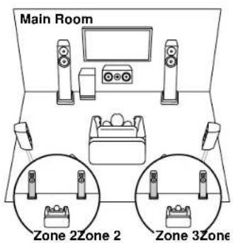
① ZONE A Speakers
The speaker system set up in the main room (where this unit is located).
② ZONE 2 Speakers
The 2 ch speaker system set up in a separate room (ZONE 2). This enables you to play the same source in the main room and the separate at the same time, or to play separate sources.
- Playing Back (ZONE 2) (→p109)
③ ZONE 3 Speakers
The 2 ch speaker system set up in a separate room (ZONE 3). This enables you to play the same source in the main room and the separate at the same time, or to play separate sources.
- Playing Back (ZONE 3) (→p111)





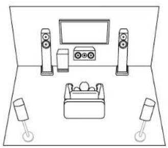
5.1 Channel System
This is a basic 5.1 Channel System.
Basic system (→p34)
natural_image
Line drawing of a room setup with speakers, TV, and storage unit (no text or symbols)5.1 ch + ZONE 2/ZONE 3 (→p34)

5.1 ch (Bi-Amping (Front/Center)) (→p34)

natural_image
Line drawing of a room setup with speakers, TV, and storage units (no text or symbols)




7.1 Channel System This is a 7.1 Channel System that consists of the basic 5.1 Channel System and added surround back speakers.
Basic system (→p34)

natural_image
Line drawing of a room setup with speakers, TV, and lighting fixtures (no text or symbols)7.1 ch + ZONE 2/ZONE 3 (→p34)
7.1 ch (Bi-Amping (Front/Center)) (→p34)

natural_image
Line drawing of a room setup with speakers, TV, and furniture (no text or symbols)7.1 ch (Bi-Amping (Front)) + ZONE 2 (→p34)






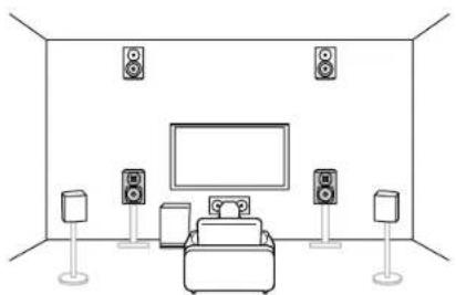
5.1.2 Channel System A Speaker System that is a 5.1 Channel System with one set of height speakers added.
5.1.2 ch (Front High or Rear High) (→p35)

natural_image
Line drawing of a modern living room with speakers, TV, and furniture (no text or symbols)5.1.2 ch (Top Front or Top Middle or Top Rear) (→p35)

natural_image
Line drawing of a person relaxing in a bathtub under ceiling lights (no text or symbols)5.1.2 ch (Dolby Enabled Speakers (Front or Surround)) (→p35)

natural_image
Line drawing of a room setup with speakers, TV, and a box (no text or symbols)5.1.2 ch + ZONE 2/ZONE 3 (→p35)

5.1.2 ch (Bi-Amping (Front)) (→p35)
natural_image
Line drawing of a room with a TV, speakers, and two smaller units (no text or symbols)




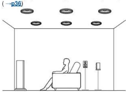
7.1.2 Channel System A Speaker System that is a 7.1 Channel System with one set of height speakers added.
7.1.2 ch (Front High or Rear High) (→p36)

natural_image
Line drawing of a modern audio setup with speakers, a TV, and a console (no text or symbols)7.1.2 ch (Top Front or Top Middle or Top Rear)
natural_image
Interior view of a room with ceiling lights, a person relaxing in the foreground, and a wall-mounted device (no text or symbols visible)7.1.2 ch (Dolby Enabled Speakers (Front or Surround or Surround Back)) (→p36)

natural_image
Line drawing of a room setup with speakers, TV, and a sofa (no text or symbols)7.1.2 ch + ZONE 2/ZONE 3 (→p36)

7.1.2 ch (Bi-Amping (Front)) (→p36)

natural_image
Line drawing of a modern living room with speakers, TV, and speakers on platforms (no text or symbols)





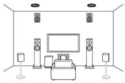
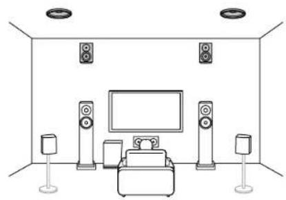
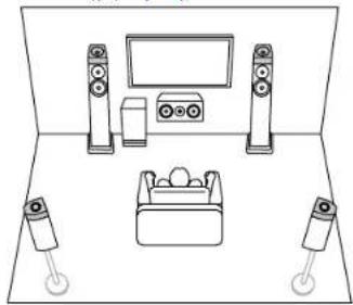
5.1.4 Channel System A Speaker System that is a 5.1 Channel System with two sets of height speakers added.
5.1.4 ch (Front High and Rear High) (→p37)

natural_image
Line drawing of a modern living room with speakers, TV, and furniture (no text or symbols)5.1.4 ch (Front High and Top Middle) (→p37)
natural_image
Line drawing of a modern living room with speakers, TV, and furniture (no text or symbols)5.1.4 ch (Front High and Top Rear) (→p37)
natural_image
Line drawing of a living room setup with TV, speakers, and speakers (no text or symbols)5.1.4 ch (Front High and Dolby Enabled Speakers (Surround)) (→p37)

natural_image
Line drawing of a room setup with speakers, TV, and a box (no text or symbols)5.1.4 ch (Top Front and Top Rear) (→p37)

natural_image
Line drawing of a person relaxing in a room with ceiling lights and a small TV stand (no text or symbols)5.1.4 ch (Top Front and Rear High) (→p37)

natural_image
Line drawing of a living room with TV, speakers, and ambient lighting (no text or symbols)





5.1.4 Channel System
Speaker Layout
5.1.4 ch (Top Front and Dolby Enabled Speakers (Surround)) (→p37)

natural_image
Line drawing of a room setup with speakers, monitors, and electronic devices (no text or symbols)5.1.4 ch (Top Middle and Rear High) (→p37)

natural_image
Line drawing of a living room setup with TV, speakers, and speakers (no text or symbols)5.1.4 ch (Dolby Enabled Speakers (Front and Surround)) (→p37)
natural_image
Line drawing of a room setup with speakers, TV, and a box (no text or symbols)5.1.4 ch (Dolby Enabled Speakers (Front) and Rear High) (→p37)

natural_image
Line drawing of a living room setup with speakers, TV, and furniture (no text or symbols)5.1.4 ch (Dolby Enabled Speakers (Front) and Top Rear) (→p37)

natural_image
Line drawing of a living room setup with speakers, TV, and furniture (no text or symbols)5.1.4 ch + ZONE 2/ZONE 3 (→p37)



5.1.4 Channel System
Speaker Layout
5.1.4 ch (Bi-Amping (Front)) (→p37)

natural_image
Line drawing of a modern living room with speakers, TV, and speakers (no text or symbols)





7.1.4 Channel System A Speaker System that is a 7.1 Channel System with two sets of height speakers added.
7.1.4 ch (Front High and Rear High) (→p38)

natural_image
Interior layout diagram of a room with speakers, a TV, and seating (no text or symbols)7.1.4 ch (Front High and Top Middle) (→p38)

natural_image
Line drawing of a room with speakers, a TV, and a sofa (no text or symbols)7.1.4 ch (Front High and Top Rear) (→p38)

natural_image
Line drawing of a room with a TV, speakers, and seating arrangement (no text or symbols)7.1.4 ch (Front High and Dolby Enabled Speakers (Surround)) (→p38)
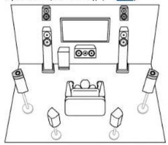
natural_image
Line drawing of a room setup with speakers, TV, and lighting fixtures (no text or symbols)7.1.4 ch (Front High and Dolby Enabled Speakers (Surround Back)) (→p38)
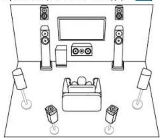
natural_image
Line drawing of a room setup with speakers, TV, and lighting fixtures (no text or symbols)7.1.4 ch (Top Front and Top Rear) (→p38)
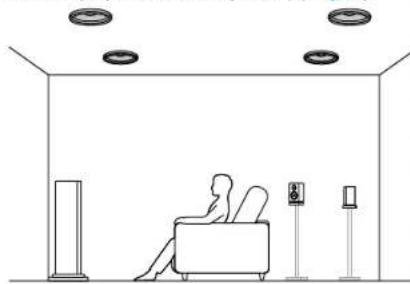
natural_image
Line drawing of a person relaxing in a living room with ceiling lights and a desk (no text or symbols)




7.1.4 Channel System
Speaker Layout
7.1.4 ch (Top Front and Rear High)

natural_image
Line drawing of a modern living room with speakers, TV, and seating (no text or symbols)7.1.4 ch (Top Front and Dolby Enabled Speakers (Surround)) (→p38)
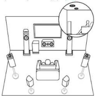
natural_image
Interior view of a home audio setup with speakers, headphones, and a monitor (no text or symbols visible)7.1.4 ch (Top Front and Dolby Enabled Speakers (Surround Back)) (→p38)
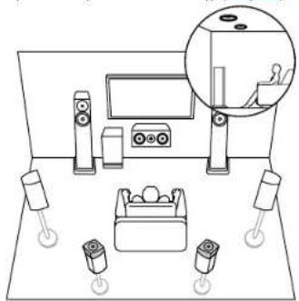
natural_image
Line drawing of a room setup with speakers, monitors, and lighting fixtures (no text or symbols)7.1.4 ch (Top Middle and Rear High) (→p38)

natural_image
Line drawing of a modern audio setup with speakers, a TV, and a console (no text or symbols)7.1.4 ch (Dolby Enabled Speakers (Front and Surround)) (→p38)

natural_image
Line drawing of a room setup with speakers, TV, and lighting fixtures (no text or symbols)7.1.4 ch (Dolby Enabled Speakers (Front and Surround Back)) (→p38)

natural_image
Line drawing of a room setup with speakers, TV, and lighting fixtures (no text or symbols)




7.1.4 Channel System
Speaker Layout
7.1.4 ch (Dolby Enabled Speakers (Front and Rear High) (→p38)

natural_image
Line drawing of a modern living room with speakers, TV, and speakers (no text or symbols)7.1.4 ch (Dolby Enabled Speakers (Front and Top Rear) (→p38)
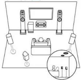
natural_image
Line drawing of a living room setup with speakers, TV, and furniture (no text or symbols)7.1.4 ch + ZONE 2/ZONE 3 (→p38)






Speaker Installation

Setting Up the Speakers
How the speakers are set up depends on the size and shape of the room, so here we introduce just a basic layout example.
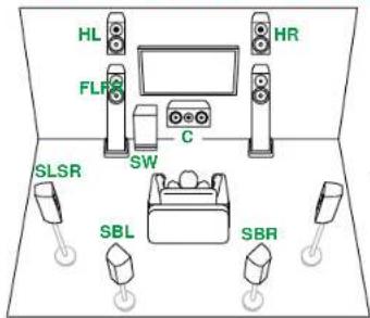
The alphabetic symbols used in this chapter represent the following speakers:
| FL Front speaker Left | |
| FR Front speaker Right | |
| C Center speaker | |
| SW powered SubWoofer | |
| SL Surround speaker Left | |
| SR Surround speaker Right | |
| SBL Surround Back speaker Left | |
| SBR Surround Back speaker Right | |
| FHL Front High speaker Left | |
| FHR Front High speaker Right | |
| RHL Rear High speaker Left | |
| RHR Rear High speaker Right | |
| TFL | Top Front speaker Left |
| TFR Top Front speaker Right | |
| TML Top Middle speaker Left | |
| TMR Top Middle speaker Right | |
| TRL | Top Rear speaker Left |
| TRR Top Rear speaker Right | |
| DFL Dolby enabled speaker Front Left | |
| DFR Dolby enabled speaker Front Right | |
| DSL Dolby enabled speaker Surround Left | |
| DSR Dolby enabled speaker Surround Right | |
| DSBL | Dolby enabled speaker Surround Back Left |
| DSBR | Dolby enabled speaker Surround Back Right |




5.1 Channel System
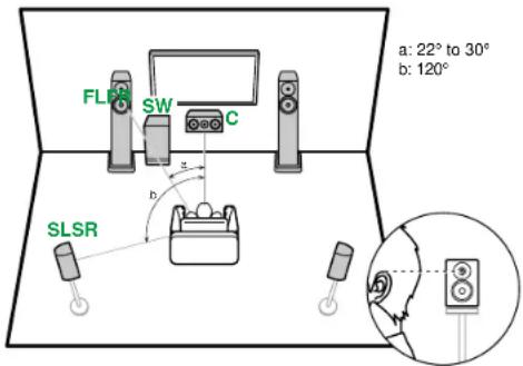
FL, FR Place the Left and Right Front Speakers to match ear height.
C The center speaker should be set up facing the listening position at an angle.
SW Place the powered subwoofer between the center speaker and a front speaker.
SL, SR Place the Left and Right Surround Speakers to be just above ear height.
■ 5.1 ch connection (→p42)
■ 5.1 ch + ZONE 2/ZONE 3 connection (→p43)
■ 5.1 ch (Bi-Amping (Front/Center)) connection (→p44)
■ 5.1 ch connection (→p42)
■ 5.1 ch + ZONE 2/ZONE 3 connection (→p43)
■ 5.1 ch (Bi-Amping (Front/Center)) connection (→p44)




Speaker Installation
7.1 Channel System
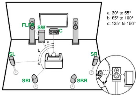
FL, FR Place the Left and Right Front Speakers to match ear height.
C The center speaker should be set up facing the listening position at an angle.
SW Place the powered subwoofer between the center speaker and a front speaker.
SL, SR Place the Left and Right Surround Speakers to be just above ear height.
SBL, SBR Place the Left and Right Surround Back Speakers at ear height. If surround back speakers are installed, be sure to install surround speakers as well.
■ 7.1 ch connection (→p45)
■ 7.1 ch + ZONE 2/ZONE 3 connection (→p46)
■ 7.1 ch (Bi-Amping (Front/Center)) connection (→p47)
■ 7.1 ch (Bi-Amping (Front)) + ZONE 2 connection (→p48)



5.1.2 Channel System
High Speakers
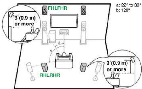
FHL, FHR Place the front high speakers directly above the front speakers, angled to face the listening position.
RHL, RHR Place the rear high speakers so the lateral distance matches the front speakers, angled to face the listening position.
■ 5.1.2 ch connection (→p49)
■ 5.1.2 ch + ZONE 2/ZONE 3 connection (→p50)
■ 5.1.2 ch (Bi-Amping (Front)) connection (→p51)
■ 5.1.2 ch connection (→p49)
■ 5.1.2 ch + ZONE 2/ZONE 3 connection (→p50)
■ 5.1.2 ch (Bi-Amping (Front)) connection (→p51)
7.1.2 Channel System
High Speakers
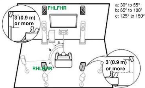
FHL, FHR Place the front high speakers directly above the front speakers, angled to face the listening position.
RHL, RHR Place the rear high speakers so the lateral distance matches the front speakers, angled to face the listening position.
■ 7.1.2 ch connection (→p52)
■ 7.1.2 ch + ZONE 2 connection (→p53)
■ 7.1.2 ch + ZONE 2/ZONE 3 connection (→p54)
■ 7.1.2 ch (Bi-Amping (Front)) connection (→p55)
■ 7.1.2 ch connection (→p52)
■ 7.1.2 ch + ZONE 2 connection (→p53)
■ 7.1.2 ch + ZONE 2/ZONE 3 connection (→p54)
■ 7.1.2 ch (Bi-Amping (Front)) connection (→p55)



Speaker Installation
Top Speakers

TFL, TFR Fit top front speakers on the ceiling in front of the listening position.
TML, TMR Fit top middle speakers on the ceiling directly above the listening position.
TRL, TRR Fit top rear speakers on the ceiling behind the listening position.
- Match the lateral distance of the top speakers to the front speakers.
Dolby Enabled Speakers
flowchart
graph TD
    DSL["DSL"] -->|a| TV["TV"]
    DSR["DSR"] -->|b| TV
    DSB["DSBL"] -->|c| TV
    DFR["DFR"] -->|a| TV
    DFL["DFL"] -->|b| TV
    TV --> Display["Monitor"]
    Display --> Display
    Display --> Tablet["Screen"]
    Tablet --> Display
    Display --> Desktop["DBR"]
a: 30^ to 55^
b: 65° to 100°
c: 125° to 150°
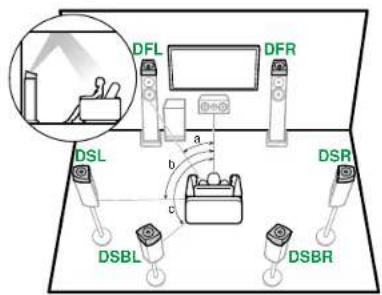
DFL, DFR The Dolby enabled speakers (front) are installed on top of the front speakers.
DSL, DSR The Dolby enabled speakers (surround) are installed on top of the surround speakers.
DSBL, DSBR The Dolby enabled speakers (surround back) are installed on top of the surround back speakers.


5.1.4 Channel System
High Speakers

FHL, FHR Place the front high speakers directly above the front speakers, angled to face the listening position.
RHL, RHR Place the rear high speakers so the lateral distance matches the front speakers, angled to face the listening position.
■ 5.1.4 ch connection (→p56)
■ 5.1.4 ch + ZONE 2/ZONE 3 connection (→p57)
■ 5.1.4 ch (Bi-Amping (Front)) connection (→p58)
■ 5.1.4 ch connection (→p56)
■ 5.1.4 ch + ZONE 2/ZONE 3 connection (→p57)
■ 5.1.4 ch (Bi-Amping (Front)) connection (→p58)
7.1.4 Channel System
High Speakers

FHL, FHR Place the front high speakers directly above the front speakers, angled to face the listening position.
RHL, RHR Place the rear high speakers so the lateral distance matches the front speakers, angled to face the listening position.
■ 7.1.4 ch connection (→p59)
■ 7.1.4 ch + ZONE 2/ZONE 3 connection (→p60)
■ 7.1.4 ch connection (→p59)
■ 7.1.4 ch + ZONE 2/ZONE 3 connection (→p60)



Speaker Installation
Top Speakers

TFL, TFR Fit top front speakers on the ceiling in front of the listening position.
TML, TMR Fit top middle speakers on the ceiling directly above the listening position.
TRL, TRR Fit top rear speakers on the ceiling behind the listening position.
- Match the lateral distance of the top speakers to the front speakers.
Dolby Enabled Speakers

flowchart
graph TD
    DSL["DSL"] -->|a| PC["PC"]
    DSR["DSR"] -->|b| PC
    DSB["DSBL"] -->|c| PC
    DFR["DFR"] -->|a| PC
    DFL["DFL"] -->|b| PC
    style DSL fill:#f9f,stroke:#333
    style DSR fill:#f9f,stroke:#333
    style DSB fill:#f9f,stroke:#333
    style DFR fill:#f9f,stroke:#333
    style DFL fill:#ccf,stroke:#333
    style DSR fill:#ccf,stroke:#333
    style DSB fill:#ccf,stroke:#333
    style DFR fill:#ccf,stroke:#333
a: 30^ to 55^
b: 65° to 100°
c: 125° to 150°
DFL, DFR The Dolby enabled speakers (front) are installed on top of the front speakers.
DSL, DSR The Dolby enabled speakers (surround) are installed on top of the surround speakers.
DSBL, DSBR The Dolby enabled speakers (surround back) are installed on top of the surround back speakers.


Speaker Connections
(Before starting the procedure)
Speakers you can use with this unit and cable connections
40

Connect the Subwoofer 41
5.1 Channel System 42, 43, 44
7.1 Channel System 45, 46, 47, 48
5.1.2 Channel System 49, 50, 51
7.1.2 Channel System 52, 53, 54, 55
5.1.4 Channel System 56, 57, 58
7.1.4 Channel System 59, 60
Connecting a Power Amplifier 61





Speakers you can use with this unit and cable connections
■ Speakers you can use with this unit
This unit supports speakers with 4 Ω to 16 Ω impedance. For speaker impedance, check the speaker instruction manual.
■ (Note) Speaker Impedance
If any of the speakers to be connected has an impedance of 4 Ω or more and less than 6 Ω, set "Speaker Impedance" to "4ohms" for "Speaker Setup" in the Initial Setup section (→p175). When setting "Speaker Impedance" from the System Setup menu, press the 🔒 button on the remote controller to display the Home screen, and select "System Setup" - "Speaker" - "Configuration", then set "Speaker Impedance" (→p136) to "4ohms".
■ Connect the Speaker Cables

Make correct connection between the unit's jacks and speaker's jacks (+ side to + side, and - side to - side) for each channel. If the connection is wrong, a bass sound will not be reproduced properly due to reverse phase. Twist the wires exposed from the tip of the speaker cable so that the wires do not stick out of the speaker terminal when connecting. If the exposed wires touch the rear panel, or the + side and - side wires touch each other, a malfunction may occur.

natural_image
Illustration of a red fuse with black leads emitting lightning bolts, accompanied by a no-sho symbol (no text or labels)


Connect the Subwoofer
Speaker Connections

Connect a powered subwoofer with this unit using a subwoofer cable.
- Up to four powered subwoofers can be connected.
- Different signals are output from the SW1 and SW2 terminals. The volume level can also be set separately. (→p140)
- The same signals are output from "A" and "B" of the SW1 terminal. The SW2 terminal also has the same specification.
a Subwoofer cable







Speaker Connections
5.1 Channel System






Speaker Connections
5.1 Channel System + ZONE SPEAKER (ZONE 2/ZONE 3)
MAIN ROOM

ZONE 2

ZONE 3

- Playing Back (ZONE 2) (→p109)
- Playing Back (ZONE 3) (→p111)






Speaker Connections
■ 5.1 Channel System (Bi-Amping the Speakers)

Be sure to remove the jumper bar connecting between the woofer jacks and tweeter jacks of the Bi-Amping supported speakers. Refer to the instruction manual of your speakers as well.



Speaker Connections
7.1 Channel System





Speaker Connections
7.1 Channel System + ZONE SPEAKER (ZONE 2/ZONE 3)
MAIN ROOM
ZONE 2

ZONE 3

- Playing Back (ZONE 2) (→p109)
- Playing Back (ZONE 3) (→p111)

- Surround back speakers need to be connected to the HEIGHT 1 jacks.



Speaker Connections
7.1 Channel System (Bi-Amping the Speakers)

Be sure to remove the jumper bar connecting between the woofer jacks and tweeter jacks of the Bi-Amping supported speakers. Refer to the instruction manual of your speakers as well.



7.1 Channel System (Bi-Amping the Speakers)+ZONE SPEAKER (ZONE 2)
MAIN ROOM

ZONE 2
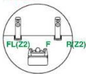
- Playing Back (ZONE 2) (→p109)

Be sure to remove the jumper bar connecting between the woofer jacks and tweeter jacks of the Bi-Amping supported speakers. Refer to the instruction manual of your speakers as well.
- Surround back speakers need to be connected to the HEIGHT 2 jacks.






Speaker Connections
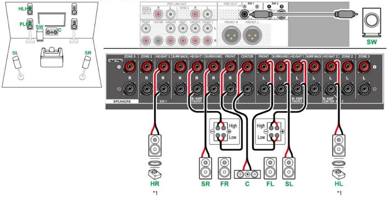
5.1.2 Channel System

*1 Connect the Height Speakers you have actually installed (HL/HR: Height Speakers, Top Speakers, Dolby Enabled Speakers).






Speaker Connections
5.1.2 Channel System + ZONE SPEAKER (ZONE 2/ZONE 3)
MAIN ROOM

ZONE 2

ZONE 3
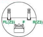
- Playing Back (ZONE 2) (→p109)
- Playing Back (ZONE 3) (→p111)

*1 Connect the Height Speakers you have actually installed (HL/HR: Height Speakers, Top Speakers, Dolby Enabled Speakers).






Speaker Connections
■ 5.1.2 Channel System (Bi-Amping the Speakers)
Be sure to remove the jumper bar connecting between the woofer jacks and tweeter jacks of the Bi-Amping supported speakers. Refer to the instruction manual of your speakers as well.
*1 Connect the Height Speakers you have actually installed (HL/HR: Height Speakers, Top Speakers, Dolby Enabled Speakers).





Speaker Connections
7.1.2 Channel System

*1 Connect the Height Speakers you have actually installed (HL/HR: Height Speakers, Top Speakers, Dolby Enabled Speakers).






Speaker Connections
7.1.2 Channel System + ZONE SPEAKER (ZONE 2)
MAIN ROOM

ZONE 2
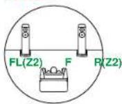
- Playing Back (ZONE 2) (→p109)
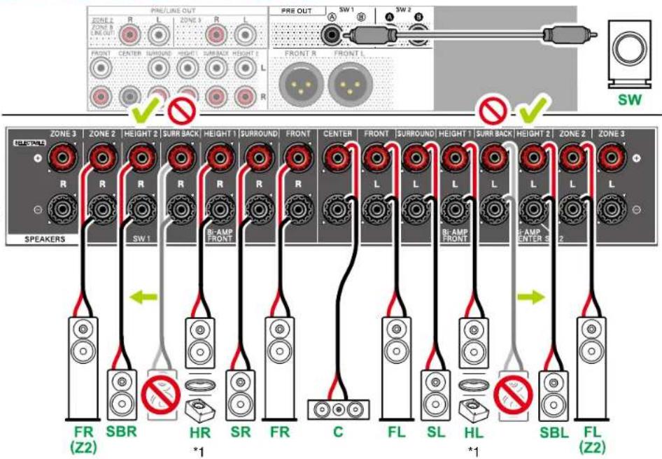
- Surround back speakers need to be connected to the HEIGHT 2 jacks.
*1 Connect the Height Speakers you have actually installed (HL/HR: Height Speakers, Top Speakers, Dolby Enabled Speakers).





Speaker Connections
7.1.2 Channel System + ZONE SPEAKER (ZONE 2/ZONE 3)
MAIN ROOM

ZONE 2

ZONE 3

- Playing Back (ZONE 2) (→p109)
- Playing Back (ZONE 3) (→p111)

- While ZONE 2/ZONE 3 playback is being performed, surround back speakers installed in the main room cannot play audio.
*1 Connect the Height Speakers you have actually installed (HL/HR: Height Speakers, Top Speakers, Dolby Enabled Speakers).



Speaker Connections
7.1.2 Channel System (Bi-Amping the Speakers)

Be sure to remove the jumper bar connecting between the woofer jacks and tweeter jacks of the Bi-Amping supported speakers. Refer to the instruction manual of your speakers as well.
*1 Connect the Height Speakers you have actually installed (HL/HR: Height Speakers, Top Speakers, Dolby Enabled Speakers).




Speaker Connections
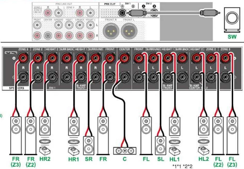
5.1.4 Channel System

*1 Connect the Height Speakers you have actually installed (HL1/HR1: Front Height Speakers, Top (front side) Speakers, Dolby Enabled Speakers (Front)).
*2 Connect the Height Speakers you have actually installed (HL2/HR2: Rear Height Speakers, Top (rear side) Speakers, Dolby Enabled Speakers (Surround)).





Speaker Connections
5.1.4 Channel System + ZONE SPEAKER (ZONE 2/ZONE 3)
MAIN ROOM

ZONE 2

ZONE 3
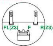
- Playing Back (ZONE 2) (→p109)
- Playing Back (ZONE 3) (→p111)
- While ZONE 2/ZONE 3 playback is being performed, height 2 speakers installed in the main room cannot play audio.
*1 Connect the Height Speakers you have actually installed (HL1/HR1: Front Height Speakers, Top (front side) Speakers, Dolby Enabled Speakers (Front)).
*2 Connect the Height Speakers you have actually installed (HL2/HR2: Rear Height Speakers, Top (rear side) Speakers, Dolby Enabled Speakers (Surround)).






Speaker Connections
■ 5.1.4 Channel System (Bi-Amping the Speakers)

Be sure to remove the jumper bar connecting between the woofer jacks and tweeter jacks of the Bi-Amping supported speakers. Refer to the instruction manual of your speakers as well.
*1 Connect the Height Speakers you have actually installed (HL1/HR1: Front Height Speakers, Top (front side) Speakers, Dolby Enabled Speakers (Front)).
*2 Connect the Height Speakers you have actually installed (HL2/HR2: Rear Height Speakers, Top (rear side) Speakers, Dolby Enabled Speakers (Surround)).





Speaker Connections
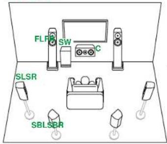
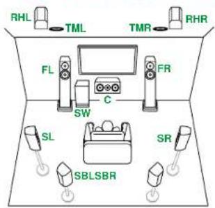
7.1.4 Channel System
flowchart
graph TD
    RHL --> TML
    TML --> TMR
    TMR --> RHR
    FL --> SW
    FR --> C
    SL --> SBLSBR
    SR --> SBLSBR
    SW --> C
    C --> FR

*1 Connect the Height Speakers you have actually installed (HL1/HR1: Front Height Speakers, Top (front side) Speakers, Dolby Enabled Speakers (Front)).
*2 Connect the Height Speakers you have actually installed (HL2/HR2: Rear Height Speakers, Top (rear side) Speakers, Dolby Enabled Speakers (Surround, Surround Back)).




Speaker Connections
7.1.4 Channel System + ZONE SPEAKER (ZONE 2/ZONE 3)
MAIN ROOM

ZONE 2
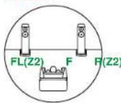
ZONE 3

- Playing Back (ZONE 2) (→p109)
- Playing Back (ZONE 3) (→p111)
- Playing Back (ZONE 2) (→p109)
- Playing Back (ZONE 3) (→p111)


- While ZONE 2 playback is being performed, surround back speakers installed in the main room cannot play audio.
- While ZONE 2/ZONE 3 playback is being performed, surround back speakers and height 2 speakers installed in the main room cannot play audio.
*1 Connect the Height Speakers you have actually installed (HL1/HR1: Front Height Speakers, Top (front side) Speakers, Dolby Enabled Speakers (Front)).
*2 Connect the Height Speakers you have actually installed (HL2/HR2: Rear Height Speakers, Top (rear side) Speakers, Dolby Enabled Speakers (Surround, Surround Back)).





Connecting a Power Amplifier
Speaker Connections

Power amplifier
You can connect a power amplifier to the unit and use the unit as a pre-amplifier. Use an analog audio cable or XLR balanced cable for connection.
- Also make sure you read the instruction manual supplied with the connected power amplifier.
- For details on how to connect the speakers and the power amplifier, refer to the instruction manual of the power amplifier.

Setup
- Set "System Setup" - "Speaker" - "Configuration" - "Speaker Channels" (→p134) in accordance to the number of channels for the connected speakers
a Analog audio cable, b XLR balanced cable







Connections

Notes regarding connections with HDMI cables 63
Connecting the TV 64
Connecting the SUB Monitor 66
Connecting Playback Devices 67
Connecting a TV or Integrated Amplifier in a separate room (Multi-zone) 71
Connecting Antennas (North American and Taiwanese models) 74
Network Connection 75
Connecting External Control Devices 76
Connecting the Power Cord 78






Notes regarding connections with HDMI cables
HDMI (High-Definition Multimedia Interface) is a digital interface standard for connecting TVs, projectors, Blu-ray Disc players, game consoles, and other video components. With HDMI, a single cable can carry control signals, digital video, and digital audio.
Connections
Push HDMI cables straight in and all the way. You can damage the terminals if you try to insert at an angle.
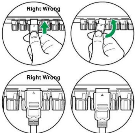
- Hold the terminal housing on the HDMI cable when unplugging. Pulling on the cable may lead to damaged cabling.
■ (Note) Placement of cables
Putting a load on HDMI cables can lead to poor operational performance. Place the cables so there is no load put on them.

natural_image
Three circular diagrams showing electrical connections with plug and socket, no text or symbols presentRight Wrong Wrong
- When 4K high-quality video (4K 120Hz, etc.) or 8K high-quality video (8K 60Hz, etc.) is to be played, use ULTRA High Speed HDMI Cable that has the "ULTRA HIGH SPEED" label attached to the packaging.






Connecting the TV
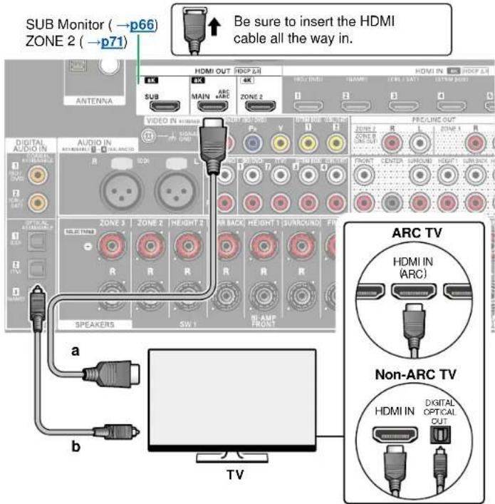
By connecting a TV to this unit, you can show the video from AV devices connected to this unit on the TV and also play the sound from the TV through this unit.
To ARC/eARC TV
If the TV supports the ARC (Audio Return Channel) function(*), use only the HDMI cable to connect with the TV. Use the ARC-compatible HDMI IN jack of the TV for connection. You connect the HDMI cable to the HDMI OUT MAIN jack labeled "ARC" on the receiver side.
- When a TV compatible with the eARC function is connected, use an HDMI cable that supports Ethernet.
To Non-ARC TV
If the TV does not support the ARC (Audio Return Channel) function(*), connect an HDMI cable and digital optical cable. If the TV does not have a DIGITAL OPTICAL OUT jack, you can use an analog audio cable to connect with the AUDIO IN TV jack.
- If you use a cable set-top box, etc. connected to the input jack of this unit to watch TV (without using a TV's built-in tuner), connection with a digital optical cable or analog audio cable is not required.

Setup
- When not using the ARC function, in the Home screen, set "System Setup" - "Hardware" - "HDMI" - "Audio Return Channel (eARC supported)" (→p147) to "Off".
(*)The ARC function and eARC function transmit the audio signals of the TV via an HDMI cable, and plays the audio of the TV on this unit. To check if the TV supports the ARC function and eARC function, refer to the instruction manual of the TV, etc.
ARC/eARC compatible audio formats (→p216)
a HDMI cable, b Digital optical cable



Connections
- Settings are required when 8K high-quality video is to be played. Refer to "HDMI 4K/8K Signal Format" (→p129) for information on the settings. Also, use an HDMI cable that supports 8K video.






Connecting the SUB Monitor

SUB Monitor
This unit has multiple HDMI OUT jacks, and another TV or projector can be connected to the HDMI OUT SUB jack.
- Switch between MAIN and SUB using the HDMI MAIN/SUB button on the remote controller (→p18) or "AV Adjust" (→p91). Note that this jack is not ARC-compatible.
- If devices with different resolutions are connected to HDMI OUT MAIN jack and SUB jack, images are output with the lower resolution.
a HDMI cable






Connecting Playback Devices
Connections to BD/DVD and GAME with HDMI jacks

This is a connection example of an AV component equipped with an HDMI jack. When connecting with an AV component that conforms to the CEC (Consumer Electronics Control) standard, you can use the HDMI CEC function (*) that enables linking with input selectors, etc. and the HDMI Standby Through function that can transmit video and audio signals of the AV component to the TV even if this unit is in standby mode.
- Settings are required when 8K high-quality video is to be played. Refer to "HDMI 4K/8K Signal Format" (→p129) for information on the settings. Also, use an HDMI cable that supports 8K video.
- The corresponding resolution is different depending on the HDMI jack connected. See "Corresponding input resolutions" (→p217) for details.
Note
- To enjoy digital surround sound including Dolby Digital, set the audio output of the connected Blu-ray Disc player etc. to the Bitstream output.
(*)The HDMI CEC function: This function enables various linking operations with CEC-compliant devices, such as switching input selectors interlocking with a CEC-compliant player, switching audio output between TV and this unit or adjusting the volume using the remote controller of a CEC-compliant TV, and automatically switching this unit to standby when the TV is turned off.
a HDMI cable




Connecting a BD/DVD without HDMI Jack Mounted

This is a connection example of an AV component unequipped with an HDMI jack. Select cables that match the jacks of the AV component for connection. For example, when video input is connected to the BD/DVD jack, connect the audio input to BD/DVD jack, too. Thus, video input jacks and audio input jacks should have the same name for connection. Note that video signals input to the VIDEO IN jack or the COMPONENT VIDEO IN jack are converted to HDMI video signals, and then output from the HDMI OUT jack.
- To enjoy digital surround playback in formats such as Dolby Digital, you need to make a connection for audio signals with a digital coaxial cable or a digital optical cable.
- According to the illustration, changing the input assignment (→p130) enables connection to jacks other than the BD/DVD jack.
Note
- The COMPONENT VIDEO IN jacks are compatible only with 480i or 576i resolution. When connecting to the COMPONENT VIDEO IN jacks, set the output resolution of the player to 480i or 576i. If there is no option such as 480i, select interlace. If your player does not support 480i or 576i output, use the VIDEO IN jack.
- To enjoy digital surround sound including Dolby Digital, set the audio output of the connected Blu-ray Disc player etc. to the Bitstream output.
a Digital coaxial cable, b Analog audio cable, c Component video cable






Connecting an Audio Component

This is a connection example of an audio component. Connect a CD player using an XLR balanced cable or digital optical cable. You can also connect a turntable that has an MM-type cartridge to the PHONO jack.
- If the turntable has a built-in phono equalizer, connect it to any of the AUDIO IN jacks other than the PHONO jack. Further, if the turntable uses an MC type cartridge, install a phono equalizer compatible with the MC type cartridge between the unit and the turntable, and then connect it to any of the AUDIO IN jacks other than the PHONO jack.

If the turntable has a ground wire, connect it to the SIGNAL GND terminal of this unit.
a XLR balanced cable, b Digital optical cable, c Analog audio cable


Connecting a Video Camera, etc.
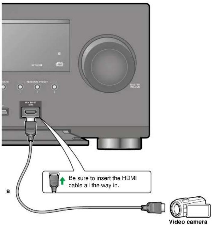
Connect a video camera, etc. to the AUX INPUT HDMI jack on the front panel using an HDMI cable.
a HDMI cable


Connecting a TV or Integrated Amplifier in a separate room (Multi-zone)
Connecting a TV (ZONE 2)
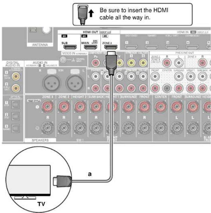
a HDMI cable




While a disc is played on a Blu-ray Disc player in the main room (where this unit is located), you can play the video and audio of the same Blu-ray Disc player or another AV component on the TV equipped with an HDMI IN jack in a separate room (ZONE 2).
- The audio from externally connected AV components can be output only when the signal is 2 ch PCM audio. It may also be necessary to convert the audio output of the AV component to PCM output.

Setup
- When video and audio via HDMI input are output to ZONE 2, set "Input/Output Assign" - "TV Out / OSD" - "Zone 2 HDMI" (→p129) to "Use" on the System Setup menu. Note that when "Zone 2 HDMI" is set to "Use", the resolution of the video that can be output by the HDMI OUT ZONE 2 jack will be limited to "4K Enhanced" (→p129).
□ Multi-zone ( →p108)
□ Playing Back (ZONE 2) (→p109)



Connecting an Integrated Amplifier (ZONE 2)

You can enjoy 2 ch audio in the separate room (ZONE 2) while performing playback in the main room (where this unit is located). Use an analog audio cable to connect the ZONE 2 PRE/LINE OUT jack on this unit to the input jack on an integrated amplifier in the separate room.
- If the AV component is not equipped with an HDMI jack, use a digital coaxial cable, digital optical cable or analog audio cable. Also, the audio from externally connected AV components can be output to ZONE 2 only when the audio is analog or 2 ch PCM signal. When the AV component is connected to this unit with a digital coaxial cable or digital optical cable, change the audio output of the AV component to the PCM output.

Setup
- Settings are required to output audio to ZONE 2. Press on the remote controller to display the Home screen, then set "System Setup" - "Speaker" - "Configuration" - "Zone 2 Preout" (→p136) to "Zone 2".
- When connecting an integrated amplifier that does not have a volume control, in the System Setup, set "Multi Zone" - "Zone 2" - "Output Level" (→p152) to "Variable (Default Value : Fixed)". If you do not set this, the volume output will be very loud and there is a danger of damage to the integrated amplifier, speakers, etc. When connecting an integrated amplifier that has a volume control, leave this as "Fixed".
a Analog audio cable




□ Multi-zone ( →p108)
□ Playing Back (ZONE 2) (→p109)


Connecting an Integrated Amplifier (ZONE 3)

You can enjoy 2 ch audio in the separate room (ZONE 3) while performing playback in the main room (where this unit is located). Use an analog audio cable to connect the ZONE 3 PRE/LINE OUT jack on this unit to the input jack on an integrated amplifier in the separate room. The same source can be played back in the main room and ZONE 3 simultaneously. Also, different sources can be played back in both rooms.
- To output audio from an externally connected AV component to ZONE 3, use an analog audio cable for connection. Note that ZONE 3 output is not possible with the connection using a HDMI cable, digital coaxial cable, or digital optical cable.

Setup
- With speaker combinations "Speaker combinations" (→p212) 2.1.2 ch, 3.1.2 ch, 4.1.2 ch, or 5.1.2 ch, this function cannot be used when using Bi-AMP or ZONE 2 (ZONE SPEAKER). However, when a power amplifier is connected to the ZONE 3 PRE/LINE OUT jacks, it is possible to use ZONE 2 (ZONE SPEAKER) and ZONE 3 (ZONE SPEAKER). - When connecting an Integrated Amplifier that has an external volume control, set "Multi Zone" - "Zone 3" - "Output Level" (→p153) to "Fixed (Default Value)" on the System Setup. If your external Integrated Amplifier does not have an external volume control please set this at "Variable". If you do not set this, the volume output will be very loud and there is a danger of damage to the integrated amplifier, speakers, etc.
Note
- ZONE 3 PRE/LINE OUT cannot be used when the connected speaker configuration is "6.1 ch", "7.1 ch", "6.1.2 ch", "7.1.2 ch", "4.1.4 ch", "5.1.4 ch", "6.1.4 ch", or "7.1.4 ch".
a Analog audio cable




□ Multi-zone (→p108)
□ Playing Back (ZONE 3) (→p111)



Connecting Antennas (North American and Taiwanese models)
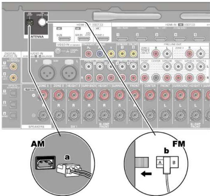
Connect the antenna to this unit, and set up the antenna at the best position for listening while receiving radio signals. Attach the indoor FM antenna to the wall using push pins or adhesive tape.
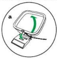

a AM loop antenna, b Indoor FM antenna






Network Connection
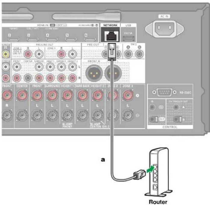
This unit can be connected to the network using a wired LAN or Wi-Fi (wireless LAN). You can enjoy network functions such as Internet radio by network connection. If connection is made by the wired LAN, connect the router and the NETWORK jack with the Ethernet cable as shown in the illustration. To connect by Wi-Fi, select your desired setting method in "Network Connection" (→p176) of Initial Setup, and then follow the on-screen instructions. To set in the System Setup menu after completing Initial Setup, press on the remote controller, then from the Home screen displayed, set in "Network/Bluetooth" - "Network" (→p168). For the Wi-Fi connection, stand the wireless antenna for use.
Note
- For security reasons, always connect via a router, etc., when connecting this unit to the Internet. Do not directly connect to the communication circuits (including public wireless LAN) of a telecommunications provider (mobile communications company, fixed-line communications company, Internet provider, etc.).
a Ethernet cable






Connecting External Control Devices
IR IN/OUT port

When connecting a remote control receiver unit consisting of an IR Receiver, etc. to this unit, operation using the remote controller is possible even if the remote control signal is difficult to reach (due to installation in the cabinet, etc.). It is also possible to operate this unit from other room such as ZONE 2 with a remote controller, or operate other devices with the remote controller by connecting other devices to this unit. For installing a remote control receiver unit, contact the specialized stores.
- For the type of cable required for connection, refer to the operation manual, etc. of the remote control receiver unit.




12V TRIGGER OUT jack
Connections

BD/DVD
When connecting a device equipped with a 12V TRIGGER IN jack such as a BD/DVD player to this unit, the device can be turned on or set to standby by interlocking the operation on this unit. When the desired input is selected on the unit, power link operation will be activated with a control signal of maximum 12 V/100 mA from the 12V TRIGGER OUT A jack or maximum 12 V/25 mA when using the 12V TRIGGER OUT B jack. You can select the zone to output the control signal by setting each of the inputs.
- For connection, use a monaural mini plug cable (ø1/8" / 3.5 mm) without resistance. Do not use a stereo mini plug cable.

Setup
- Settings are required to outputs control signal from the 12V TRIGGER OUT jack. Press on the remote controller then from the displayed Home screen set the input select for "System Setup" - "Hardware" - "12V Trigger A" (→p150) or "12V Trigger B" (→p150) to "Main", "Zone 2", or "Zone 3".
a Monaural mini plug cable (ø1/8" / 3.5 mm)




Connecting the Power Cord
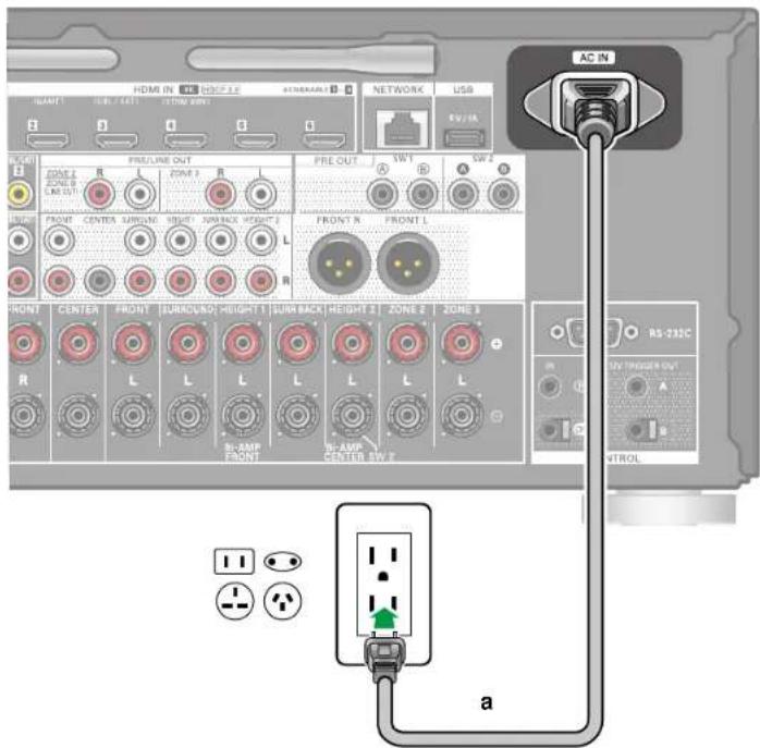
Connect the power cord after all the connections are completed.
- This unit includes a removable power cord. Be sure to connect the power cord to the AC IN of the unit first, and then connect it to the outlet. Always disconnect the outlet side first when disconnecting the power cord.
a Power cord


Playback
Basic Operations
| Basic Operations 80 | |
| Listening Mode 83 | |
| BLUETOOTH®Playback 84 | |
| Listening To the Radio (North American and Taiwanese models) | 88 |
| AV Adjust | 91 |
Network Services
| Spotify | 95 |
| AirPlay® | 96 |
| DTS Play-Fi® | 98 |
| Amazon Alexa 99 | |
| Amazon Music 101 | |
| TIDAL | 103 |
| Connecting the Sonos System for Playback 104 | |
| Internet Radio 106 | |
Convenience functions
| Multi-zone | 108 |
| Using PERSONAL PRESET 113 | |
| AV Direct Mode | 115 |
| Playing music files saved on a USB storage device | 116 |
| Music Server 118 | |
| Play Queue | 121 |
| Connecting a transmitter for playback | 123 |



Basic Operations
Turning the power on
- Press "O" on the remote controller to turn on the power of the unit.
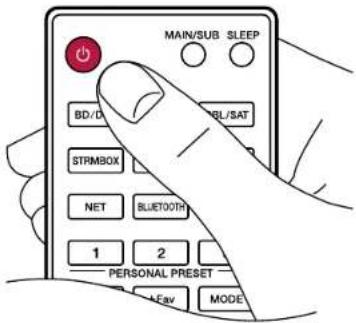
You can also turn on the power of the unit with the following operations:
- Pressing " on the main unit.
- Using the Pioneer Remote App (→p181) app
- Using the linking function (HDMI CEC) (→p81)
Selecting a source to play
- Press an input selector button on the remote controller to select a source. For example, to play the device connected to the BD/DVD jack, press the BD/DVD button. To listen to the audio of the TV, press TV button.

You can also select a source to play with the following operations:
- Pressing an input selector button on the main unit
- Using the Pioneer Remote App (→p181) app






Adjusting the volume
- Press the VOLUME buttons on the remote controller to adjust the volume. To temporarily turn off the sound, press the ⓄMUTE button. Press again to cancel.
- When Dolby Vision images are received, the volume bar on the TV screen changes from blue to magenta.

You can also adjust the volume with the following operations:
- Using the MASTER VOLUME on the main unit
- Using the Pioneer Remote App (→p181) app
- Using the linking function (HDMI CEC) (→p81)




Playback
Using the linking function (HDMI CEC)
By using a HDMI cable and connecting to a TV that is compatible with the HDMI CEC (Consumer Electronics Control) function, you are able to perform operations such as adjusting the volume of this unit with the TV's remote controller and link power On/Off. Furthermore, if you have connected a Blu-ray Disc player, GAME, etc. that is compatible with the HDMI CEC function, input switching is performed automatically.
- HDMI CEC settings ( →p146) (the default value is "On")
- For information about the HDMI CEC functions of the TV, refer to the operating instructions, etc., for the TV.
- The unit is designed to link with products that comply with the CEC standard, and that linked operation is not always guaranteed with all CEC devices.
- For linked functions to work properly, do not connect CEC-compliant devices exceeding the connectable number to the HDMI jack as shown below.
- Blu-ray Disc/DVD players: up to 3 units
- Blu-ray Disc/DVD recorders: up to 3 units
– Cable TV tuner, terrestrial digital tuner, and satellite broadcasting tuner: up to 4 units


Switching the display
Repeatedly pressing the button on the remote controller switches the display of the main unit in the following order.
- The content displayed depends on the source, BLUETOOTH, etc., being played.
- Depending on the audio signal, "B(Back)" or "W (Wide)" is displayed next to the number of channels of the input format.
- Not all the information is necessarily displayed.

flowchart
graph TD
    A["Listening mode"] --> B["DTS Neural : X"]
    B --> C["Input format"]
    C --> D["DTS-HDMSTR 5.1"]
    D --> E["Sampling frequency"]
    E --> F["176.4 kHz"]
    F --> G["Input signal resolution"]
    G --> H["1080 p/59 16:9"]
    H --> I["Input source and volume"]
    I --> J["BD/DVD 40.0"]
    J --> K["IP Address"]
    K --> L["192168 XXXX"]





Listening Mode
The listening mode can be switched by pressing the "AUTO/DIRECT",
"SURROUND", and "STEREO" buttons repeatedly during play.
- For details of the effects of each listening mode, refer to "Listening Mode Effects" (→p207).
- For listening modes selectable for each audio format of input signals, refer to "Input Formats and Selectable Listening Modes" (→p203).
Selecting a Listening mode
- Press one from among AUTO/DIRECT, SURROUND, and STEREO during playback.

- Press the selected button repeatedly to switch the modes displayed on the display of the main unit.
DTS
- Each of AUTO/DIRECT, SURROUND, and STEREO buttons stores the listening mode that was selected last. If content incompatible of the listening mode selected last is played, the most standard listening mode for the content is automatically selected.
Dolby Atmos


Manufactured under license from Dolby Laboratories. Dolby, Dolby Vision, Dolby Atmos, Dolby Audio, and the double-D symbol are trademarks of Dolby Laboratories.
For DTS patents, see http://patents.dts.com. Manufactured under license from DTS, Inc. or under license from DTS Licensing Limited. DTS, DTS:X, DTS Play-Fi, Play-Fi and the DTS:X, DTS Play-Fi, and Play-Fi logos are registered trademarks or trademarks of DTS, Inc. and its affiliates in the United States and other countries. © 2022 DTS, Inc. ALL RIGHTS RESERVED.
Manufactured under license from IMAX Corporation. IMAX® is a registered trademark of IMAX Corporation in the United States and/or other countries. For DTS patents, see http://patents.dts.com. Manufactured under license from DTS, Inc. DTS and the DTS logo are registered trademarks or trademarks of DTS, Inc. in the United States and other countries. © 2020 DTS, Inc. ALL RIGHTS RESERVED.







BLUETOOTH® Playback
You can wirelessly play music on a smartphone or other BLUETOOTH wireless technology enabled device through the speakers connected to this unit. It is also possible to transmit the audio from this unit to BLUETOOTH enabled headphones, wireless speakers, etc.
Playing audio from BLUETOOTH wireless technology enabled devices with this unit

natural_image
Illustration of a hand holding a smartphone with wireless signal waves next to an electronic device (no text or symbols present)
The illustration shows an image.
Perform the following procedure when this unit is on.
Pairing
- When you press the BLUETOOTH button, "Now Pairing..." is displayed on this unit's display, and the pairing mode is enabled.
Now Pairing...
-
Enable (turn on) the BLUETOOTH function of the BLUETOOTH enabled device, and then select this unit from among the devices displayed. If a password is requested, enter "0000".
-
This unit is displayed as "Pioneer VSX-LX805 XXXXXX". This display can be changed with the Friendly Name function (→p169) or the Pioneer Remote App (→p181) (can be used with the iOS or Android™).
- To connect another BLUETOOTH enabled device, press and hold the BLUETOOTH button until "Now Pairing..." is displayed, and then perform step 2. This unit can store the pairing information of up to 8 paired devices.
- The coverage area is approx. 48'/15 m. Note that connection is not always guaranteed with all BLUETOOTH enabled devices.
- If pairing fails, then in the Home screen, set "Nework/Bluetooth" - "Bluetooth" - "Bluetooth Transmitter" (→p172) to "Off" and "Bluetooth Receiver" (→p171) to "On".





Playback
Playing Back
- Perform the connection procedure on the BLUETOOTH enabled device.
- Playing the music file.
The input on this unit automatically switches to "BLUETOOTH".
Turn up the volume of the BLUETOOTH enabled device to an appropriate level.
- Due to the characteristics of BLUETOOTH wireless technology, the sound produced on this unit may slightly be behind the sound played on the BLUETOOTH enabled device.






Transmitting audio from this unit to BLUETOOTH wireless technology enabled devices
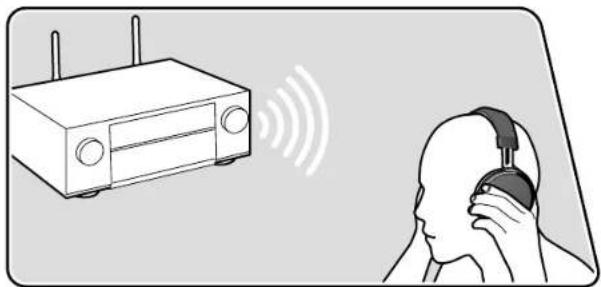
natural_image
Illustration of a router connected to a person's head with headphones, showing wireless signal waves (no text or symbols)The illustration shows an image.

Pairing
- Press the input selector you want to play.
- Select a source other than "BLUETOOTH". This function does not work if you select "BLUETOOTH".
- Press ☑ on the remote controller, and in the Home menu displayed, select "Network/Bluetooth" - "Bluetooth" - "Bluetooth Transmitter", and then press ENTER.
- Select either "On (Tx)" or "On (Main + Tx)" in "Bluetooth Transmitter". • If you select "On (Tx)", playback is from the BLUETOOTH wireless technology enabled device only, and if you select "On (Main + Tx)", playback is from both the BLUETOOTH wireless technology enabled device and the main unit.

- In "Search Devices", press ENTER.
- The search starts for BLUETOOTH wireless technology enabled devices that are able to receive, then a list of relevant devices is displayed.
- Select the device you want to output the audio from, and when you press ENTER the message "Now Pairing..." is displayed and the two are paired.
- Depending on the BLUETOOTH wireless technology enabled device, you may need to pair manually. If the device name does not appear in the list, check the settings of the BLUETOOTH wireless technology enabled device.





Playing Back
- Do the play operations on the AV component connected to this unit. Do the play operations on this unit when the input is TUNER or NET.
- If "Variable" has been selected for the "Output Level", the volume can be adjusted on this unit. Adjust to a suitable volume on the connected BLUETOOTH wireless technology enabled device beforehand. If "Fixed" is selected, adjust the volume on the BLUETOOTH wireless technology enabled device.
- You cannot transmit audio to multiple BLUETOOTH wireless technology enabled devices from this unit.
- The coverage area is approx. 48'/15 m. Note that connection is not always guaranteed with all BLUETOOTH enabled devices.
-
When "Bluetooth Transmitter" is "On (Tx)" or "On (Main + Tx)" and in the following cases, when this unit detects a paired BLUETOOTH wireless technology enabled device, it will automatically reconnect with that device.
-
When the power is turned on again after the unit is switched to standby
- While other than "BLUETOOTH" is selected
- When the "NET" input is selected and there is audio output from a network service/content (some services excluded)
When not using this function, select "Off" in "Bluetooth Transmitter" to cancel the connection. Also disconnect on the receiving device (if disconnection is possible on the receiving device).
- Audio cannot be output from a BLUETOOTH wireless technology enabled device in the following cases:
- When the audio file is DSD format
-
When playing audio from one of the following network services:
Chromecast built-in, Amazon Alexa, AirPlay, DTS Play-Fi -
Sound quality adjustments and listening modes of this unit cannot be applied to the output audio.
- This function can be used in the main room (where this unit is located). This function turns off if you turn on the Multi-zone function which outputs audio from a separate room (ZONE 2/ZONE 3).






Listening To the Radio (North American and Taiwanese models)
You can receive AM/FM radio stations on this unit with the built-in tuner.
Listening To the AM/FM Radio

Tuning into a Radio Station
Perform the following procedure when this unit is on.
■ Tuning Automatically
- Press TUNER repeatedly to select either "AM" or "FM".
- Press MODE repeatedly to display "TunMode: Auto" on the display.
TunMode: Auto
- When you press the cursors ▲, automatic tuning starts, and searching stops when a station is found. When tuned in to a radio station, the "TUNED" indicator on the display lights up. When tuned in to an FM radio station, the "STEREO" indicator lights up.
When FM broadcasts reception is poor: Perform the procedure for "Tuning Manually" (→p89). Note that if you tune manually, the reception for FM broadcasts will be monaural rather than stereo, irrespective of the sensitivity of the reception.






■ Tuning Manually
Note that if you tune manually, the reception for FM broadcasts will be monaural rather than stereo, irrespective of the sensitivity of the reception.
-
Press TUNER repeatedly to select either "AM" or "FM".
-
Press MODE repeatedly to display "TunMode: Manual" on the display.
TunMode:Manual
- While pressing the cursors ▲ . Select the desired radio station.
- Each time you press the cursors ▲, the frequency changes by 1 step. If the button is held down, the frequency changes continuously, and if the button is released, the frequency stops changing.

■ Frequency step setting
Press ☑ on the remote controller, and from Home displayed select "System Setup" - "Miscellaneous" - "Tuner" - "AM/FM Frequency Step", and then select the frequency step for your area. Note that when this setting is changed, all radio presets are deleted.




☐ Presetting a Radio Station ( p90)


Presetting a Radio Station
Playback
■ Registration Procedure
You can preset up to 40 of your favorite radio stations.
After tuning in to the radio station you want to register, perform the following procedure.
- Press + Fav so that the preset number on the display blinks.
FM 87.5 MHz
- While the preset number is blinking (approx. 8 seconds), repeatedly press the cursors ◀ to select a number between 1 and 40.
- Press + Fav again to register the station. When the station is registered, the preset number stops blinking. Repeat this steps to register your favorite radio stations.

■ Selecting a Preset Radio Station
- Press TUNER.
- Press the cursors ◀ to select a preset number.
■ Deleting a Preset Radio Station
- Press TUNER.
- Press the cursors ◀ to select the preset number to delete.
- After pressing +Fav, press CLEAR while the preset number is blinking, and delete the preset number. When deleted, the number on the display disappears.






AV Adjust
You can quickly set convenient features such as adjusting sound quality.
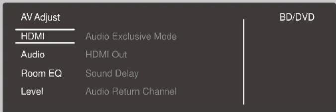
You can make the settings on the TV screen while playing something. Press ✿ on the remote controller to display the "AV Adjust" menu.
Select the item with the cursor ▲ buttons of the remote controller and press ENTER to confirm your selection.
Use the cursors to change the settings.
• To return to the previous screen, press ↩
• To exit the settings, press
Note
- When the input signals are ones that need a high bandwidth, such as 8K signals, the "AV Adjust" may not be displayed.
HDMI
Audio Exclusive Mode: You can make the HDMI IN 1 jack exclusively for audio to improve sound quality. Not that when this is set to on, the output of video signals will stop and there will be no display on the TV screen.
- The display will appear on the TV screen when you press, out the video signal out is stopped again when you press again.
HDMI Out: Select the HDMI OUT jack to output video signals from "MAIN", "SUB", and "MAIN+SUB".
Sound Delay: If the video is behind the audio, you can delay the audio to offset the gap. Different settings can be set for each input selector.
- It cannot be set if the listening mode is Pure Direct and the input signal is either analog or DSD.
Audio Return Channel: You can enjoy the sound of the HDMI-connected ARC-compatible TV through the speakers connected to the unit. Select "On" when listening to the audio of TV using the speakers of this unit. Select "Off" when the ARC function is not used.




Playback

Audio
Sound Retriever: Improve the quality of the compressed audio. Playback sound of lossy compressed files such as MP3 will be improved. The setting can be separately set to each input selector. The setting is effective in the signals of 48 kHz or less. The setting is not effective in the bitstream signals.
- It cannot be set if the listening mode is Direct or Pure Direct.
- This cannot be selected when either of the slots is selected with "Dirac Live" (→p93).
Midnight: Make small sounds easily heard. It is useful when you need to reduce the volume while watching a movie late night.
- It cannot be set if the listening mode is Direct or Pure Direct.
- The setting cannot be used in the following cases.
- If "Loudness Management" is set to "Off" when playing Dolby Digital Plus or Dolby TrueHD
- When the input signal is DTS:X and "Dialog Control" is other than 0 dB
Stereo Assign: This function enables you to select a pair of speakers to output stereo sound. Apart from the front speakers (Front), you can select the Surround speakers (Surround), Surround Back speakers (Surround Back), Height 1 speakers (Height 1), and Height 2 speakers (Height 2).
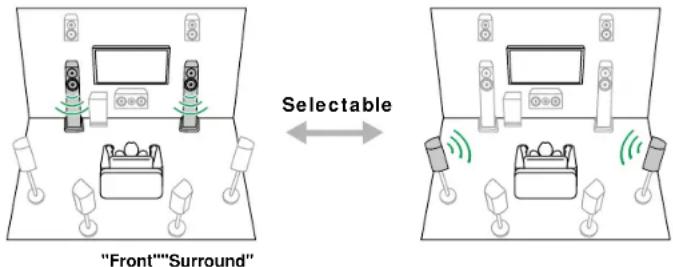
- The listening mode switches to "Stereo" if the audio output destination is changed.
Zone B: Select a method of outputting audio to ZONE B from among "Off", "On (A+B)" and "On (B)".
- In the following cases, "Zone B" cannot be selected. - When ZONE 2 is On
- When "System Setup" - "Speaker" - "Configuration" - "Zone 2 Preout" (→p136) on the Home screen is set to "Zone 2"
Auto Phase Control+: The low frequencies are recorded with a delay for some discs not made according to phase control standards. This function corrects the phase shift when playing such discs. When "Auto" is selected, in addition to the low frequency delay, the polarity and correlation are also detected and corrected.
- It cannot be set if the listening mode is Pure Direct.
- This cannot be selected when either of the slots is selected with "Dirac Live" (→p93).
AV Direct Mode: Sound quality can be improved by limiting the activity of digital circuits and thereby suppressing the noise that is generated by them. (→p115)
Dialog Lifted Up: By adjusting the localization of the center elements, you can make it easier to hear dialog in movies or give more prominence to the vocals in music. If you are using front high speakers, you can select from "1" (low) to "4" (high).
- The function cannot be set in the following cases.
– When the Front High speakers are not enabled
- When the DIALOG button (→p19) function is being used
- When "Dialog Control" (→p142) has been set
- When the listening mode is Direct or Pure Direct




Audio Scaler: By selecting "Auto", "Hi-bit 32", "Upsampling", and "Digital Filter" are each automatically set to the optimum values so that you get the high-quality playback of music files and CDs. The setting can be separately set to each input selector.
Select "Manual" if you want to manually adjust "Hi-bit 32", "Upsampling", and "Digital Filter".
Hi-bit 32: By expanding the dynamic range of digital audio signal sources such as CDs, DVDs, and BDs, it is possible to achieve a smoother and more refined sound. The setting can be separately set to each input selector. This can be set when the sampling frequency is 44.1 kHz or more.
- This cannot be set if "Auto" is selected for "Audio Scalar".
Upsampling: By increasing the sampling frequency of PCM 2 channel audio by a factor of 2 or 4, you can achieve high-quality sound reproduction. The setting can be separately set to each input selector. This can be set when the sampling frequency is between 44.1 kHz and 96 kHz. This function works in the Direct, Pure Direct, and Stereo listening modes.
- This cannot be set if "Auto" is selected for "Audio Scalar".
Digital Filter: You can switch the type of digital filter in the AUDIO DAC (digital analog converter). You can choose "Slow" (gives the sound a soft and fluid feel), "Sharp" (gives the sound more structure and firmer feel), or "Short" (gives the sound a feeling of a quick start and moving forward). The setting can be separately set to each input selector. This can be set when the sampling frequency is 44.1 kHz or more.
- This cannot be set if "Auto" is selected for "Audio Scalar".
Reflex Optimizer: Enhance the reflection effect of Dolby enabled speakers from the ceiling. This setting can be selected when "System Setup" - "Speaker" - "Configuration" - "Height 1 Speaker"/"Height 2 Speaker" is set to "Dolby Speaker".
- It cannot be set if the listening mode is Pure Direct.
Room EQ
Dirac Live (*1): You can select the slots with registered filters measured with Dirac Live (→p178, p182) from "Slot1" to "Slot3".
- The Dirac Live measurement results are saved in "Slot1" to "Slot3", but you are able to register your own original filter with "Manual Adjust" (→p184).
- This cannot be selected when measurements are made using "Full Auto MCACC".
MCACC EQ (*1)(*3): Enable or disable the equalizer function that corrects for distortion caused by the acoustic environment of the room.
Phase Control (*1): Correct phase disturbance in the low range to enhance the bass. This enables you to achieve powerful bass reproduction that is faithful to the original sound.
MCACC Memory: From MCACC Memory 1 to 3 where speaker settings calibrated with "Full Auto MCACC" or "Manual MCACC" are saved, select which Memory to use.
Theater Filter (*2)(*3): Adjust the soundtrack that was processed to enhance its high pitch range, in order to make it suitable for home theater.
Standing Wave (*1)(*3): Setting this "On" will control the effect of the standing wave generated by the sound wave reflected by wall or similar interfering with the original sound wave.
(*1) It cannot be set if the listening mode is Pure Direct.
(*2) It cannot be set if the listening mode is Direct or Pure Direct.
(*3) This function cannot be used if Dirac Live (→p178, p182) is being used. Furthermore, there is no effect even if it can be selected.


Playback

Level
Front: Adjust the speaker level of the front speakers while listening to the sound.
Center: Adjust the speaker level of the center speaker while listening to the sound.
Subwoofer 1 / Subwoofer 2: Adjust the speaker level of the subwoofer while listening to the sound.
- If you set the unit to the standby mode, the adjustments you made will be restored to the previous statuses.


Spotify

Spotify®
Use your phone, tablet or computer as a remote control for Spotify. Go to spotify.com/connect to learn how.






AirPlay®
By connecting this unit to the same network as iOS devices, such as that of iPhone ^ , iPod touch ^ and iPad ^ , you can enjoy music files on iOS devices wirelessly.
- Update the OS version on your iOS device to the latest version.
- Depending on the iOS version, operation screens or operation procedures on the iOS device may be different. For details, refer to the operating instructions for the iOS device.
Basic Operations

e.g., iOS 10
- Connect the iOS device to the access point where this unit is connected via network.
- Tap the AirPlay icon 📊 the play screen of the music app on an iOS device that supports AirPlay and select this unit from the list of devices displayed.
- Play the music file on the iOS device.
- If "System Setup" - "Hardware" - "Power Management" - "Network Standby" is set to "Off" in the Home, manually turn the unit on and then press NET on the remote controller. In the factory default setting, the Network Standby function (→p149) is set to On.
- Due to the characteristics of AirPlay wireless technology, the sound produced on this unit may slightly be behind the sound played on the AirPlay-enabled device.
You can also play the music files on a PC with iTunes (Ver. 10.2 or later) equipped. Confirm that this unit and the PC are connected to the same network beforehand. Then, press NET on the remote controller. Next, click the AirPlay icon 🔒 in iTunes, select this unit from the displayed devices, and start play of a music file.





Playing Back on multiple devices (AirPlay2)

e.g., iOS 11.4
This unit supports AirPlay2. If the version of the iOS device is iOS11.4 or later, you can play the music file on the iOS device simultaneously on this device and on another device that supports AirPlay2.
- Connect the iOS device to the access point where this unit is connected via network.
-
Tap the AirPlay icon on the play screen of the music play application on the iOS device, and select this unit and AirPlay2-supported devices to play from the displayed devices.
-
AirPlay2-supported devices are displayed with white circle on the right side.
-
Multiple AirPlay2-supported devices can be selected.
• The volume can be adjusted on individual devices. -
Play the music file on the iOS device.
-
If "System Setup" - "Hardware" - "Power Management" - "Network Standby" is set to "Off" in the Home, manually turn the unit on and then press NET on the remote controller. In the factory default setting, the Network Standby function (→p149) is set to On.
- Due to the characteristics of AirPlay wireless technology, the sound produced on this unit may slightly be behind the sound played on the AirPlay-enabled device.
You can also play the music files on a PC with iTunes (Ver. 12.8 or later) equipped. Confirm that this unit and the PC are connected to the same network beforehand. Then, press NET on the remote controller. Next, click the AirPlay icon 🔒 in iTunes, select this unit and AirPlay2-supported devices to play from the displayed devices, and start play of a music file.





DTS Play-Fi®
dts play-fi
https://play-fi.com/
When connecting this unit to the same network as mobile devices, such as a smartphone and tablet, you can enjoy music played on the mobile device wirelessly. Music from a streaming distribution service or music in the music library on a mobile device can be played. This function also supports a playlist on iTunes. Also, connecting multiple speakers supporting DTS Play-Fi on the same network will enable "Group playback" that plays the same music in separate rooms at home. To enjoy this function, download Pioneer Music Control App (available on iOS or Android™).

Playing Back
- Download Pioneer Music Control App using your mobile device. https://intl.pioneer-audiovisual.com/playfi/app_p.html





- Connect the mobile device to the network where this unit is connected.
- Starting up Pioneer Music Control App will automatically display compatible devices.
-
Select this device from the compatible devices. Then, a list of applications such as a music streaming distribution service is displayed. Select the content to play, and perform operation according to the on-screen instructions.
-
If "System Setup" - "Hardware" - "Power Management" - "Network Standby" is set to "Off" in the Home, manually turn the unit on and then press NET on the remote controller. In the factory default setting, the Network Standby function (→p149) is set to On.
- For detailed operation and FAQ, visit the following URL. https://intl.pioneer-audiovisual.com/playfi/info_p.html
- To use a music streaming distribution service, user registration may be required.
-
This unit does not support the following DTS Play-Fi functions.
-
Spotify
– Wireless Surround Sound
– Line In Rebroadcast - Internet Radio
- Some of the settings in the "Setup menu" cannot be changed on this unit. To change those settings, cancel the connection of this unit from the application.


Amazon Alexa
Alexa is a cloud-based voice service developed by Amazon. When this unit is registered with an Amazon account, you can use a terminal with Amazon Alexa (an Amazon Echo, etc.) or Amazon Alexa App (available on iOS and Android™) to perform operations such as adjusting the volume of this unit or playing music using voice commands.
- You need an Amazon account to use Amazon Alexa. For more information, see the Amazon website.

natural_image
Line drawing of a person emitting sound waves from a cylindrical device (no text or symbols)



Registering this unit with an Amazon account
- Register with the Amazon account on Pioneer Remote App. This cannot be set with operations on this unit.
Refer to "Pioneer Remote App" (→p181) for information about the app. - Start Pioneer Remote App and tap the unit when displayed.
- Tap "NET" or "NETWORK" at the top of the Pioneer Remote App screen, and after switching to the network menu, tap the "amazon alexa" icon.
- If the login screen is not displayed, but rather a screen prompting installation of Service Unlocker, then install that first.

Available services may differ depending on your area.
-
Tap "Start Setup", and in the Setup screen, select the language and register the device name. Select the same language as the one you have selected for your other terminals with Amazon Alexa (an Amazon Echo, etc.). For the device name, use one that can easily be called up vocally.
For example: Speaker -
Tap "Next" to display the Amazon Alexa screen.
-
Follow the on screen instructions to enter the Amazon account information, such as your email address and password, to log into Amazon (*1). After logging in, tap "Allow" and register this unit with an Amazon account.
(*1) Log in using the same account as other terminals with Amazon Alexa.


- When registration is finished, the screen returns to the one for Pioneer Remote App. Follow the on screen instructions and talk to the terminal with Amazon Alexa (an Amazon Echo, etc.), and confirm that you can use voice commands.
For example: "Alexa, raise the volume of the speaker (*2)"
"Alexa, play music from the speaker (*2)"
(*2) Use the device name you registered in Step 4 when talking.

flowchart
graph LR
    A["Does it work?"] --> B["Does it work?"]
    B --> C["Next"]
    C --> D["Complete"]
Operating this unit
You can use voice commands to adjust the volume on this unit, start and stop music, and skip music up or down.
- With the unit on, speak at the terminal with Amazon Alexa (an Amazon Echo, etc.). When using the Amazon Alexa app, after starting the app, tap the Alexa logo and speak at the mobile device.
For example: "Alexa, raise the volume of the speaker (*3)"
"Alexa, play music from the speaker (*3)"
(*3) Use the device name you registered in Step 4 of "Registering this unit with an Amazon account" when talking.
- Refer to the website for details about voice commands. (Click here □)
- Refer to the Amazon websites for information about operation of the Amazon Alexa app.






Amazon Music
amazon music
You can use the music distribution service provided by Amazon by registering with Amazon Music.
- To play Amazon Music you need to have an Amazon account and to be a member of Amazon Prime and Amazon Music Unlimited. For more information, see the Amazon website.
Amazon Music is now available in several countries. If Amazon Music is not available in your country, please visit https://music.amazon.com/ for more info.
Registering This Unit with Amazon Music
-
Register with the Amazon account on Pioneer Remote App. This cannot be set with operations on this unit. Refer to "Pioneer Remote App" (→p181) for information about the app.
-
Start Pioneer Remote App and tap the unit when displayed.
-
Tap "NET" or "NETWORK" at the top of the Pioneer Remote App screen, and after switching to the network screen, tap the "Amazon Music" icon to display the Amazon Music login screen. (Depending on the model, the icon names may be different.)
- If the login screen is not displayed, but rather a screen prompting installation of Service Unlocker, then install that first.

Available services may differ depending on your area.
- Enter the information required for the Amazon account, such as your email address and password, to log into Amazon. The Amazon Music menu is displayed when login is successful and this unit is registered. To continue to start play, proceed to step 3 in the next section.





Playing Amazon Music using the Pioneer Remote App
- Start the Pioneer Remote App. This unit is displayed automatically when the app is started, so tap the unit when displayed to select it.
- Tap "NET" or "NETWORK" at the top of the screen, and after switching to the network screen, tap the "Amazon Music" icon.
- Select the content that you want to play in the menu screen for Amazon Music and start play.
Playing Amazon Music using the remote controller
- Switch the input on the TV to the input connected to the unit.
- Pressing NET will display the Network Functions list screen on the TV.
- Select "Amazon Music" with the cursors and press ENTER to confirm.
- Select the content that you want to play in the menu screen for Amazon Music and start play.



TIDAL
TIDAL
Registering this unit with TIDAL allows you to enjoy the music distribution service provided by TIDAL. You can register this unit on the screen of Pioneer Remote App by downloading Pioneer Remote App (available on iOS or Android™) to mobile devices such as a smartphone and tablet.
You need a TIDAL account to play back TIDAL. For more information, see the TIDAL website.

Registering this unit with TIDAL
- You can register this unit with TIDAL using Pioneer Remote App. The registration cannot be performed by operation of this unit.
- Connect this unit to your home network by the network settings on this unit.
- Download Pioneer Remote App using your mobile device.
- Connect the mobile device to the network where this unit is connected.
- Start up Pioneer Remote App to automatically display this unit. Tap and select this unit displayed.
- Tap "NET" or "NETWORK" on the upper part of the Pioneer Remote App's screen to switch to the network menu. Then tap the "TIDAL" icon to display the login screen of TIDAL. (Depending on the model, the icon names may be different.)
- If the login screen is not displayed but an update or installation screen is displayed instead, perform the update or installation according to the
onscreen instructions.

Available services may differ depending on your area.
- Enter the TIDAL account information such as login ID and password to log in to TIDAL. When the login is successful and this unit is registered, the TIDAL menu is displayed. For playback, proceed to step 3 in the next section.
Playing TIDAL
- Start up Pioneer Remote App. This unit is automatically displayed after startup. Then, tap and select this unit displayed.
- Tap "NET" or "NETWORK" on the upper part of the screen to switch to the network screen. Then tap the "TIDAL" icon.
- Select the content to play from the menu screen of TIDAL to start playback.
- To play TIDAL using the remote controller, operate the input selector on the remote controller to display the network menu, and select "TIDAL" from the menu.





Connecting the Sonos System for Playback
Works with
SONOS
Once your unit is connected to the Sonos Connect you will be able to send any music or source on your Sonos App to the unit. By going through the Sonos Connect, you can play your unit through other Sonos devices in the network in the same group, or you can just play on your unit. Further, the power of your unit turns on automatically when music starts playing on the Sonos App, and the linked function to switch input works.
- If "System Setup" - "Hardware" - "Power Management" - "Network Standby" is set to "Off" in the Home, manually turn the unit on and then press NET on the remote controller. In the factory default setting, the Network Standby function (→p149) is set to On.
- You can register a maximum of 3 Sonos Connect.
Necessary Equipment
- Sonos Connect
- RCA audio cable (supplied with Sonos Connect)




How to Connect This Unit and Sonos Connect
-
Connect the Sonos Connect to the AUDIO IN jack of this unit with the RCA audio cable supplied with the Sonos Connect. Any input can be used other than the PHONO jack.
-
You can also connect with a digital cable. For details, refer to the instruction manual of the Sonos.
- You can rename the input that is displayed on the unit to a more logical name. For example, you can change the name of input that the Sonos Connect is plugged into from "CD" (or another input selector name) to "SONOS". Press the ⏻ button on the remote controller to display the Home screen, and select "System Setup" - "Source" - "Name Edit" to change the name.
Setting Up
A setup is required to play Sonos on this unit. Make the setting according to the following procedure.
- Press the button on the remote controller to display the Home screen, select "System Setup" - "Hardware" - "Works with SONOS", and press the ENTER button.
- Select the following items with the cursors ▲ and set each item. Input Selector: Enable the interlocking function with the Sonos Connect. With the cursors ◀, ▶ select the input selector to which the Sonos Connect is connected.
Connected Device:
Press the ENTER button to display Sonos devices connected to the same network as the network of this unit. Select the Sonos Connect connected to the unit and press the ENTER button.
- Products (e.g. Play:3 unequipped with an output terminal) other than the Sonos Connect are also displayed in the device list and selectable. In that case, when playback on the Sonos side starts, the input is switched, however, audio is not output. Select the room name of the connected


Sonos Connect.
- Up to 32 devices can be displayed on the Sonos product list screen. If you cannot find the Sonos Connect to be interlocked, return to the previous screen, turn off the product you do not want to interlock, and try again.
Output Zone:
With the cursors ◀, select the ZONE where you want to listen to the music.
"Main": Outputs audio only to the main room (where this unit is located).
"Zone 2": Outputs audio only to the separate room (ZONE 2).
"Main/Zone 2": Outputs audio to both the main room and separate room (ZONE 2).
"Zone 3": Outputs audio only to the separate room (ZONE 3).
"Main/Zone 3": Outputs audio to both the main room and separate room (ZONE 3).
"Zone 2/Zone 3": Outputs audio to both the separate rooms (ZONE 2 and ZONE 3).
"Main/Zone 2/Zone 3": Outputs audio to the main room and both separate rooms (ZONE 2 and ZONE 3).
Preset Volume:
You can set the volume that Sonos Connect will be played at beforehand. Select a value from "Last" (Volume level before entering standby mode),
"-∞ dB", and "-81.5 dB" to "+18.0 dB".
- When making the setting for the second and third unit, press the cursor ▼ several times to move to the next page, and change the menu from "SONOS-1" to "SONOS-2" or "SONOS-3".
Playing Sonos on This Unit
- Using your Sonos App select the music you want to listen to and send it to the room (or group) where your unit is located. We recommend naming your unit / Sonos Connect combination a friendly name like TV Room or Living Room where the equipment is located.
- If the input on your unit does not change automatically when play starts, try stopping play, then starting it again.
- When the "Volume Pass Through" mode has been selected with the Sonos App settings, you can use the Sonos App to control the volume of this unit. * You cannot use the "Preset Volume" function when the "Volume Pass Through" mode has been selected.






Internet Radio
By connecting this unit to an Internet-connected network, you can enjoy Internet radio services such as TuneIn Radio.
• To play Internet radio services, the network needs to be connected to the Internet.
- Depending on the Internet radio service, a user registration may be required on your PC beforehand. For details of each service, visit the website of each service.
Playing Back
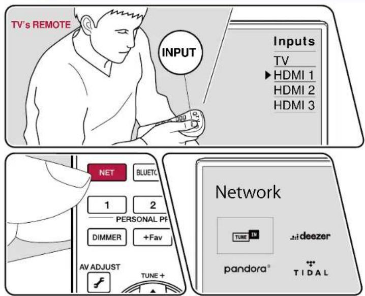
The illustration shows an image.
Perform the following procedure when this unit is on.
- Switch the input on the TV to the input connected to the unit.
- Pressing NET will display the Network Services list screen on the TV.
- Select your preferred Internet radio service using cursor, and press ENTER to confirm the selection.
- Following the on-screen instructions, select a radio station and program using cursor, and then press ENTER to play.
• To return to the previous screen, press ↩
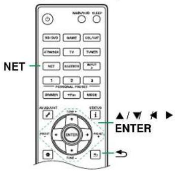



Internet Radio Service Menu
You can bookmark specific stations, or delete stations that have been bookmarked. The displayed menu varies according to the service being selected.
The menu icon 📁 is displayed while a station is being played. When only this icon is displayed, pressing ENTER will display the menu on the screen. When multiple icons are displayed, select the 📁 icon with the cursor, and press ENTER.
Regarding the Tuneln Radio Account
If you create an account on the Tuneln Radio website (tunein.com), and log in it from this unit, your favorite radio stations or programs you have followed on the website are automatically added to your "My Presets" on this unit. "My Presets" is displayed on the next level in the hierarchical structure of Tuneln Radio. To display a radio station added to "My Presets", you need log into Tuneln Radio from the unit. To log in, select "Login" - "I have a Tuneln account" in the "Tuneln Radio" top list on the unit, and then enter your user name and password.
- If you select "Login" on this unit, a registration code is displayed. By using this code, you can associate the device on the My Page section of the Tuneln Radio website so that you can log in from "Login" - "Login with a registration code" without entering the user name and password.





Multi-zone
You can enjoy 2 ch audio in the separate room (ZONE 2/ZONE 3) while performing playback in the main room (where this unit is located). The same source can be played back in the main room and ZONE 2/ZONE 3 simultaneously.

flowchart
graph TD
    A["Zone A (Main Room)"] --> B["Zone 2"]
    A --> C["Zone 3"]
    B --> D["Device 1"]
    B --> E["Device 2"]
    C --> F["Device 3"]
    style A fill:#f9f,stroke:#333
    style B fill:#ccf,stroke:#333
    style C fill:#ccf,stroke:#333
Using Pioneer Remote App (→p181) is convenient for operations of multi-zone playback. You can use it on mobile devices, such as a smartphone and tablet to which Pioneer Remote App (available on iOS or Android™) has been downloaded.

□ Playing Back (ZONE 2) (→p109)
□ Playing Back (ZONE 3) (→p111)




Playing Back (ZONE 2)
Playback
Note
- The audio from externally connected AV components can be output to ZONE 2 only when the audio is analog or 2 ch PCM signal. When the AV component is connected to this unit with an HDMI cable, digital coaxial cable or digital optical cable, change the audio output of the AV component to the PCM output.
- When outputting the video and audio input via HDMI to ZONE2, set "System Setup" - "Input/Output Assign" - "TV Out / OSD" - "Zone2 HDMI" (→p129) on the Home screen to "Use".
- You can only select the same source for the main room and separate room with the "NET" and "BLUETOOTH" input selectors. Furthermore, if you have "NET" selected in the main room and you then select "BLUETOOTH" in the separate room, the main room will also switch to "BLUETOOTH".
- It is not possible to select different stations in the main room and separate room with AM/FM broadcasts. (North American and Taiwanese models)
- DSD audio signals cannot be output to ZONE 2 with the "NET" input selector.
- If ZONE 2 is on, power consumption during standby will increase.
- This function turns off if you use "Transmitting audio from this unit to BLUETOOTH wireless technology enabled devices" (→p86).
Turning ZONE 2 On/Off
- Face the remote controller at the unit, and while pressing and holding the ZONE 2 HOLD button on the remote controller, press ON the main unit, press the ZONE 2 ON/OFF button.

"Z2" lights in the main unit display when ZONE 2 turns on. To turn ZONE 2 off, repeat the same procedure.

- When the power of this unit is switched to standby while using ZONE 2, the Z2 indicator lights dimly, and the mode switches to play only in the separate room. Furthermore, the mode switches to play only in the separate room when this unit is in standby mode and ZONE 2 is turned on.





Selecting a source to play in ZONE 2
- While pressing the ZONE 2 HOLD button on the remote controller, press the input selector of the input you want to play in the separate room. On the main unit, repeatedly press the ZONE CONTROL button to display "Z2" on the display, then within 8 seconds use the input selector dial to select the input you want to play in the separate room.

- Information of a connected device can be displayed on the TV screen in the separate room. While pressing and holding the ZONE 2 HOLD button on the remote controller, press the "1" button.
Adjusting the volume in ZONE 2
When ZONE 2 speakers are used
- While pressing the ZONE 2 HOLD button on the remote controller, adjust with the volume buttons. To control on the main unit, press the ZONE CONTROL button on the main unit and then within 8 seconds adjust with the MASTER VOLUME dial.

When using an Integrated amplifier in the separate room
- Use the volume dial on the integrated amplifier to adjust the volume.
- When connecting an integrated amplifier that does not have a volume control, in the System Setup menu, set "Multi Zone" - "Zone 2" - "Output Level" (→p152) to "Variable" (Default Value : Fixed). If you do not set this, the volume output will be very loud and there is a danger of damage to the integrated amplifier, speakers, etc. When connecting an integrated amplifier that has a volume control, leave this as "Fixed".




□ Playing Back (ZONE 3) (→p111)


Playing Back (ZONE 3)
Playback
Note
- Analog play of the audio from externally connected AV components is possible.
- To use Zone 3 speakers, in the Setup menu, set "Speaker" - "Configuration" - "Zone Speaker" (→p136) to "Zone 2/Zone 3".
- To use an integrated amplifier, in the System Setup menu, set "Speaker" - "Configuration" (→p134) to one of the following:
- Set "Speaker Channels" to "2.1 ch", "3.1 ch", "4.1 ch", or "5.1 ch"
- Set "Speaker Channels" to "2.1.2 ch", "3.1.2 ch", "4.1.2 ch", or "5.1.2 ch", and set "Bi-Amp" and "Zone Speaker" to "No"
- You can only select the same source for the main room and separate room with the "NET" and "BLUETOOTH" input selectors. Furthermore, if you have "NET" selected in the main room and you then select "BLUETOOTH" in the separate room, the main room will also switch to "BLUETOOTH".
- It is not possible to select different stations in the main room and separate room with AM/FM broadcasts. (North American and Taiwanese models)
- DSD audio signals cannot be output to ZONE 3 with the "NET" input selector.
- If ZONE 3 is on, power consumption during standby will increase.
- This function turns off if you use "Transmitting audio from this unit to BLUETOOTH wireless technology enabled devices" (→p86).
Turning ZONE 3 On/Off
- Face the remote controller at the unit, and while pressing and holding the ZONE 3 HOLD button on the remote controller, press ON the main unit, press the ZONE 3 ON/OFF button.
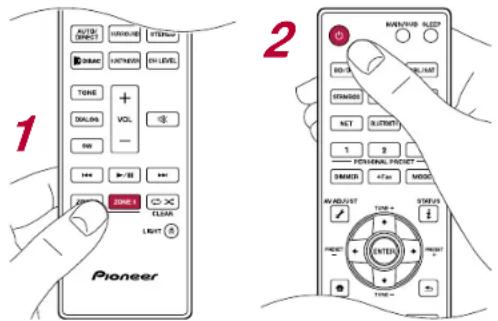
"Z3" lights in the main unit display when ZONE 3 turns on. To turn ZONE 3 off, repeat the same procedure.
Z3
- When the power of this unit is switched to standby while using ZONE 3, the Z3 indicator lights dimly, and the mode switches to play only in the separate room. Furthermore, the mode switches to play only in the separate room when this unit is in standby mode and ZONE 3 is turned on.






Selecting a source to play in ZONE 3
- While pressing the ZONE 3 HOLD button on the remote controller, press the input selector of the input you want to play in the separate room. On the main unit, repeatedly press the ZONE CONTROL button to display "Z3" on the display, then within 8 seconds use the input selector dial to select the input you want to play in the separate room.

Adjusting the volume in ZONE 3
When ZONE 3 speakers are used
- While pressing the ZONE 3 HOLD button on the remote controller, adjust with the volume buttons. To control on the main unit, press the ZONE CONTROL button on the main unit and then within 8 seconds adjust with the MASTER VOLUME dial.

When using an Integrated amplifier in the separate room
- Use the volume dial on the integrated amplifier to adjust the volume. When using an integrated amplifier that does not have a volume control, adjust using the same procedure described in "When ZONE 3 speakers are used". When connecting an integrated amplifier that does not have a volume control, in the System Setup menu, set "Multi Zone" - "Zone 3" - "Output Level" (→p153) to "Variable". If you do not set this, the volume output will be very loud and there is a danger of damage to the integrated amplifier, speakers, etc.






Using PERSONAL PRESET
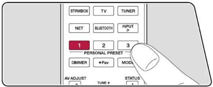
Registration
You can register settings (→p114) such as the current input selector and listening mode with the three PERSONAL PRESET buttons, and call a registered setting in a single operation.
e.g.) Pressing the PERSONAL PRESET button will automatically switch the input selector to "TUNER" to receive the registered station. Also, the listening mode and volume level are switched as registered.
Perform the following steps in the state of the setting to register.
- Press and hold any of the 1 to 3 buttons of PERSONAL PRESET.
- "Preset Written" appears on the display, and the setting is registered. If registration has already been made, the registered setting is overwritten.



Settings that can be registered
The following settings can be registered with PERSONAL PRESET.
- Input selector (Network service or AM/FM radio stations(*) can also be registered.)
* NorthAmerican and Taiwanese models
- Output destination (HDMI)
- Listening mode
- Volume level (Upper limit "0.0 dB")
(When ZONE 2/ZONE 3 is on, the volume level of ZONE 2/ZONE 3 is also
registered.)
- Output destination (Multi Zone)
- MCACC Memory
- MCACC EQ
- Standing Wave
- Phase Control
– Auto Phase Control Plus
- Sound Delay
– Sound Retriever function's "On" and "Off"
- TREBLE/BASS/DIALOG, etc.
* When AM/FM radio stations are registered, TUNER's preset numbers "38", "39" and "40" (→p90) are overwritten.
Using the registered settings
- Press any of the 1 to 3 buttons of PERSONAL PRESET with which settings have been registered.
Checking the registered settings
-
Press 🔗 to display the Home screen, select "System Setup" - "Input/Output Assign" - "PERSONAL PRESET Information" (→p132), and press ENTER.
-
The registered settings are displayed in the list.
- Some of the items such as the Sound Retriever function are not displayed in the list.



AV Direct Mode
AV Direct Mode can improve sound quality by limiting the activity of digital circuits and thereby suppressing the noise that is generated by them. You can choose from "AV Direct" which temporarily stops communications such as via the network, BLUETOOTH, and USB, and "AV Direct Net Off" which turns off the power for some digital circuits. Either one can be used to play the audio from external devices connected to the input terminals on this unit.
This function is not available with a source to which a Sonos Connect ( p104 ) is connected.
Using "AV Direct"
You can make the settings on the TV screen while playing something.
-
Press on the remote controller to display the "AV Adjust".
-
In the "AV Adjust" select "Audio" - "AV Direct Mode" to switch On/Off.
- "AV Direct" automatically switches off when you perform any of the following operations:
- Set this unit to standby.
- Switch input source to "NET" or "BLUETOOTH".
- Select the source to which the Sonos Connect (→p104) is connected.
– Display the Home screen.
- Switch On Multi-zone function.
- Depending on the functions used, the track name may be displayed on the display and "Off" for "AV Direct" may not be displayed.
Using "AV Direct Net Off"
- While pressing and holding the ZONE CONTROL button on the main unit, press the STATUS button so that "AV Direct.Net Off" appears on the display of the main unit. The power of some of the digital circuits are turned "Off".
- "AV DIRECT Net Off" automatically switches off when you perform any of the following operations:
- Set this unit to standby.
- Switch input source to "NET" or "BLUETOOTH".
- Select the source to which the Sonos Connect ( p104) is connected.
- Display the Setup menu.
- Switch On Multi-zone function.






Playing music files saved on a USB storage device
You can play music files stored on a USB storage device.
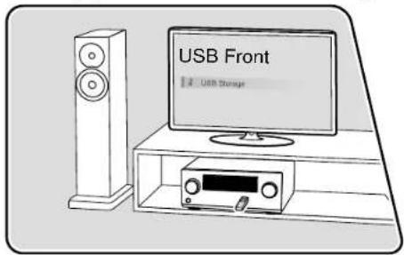
Perform the following procedure when this unit is on.
- Switch the input on the TV to the input connected to the unit.
- Plug your USB storage device with the music files into the USB port either on the front panel or rear panel of this unit.
-
Press INPUT > and select "USB Front" or "USB Rear".
-
If the "USB" indicator blinks on the display, check whether the USB storage device is plugged in properly.
-
Do not unplug the USB storage device while "Connecting..." is being displayed on the display. This may cause data corruption or malfunction.
-
Press ENTER in the next screen. The list of folders and music files on the USB storage device is displayed. Select the folder with the cursors, and press ENTER to confirm your selection.
-
Select the music file with the cursors, and then press ENTER to start playback.

• To return to the previous screen, press ↗
- Characters that cannot be displayed on this unit appear with "*".
- The USB port of this unit complies with the USB 2.0 standard. The transfer speed may be insufficient for some content you play, and sound interruptions,






etc. may occur.
- When playing files recorded with VBR (Variable bit-rate), the playback time may not be displayed correctly.
- This unit supports the gapless playback of the USB storage device in the following conditions.
When continuously playing WAV, FLAC and Apple Lossless files with the same format, sampling frequency, the number of channels and quantization bit rate.
- To display an album title, artist name and album art of a file in WAV format, make the folder structure and file names as shown below when saving music files. The album art can be displayed by saving a .jpg file to display on the screen in the folder of bottom level. Note that a large volume of .jpg file may take time to be displayed, or may not be displayed.
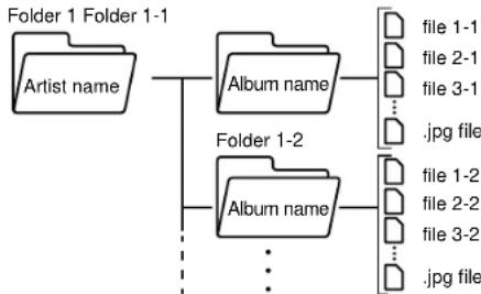
flowchart
graph TD
    A["Folder 1 Folder 1-1\nArtist name"] --> B["Folder 1-2\nAlbum name"]
    B --> C["..."]
    B --> D["..."]
    B --> E["..."]
    B --> F["..."]
    B --> G["..."]
    B --> H["..."]
    B --> I["..."]
    B --> J["..."]
    B --> K["..."]
    B --> L["..."]
    B --> M["..."]
    B --> N["..."]
    B --> O["..."]
    B --> P["..."]
    B --> Q["..."]
    B --> R["..."]
    B --> S["..."]
    B --> T["..."]
    B --> U["..."]
    B --> V["..."]
    B --> W["..."]
    B --> X["..."]
    B --> Y["..."]
    B --> Z["..."]
    B --> AA["..."]
    B --> AB["..."]
    B --> AC["..."]
    B --> AD["..."]
    B --> AE["..."]
    B --> AF["..."]
    B --> AG["..."]
    B --> AH["..."]
    B --> AI["..."]
    B --> AJ["..."]
    B --> AK["..."]
    B --> AL["..."]
    B --> AM["..."]
    B --> AN["..."]
    B --> AO["..."]
    B --> AP["..."]
    B --> AQ["..."]
    B --> AR["..."]
    B --> AS["..."]
    B --> AT["..."]
    B --> AU["..."]
    B --> AV["..."]
    B --> AW["..."]
    B --> AX["..."]
    B --> AY["..."]
    B --> AZ["..."]
    B --> BA["..."]
    B --> BB["..."]
    B --> BC["..."]
    B --> BD["..."]
    B --> BE["..."]
    B --> BF["..."]
    B --> BG["..."]
    B --> BH["..."]
    B --> BI["..."]
    B --> BJ["..."]
    B --> BK["..."]
    B --> BL["..."]
    B --> BM["..."]
    B --> BN["..."]
    B --> BO["..."]
    B --> BP["..."]
    B --> BQ["..."]
    B --> BR["..."]
    B --> BS["..."]
    B --> BT["..."]
    B --> BU["..."]
    B --> BV["..."]
    B --> BW["..."]
    B --> BX["..."]
    B --> BY["..."]
    B --> BZ["..."]
    B --> CA["..."]
    B --> CB["..."]
    B --> CC["..."]
    B --> CD["..."]
    B --> CE["..."]
    B --> CF["..."]
    B --> CG["..."]
    B --> CH["..."]
    B --> CI["..."]
    B --> CJ["..."]
    B --> CK["..."]
USB Storage Device Requirements
- This unit can use USB storage devices that comply with the USB mass storage class standard. Also the format of USB storage devices supports FAT16 or FAT32 file system format.
- If the USB storage device has been partitioned, each section will be treated as an independent device.
- Up to 20,000 tracks per folder are supported, and folders can be nested up to 16 levels deep.
- USB hubs and USB storage devices with hub functions are not supported. Do not connect these devices to the unit.
- If an AC adapter is supplied with the USB storage device, connect the AC adapter, and use it with a household outlet.
- USB storage devices with security functions are not supported on this unit.
- Media inserted to the USB card reader may not be available in this function. Furthermore, depending on the USB storage device, proper reading of the contents may not be possible.
- In use of a USB storage device, our company accepts no responsibility whatsoever for the loss or modification of data stored on a USB storage device, or malfunction of the USB storage device. We recommend that you back up the data stored on a USB storage device before using it with this unit.
- Note that operation is not always guaranteed for all USB storage devices.





Music Server

Music Server
Streaming play of music files stored on PCs or NAS devices connected to the same network as this unit is supported.
Music Server notes
- The network servers this unit is compatible with are those PCs with players installed that have the server functionality of Windows Media ^ Player 12, or NAS that are compatible with home network functionality. When using Windows Media ^ Player 12, you need to make the settings beforehand. Note that with PCs, only music files registered in the library of Windows Media ^ Player can be played.
- When playing files recorded with VBR (Variable bit-rate), the playback time may not be displayed correctly.
- For music files on a server, up to 20,000 tracks per folder are supported, and folders can be nested up to 16 levels deep.
- Depending on the type of media server, the unit may not recognize it, or may not be able to play its music files.
Windows Media® Player 12 settings
- Turn on your PC, and start Windows Media ^® Player 12.
- In the "Stream" menu, select "Turn on media streaming" to display a dialog box.
- If the media streaming is already turned on, select "More streaming options..." in the "Stream" menu to display the list of playback devices in the network, and then go to step 4.
- Click "Turn on media streaming" to display the list of playback devices in the network.
- Select this unit in "Media streaming options" and check that it is set to "Allow".
- Click "OK" to close the dialog.
- Open the "Stream" menu and confirm that "Allow remote control of my Player..." is checked.
- Depending on the version of Windows Media ^ Player, the names of items to select may differ from the above description.



□ Playing Back ( →p119)


Playing Back
Playback
Perform the following procedure when this unit is on.
- Switch the input on the TV to the input connected to the unit.
- Start the server (Windows Media ^® Player 12 or NAS device) containing the music files to play.
- Make sure that the PC or NAS is properly connected to the same network as this unit.
- Press NET to display the network service list screen. • If the "NET" indicator on the display blinks, the unit is not properly connected to the network. Check the connection.

- With the cursors, select "Music Server", and then press ENTER.
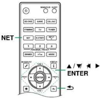




- Select the target server with the cursors, and press ENTER to display the items list screen.
- This unit cannot access pictures and videos stored on servers. - Depending on the server sharing settings, contents stored on the server may not be displayed.
- With the cursors, select the music file to play, and then press ENTER to start playback.
- If "No Item." is displayed on the screen, check whether the network is properly connected.
• To return to the previous screen, press ↗.
Searching music files to select
If the server you use supports search functions, the following search function can be used.
Perform the following procedure with available servers displayed using Music Server.
With ▲/▼, select the server containing music files you want to play, and select ENTER.
-
With ▲, Select the Search folder, and press ENTER. The Search folder contains the following three folders.
-
"Search by Artist": Select this when searching by artist name.
- "Search by Album": Select this when searching by album title.
-
"Search by Track": Select this when searching by track title.
-
With ▲,▼elect the folder, and press ENTER.
-
Input a character string to search for, and press ENTER. Then, the search result is displayed.
- With ▲/▼select the music files to play, and select ENTER.



Controlling Remote Playback from a PC
You can use this unit to play music files stored on your PC by operating the PC in your home network. The unit supports remote playback via Windows Media ^® Player 12. To use the remote playback function of this unit with Windows Media ^® Player 12, it must be configured beforehand. (→p118)
Remote playback
- Turn on the power of the unit.
- Turn on your PC, and start Windows Media Player 12.
- Select and right-click the music file to play with Windows Media ^® Player 12.
- To remotely play a music file on another server, open the target server from "Other Libraries", and select the music file to play.
- Select this unit in "Play to" to open the "Play to" window of Windows Media® Player 12, and start playback on this unit.
- If your PC is running on Windows ^® 10, click "Cast to Device", and select this unit. Operations during remote playback are possible from the "Play to" window on the PC. The playback screen is displayed on the HDMI-connected TV.
-
Adjust the volume using the volume bar on the "Play to" window.
-
Sometimes, the volume displayed on the remote playback window may differ from the volume displayed on the display of this unit.
- When the volume is changed on this unit, the value is not reflected in the "Play to" window.
- This unit cannot play music files remotely in the following conditions.
- It is using a network service.
-
It is playing a music file on a USB storage device.
-
Remote play of FLAC and DSD is not supported.
- Remote playback does not support the gapless playback.



Play Queue

When downloading Pioneer Remote App (available on iOS or Android™) to mobile devices, such as a smartphone and tablet, you can save your favorite playlist (Play Queue information) among music files stored in the USB storage device connected to this unit and music files stored in PC or NAS connected to the same network as this unit, and you can play the music on the playlist. The Play Queue information is effective until the power cord of this unit is removed from the outlet. Refer to "Pioneer Remote App" (→p181) for information about the app.
Adding Play Queue Information
- Select the "INPUT" input on the application screen, and tap the "USB" icon. Or, select the "NET" input, and tap the "USB" icon or "Music Server" icon. (Depending on the model, the icon names may be different.)

- Tapping the "+" icon of the track you want to add will open the pop-up to add the Play Queue information.

- Touch the "Play Now ", "Play Next " or "Play Last " icon to add the track to Play Queue.
- If there are no tracks on the Play Queue list, only "Play Now" is displayed.
Sort and Delete
- Select the "NET" input, tap the "Play Queue" icon, and enter the Play Queue service screen.
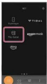






- Tap the "icon of the track you want to reorder, then drag it to the destination.

- To delete a track, tap the editing icon "to switch to editing mode."
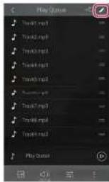
Playback
- Tap the "☐" icon next to the track you want to delete to put in a "√", then when you tap the "☐" icon, the track is deleted from the Play Queue. • To select or release all of the tracks, tap the "☐" icon next to Play Queue.

Playing Back
Playback starts when you select "Play Now" for Play Queue addition, or select the track in the Play Queue service screen.







Connecting a transmitter for playback
When you connect wireless headphones or a wireless speaker transmitter to the ZONE B LINE OUT jacks of this unit, you can play back the same source through the wireless headphones or wireless speakers as in the main room.
Connections
- Use an analog audio cable to connect the ZONE B LINE OUT jacks on this unit to the input jacks on the transmitter.
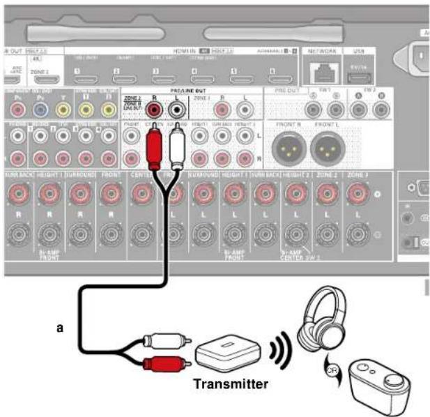
a Analog audio cable


Setting Up
- Press ☐ on the remote controller to display the Home screen, then set "System Setup" - "Speaker" - "Configuration" - "Zone 2 Preout" (→p136) to "Zone B".
Playing Back
-
Press the button on the remote controller and select "Audio" - "Zone B". In the following cases, "Zone B" cannot be selected. - When ZONE 2 is On - When "System Setup" - "Speaker" - "Configuration" - "Zone 2 Preout" on the Home screen is set to "Zone 2" (→p136)
-
Select an audio output destination. Off: Outputs audio only to ZONE A. "A" on the display of the main unit lights up. On (A+B): Outputs audio to both ZONE A and ZONE B. "A" and "B" on the display of the main unit light up. On (B): Outputs audio only to ZONE B. "B" on the display of the main unit lights up.
AB
- Start play on the AV component.
- Adjust the volume on the transmitter, etc., in ZONE B.


Playback
- When "Zone 2 Preout" is set to "Zone B" and "Audio" - "Zone B" at "AV Adjust" is set to "On (A+B)", the output of ZONE A is as shown below.
- When the sound quality is adjusted with the TONE button, the sound quality changes in both ZONE A and ZONE B.
- There will be no effect for the surround back speakers from "System Setup" - "Speaker" - "Distance" (→p139) in the Home screen.
- If "On (A+B)" is selected as an audio output destination, you can select only the "Stereo" listening mode for ZONE A when using the 2.1 ch speaker layout. When using a speaker layout of 3.1 ch or more, you can select only the "Ext. Stereo" listening mode.




Setup
| System Setup 126 | |
| MCACC Pro 157 | |
| Network/Bluetooth | 167 |
| Web Setup 174 | |
| Initial Setup with Auto Start-up Wizard 175 | |
| Pioneer Remote App 181 | |
| Dirac Live | 182 |






System Setup
Use the on-screen displays (OSD) that appear on the TV to make the settings.
Press 🔒 on the remote controller to display the Home screen, then select System Setup with the cursors on the remote controller and press ENTER.
Select the item with the cursor ▲/▼/◄/► buttons of the remote controller and press ENTER to confirm your selection.
Use the cursors ◀ to change the default values.
- To return to the previous screen, press ↩
• To exit the settings, press ↗

Menu list
| Input/Output Assign | TV Out / OSDHDMI Input Change input assignment between the input selectors and HDMI IN jacks. | Make settings for TV output and On-Screen Displays (OSD) that appear on the TV. | p128 |
| p130 | |||
| Video Input | Change input assignment between the input selectors and COMPONENT VIDEO IN jacks and the VIDEO IN jacks. | p130 | |
| Digital Audio Input | Change input assignment between the input selectors and DIGITAL AUDIO IN COAXIAL/OPTICAL jacks. | p130 | |
| Analog Audio Input | Change input assignment between the input selectors and AUDIO IN jacks. | p131 | |
| Input Skip | You can skip inputs to which nothing is connected when selecting them with the INPUT SELECTOR dial on the main unit or with the INPUT SELECT button on the remote controller. | p131 | |
| PERSONAL PRESET Information | Confirm the registered contents of 1 to 3 buttons of PERSONAL PRESET. | p132 | |
| Speaker | Configuration | Change the settings of connection environment of the speakers. | p134 |
| Crossover | Change the settings of crossover frequencies. | p137 | |
| Distance | Set the distance from each speaker to the listening position. | p139 | |
| Channel Level | Adjust the volume level of each speaker. | p140 | |
| Dolby Enabled Speaker | Change the settings of Dolby Enabled Speakers. | p140 | |
| Speaker Virtualizer | The Speaker Virtualizer function can be switched between On and Off. | p140 |







Setup
| Audio Adjust | Dual Mono/Mono | Change the settings of multiplex audio playback. | p141 |
| Dolby Change the setting of when Dolby signals are input. | p141 | ||
| DTS/IMAX Change the setting of when DTS signals are input. | p142 | ||
| LFE Mute Level | Set the low-frequency effect (LFE) level for Dolby Digital series, DTS series, Multichannel PCM, and DSD signals. | p143 | |
| Volume Change the Volume settings. | p143 | ||
| Source | Input Volume Absorber | Adjust the volume level when there are differences in volume level among multiple devices connected to this unit. | p144 |
| Name Edit Set an easy name for each input. | p144 | ||
| Audio Select | Select the priority for input selection when multiple audio sources are connected to one input selector. | p145 | |
| Hardware HDMI Change the settings of the HDMI function. | p146 | ||
| Power Management | Change the settings for the power-save function. | p148 | |
| 12V Trigger A | The 12V TRIGGER OUT A output setting can be set for each input selector. | p150 | |
| 12V Trigger B | The 12V TRIGGER OUT B output setting can be set for each input selector. | p150 | |
| Works with SONOS | Change the settings to connect with the Sonos Connect. | p151 | |
| Multi Zone | Zone 2 | Change the settings for Zone 2. | p152 |
| Zone 3 | Change the settings for Zone 3. | p153 | |
| Remote Play Zone | Change the settings for remote play. | p154 | |
| Miscellaneous | Tuner | Change the settings for Tuner. | p155 |
| Remote ID Change the remote controller ID. | p155 | ||
| Firmware Update | Change the settings for Firmware Update. | p155 | |
| Initial Setup | Make the initial setup from the setup menu. | p156 | |
| Lock | Lock the Setup menu so that the settings cannot be changed. | p156 | |
| Factory Reset | All the settings are restored to factory defaults. | p156 | |



Input/Output Assign
Setup
TV Out / OSD
Make settings for TV output and On-Screen Displays (OSD) that appear on the TV.
☐ HDMI Out (Default Value: MAIN)
Select the HDMI jack to be connected with the TV.
- If devices with different resolutions are connected to HDMI OUT MAIN jack and SUB jack, images are output with the lower resolution.
MAIN When connecting the TV to the HDMI OUT MAIN jack
SUB When connecting the TV to the HDMI OUT SUB jack
MAIN+SUB When connecting to both the MAIN and SUB jacks
☐ Dolby Vision (Default Value: MAIN)
This setting is only necessary if you have set "HDMI Out" to "MAIN+SUB", "Zone 2 HDMI" (→p129) to "Use", and the same video is simultaneously output from multiple HDMI OUT jacks, such as when the same video from ZONE 2 is output from the MAIN or SUB HDMI OUT jacks.
| MAIN To output | Dolby Vision video to a Dolby Vision-supported TV connected to the HDMI OUT MAIN jack |
| SUB To output | Dolby Vision video to a Dolby Vision-supported TV connected to the HDMI OUT SUB jack |
| ZONE 2 To output | Dolby Vision video to a Dolby Vision-supported TV connected to the HDMI OUT ZONE 2 jack |
| Off After selecting | "MAIN" or "SUB", if the video on the TV does not appear correctly |
☐ Upscaling (Default Value: Off)
When using a TV that supports 4K/8K, video signals input at 1080p can be automatically upscaled to 4K/8K for output. Video signals that are input at 4K can also automatically be output as 8K. Note that to output as 8K, set "HDMI 4K/8K Signal Format" (→p129) to "8K Standard" or "8K Enhanced", and you need to connect to a TV that is compatible with the 8K signal format with an HDMI cable.
- If the TV does not support the 4K/8K resolution with the same frequency as the frequency of HDMI input video signals, upscaling to 4K or 8K is not correctly performed. Check the frequency of 4K/8K resolution supported by the TV, and change the resolution of the video signals input from the AV component.
Off When this function is not used
- Select "Off" if your TV does not support 4K/8K.
Auto When this function is used
☐ Super Resolution (Default Value: 2)
When you have set "Upscaling" to "Auto", you can select the degree of video signal correction from "Off" and between "1" (weak) and "3" (strong).






Input/Output Assign
Setup
☐ HDMI 4K/8K Signal Format
Set the 4K/8K signal format input and output by this unit. Set to suit the TV or player connected.
- The corresponding resolution is different depending on the HDMI jack connected. See "Corresponding input resolutions" (→p217) for details.
BD/DVD (Default Value: 4K Enhanced)
GAME (Default Value: 8K Enhanced)
CBL/SAT (Default Value: 4K Enhanced)
STRM BOX (Default Value: 4K Enhanced)
HDMI 5 (Default Value: 4K Enhanced)
HDMI 6 (Default Value: 4K Enhanced)
| 4K Standard When using a High Speed HDMI Cable that supports 10.2 Gbps to connect a TV or player compatible with standard 4K signal formats (4K 30Hz, etc.) |
| 4K Enhanced When using a Premium High Speed HDMI Cable that supports 18 Gbps to connect a TV or player compatible with high-definition 4K signal formats (4K 60Hz, 4K HDR, etc.)• There may be some image disruption depending on the connected component and the HDMI cable. If this occurs, switch to "4K Standard". |
| 8K Standard When using a ULTRA High Speed HDMI Cable that supports 48 Gbps to connect a TV or player compatible with 4K 120Hz, 5K 30Hz, or 8K 30Hz signal formats |
| 8K Enhanced When using an ULTRA High Speed HDMI Cable that supports 48 Gbps to connect a TV or player compatible with 5K 60Hz or 8K 60Hz signal formats |
☐ Zone 2 HDMI (Default Value: Not Use)
Make the setting when you output to the separate room (ZONE 2) TV connected to the HDMI OUT ZONE 2 jack.
| Use Enable this function | |
| Not Use Disable | this functionWhen video and audio via HDMI input are output to ZONE 2, set to "Use". |
☐ OSD Language (Default Value: English)
Select the on-screen display language from the following. (North American and Taiwanese models) English, German, French, Spanish, Italian, Dutch, Swedish (European, Australian and Asian models) English, German, French, Spanish, Italian, Dutch, Swedish, Russian, Chinese
☐ Impose OSD (Default Value: On)
Set whether or not to display information such as volume adjustment or switching of input on the TV screen.
| On | OSD is displayed on the TV• OSD may not be displayed depending on the input signal even if "On" is selected.• When Dolby Vision signals are input, the volume bar changes from blue to magenta. |
| Off | OSD is not displayed on the TV |
☐ Screen Saver (Default Value: 3 minutes)
Set the time to start the screen saver. Select a value from "3 minutes", "5 minutes", "10 minutes" and "Off".






Input/Output Assign
Setup
HDMI Input
Change input assignment between the input selectors and HDMI IN jacks.
☐ BD/DVD (Default Value: HDMI 1 (HDCP 2.3))
GAME (Default Value: HDMI 2 (HDCP 2.3))
CBL/SAT (Default Value: HDMI 3 (HDCP 2.3))
STRM BOX (Default Value: HDMI 4 (HDCP 2.3))
"HDMI 1 (HDCP 2.3)" to "HDMI 4 (HDCP 2.3)":
Assign any HDMI IN jack to each of the input selectors. If you do not assign a jack, select "--". To select an HDMI IN jack already assigned to another input selector, change its setting to "--" first.
Video Input
You can change the COMPONENT VIDEO IN jacks and VIDEO IN jacks allocation settings that are allocated to each input selector. If you do not assign a jack, select "---".
☐ BD/DVD (Default Value: COMPONENT)
GAME (Default Value: ---)
CBL/SAT (Default Value: VIDEO 2)
STRM BOX (Default Value: VIDEO 1)
| COMPONENT | Assign the COMPONENT VIDEO IN jacks to any input selector. |
| VIDEO 1,VIDEO 2 | Assign the VIDEO IN jacks to any input selector. |
Digital Audio Input
Change input assignment between the input selectors and DIGITAL AUDIO IN COAXIAL/OPTICAL jacks. If you do not assign a jack, select "--".
☐ BD/DVD (Default Value: COAXIAL 1)
GAME (Default Value: OPTICAL 3)
CBL/SAT (Default Value: COAXIAL 2)
STRM BOX (Default Value: ---)
CD (Default Value: OPTICAL 1)
TV (Default Value: OPTICAL 2)
TUNER (Default Value: ---) *European, Australian and Asian
models
| COAXIAL 1, COAXIAL 2, OPTICAL 1, OPTICAL 2, OPTICAL 3 | Assign the COAXIAL jacks or OPTICAL jacks to any input selector. |





Input/Output Assign
Setup
■ Analog Audio Input
Change input assignment between the input selectors and AUDIO IN jacks. If you do not assign a jack, select "--".
☐ BD/DVD (Default Value: AUDIO 1)
GAME (Default Value: ---)
CBL/SAT (Default Value: AUDIO 4) *1
STRM BOX (Default Value: AUDIO 3)
CD (Default Value: Balanced)
TV (Default Value: AUDIO 2)
TUNER (Default Value: AUDIO 4) *2
*1 North American and Taiwanese models
*2 European, Australian and Asian models
| AUDIO 1, AUDIO 2, AUDIO 3, AUDIO 4, Balanced | Assign the AUDIO IN jacks to any input selector. |
Input Skip
You can skip inputs to which nothing is connected when selecting them with the INPUT SELECTOR dial on the main unit or with the INPUT SELECT button on the remote controller.
☐ BD/DVD (Default Value: Use)
GAME (Default Value: Use)
CBL/SAT (Default Value: Use)
STRM BOX (Default Value: Use)
HDMI 5 (Default Value: Use)
HDMI 6 (Default Value: Use)
AUX (Default Value: Use)
CD (Default Value: Use)
TV (Default Value: Use)
PHONO (Default Value: Use)
TUNER (Default Value: Use)
NET (Default Value: Use)
USB Front (Default Value: Use)
USB Rear (Default Value: Use)
BLUETOOTH (Default Value: Use)
| Use | Use this input. |
| Skip | Skip this input. |




■ PERSONAL PRESET Information
Confirm the registered contents of 1 to 3 buttons of PERSONAL PRESET. The registered settings are displayed in the list.
☐ Preset (Default Value: Preset 1)
Selects a preset number from among "Preset 1", "Preset 2" and "Preset 3".
(Main)
| Setting Item Default Value Setting | Details | |
| Input Selector | --- | Displays the input selector that has been set. |
| HDMI Out --- Displays the output | destination (HDMI) that has been set. | |
| NetworkService | --- | Displays the set network service and station name. |
| Band/Station | --- | Displays the set "AM" or "FM" band and the Preset Name for the station.* North American and Taiwanese models |
| Listening Mode --- Displays the listening mode that has been set. | ||
| Volume | --- | Displays the volume level that has been set. (Upper limit "0.0 dB") |
| Multi Zone | --- | Displays the output destination (Multi Zone) that has been set. |
| MCACC Memory | --- Displays the number of the set MCACC Memory. | |
| MCACC EQ | --- | Displays the status of the set MCACC EQ. |
| Standing Wave | --- | Displays the status of the set Standing Wave setting. |
| Phase Control --- Displays the status of the set Phase Control. | ||
| AutoPhaseControlPlus | --- | Displays the setting value of the set Auto Phase Control Plus. |
Setting Item Default Value Setting Details
| Sound Delay | --- | Displays the setting value of the set Sound Delay. |
- "Band/Station" is displayed only when the input selector is set to "TUNER".
- "Station" is displayed only when the input selector is set to "TUNER" or "NET".
- "Network Service" is displayed only when the input selector is set to "NET".
- Preset Name of "Band/Station" (only when the input selector is set to "TUNER") is displayed with the name set by "Source" - "Name Edit". If the name is not set, the frequency of the radio station is displayed instead.


Input/Output Assign
Setup
(Zone 2)
| Setting Item Default Value Setting Details | ||
| Input Selector | --- | Displays the input selector that has been set. |
| NetworkService | --- | Displays the network service that has been set. |
| Band | --- | Displays the band, "AM" or "FM" that has been set.* North American and Taiwanese models |
| Station --- Displays the preset name of the radio station that has been set. | ||
- "Band" is displayed only when the input selector is set to "TUNER".
- "Station" is displayed only when the input selector is set to "TUNER" or "NET".
- "Network Service" is displayed only when the input selector is set to "NET".
- Preset Name of "Station" (only when the input selector is set to "TUNER") is displayed with the name set by "Source" - "Name Edit". If the name is not set, the frequency of the radio station is displayed instead.
(Zone 3)
| Setting Item Default Value Setting Details | ||
| Input Selector | --- | Displays the input selector that has been set. |
| NetworkService | --- | Displays the network service that has been set. |
| Band | --- | Displays the band, "AM" or "FM" that has been set.* North American and Taiwanese models |
| Station --- Displays the preset name of the radio station that has been set. | ||
- "Band" is displayed only when the input selector is set to "TUNER".
- "Station" is displayed only when the input selector is set to "TUNER" or "NET".
- "Network Service" is displayed only when the input selector is set to "NET".
- Preset Name of "Station" (only when the input selector is set to "TUNER") is displayed with the name set by "Source" - "Name Edit". If the name is not set, the frequency of the radio station is displayed instead.



SpeakerSpeaker
Setup
Configuration
Change the settings of connection environment of the speakers.
- If the settings for "Speaker Channels", "Subwoofer", "Height 1 Speaker", or "Height 2 Speaker" have been changed, the Dirac Live (→p178, p182) measurement results are deleted.
☐ Speaker Channels (Default Value: 7.1.4 ch)
Select "2.1 ch", "3.1 ch", "4.1 ch", "5.1 ch", "6.1 ch", "7.1 ch", "2.1.2 ch", "3.1.2 ch", "4.1.2 ch", "5.1.2 ch", "6.1.2 ch", "7.1.2 ch", "4.1.4 ch", "5.1.4 ch", "6.1.4 ch", or "7.1.4 ch" to suit the number of speaker channels connected.
Subwoofer Preout (Default Value: SW 1 & SW 2)
Set whether a powered subwoofer is connected or not.
No When a powered subwoofer is not connected
SW 1 When connecting 1 or 2 powered subwoofers to the SW1 terminal
SW 1 & SW 2 When connecting 1 or 2 powered subwoofers to the SW1 terminal and SW 2 terminal
- Different signals are output from the SW1 and SW2 terminals. The volume level can also be set separately. (→p140)
- The same signals are output from "A" and "B" of the SW1 terminal. The SW2 terminal also has the same specification.
☐ Passive Subwoofer (Default Value: No)
Set whether a passive subwoofer is connected or not.
No When a passive subwoofer is not connected
1 ch When 1 passive subwoofer is connected • Connect to the HEIGHT 2 (SW1) jack.
2 ch When 2 passive subwoofers are connected • Connect the first to the HEIGHT 2 (SW 1) jack and the second to the HEIGHT 2 (SW 2) jack.
- This setting cannot be selected under the following conditions.
- "Bi-Amp" is set to "Front/Center"
- "Zone Speaker" is set to "Zone 2/Zone 3"
- "Speaker Channels" is set to "6.1.4 ch" or "7.1.4 ch"
- "Speaker Channels" is set to "6.1.2 ch", "7.1.2 ch", "4.1.4 ch", or "5.1.4 ch" and "Zone Speaker" is set to "Zone 2" or "Bi-Amp" is set to "Front"
- "Speaker Channels" is set to "2.1.2 ch", "3.1.2 ch", "4.1.2 ch", or "5.1.2 ch" and "Bi-Amp" is set to "Front"
- "Speaker Channels" is set to "6.1 ch" or "7.1 ch" and "Zone Speaker" is set to "Zone 2" and "Bi-Amp" is set to "Front"






Speaker
Setup
☐ Height 1 Speaker (Default Value: Top Front)
Set the speaker type if height speakers are connected to the HEIGHT 1 terminals.
Select "Top Middle", "Top Rear", "Rear High", "Dolby Speaker (Front)", "Dolby Speaker (Surr)", "Dolby Speaker (Back)", "Front High" or "Top Front" according to the type and layout of the connected speakers.
- The setting cannot be selected if "Bi-Amp" is set to "Front/Center".
- When two sets of height speakers are being used, "Top Rear", "Rear High", "Dolby Speaker (Surr)", and "Dolby Speaker (Back)" cannot be selected.
- "Dolby Speaker (Surr)" and "Dolby Speaker (Back)" can only be selected when surround speakers or surround back speakers are being used, respectively. You can check speakers that you are using on the figure displayed in "Speaker Channels".
- If an item cannot be selected even though connection is correct, check that the settings in "Speaker Channels" matches the number of connected channels.
☐ Height 2 Speaker (Default Value: Top Rear)
Set the speaker type if height speakers are connected to the HEIGHT 2 terminals.
Select "Front High", "Top Front", "Top Middle", "Top Rear", "Rear High", "Dolby Speaker (Front)", "Dolby Speaker (Surr)" or "Dolby Speaker (Back)" according to the type and layout of the connected speakers. However, the options selectable for the "Height 1 Speaker" are as follows.
- If "Height 1 Speaker" is set to "Front High": Select from "Top Middle", "Top Rear", "Rear High", "Dolby Speaker (Surr)" or "Dolby Speaker (Back)".
- If "Height 1 Speaker" is set to "Top Front" or "Dolby Speaker (Front)": Select from "Top Rear", "Rear High", "Dolby Speaker (Surr)" or "Dolby Speaker (Back)".
- If "Height 1 Speaker" is set to "Top Middle": Fixed to "Rear High".
- "Dolby Speaker (Surr)" and "Dolby Speaker (Back)" can only be selected when surround speakers or surround back speakers are being used, respectively. You can check speakers that you are using on the figure displayed in "Speaker Channels".
- If an item cannot be selected even though connection is correct, check that the settings in "Speaker Channels" matches the number of connected channels.







Speaker
Setup
☐ Zone Speaker (Default Value: No)
Set whether ZONE 2 speakers and ZONE 3 speakers are being used.
- This setting cannot be selected when "Zone 2 Preout" is set to "Zone B".
| No When neither ZONE 2 speakers nor ZONE 3 speakers are used |
| Zone 2 When ZONE 2 speakers are used |
| Zone 2/Zone 3 When both ZONE 2 speakers and ZONE 3 speakers are used |
☐ Zone 2 Preout (Default Value: Zone 2)
Set an output destination of the audio output from ZONE 2 PRE/LINE OUT / ZONE B LINE OUT jack.
- This setting is fixed to "Zone 2" when "Zone Speaker" is set to "Zone 2" or "Zone 2/Zone 3".
| Zone 2 When connecting an integrated amplifier in a separate room (ZONE 2) |
| Zone B When connecting an integrated amplifier, transmitter of wireless headphones, etc. to ZONE B |
Bi-Amp (Default Value: No)
Set whether the speakers are bi-amp connected.
- You cannot select a setting other than "No" or "Front" when using ZONE speakers.
| No When no speakers are bi-amp connected | |
| Front When only | front speakers are bi-amp connectedThis setting cannot be selected under the following conditions.“Speaker Channels” is set to "6.1.4 ch" or "7.1.4 ch”“Speaker Channels” is set to "6.1.2 ch", "7.1.2 ch", "4.1.4 ch", or "5.1.4 ch" and "Zone Speaker" is set to "Zone 2" or "Zone 2/Zone 3”— "Speaker Channels" is set to "6.1 ch", "7.1 ch", or "2.1.2 ch" to "5.1.2 ch" and "Zone Speaker" is set to "Zone 2/Zone 3" |
| Front/Center | When front speakers and the center speaker are bi-amp connectedThis can only be selected when you have set "Speaker Channels" to "3.1 ch", "5.1 ch", or "7.1 ch". |
☐ Speaker Impedance (Default Value: 6 ohms or above)
Set the impedance (Ω) of the connected speakers.
- For impedance, check the indications on the back of the speakers or their instruction manual.
| 4ohms | When any of the connected speakers have 4 Ω or more to less than 6 Ω impedance |
| 6ohmsorabove | When the connected speakers all have 6 Ω or more impedance |






Speaker
Setup
Crossover
Set what number of Hz in the low frequency range is output from each speaker and what should be output from the subwoofer. When a subwoofer is not to be used, set to "Full Band" so that the bass is output from the speakers.
- When Dirac Live Bass Control ( p182 ) is used, the crossover frequency setting made here is not available. Set using Pioneer Remote App ( p181 ).
☐ Dirac Live Bass Control (Default Value: Off)
Use the Dirac Live Bass Control to adjust the crossover frequency.
| On When using | Dirac Live Bass Control. This can be selected when Dirac Live Bass Control measurements are performed. |
| Off When this function is to not be used | |
☐ Setting Type (Default Value: Common)
Set the crossover frequency to suit the speakers.
| Common Set a | common crossover frequency for each speaker channel. Set "Small" or "Large" for each speaker channel. |
| Individual Set in | individual crossover frequencies for each speaker channel. You can set starting at 40Hz, referencing the crossover frequency for each speaker. |
Front (Default Value: Small/80 Hz)
Center (Default Value: Small/80 Hz)
Height 1 (Default Value: Small/80 Hz)
Height 2 (Default Value: Small/80 Hz)
Surround (Default Value: Small/80 Hz)
Surround Back (Default Value: Small/80 Hz)
Crossover (Default Value: 80 Hz)
LPF of LFE (Default Value: 120 Hz)
Double Bass (Default Value: Off)
- This setting is disabled when the IMAX sound mode has been applied. However, when the "IMAX User Setting" (→p142) is "Manual" (default value is Auto), it is enabled.
Front:
When the "Setting Type" is "Common" (→p137)
Set according to the speakers to be used.
"Small": When not using floor standing front speakers.
"Large": When using floor standing front speakers.
- If "Configuration" - "Subwoofer" is set to "No", "Front" will be fixed to "Large" and the low pitched range of the other channels will be output from the front speakers. Refer to the instruction manual of your speakers to make the setting.
When the "Setting Type" is "Individual" (→p137)
Set how many Hz for the range of each channel, with crossover frequencies selectable between "40 Hz" and "200 Hz".
"Full Band": Full band will be output.
- If the setting for "Configuration" - "Subwoofer Preout" or "Passive Subwoofer" is "No", the setting for "Front" is fixed to "Full Band" and the low frequency range for each of the other speakers is output from the front speakers. Refer to the instruction manual of your speakers to make the setting.







Center, Height 1, Height 2, Surround:
When the "Setting Type" is "Common" (→p137)
Set according to the speakers to be used.
"Small": When speaker where the speaker diameter is 16 cm or less are to be used.
"Large": When speaker where the speaker diameter is larger than 16 cm are to be used.
- When "Front" is set to "Small", this is set to "Small".
- If an item cannot be selected even though connection is correct, check that the settings in "Configuration" - "Speaker Channels" matches the number of connected channels.
When the "Setting Type" is "Individual" (→p137)
Set how many Hz for the range of each channel, with crossover frequencies selectable between "40 Hz" and "200 Hz".
"Full Band": Full band will be output.
- "Full Band" can be selected only when "Front" is set to "Full Band".
- If an item cannot be selected even though connection is correct, check that the settings in "Configuration" - "Speaker Channels" matches the number of connected channels.
Surround Back:
When the "Setting Type" is "Common" (→p137)
Set according to the speakers to be used.
"Small": When speaker where the speaker diameter is 16 cm or less are to be used.
"Large": When speaker where the speaker diameter is larger than 16 cm are to be used.
- When "Surround" is set to "Small", this is set to "Small".
- If an item cannot be selected even though connection is correct, check that the settings in "Configuration" - "Speaker Channels" matches the number of connected channels.
When the "Setting Type" is "Individual" (→p137)
Set how many Hz for the range of each channel, with crossover frequencies selectable between "40 Hz" and "200 Hz".
"Full Band": Full band will be output.
- "Full Band" can be selected only when "Surround" is set to "Full Band".
- If an item cannot be selected even though connection is correct, check that the settings in "Configuration" - "Speaker Channels" matches the number of connected channels.
Crossover(\*):
When there are speakers that have been set to "Small", set the Hz under which you would like other speakers to play bass, and also set Hz under which you would like the LFE (low frequency effect) to play the bass.
The value from "50 Hz" to "200 Hz" can be set.
* Can be selected when the "Setting Type" is "Common". (→p137)
LPF of LFE(\*):
Set the low-pass filter for LFE (low-frequency effect) signals in order to pass only the lower frequency signals than the set value, and thus cancel unwanted noises. The low-pass filter is effective only on sources with LFE channel.
The value from "80 Hz" to "120 Hz" can be set.
"Off": When this function is to not be used
* Can be selected when the "Setting Type" is "Individual". (→p137)







Speaker
Setup
Double Bass:
This can only be selected when the setting for "Configuration" - "Subwoofer Preout" is "SW 1" or "SW 1 & SW 2", or the setting for "Passive Subwoofer" is "1ch" or "2ch", and the "Front" setting is "Full Band".
Boost bass output by feeding bass sounds from the front left and right speakers and the center speaker to the subwoofer.
"On": Bass output will be boosted
"Off": Bass output will not be boosted
- The setting will not automatically be configured even if you performed Full Auto MCACC or Dirac Live.
Distance
Set the distance from each speaker to the listening position.
☐ Front Left (Default Value: 10.0 ft/3.00 m)
Center (Default Value: 10.0 ft/3.00 m)
Front Right (Default Value: 10.0 ft/3.00 m)
Height 1 Left (Default Value: 10.0 ft/3.00 m)
Height 1 Right (Default Value: 10.0 ft/3.00 m)
Height 2 Left (Default Value: 10.0 ft/3.00 m)
Height 2 Right (Default Value: 10.0 ft/3.00 m)
Surround Right (Default Value: 10.0 ft/3.00 m)
Surr Back Right (Default Value: 10.0 ft/3.00 m)
Surr Back Left (Default Value: 10.0 ft/3.00 m)
Surround Left (Default Value: 10.0 ft/3.00 m)
Subwoofer 1 (Default Value: 10.0 ft/3.00 m)
Subwoofer 2 (Default Value: 10.0 ft/3.00 m)
- Default values vary depending on the regions.
- The unit of distance can be changed by pressing the MODE button on the remote controller. When the unit is set as "feet", you can set between 0' 0" 1/2 and 30' 0" in increments of 1/2. When using the unit "meter", the setting is available in increments of 0.01 m from 0.01 m to 9.00 m.
- When measurements are made using Dirac Live (→p178, p182), units are displayed as "msec" and the value cannot be changed.
(Height 1 Left, Height 1 Right, Height 2 Left, Height 2 Right, Surr Back Right, Surr Back Left):
- Depending on the use of the ZONE speakers, it may not be possible to select this setting.







Speaker
Setup
Channel Level
Adjust the volume level of each speaker.
☐ Front Left (Default Value: 0.0 dB)
Center (Default Value: 0.0 dB)
Front Right (Default Value: 0.0 dB)
Height 1 Left (Default Value: 0.0 dB)
Height 1 Right (Default Value: 0.0 dB)
Height 2 Left (Default Value: 0.0 dB)
Height 2 Right (Default Value: 0.0 dB)
Surround Right (Default Value: 0.0 dB)
Surr Back Right (Default Value: 0.0 dB)
Surr Back Left (Default Value: 0.0 dB)
Surround Left (Default Value: 0.0 dB)
Subwoofer 1 (Default Value: 0.0 dB)
Subwoofer 2 (Default Value: 0.0 dB)
Select a value between "-12.0 dB" and "+12.0 dB" ("-15.0 dB" and "+12.0 dB" for Subwoofer) (in 0.5 dB increments). A test tone will be output each time you change the value. Select the desired level.
(Height 1 Left, Height 1 Right, Height 2 Left, Height 2 Right, Surr Back Right, Surr Back Left):
- Depending on the use of the ZONE speakers, it may not be possible to select this setting.
■ Dolby Enabled Speaker
Change the settings of Dolby Enabled Speakers.
- This setting can be selected when "Configuration" - "Height 1 Speaker" / "Height 2 Speaker" is set to "Dolby Speaker".
☐ Distance from the ceiling (Default Value: 6.0 ft/1.80 m)
Set the distance between the Dolby Enabled Speaker and the ceiling. Select between "0.1 ft"/"0.03 m" and "15.0 ft"/"4.50 m" ("0.1 ft"/"0.03 m" units).
- The unit of distance (ft/m) is displayed using the unit selected for the "Distance" setting.
☐ Reflex Optimizer (Default Value: Off)
You can enhance the reflection effect of Dolby Enabled Speakers from the ceiling.
- The function is not effective if the listening mode is Pure Direct.
- The function is not effective if "Dirac Live" (→p93) has been enabled.
| Off | When this function is not used |
| On | When this function is used |
Speaker Virtualizer
The Speaker Virtualizer function can be switched between On and Off.
☐ Speaker Virtualizer (Default Value: On)
| On | The listening mode with virtual speaker effect such as F.S.Surround can be selected. |
| Off | The listening mode with virtual speaker effect such as F.S.Surround cannot be selected. |





Audio Adjust
Setup
Dual Mono/Mono
Change the settings of multiplex audio playback.
Dual Mono (Default Value: Main)
Set the audio channel or language to be output when playing multiplex audio or multilingual broadcasts, etc.
- For multiplex audio broadcasts, pressing the i button on the remote controller will display "1+1" on the main unit's display.
Main Main channel only
Sub Sub channel only
Main / Sub Main and sub channels will be output at the same time.
☐ Mono Input Channel (Default Value: Left + Right)
Set the input channel when playing back analog or 2 ch PCM signals in the Mono listening mode.
Left Left channel only
Right Right channel only
Left + Right Left and right channels
Dolby
Change the setting of when Dolby signals are input.
☐ Loudness Management (Default Value: On)
When playing Dolby TrueHD, enable the dialog normalization function which keeps the volume of dialog at a certain level. Note that when this setting is "Off", the Midnight function that allows you to enjoy surround at low volumes is fixed to "Off" when playing Dolby Digital Plus/Dolby TrueHD.
On When this function is used
Off When this function is not used
☐ Center Spread (Default Value: Off)
Adjust the width of the front sound field created when playing back with the Dolby Audio - Surr listening mode.
- Depending on the speaker settings, "Off" is applied.
On The sound field is spread to left and right.
Off The sound field is centralized.



Audio Adjust
Setup
DTS/IMAX
Change the setting of when DTS signals are input.
☐ Dialog Control (Default Value: 0 dB)
You can increase the volume of dialog portion of the audio up to 6 dB by 1 dB
step so that you can hear the dialog easily in noisy atmosphere.
• This cannot be set for content other than DTS:X.
- Depending on the content, this function may not be selected.
IMAX Mode (Default Value: Auto)
Set the IMAX sound mode.
| Auto IMAX sound mode is automatically applied when IMAX content is detected. |
| On In cases when this unit is unable to recognize IMAX content, you can apply the IMAX sound mode by turning this setting "On". |
| Off Disable this function |
☐ IMAX User Setting (Default Value: Auto)
When playing IMAX content with the IMAX sound mode, select whether to automatically apply the speaker setting recommended by IMAX or to set it manually.
- This cannot be selected when the "IMAX Mode" is "Off".
| Auto To use the speaker setup recommended by IMAX. |
| Manual To manually set "IMAX Bass Feeding" and "IMAX LFE Mute Level". |
IMAX Bass Feeding (Default Value: On)
Set the route for the bass component of the audio.
- This cannot be selected when the "IMAX User Setting" is "Auto".
On The bass component of each channel is output according to the crossover settings (→p137).
Off Only the LFE signal is output.
☐ IMAX LFE Mute Level (Default Value: 0 dB)
- This cannot be selected when the "IMAX User Setting" is "Auto".
You can set the volume for the LFE when IMAX signals are being input. Select "-∞ dB" or a value between "0 dB" and "-20 dB".





Audio Adjust
Setup
LFE Mute Level
Set the low-frequency effect (LFE) level for Dolby Digital series, DTS series, Multichannel PCM, and DSD signals.
☐ LFE Mute Level (Default Value: 0 dB)
Select the low-frequency effect (LFE) level of each signal from "0 dB" to "-∞ dB". If the low-frequency effect sound is too strong, select "-20 dB" or "-∞ dB".
Volume
Change the Volume settings.
Volume Display (Default Value: Absolute)
Switch the volume display between the absolute value and relative value. The absolute value 82.0 is equivalent to the relative value 0.0 dB.
| Absolute Absolute value such as "0.5" and "99.5"• If the absolute value is set to 82.0, "82.0 Ref" will appear on the display. |
| Relative Relative value such as "-81.0 dB" and "+18.0 dB" |
☐ Mute Level (Default Value: -∞ dB)
Set the volume lowered from the listening volume when muting is on. Select a value from "-∞ dB", "-40 dB" and "-20 dB".
☐ Volume Limit (Default Value: Off)
Set the maximum value to prevent the volume from becoming too loud. Select a value from "Off", "-32 dB" to "+17 dB".
Power On Level (Default Value: Last)
Set the volume level of when the power is turned on. Select a value from "Last" (Volume level before entering standby mode), "-∞ dB", and "-81.5 dB" to "+18.0 dB". • You cannot set a higher value than that of "Volume Limit".
☐ Headphone Level (Default Value: 0.0 dB)
Adjust the output level of headphones. Select a value between "-12.0 dB" and "+12.0 dB".






Source
Setup
■ Input Volume Absorber
Adjust the volume level when there are differences in volume level among multiple devices connected to this unit. Select the input selector to make the setting.
☐ Input Volume Absorber (Default Value: 0.0 dB)
Select a value between "-12.0 dB" and "+12.0 dB". Set a negative value if the volume of the target device is larger than the others and a positive value if smaller. To check the audio, play back the connected device. - This function is not effective in Zone 2/zone 3.
Name Edit
Set an easy name for each input. The set name appears on the main unit's display. Select the input selector to make the setting.
☐ Name Edit (Default Value: Input name)
- Select a character or symbol with the cursors, and press ENTER. Repeat this operation to input up to 10 characters.
"A/a": Switches between upper and lower cases. (Pressing MODE on the remote controller also toggles between upper and lower cases)
"←" "→": Moves the cursor in the arrow direction.
"Removes a character on the left of the cursor.
"Enter a space. - Pressing CLEAR on the remote controller will remove all the input characters.
- After inputting, select "OK" with the cursors, and press ENTER. The input name will be saved.
To restore the name to the default value, press CLEAR on the remote controller on the input screen. Then while nothing is entered, select "OK", and press ENTER. - To name a preset radio station, press TUNER on the remote controller, select AM/FM, and select the preset number. (North American and Taiwanese models)
- This cannot be set if the "NET" or "BLUETOOTH" input is selected.






Source
Setup
Audio Select
Select the priority for input selection when multiple audio sources are connected to one input selector, such as connections to both the "BD/DVD" HDMI IN jack and the "BD/DVD" AUDIO IN jack. The setting can be separately set to each input selector button. Select the input selector to configure. Note that there are some default values you cannot change.
☐ BD/DVD (Default Value: HDMI)
GAME (Default Value: HDMI)
CBL/SAT (Default Value: HDMI)
STRM BOX (Default Value: HDMI)
AUX (Default Value: HDMI)
CD (Default Value: COAXIAL)
TV (Default Value: OPTICAL)
PHONO (Default Value: Analog)
| ARC When giving priority to input signal from ARC compatible TV. This item can be selected only when "Hardware" - "HDMI" - "Audio Return Channel (eARC supported)" is set to "On" and also the "TV" input is selected. | |
| HDMI | When giving priority to input signal from HDMI IN jacksThis item can be selected only when the input to be set is assigned to the HDMI jack in the "Input/Output Assign" - "HDMI Input" setting. |
| COAXIAL | When giving priority to input signal from DIGITAL AUDIO IN COAXIAL jacksThis item can be selected only when the input to be set is assigned to the COAXIAL jack in the "Input/Output Assign" - "Digital Audio Input" setting. |
| OPTICAL | When giving priority to input signal from DIGITAL AUDIO IN OPTICAL jacksThis item can be selected only when the input to be set is assigned to the OPTICAL jack in the "Input/Output Assign" - "Digital Audio Input" setting. |
| Analog | When giving priority to the input signal from AUDIO IN jacks• This item can be selected only when the input to be set is assigned to the AUDIO IN jack in the "Input/Output Assign" - "Analog Audio Input" setting. |
☐ Fixed PCM (Default Value: Off)
Select whether to fix input signals to PCM (except multi-channel PCM) when you select "HDMI", "COAXIAL", or "OPTICAL" in the "Audio Select" setting. Set this item to "On" if noise is produced or truncation occurs at the beginning of a track when playing PCM sources. Select "Off" normally.
Each time the "Audio Select" setting is changed, the setting is restored to "Off".
- The setting cannot be changed when "TUNER"(*), "NET", "USB", or "BLUETOOTH" input is selected.
* North American and Taiwanese models





Hardware
Setup
HDMI
Change the settings of the HDMI function.
☐ HDMI CEC (Default Value: On)
Setting this to "On" enables the input selection link and other link functions with HDMI-connected CEC-compatible device.
When this setting is changed, turn off and then on again the power of all connected devices.
- Depending on the TV to use, a link setting may be required on the TV.
- This function is effective only when the device is connected to the HDMI OUT MAIN jacks.
- Setting this to "On" and closing the operation screen will display the name of the connected CEC-compatible device and "CEC On" on the main unit's display.
- When this function is set to "On", the power consumption in standby state increases, however, the increase in power consumption is minimized by automatically entering the HYBRID STANDBY mode where only the essential circuits operate.
- If you operate the MASTER VOLUME dial on the main unit when this setting is "On" and audio is output from the TV speakers, audio will be output also from the speakers connected to this unit. To output audio from only either of them, change the setting of this unit or TV, or reduce the volume of this unit.
- If abnormal behavior is observed when this is set to "On", set it to "Off".
- If a connected device is not CEC-compatible, or if you are not sure whether it is compatible, set it to "Off".
On When this function is used
Off When this function is not used
☐ HDMI Standby Through (Default Value: Auto (Eco))
When this is set to anything other than "Off", you can play the video and audio of an HDMI-connected player on the TV even if the unit is in standby mode. Also, only "Auto" and "Auto (Eco)" can be selected if "HDMI CEC" is set to "On". If you select anything else, set "HDMI CEC" to "Off".
- When this function is set to a value other than "Off", the power consumption in standby state increases, however, the increase in power consumption is minimized by automatically entering the HYBRID STANDBY mode where only the essential circuits operate.
- To play a non-CEC compliant player on the TV, turn the unit on and switch the input.
- When using a CEC-compliant TV, you can reduce the power consumption in standby mode by selecting "Auto (Eco)".
Off When this function is not used
| BD/DVD,GAME,CBL/SAT,STRM BOX,HDMI 5,HDMI 6,AUX,TUNER* | For example, if you select "BD/DVD", you can play the equipment connected to the "BD/DVD" jack on the TV even if the unit is in standby mode. Select this setting if you have decided which player to use with this function.*European, Australian and Asian models |
| Last You can play on the TV the video and audio of the input selected immediately before the unit is switched to standby. | |
| Auto,Auto (Eco) | Select one of these settings when you have connected equipment that conforms to the CEC standard. You can play the video and audio of the input selected on the TV, irrespective of what input was selected immediately prior to the unit being switched to standby, using the CEC link function. |






Hardware
Setup
☐ Audio TV Out (Default Value: Auto)
You can enjoy audio through the speakers of the TV while this unit is on.
- This setting is fixed to "Auto" if you have set "Input/Output Assign" - "TV Out/OSD" - "HDMI Out" or "HDMI" - "HDMI Out" in "AV Adjust" to "MAIN" or "MAIN+SUB" and "HDMI CEC" is set to "On". If you change this setting, set "HDMI CEC" to "Off".
- Listening mode cannot be changed while "Audio TV Out" is set to "On" and audio is being output from the TV.
- Depending on your TV or input signal of the connected device, audio may not be output from the TV even if this is set to "On". In such a case, audio is output from the speakers of the unit.
- Audio is output from this unit if you operate the MASTER VOLUME dial on this unit when audio that is input to this unit is output from your TV speakers. If you do not want to output audio, change the setting of this unit or TV, or reduce the volume of this unit.
On When this function is used
Off When this function is not used
| Auto When the | "HDMI Out" setting is "MAIN" or "MAIN+SUB" and the "HDMI CEC" setting is "On", the setting is fixed to "Auto". With "Auto", when audio is output from the TV speakers, audio is not output from the speakers of this unit, and when audio is output from the speakers of this unit, audio is not output from the TV speakers.· If the HDMI CEC setting is off on the TV, there may be audio output from both the TV speakers and the speakers of this unit. |
☐ Audio Return Channel (eARC supported) (Default Value: On)
You can enjoy the sound of an HDMI-connected ARC-compatible TV or eARC-compatible TV through the speakers connected to the unit.
On When enjoying the TV sound through the speakers connected to the unit
Off When the ARC function or eARC function is not used
☐ Auto Delay (Default Value: On)
Automatically corrects desynchronization between the video and audio signals based on the information from the HDMI Lip-Sync-compatible TV.
On When enabling the automatic correction function
Off When not using the automatic correction function





Power Management
Change the settings for the power-save function.
☐ Sleep Timer (Default Value: Off)
| 30 minutes,60 minutes,90 minutes | You can allow the unit to enter standby automatically when the specified time elapsed. Select a value from "30 minutes", "60 minutes" and "90 minutes". |
| Off Does not turn the unit to standby automatically. | |
☐ Auto Standby (Default Value: On/Off)
This setting allows the unit to enter standby mode automatically after 20 minutes of inactivity without any video or audio input. (When "USB Power Out at Standby" or "Network Standby" is enabled, the unit enters the HYBRID STANDBY mode which minimizes the increase in power consumption.)
- Default values vary depending on the regions.
| On The unit will automatically enter standby mode ("AUTO STBY" will light).• "Auto Standby" is displayed on the main unit's display and TV screen 30 seconds before entering standby mode.• "Auto Standby" does not work when Zone 2/Zone 3 is active. |
| Off The unit will not automatically enter standby mode. |
☐ Auto Standby in HDMI Standby Through (Default Value: On/Off)
Enable or disable "Auto Standby" while "HDMI Standby Through" is on.
- Default values vary depending on the regions.
| On The setting will be enabled. |
| This setting cannot be set to "On" if "Auto Standby" and"HDMI Standby Through" are set to "Off". |
| Off The setting will be disabled. |
☐ USB Power Out at Standby (Default Value: Off)
Devices connected to the USB port (5 V/1 A) on the rear of the unit can be supplied with electricity even when this unit is in standby mode when this function is "On".
- Supply of power to USB devices in the standby mode is not supported for the USB port on the front panel.
- When this function is set to "On", the power consumption in standby state increases, however, the increase in power consumption is minimized by automatically entering the HYBRID STANDBY mode where only the essential circuits operate.


Hardware
Setup
☐ Network Standby (Default Value: On)
When this function is set to "On", the network function works even in standby state, and you can turn on the power of the unit via network using an application such as Pioneer Remote App that can control this unit.
- When this function is set to "On", the power consumption in standby state increases, however, the increase in power consumption is minimized by automatically entering the HYBRID STANDBY mode where only the essential circuits operate.
Note that even if this function is set to "Off", when any of the HDMI CEC ( p146), HDMI Standby Through ( p146), USB Power Out at Standby ( p148) and Bluetooth Wakeup ( p149) functions is enabled, this function will be in "On" state regardless of the setting.
- When connection to the network is lost, "Network Standby" may be disabled to reduce power consumption. In such a case, turn the unit on by using the power button on the remote controller or main unit.
Bluetooth Wakeup (Default Value: Off)
This function wakes up the unit on standby by connecting a BLUETOOTH enabled device. This is effective when "Bluetooth" - "Bluetooth Receiver" is set to "On".
| On When this function is usedWhen this function is set to "On", the power consumption in standby state increases, however, the increase in power consumption is minimized by automatically entering the HYBRID STANDBY mode where only the essential circuits operate. |
| Off When this function is not usedThis setting is fixed to "Off" if "Network/Bluetooth" - "Bluetooth" - "Bluetooth Receiver" is set to "Off".This setting is also fixed to "Off" if "Network/Bluetooth" - "Bluetooth" - "Bluetooth Receiver" - "Auto Input Change" is set to "Off". |
- Wait for a while if "Network Standby" and "Bluetooth Wakeup" cannot be selected. It can be selected when the network function is activated.




12V Trigger A
Set when outputting the control signal (maximum 12 V/100 mA) through the 12V TRIGGER OUT A jack. Different settings can be set for each input selector. You can enable power link operation when you connect the unit and the external devices equipped with 12V trigger input jack.
☐ BD/DVD (Default Value: Off)
GAME (Default Value: Off)
CBL/SAT (Default Value: Off)
STRM BOX (Default Value: Off)
HDMI 5 (Default Value: Off)
HDMI 6 (Default Value: Off)
AUX (Default Value: Off)
CD (Default Value: Off)
TV (Default Value: Off)
PHONO (Default Value: Off)
TUNER (Default Value: Off)
NET (Default Value: Off)
USB Front (Default Value: Off)
USB Rear (Default Value: Off)
BLUETOOTH (Default Value: Off)
Set the 12V trigger output setting to each input.
| Off | When the control signal is not output |
| Main | When controlling the power of external devices linked to the input selection in the main room |
| Zone 2 | When controlling the power of external devices linked to the input selection in ZONE 2 |
| Zone 3 | When controlling the power of external devices linked to the input selection in ZONE 3 |
12V Trigger B
Set when outputting the control signal (maximum 12 V/25 mA) through the 12V TRIGGER OUT B jack. Different settings can be set for each input selector. You can enable power link operation when you connect the unit and the external devices equipped with 12V trigger input jack.
☐ BD/DVD (Default Value: Off)
GAME (Default Value: Off)
CBL/SAT (Default Value: Off)
STRM BOX (Default Value: Off)
HDMI 5 (Default Value: Off)
HDMI 6 (Default Value: Off)
AUX (Default Value: Off)
CD (Default Value: Off)
TV (Default Value: Off)
PHONO (Default Value: Off)
TUNER (Default Value: Off)
NET (Default Value: Off)
USB Front (Default Value: Off)
USB Rear (Default Value: Off)
BLUETOOTH (Default Value: Off)
Set the 12V trigger output setting to each input.
| Off | When the control signal is not output |
| Main | When controlling the power of external devices linked to the input selection in the main room |
| Zone 2 | When controlling the power of external devices linked to the input selection in ZONE 2 |
| Zone 3 | When controlling the power of external devices linked to the input selection in ZONE 3 |


Hardware
Setup
Works with SONOS
Change the settings to connect with the Sonos Connect.
(SONOS-1/SONOS-2/SONOS-3)
☐ Input Selector (Default Value: Off)
Select the input selector to which the Sonos Connect is connected.
- Selecting "Off" disables the interlock function with Sonos.
☐ Connected Device (Default Value: -)
Displays the Sonos Connect connected to the same network as the network of this unit. Press the ENTER button to select the connected Sonos Connect.
- Products (e.g. Play:3 unequipped with an output terminal) other than the Sonos Connect are also displayed in the device list and selectable. In that case, when playback on the Sonos side starts, the input is switched, however, audio is not output. Select the room name of the connected Sonos Connect.
- Up to 32 devices can be displayed on the Sonos product list screen. If you cannot find the Sonos Connect to be interlocked, return to the previous screen, turn off the product you do not want to interlock, and try again.
- To use this function, set "Input Selector" beforehand.
☐ Output Zone (Default Value: Main)
Select the zone where you want to listen to the music.
- To use this function, set "Input Selector" beforehand.
Main Outputs audio only to the main room (where this unit is located).
Zone 2 Outputs|audio only to the separate room (ZONE 2).
Main/Zone 2 Outputs audio to both the main room and separate room (ZONE 2).
Zone 3 Outputs|audio only to the separate room (ZONE 3).
Main/Zone 3 Outputs audio to both the main room and separate room (ZONE 3).
Zone 2/Zone 3 Outputs audio to both the separate rooms (ZONE 2 and ZONE 3).
Main/Zone 2/ Zone 3 Outputs audio to the main room and both separate rooms (ZONE 2 and ZONE 3).
☐ Preset Volume (Default Value: Main=Last / Zone 2=Last / Zone 3=Last)
You can set the volume beforehand for playing back the Sonos Connect. You can set volumes for the main room (where this unit is located) and separate room (ZONE 2 or ZONE 3) respectively. Select a value from "Last" (Volume level before entering standby mode), "-∞ dB", and "-81.5 dB" to "+18.0 dB".
- To use this function, set "Input Selector" beforehand.



Multi Zone Multi Zone
Setup

Zone 2
Change the settings for Zone 2.
☐ Output Level (Default Value: Fixed)
Select whether to adjust the volume on the integrated amplifier in the separate room or on this unit when outputting to the separate room (Zone 2).
Fixed To adjust on the integrated amplifier in the separate room
Variable To adjust on this unit

Volume Limit (Default Value: Off)
Set the maximum value for Zone 2 to avoid too high volume. Select "Off" or a value between "-32 dB" and "+17 dB".

Power On Level (Default Value: Last)
Set the Zone 2 volume level of when this unit is turned on. Select a value from "Last" (Volume level when the unit was turned off), "-∞ dB", and "-81.5 dB" to "+18.0 dB".
- You cannot set a higher value than that of "Volume Limit".

Bass (Default Value: 0 dB)
Adjust the volume of the bass for Zone 2. Select a value between "-10 dB" and "+10 dB".

Treble (Default Value: 0 dB)
Adjust the volume of the treble for Zone 2. Select a value between "-10 dB" and "+10 dB".

Balance (Default Value: 0)
Set the left-right balance for Zone 2. Select a value between "L + 10" to "R + 10".

Sound Check (Default Value: -)
Output test tones to ZONE 2 to enjoy audio in a separate room (ZONE 2) in addition to the main room.
Press ENTER while "Start" is being displayed. Operate by following the on screen displays.






Multi Zone
Setup

Zone 3
Change the settings for Zone 3.
☐ Output Level (Default Value: Fixed)
Select whether to adjust the volume on the integrated amplifier in the separate room or on this unit when outputting to the separate room (Zone 3).
| Fixed To adjust | on the integrated amplifier in the separate room |
| Variable To adjust | • When "Speaker" - "Configuration" - "Zone Speaker" is set to "Zone 2/Zone 3", this setting is fixed to "Variable". |

Volume Limit (Default Value: Off)
Set the maximum value for Zone 3 to avoid too high volume. Select "Off" or a value between "-32 dB" and "+17 dB".

Power On Level (Default Value: Last)
Set the Zone 3 volume level of when this unit is turned on. Select a value from "Last" (Volume level when the unit was turned off), "-∞ dB", and "-81.5 dB" to "+18.0 dB".
- You cannot set a higher value than that of "Volume Limit".

Bass (Default Value: 0 dB)
Adjust the volume of the bass for Zone 3. Select a value between "-10 dB" and "+10 dB".

Treble (Default Value: 0 dB)
Adjust the volume of the treble for Zone 3. Select a value between "-10 dB" and "+10 dB".

Balance (Default Value: 0)
Set the left-right balance for Zone 3. Select a value between "L + 10" to "R + 10".

Sound Check (Default Value: -)
Output test tones to ZONE 3 to enjoy audio in a separate room (ZONE 3) in addition to the main room.
Press ENTER while "Start" is being displayed. Operate by following the on screen displays.





Remote Play Zone
Change the settings for remote play.
☐ Remote Play Zone (Default Value: Auto)
When playing with AirPlay or Spotify Connect, or when using the Music Server function to play remotely from your PC, you can set whether to play in the main room (where this unit is located) or in a separate room (ZONE 2 or ZONE 3).
| Auto When the | main room input is NET, music is played in the main room. When the separate room input is NET and the main room input is other than NET, then the music is played in the separate room. |
| Main, Zone 2, Zone 3 | Select when limiting the play zone to a particular room. For example, when playing only in the separate room, select "Zone 2" or "Zone 3". |
- This function may not work if playback is already proceeding with the same network function.







Miscellaneous Miscellaneous
Setup
■ Tuner (North American and Taiwanese models)
Change the settings for Tuner.
☐ AM/FM Frequency Step (Default Value: 10 kHz / 0.2 MHz)
Select a frequency step to suit your residential area.
Select "10 kHz/0.2 MHz" or "9 kHz/0.05 MHz".
- When this setting is changed, all radio presets are deleted.
Remote ID
Change the remote controller ID.
☐ Remote ID (Default Value: 1)
Select an ID for the unit's remote controller from "1", "2", and "3" to prevent interference between the unit and other Pioneer components that are installed in the same room. After changing the ID on the main unit, change the ID on the remote controller accordingly with the following procedure. While pressing and holding the MODE button, press the following buttons for approx. 3 seconds.
- To change the remote controller ID to "1": AUTO/DIRECT
• To change the remote controller ID to "2": SURR
• To change the remote controller ID to "3": STEREO
■ Firmware Update
Change the settings for Firmware Update.
Update Notice (Default Value: Enable)
Availability of a firmware update is notified via network.
Enable Notify updates
Disable Do not notify updates
☐ Version (Default Value: -)
The current firmware version is displayed.
Update via NET (Default Value: -)
Press ENTER to select when updating the firmware via network.
- This setting cannot be selected if you do not have Internet access or there is no updatable firmware.
Update via USB (Default Value: -)
Press ENTER to select when updating the firmware via USB.
- This setting cannot be selected if a USB storage device is not connected or there is no updatable firmware in the USB storage device.
- Wait for a while if "Firmware Update" cannot be selected. It can be selected when the network function is activated.






Miscellaneous
Setup
Initial Setup
Make the initial setup from the setup menu.
- Wait for a while if "Initial Setup" cannot be selected. It can be selected when the network function is activated.
Lock
Lock the Setup menu so that the settings cannot be changed.
Setup Parameter (Default Value: Unlocked)
Lock the Setup menu so that the settings cannot be changed.
Locked The menu is locked.
Unlocked The menu is unlocked.
Factory Reset
All the settings are restored to factory defaults.
☐ Factory Reset (Default Value: -)
All the settings are restored to factory defaults.
Select "Start", and press the ENTER button.
- If "Factory Reset" is performed, your settings are restored to the default values. Be sure to note down your setting contents beforehand.





MCACC Pro
Menu operations

Setup the speakers automatically or make desired changes to the equalizer. You can also check the values set currently for each speaker setting.
Use the on-screen displays (OSD) that appear on the TV to make the settings. Press 📋 on the remote controller to display the Home screen, then select MCACC Pro with the cursors on the remote controller and press ENTER.

Select the item with the cursor ▲ /▼/ <buttons of the remote controller and press ENTER to confirm your selection.
Use the cursors ◀ ▶ change the default values.
• To return to the previous screen, press ↩
• To exit the settings, press ↗
- If Full Auto MCACC has been executed, the speaker calibration made with Dirac Live (→p178, p182) is disabled.
- When measurements are made using Dirac Live, "Manual MCACC" and "MCACC Data Check" cannot be set.






Full Auto MCACC
Setup
Place the supplied speaker setup microphone in the listening position, measure the test tones emitted by the speakers, then the unit automatically sets the optimum volume level for each speaker, the crossover frequencies, and the distance from the listening position. This also reduces the effect of the standing wave in accordance with the viewing environment and automatically adjusts the equalizers for the speakers and enables correction of distortion caused by the acoustic environment of the room.
- Calibration takes between 3 and 12 minutes to be completed. The speakers emit the test tone at high volume during measurement, so be careful of your surroundings. Keep the room as quiet as possible during measurement.
- If you connect a subwoofer, check the power and volume of the subwoofer. Set the subwoofer volume to more than half.
- If the power of this unit suddenly turns off, the wires in the speaker cables have touched the rear panel or other wires, and the protection circuit is working. Twist the wires again securely, and make sure they do not stick out of the speaker terminals when connecting.
-
If Full Auto MCACC has been executed, the speaker calibration made with Dirac Live (→p178, p182) is disabled.
-
Select the connected speaker configuration.
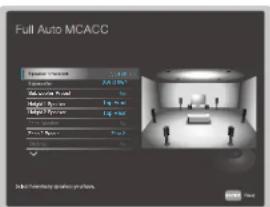
Note that the image on the screen changes each time you select the number of channels in "Speaker Channels".
- Place the supplied speaker setup microphone at the listening position, and connect it to the SETUP MIC jack on the main unit.
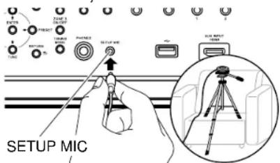
When placing the speaker setup microphone on a tripod, refer to the illustration.
- Confirm a test tone is output from the subwoofer and press ENTER.
- Press ENTER. Then, test tones are output from each speaker, and the connected speakers and the noise in the surrounding environment are automatically measured.
- The measurement results in step 4 are displayed. If there is no problem in the detection result of the speaker, select "Next" and press ENTER to output the test tone again to automatically set the settings such as volume level, crossover frequency, etc., to their optimum. (The test tone is automatically output when 10 seconds has elapsed without any operation.)
- When an error message is displayed or when the connected speakers cannot be detected, perform re-measurement by selecting "Retry" and pressing ENTER.
- When it cannot be resolved by performing the re-measurement, confirm if the speakers are connected correctly. If there is any problem with the speaker connection, perform the connection after disconnecting the power cord.






Setup
- Once the measurement is completed, it is possible to perform the measurement in 8 additional listening positions. To perform the measurement, select "Next" and press ENTER, then follow the instructions. To not perform the measurement, select "Finish (Calculate)" and press ENTER. • After each listening position is detected, select "Finish (Calculate)" and press ENTER to complete the detection process.
- Disconnect the speaker setup microphone.




Fine Channel Level
Adjust the volume level of the speakers while listening to the test tone. After firstly adjusting the Front Left speaker to the desired volume, adjust the volume level so that each channel is the same level, starting from the Front Right speaker. Test tone output alternates between the selected speaker and the benchmark speaker, so adjust the volume so it becomes the same.
☐ Front Left (Default Value: 0.0 dB)
Center (Default Value: 0.0 dB)
Front Right (Default Value: 0.0 dB)
Height 1 Left (Default Value: 0.0 dB)
Height 1 Right (Default Value: 0.0 dB)
Height 2 Left (Default Value: 0.0 dB)
Height 2 Right (Default Value: 0.0 dB)
Surround Right (Default Value: 0.0 dB)
Surr Back Right (Default Value: 0.0 dB)
Surr Back Left (Default Value: 0.0 dB)
Surround Left (Default Value: 0.0 dB)
Subwoofer 1 (Default Value: 0.0 dB)
Subwoofer 2 (Default Value: 0.0 dB)
Select a value between "-12.0 dB" and "+12.0 dB" (-15.0 dB" and "+12.0 dB" for subwoofer) (in 0.5 dB increments). A test tone will be output each time you change the value. Select the desired level.
(Height 1 Left, Height 1 Right, Height 2 Left, Height 2 Right, Surr Back Right, Surr Back Left):
- Depending on the use of the ZONE speakers, it may not be possible to select this setting.
■ Fine Speaker Distance
Make fine adjustments to the distance of the speakers from the listening position while listening to the test pulse. After firstly setting the measured distance of the Front Left speaker from the listening position, adjust the distance of the other speakers, starting with the Front Right speaker. The test pulse is output from the selected speaker and the benchmark speaker, so adjust the distance so the point where the test pulse is heard is in the middle of the two speakers.
☐ Front Left (Default Value: 10.0 ft/3.00 m)
Center (Default Value: 10.0 ft/3.00 m)
Front Right (Default Value: 10.0 ft/3.00 m)
Height 1 Left (Default Value: 10.0 ft/3.00 m)
Height 1 Right (Default Value: 10.0 ft/3.00 m)
Height 2 Left (Default Value: 10.0 ft/3.00 m)
Height 2 Right (Default Value: 10.0 ft/3.00 m)
Surround Right (Default Value: 10.0 ft/3.00 m)
Surr Back Right (Default Value: 10.0 ft/3.00 m)
Surr Back Left (Default Value: 10.0 ft/3.00 m)
Surround Left (Default Value: 10.0 ft/3.00 m)
Subwoofer 1 (Default Value: 10.0 ft/3.00 m)
Subwoofer 2 (Default Value: 10.0 ft/3.00 m)
- Default values vary depending on the regions.
- Distance units can be switched by pressing MODE on the remote controller. When the unit is set as feet, you can set between 0.1' and 30' in increments of 0.1' . When the unit is set as meters, you can set between 0.03m and 9.00m in increments of 0.03m .
(Height 1 Left, Height 1 Right, Height 2 Left, Height 2 Right, Surr Back Right, Surr Back Left):
- Depending on the use of the ZONE speakers, it may not be possible to select this setting.



Standing Wave
This controls the affect of the standing waves that occur when sound waves reverberating off obstacles such as walls interfere with the original sound waves.
☐ Main (Default Value: 0.0 dB)
Center (Default Value: 0.0 dB)
Subwoofer (Default Value: 0.0 dB)
Main:
Control the effect of standing waves for speakers other than the center speaker and the subwoofer.
-
After selecting "Filter" with ▲/▼, select the filter to be adjusted from "1" to "3" with ◀ and press ENTER.
-
After selecting the central frequency with ▶ adjust the bandwidth with ▶/ ▶ then adjust the attenuation with / . The central frequency can be selected between "63Hz" and "250Hz". The bandwidth can be selected between "2.0" and "9.8" (0.2 intervals). Attenuation can be selected between "0.0dB" and "12.0dB" (0.5dB intervals).
Center:
Control the effect of speaker standing waves for the center speaker.
-
After selecting "Filter" with ▲/▼select the filter to be adjusted from "1" to "3" with ◀/▶and press ENTER.
-
After selecting the central frequency with ▶ adjust the bandwidth with ▶/ ▶ then adjust the attenuation with / . The central frequency can be selected between "63Hz" and "250Hz". The bandwidth can be selected between "2.0" and "9.8" (0.2 intervals). Attenuation can be selected between "0.0dB" and "12.0dB" (0.5dB intervals).
Subwoofer:
Control the effect of standing waves for the subwoofer.
-
After selecting "Filter" with ▲/▼, select the filter to be adjusted from "1" to "3" with ◀ and press ENTER.
-
After selecting the central frequency with ▶, adjust the bandwidth with ▶/▶, then adjust the attenuation with / . The central frequency can be selected between "63Hz" and "250Hz". The bandwidth can be selected between "2.0" and "9.8" (0.2 intervals). Attenuation can be selected between "0.0dB" and "12.0dB" (0.5dB intervals).






EQ Adjust
You can adjust the output volume of the range of each connected speaker how you like while listening to test noises. You can adjust the volume of the different sound ranges for each of the speakers. You can select up to 4 bands for the Subwoofer and 9 bands for all other speakers. If the overall volume balance changes by adjusting the volume of each frequency, you can readjust the balance in "Trim".
☐ Front Left (Default Value: 0.0 dB)
Center (Default Value: 0.0 dB)
Front Right (Default Value: 0.0 dB)
Height 1 Left (Default Value: 0.0 dB)
Height 1 Right (Default Value: 0.0 dB)
Height 2 Left (Default Value: 0.0 dB)
Height 2 Right (Default Value: 0.0 dB)
Surround Right (Default Value: 0.0 dB)
Surr Back Right (Default Value: 0.0 dB)
Surr Back Left (Default Value: 0.0 dB)
Surround Left (Default Value: 0.0 dB)
Subwoofer (Default Value: 0.0 dB)
- The result may not be as expected depending on the input source and listening mode setting.
Front Left, Front Right:
After selecting the speaker frequency from between "63 Hz" and "16 kHz" with the cursors ▶/ ▶, adjust the volume of that frequency between "-12.0 dB" and "+12.0 dB" with ▶/ ▶. To readjust the overall volume balance with "Trim", select "Trim" in ▶/ ▶, and use ▶/ ▶ adjust the volume.
- If "OVER!" is displayed during adjustment, the volume of the frequency band or another frequency band is too high, so reduce the volume of the frequency bands until the display disappears.
- "63 Hz" can only be selected when this speaker is set to "Large" in "System Setup" - "Speaker" - "Crossover".
Center, Surround Right, Surround Left:
After selecting the speaker frequency from between "63 Hz" and "16 kHz" with the cursors ▶/▶, adjust the volume of that frequency between "-12.0 dB" and "+12.0 dB" with ▶/▼. To readjust the overall volume balance with "Trim", select "Trim" in ▶/▶, and use ▶/▼ adjust the volume.
- If "OVER!" is displayed during adjustment, the volume of the frequency band or another frequency band is too high, so reduce the volume of the frequency bands until the display disappears.
- "63 Hz" can only be selected when this speaker is set to "Large" in "System Setup" - "Speaker" - "Crossover".
- If an item cannot be selected even though connection is correct, check that the settings in "System Setup" - "Speaker" - "Configuration" - "Speaker Channels" matches the number of connected channels.





Height 1 Left, Height 1 Right, Height 2 Left, Height 2 Right, Surr Back Right, Surr Back Left:
After selecting the speaker frequency from between "63 Hz" and "16 kHz" with the cursors ▶ ▶ adjust the volume of that frequency between "-12.0 dB" and "+12.0 dB" with ▶ ▶ to readjust the overall volume balance with "Trim", select "Trim" in ▶ ▶ and use ▶ ▶ to adjust the volume.
- If "OVER!" is displayed during adjustment, the volume of the frequency band or another frequency band is too high, so reduce the volume of the frequency bands until the display disappears.
- "63 Hz" can only be selected when this speaker is set to "Large" in "System Setup" - "Speaker" - "Crossover".
- Depending on the use of the ZONE speakers, it may not be possible to select this setting.
- If an item cannot be selected even though connection is correct, check that the settings in "System Setup" - "Speaker" - "Configuration" - "Speaker Channels" matches the number of connected channels.
Subwoofer:
After selecting the speaker frequency from between "31 Hz" and "250 Hz" with the cursors ▶/▶ adjust the volume of that frequency between "-12.0 dB" and
"+12.0 dB" with ▲▼To readjust the overall volume balance with "Trim", select "Trim" in ◀▼ and use ▲ to adjust the volume.
- If "OVER!" is displayed during adjustment, the volume of the frequency band or another frequency band is too high, so reduce the volume of the frequency bands until the display disappears.
- This cannot be selected if "No" is set in "System Setup" - "Speaker" - "Configuration" - "Subwoofer".
EQ Professional
You can automatically measure and calibrate the reverberation characteristics (how the sound echoes) of the room. First measure the reverberations with "Reverb Measurement", then check the results with "Reverb View". Specify the calibrated time position in "Advanced EQ Setup" based on the measured results to automatically calibrate the reverberation characteristics.
☐ Reverb Measure (Default Value: without EQ)
Measure the reverberation characteristics of the room. After making the following settings, place the speaker setup microphone in the listening position, and connect to the SETUP MIC jack on the main unit. Press ENTER and follow the on screen instructions.
| without EQ MCACC is used to measure the reverberation characteristics of the room without any adjustments made to the equalizer of the speakers. |
| with EQ Measures the reverberation characteristics of the room using the adjustments to the equalizer of the speakers saved in the MCACC Memory. |
Reverb View
The results of the measurements of the reverberation characteristics are shown in graphs for each speaker and frequency. If there is no reverberation, the graph stays horizontal, but if there is reverberation the graph rises to the right. If the "Symmetry" calibration type has been selected and Full Auto MCACC was performed, predicted values for the reverberation characteristics after calibration are also shown.




Advanced EQ Setup
Reverberation characteristics are automatically calibrated according to the settings made. After making the following settings, place the speaker setup microphone in the listening position, and connect to the SETUP MIC jack on the main unit. Press ENTER and follow the on screen instructions.
Time Position (Default Value: 30 - 50 msec)
Specify the calibrated time position in the range between "0 - 20 msec" and "60 - 80 msec" (10 msec intervals).
If the reverberation characteristics differ for each frequency or each channel in the Reverb View graph, we recommend selecting "30 - 50 msec". If the overall reverberation characteristics are similar, we recommend selecting "60 - 80 msec".
EQ Type (Default Value: Symmetry)
Select the calibration type.
| Symmetry Speakers that make one set as a left and right pair have their frequency characteristics calibrated flatly. Speakers not in pairs, such as the center speaker, are adjusted individually. Select when you want to give weight to phase characteristics for calibration. |
| AllChannelAdjustFlatly calibrates individually the frequency characteristics of all speakers. Select when you want to give weight to frequency characteristics for calibration. |
| Front Align Calibrates speakers other than the front speakers so their characteristics match those of the front speakers (front speakers are not calibrated). Select when you want to give weight to characteristics of the front speakers for calibration. |
Standing Wave Multi Position (Default Value: No)
When you select "2" to "9", standing wave calibration can be performed at multiple listening positions along with the main listening position. If there is only one listening position, select "No".
- If you select "2" to "9", calibration is first performed for the locations other than the main position, then the main position is calibrated last.





MCACC Data Check MCACC Data Check
Setup
You can check the number of speaker channels connected and the content and values you have set for each of the speaker settings.
Speaker Setting
You can check the number of speaker channels connected and the large and small settings you have set for the low range reproduction capabilities for each of the speakers.
Channel Level
You can check the output level settings for each of the speakers.
Speaker Distance
You can check the distance from each speaker to the listening position.
Standing Wave
You can check the settings of the standing wave control filter.
Acoustic Calibration EQ
You can check the calibration values for the frequency characteristics of each speaker that were set in "Manual MCACC".
Group Delay
You can check the group delay of speakers before and after calibration.






Data Management Data Management
Setup
You can change the name of the MCACC Memory, or copy or delete the settings you have made.
■ Memory Rename
Change the name of the MCACC Memory.
☐ M1 (Default Value: Memory 1)
☐ M2 (Default Value: Memory 2)
☐ M3 (Default Value: Memory 3)
You can select a name for the memory from "Memory 1", "Symmetry", "All Adj", "F.Align", "Movie", "Music", "Game", "Party", "Sofa", and "Seat".
MCACC Memory Copy
Copy the speaker settings from a Memory to another Memory. After making the following settings, press ENTER and follow the on screen instructions.
☐ Copy (Default Value: All Data)
| All Data Copy all settings. | |
| Level & Distance | Copy only the output level and distance from the listening position for each speaker. |
☐ Copy from (Default Value: M1.Memory 1)
Select the Memory you want to copy.
☐ Copy to (Default Value: M1.Memory 1)
Select the Memory you want to copy to.
MCACC Memory Clear
Delete the speaker settings from a Memory. After selecting the memory, press ENTER and follow the on screen instructions.


Network/Bluetooth
Menu operations

Make settings related to network connections and BLUETOOTH.
Use the on-screen displays (OSD) that appear on the TV to make the settings. Press ⬆ on the remote controller to display the Home screen, select "Network/Bluetooth" with the cursors on the remote controller, then press ENTER.

Select the item with the cursor ▲ /▼/ ← buttons of the remote controller and press ENTER to confirm your selection. Use the cursors ← → change the default values.
• To return to the previous screen, press ↗
• To exit the settings, press






Network
Setup
- When LAN is configured with a DHCP, set "DHCP" to "Enable" to configure the setting automatically. ("Enable" is set by default) To assign fixed IP addresses to each components, you must set "DHCP" to "Disable" and assign an address to this unit in "IP Address" as well as set information related to your LAN, such as Subnet Mask and Gateway.
Connect the unit to the network via a wireless LAN router. - When switching between "On" and "Off(Wired)", stop the Network service. Also, when group playback is in process, cancel the group playback once, and then switch the setting.
On Wireless LAN connection
Off(Wired) Wired LAN connection
You can configure wireless LAN settings by pressing ENTER when "Start" is displayed.
The information of the connected access point will be displayed.
SSID SSID of the connected access point.
Signal Signal strength of the connected access point.
Status Status of the connected access point.
☐ Wi-Fi (Default Value: Off(Wired))
☐ Wi-Fi Setup (Default Value: -)
☐ WI-Fi Status (Default Value: -)
☐ MAC Address (Default Value: -)
Check the MAC address of this unit.
This value is specific to the component and cannot be changed.
☐ DHCP (Default Value: Enable)
Enable Auto configuration by DHCP
Disable Manual configuration without DHCP
- If you select "Disable", you must set "IP Address", "Subnet Mask", "Gateway", and "DNS Server" manually.
☐ IP Address (Default Value: 0.0.0.0)
Displays/Sets the IP address.
☐ Subnet Mask (Default Value: 0.0.0.0)
Displays/Sets the subnet mask.
☐ Gateway (Default Value: 0.0.0.0)
Displays/Sets the gateway.
☐ DNS Server (Default Value: 0.0.0.0)
Displays/Sets the primary DNS server.





Network
Setup
□ Proxy URL (Default Value: -)
Displays/Sets the proxy server URL.
☐ Proxy Port (Default Value: 8080)
Displays/Sets the proxy server port number when you input "Proxy URL".
☐ Friendly Name (Default Value: Pioneer VSX-LX805 XXXXXX)
Change the device name for this unit which is shown on other devices connected to the network to an easily recognized name.
-
Press ENTER to display the Edit screen.
-
Select a character or symbol with the cursors, and press ENTER. Repeat it to input 31 or less characters.
"A/a": Switches between upper and lower cases. (Pressing MODE on the remote controller also toggles between upper and lower cases)
"←""→": Moves the cursor in the arrow direction.
"Removes a character on the left of the cursor."
"Enter a space.
- Pressing CLEAR on the remote controller will remove all the input characters.
- After inputting, select "OK" with the cursors, and press ENTER. The input name will be saved.
AirPlay (Default Value: On)
Select whether or not to use the AirPlay function.
On When this function is used
O! When this function is not used
AirPlay Device Name (Default Value: PionVQX-LX805 XXXXXX)
Change the model name of this unit which is displayed on the AirPlay-connected device to an easily recognized name.
-
Press ENTER to display the Edit screen.
-
Select a character or symbol with the cursors, and press ENTER. Repeat it to input 31 or less characters.
"A/a": Switches between upper and lower cases. (Pressing MODE on the remote controller also toggles between upper and lower cases)
"←""→": Moves the cursor in the arrow direction.
"Removes a character on the left of the cursor."
"": Enters a space.
- Pressing CLEAR on the remote controller will remove all the input characters.
- After inputting, select "OK" with the cursors, and press ENTER. The input name will be saved.
- This function cannot be used when registering this unit to Home App.




Network
Setup
AirPlay Password (Default Value: -)
You can set a password of up to 31 characters so that only registered users can use AirPlay.
-
Press ENTER to display the Edit screen.
-
Select a character or symbol with the cursors, and press ENTER. Repeat it to input 31 or less characters.
"A/a": Switches between upper and lower cases. (Pressing MODE on the remote controller also toggles between upper and lower cases)
"←" "→": Moves the cursor in the arrow direction.
"Removes a character on the left of the cursor."
"": Enters a space.
- To select whether to mask the password with "*" or display it in plain text, press +Fav on the remote controller.
- Pressing CLEAR on the remote controller will remove all the input characters.
- After inputting, select "OK" with the cursors, and press ENTER. The input password will be saved.
- This function cannot be used when registering this unit to Home App.
☐ Privacy Statement (Default Value: Not Accepted)
When using a network service that requires a login name, email address, password, etc., you need to agree to the Privacy Statement of our company.
- This setting can be made after confirming the Privacy Statement. When you select "Privacy Statement" and press ENTER, the Privacy Statement is displayed.
- When "Not Accepted" is selected, you will log out from the network service you have logged in.
☐ Network Check (Default Value: -)
You can check the network connection. Press ENTER when "Start" is displayed.
- Wait for a while if "Network" cannot be selected. It will appear when the network feature is started.





Bluetooth
Setup
Change the settings for the BLUETOOTH function.
- Wait for a while if "Bluetooth" cannot be selected. It will appear when the BLUETOOTH function is started up.
Bluetooth Receiver
Bluetooth Receiver (Default Value: On)
Select whether or not to use the function that receives audio from BLUETOOTH wireless technology enabled devices.
On When this function is used
Off When this function is not used
☐ Auto Input Change (Default Value: On)
When a BLUETOOTH enabled device is played while it is connected to the unit, the input of the unit can be automatically switched to "BLUETOOTH".
On The input will automatically become "BLUETOOTH" when a BLUETOOTH enabled device is connected.
Off The function is disabled.
- If the input is not switched automatically, set to "Off" and change the input manually.
☐ Auto Reconnect (Default Value: On)
This function automatically reconnects to the BLUETOOTH wireless technology enabled device connected last when you change the input to "BLUETOOTH".
- This may not work with some BLUETOOTH wireless technology enabled devices.
On When this function is used
Off When this function is not used
□ Pairing Information (Default Value: -)
You can initialize the pairing information stored on this unit. If you are no longer able to connect with a device you have paired, try doing this. (→p194)
Pressing ENTER when "Clear" is displayed initializes the pairing information stored on this unit.
- This function does not initialize the pairing information on the BLUETOOTH wireless technology enabled device. When pairing the unit again with the device, be sure to clear the pairing information on the BLUETOOTH wireless technology enabled device in advance. For information on how to clear the pairing information, refer to the BLUETOOTH wireless technology enabled device's instruction manual.
☐ Device (Default Value: -)
Displays the name of the BLUETOOTH wireless technology enabled device connected to the unit.
- The name is not displayed when "Status" is "Ready" and "Pairing".
□ Status (Default Value: -)
Displays the status of the BLUETOOTH wireless technology enabled device connected to the unit.
Ready Not paired
Pairing Paired
Connected Successfully connected




Bluetooth
Setup
Bluetooth Transmitter
☐ Bluetooth Transmitter (Default Value: Off)
Select whether or not to use the function that transmits audio from this unit to BLUETOOTH wireless technology enabled devices.
| On (Tx) When this function is to be used (played back only on BLUETOOTH wireless technology enabled devices) | |
| On (Main + Tx) | When this function is to be used (played back both on this unit and on BLUETOOTH wireless technology enabled devices) |
| Off When this function is not used | |
☐ Search Devices (Default Value: -)
Search for a BLUETOOTH wireless technology enabled device that is able to receive the audio from this unit. Select "Start" then press ENTER. A list of the names of BLUETOOTH wireless technology enabled devices that are able to receive is displayed. Select the device to be connected with the cursors ▲,▼ then pairing begins when you press ENTER.
☐ Output Level (Default Value: Variable)
You can select whether to adjust the volume on this unit or to adjust it on the BLUETOOTH wireless technology enabled device.
| Variable To use the volume controls on this unit | |
| Fixed To use the volume controls on the BLUETOOTH wireless technology enabled device |
☐ aptX HD (Default Value: Off)
It is possible to use aptX HD to connect a BLUETOOTH wireless technology enabled device and this unit.
- The codec of the receiving device must be compatible with aptX HD.
On When this function is used
Off When this function is not used
☐ Low Latency Mode (Default Value: Off)
If the audio from a device connected via BLUETOOTH is delayed compared to the video on the TV when watching a gaming screen, etc., you can reduce the audio delay.
On When this function is used
Off When this function is not used
☐ Pairing Information (Default Value: -)
You can initialize the pairing information stored on this unit. If you are no longer able to connect with a device you have paired, try doing this. (→p194)
Pressing ENTER when "Clear" is displayed initializes the pairing information stored on this unit.
- This function does not initialize the pairing information on the BLUETOOTH enabled device. When pairing the unit again with the device, be sure to clear the pairing information on the BLUETOOTH enabled device in advance. For information on how to clear the pairing information, refer to the BLUETOOTH enabled device's instruction manual.



Bluetooth
Setup
☐ Device (Default Value: -)
Displays the name of the BLUETOOTH wireless technology enabled device connected to the unit.
- The name is not displayed when "Status" is "Ready" and "Pairing".
□ Status (Default Value: -)
Displays the status of the BLUETOOTH wireless technology enabled device connected to the unit.
| Ready Not paired | |
| Pairing Paired | |
| Connected Successfully connected | |
| Connected (aptX) | Successfully connected with aptX compatible device |
| Connected (aptX HD) | Successfully connected with aptX HD compatible device |




Web Setup
Menu operations
You can make the settings for the network function of this unit using an Internet browser on a PC, smartphone, etc.
- Press ⬆ on the remote controller to display the Home screen.
- Select "Network/Bluetooth" - "Network" with the cursors, then take a note of the IP address displayed in "IP Address".
- Start the internet browser on your PC or smartphone and enter the IP address of the unit in the URL field.
- The screen for entering the user name and password is displayed. Enter the following then click "OK".
User name: admin (fixed)
Password: admin (default value)
- You can change the password after logging in.
-
Input is required again if you close the browser.
-
Change the password.
- Take a note of the password so that you do not forget it. If you do forget it, reset the unit (→p187) then log in again with the initial settings (admin).
- Information for the unit (Web Setup screen) is displayed in the internet browser.

- After changing the settings, select "Save" to save the settings.


Device Information
You can change the Friendly Name or AirPlay Device Name, set an AirPlay Password, etc.
Control4: Register this unit if you are using a Control4 system.
Firmware Update: Select the firmware file you have downloaded to your PC so you can update this unit.
Network Setting
Status: You can see information for the network such as the MAC address and IP address of this unit.
Network Connection: You can select a network connection method. If you select "Wireless", select an access point from "Wi-Fi Setup" to connect.
DHCP: You can change DHCP settings. If you select "Off", set "IP Address", "Subnet Mask", "Gateway" and "DNS Server" manually.
Proxy: Display and set the URL for the proxy server.


Initial Setup with Auto Start-up Wizard
Operations


When you turn the unit on for the first time after purchase, the Initial Setup screen is automatically displayed on the TV to allow you to make settings required for startup using simple operations following on-screen guidance.
- Switch the input of the TV to the input connected to the unit.
- Put batteries into the remote controller of this unit.
- Press on the remote controller to turn the unit on
- When the language selection screen is displayed on TV, select the language with the cursors ▲/▼ and press ENTER.
- To make the network connection settings, select "Yes" and press ENTER.
- Select the item with the cursors of the remote controller, and press ENTER to confirm your selection. To return to the previous screen, press ↗.
- If you have terminated the Initial Setup halfway, turn this unit to standby mode. Then turning the power on again can display the Initial Setup again. Unless you do the Initial Setup to the end or select "Never Show Again" in the screen shown after setting the Network Connection, the wizard screen is shown every time the power is turned on.
- To perform the Initial Setup again after the setting is completed, press ,select "System Setup" - "Miscellaneous" - "Initial Setup", and press ENTER.



Network Connection
- A confirmation screen asking you whether to agree to the privacy statement is displayed during network setting. If you agree, select "Accept" and press ENTER.
- Select the type of connection to the network. To use the Chromecast built-in function to connect, select "Yes" and press ENTER. The Google Home app is required to use the Chromecast built-in function. Download the Google Home app from Google Play or the App Store to your smart phone or tablet.
- Google Home app can be used on the following operating systems. (As of January 2023)
Android™: Android 6.0 or later.
iOS: iOS 12.0 or later. Compatible with iPhone ^® , iPad ^® , and iPod touch ^® .

If you select "No", you can connect using either wired LAN or Wi-Fi.
"Wired": Use a wired LAN to connect to a network.
"Wireless": Wi-Fi connection using an access point such as a wireless LAN router.
- There are two methods for Wi-Fi connection.
"Scan Networks": Search for an access point from this unit. Find out the SSID of the access point beforehand.
"Use iOS Device (iOS7 or later)": Share the Wi-Fi settings of your iOS device with this unit. - If you select "Scan Networks", there are another two types of connection methods. Check the following.
"Enter Password": Enter the password (or key) of the access point to connect.
"Push Button": If the access point is equipped with an automatic setting button, you can connect without entering the password.
- If the SSID of the access point is not displayed, select "Other..." with the cursor ▶ on the SSID list screen, press ENTER, and then follow the on-screen instructions.


Setup
Keyboard Input
To switch between upper and lower cases, select "A/a" on the screen, and press ENTER on the remote controller.
Press + Fav on the remote controller to select whether to mask the password with "*" or display it in plain text. Pressing CLEAR on the remote controller will remove all the input characters.
1. Speaker Setup
- Select the connected speaker configuration, and press ENTER. Note that the image on the screen changes each time you select the number of channels in "Speaker Channels".

flowchart
graph TD
    A["Speaker Setup"] --> B["1: Display screen, 2D/40/50"]
    B --> C["2: Display screen, 2D/40/50"]
    C --> D["3: Display screen, 2D/40/50"]
    D --> E["4: Display screen, 2D/40/50"]
    E --> F["5: Display screen, 2D/40/50"]
    F --> G["6: Display screen, 2D/40/50"]
    G --> H["7: Display screen, 2D/40/50"]
    H --> I["8: Display screen, 2D/40/50"]
① Select to suit the number of speaker channels connected.
② Set whether a subwoofer is connected or not.
3 Set the speaker type if height speakers are connected to the HEIGHT 1 terminals.
4 Set the speaker type if height speakers are connected to the HEIGHT 2 terminals.
⑤ Set the connection of speakers to Zone 2, Zone 3 speaker terminals.
6 Set an output destination of the audio output from ZONE 2 PRE/LINE OUT/ZONE B LINE OUT jack.
⑦ Set whether the front speakers are bi-amp connected.
⑧ Set the impedance of the connected speakers.
-
The speaker combination selected in step 1 is displayed. "Yes" is displayed for the selected speakers. If the setting is correct, press ENTER.
-
Select "Next" and press ENTER. Then a test tone is output from each speaker to confirm the connection. Selecting each speaker with the cursors ▲ will


Setup
output the test tone. Press ENTER after confirmation.
- If there is no problem with the speaker connection, select "Next" and press ENTER. To return to "Speaker Setup", select "Back to Speaker Setup" and press ENTER.
2. Multi Zone Sound Check
Output test tones to ZONE 2/ZONE 3 to enjoy audio in a separate room (ZONE 2/ZONE 3) in addition to the main room.
3. ARC Setup
If you have connected a TV that supports ARC, select "Yes" and press ENTER.
4. Room EQ
Measurements are performed to calibrate the sound field to suit the room's environment. You can choose either "Dirac Live (Advanced Users Only)" or "Full Auto MCACC" to perform the measurements. Select "Not Now" if measurement is not to be performed. Note that both measurement methods are also available after you have completed Initial Setup.
■ When measuring with Dirac Live
Download the Pioneer Remote App to your mobile device and use the app to operate the measurements. For details on how to measure with "Dirac Live", refer to "Measuring with Dirac Live" (→p178).
■ When measuring with Full Auto MCACC
Use the automatic sound field calibration technology built into the unit. For details on how to measure with "Full Auto MCACC", refer to "Measuring with Full Auto MCACC" ( p180 ).
- Both measurement methods use the supplied speaker setup microphone.
- Each speaker outputs the test tone at high volume during measurement, so be careful of your surroundings. Also, keep the room as quiet as possible during measurement.
- If you connect a subwoofer, check the power and volume of the subwoofer. Set the subwoofer volume to more than half.
- If the power of this unit suddenly turns off, the wires in the speaker cables have touched the rear panel or other wires, and the protection circuit is working. Twist the wires again securely, and make sure they do not stick out
of the speaker terminals when connecting.
The screen indicating that Initial Setup is complete is displayed when the measurements are finished. Press ENTER while "Finished" is being displayed to exit the Initial Setup.
☐ Measuring with Dirac Live ( p178)
☐ Measuring with Full Auto MCACC (→p180)





■ Measuring with Dirac Live
Use the Pioneer Remote App to use Dirac Live to take measurements. Use the most recent version. Note that you cannot make settings using operations on this unit. Refer to "Pioneer Remote App" (→p181) for information about the app. Also have a tripod ready to set up the speaker setup microphone.
- Calibration takes about 20 minutes to be completed.
Dirac Live ^® is an advanced room correction technology developed by Dirac Research. As one of the most advanced room correction technology available on the market, Dirac Live helps listeners to correct for one of the weakest components in the audio chain: the listening room. Dirac Live not only corrects the frequency response, but also the impulse response of the loudspeakers in a room, yielding improved imaging and timbre, better clarity, tighter bass, and less early reflections, as well as reduced resonances and room modes.
- Select "Start Dirac Live" in the "Dirac Live" screen, then press ENTER.
- Connect the supplied Speaker Setup microphone to the SETUP MIC jack on the main unit.
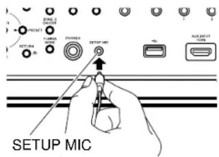
- When you start the Pioneer Remote App, a screen automatically appears to guide you through measurement, so tap "Start".
- If the guidance screen does not automatically appear, after tapping this unit when it appears on the screen, tap "■" at the top left of the screen and select "Dirac Live".
- Tap "Yes", confirm that the displayed speaker configuration is correct, then tap "Yes".
- If the number of speaker channels set in "1.Speaker Setup" in Initial Setup is different to the number of connected speaker channels, an error is displayed and measurement cannot be performed.
- Select whether to use Dirac Live Bass Control ( p182). Select "Use" to




Setup
use it and log into Dirac Live.
- Select the method of measurement. There are two methods of measuring to choose from; "Quick Measurement" which measures 3 locations; at the listening position and to the left and right of the listening position; and "Full Measurement" which measures 9 positions including the listening position. Tap the method you prefer.
"Quick Measurement": Set up the microphone at ear height in the listening position for measurement. Next measure by setting up the microphone between 50 and 100 cm (20" and 40") away to the left and right of the listening position.
"Full Measurement": Set up the microphone at ear height in the listening position for measurement. Next, measure in 8 positions to the front, back, left, right, etc., centered on the listening position. Measure by setting up the microphone in each of these positions, between 50 and 100 cm (20" and 40") away from the listening position.
"Quick Measurement" "Full Measurement"
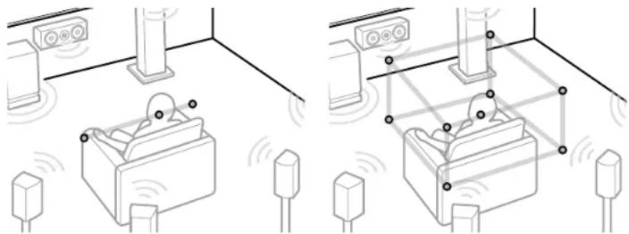
natural_image
Diagram showing two configurations of smart lockers in a room with sensors and lighting (no text or symbols)The illustration shows an image.


Setup
- The guidance about outputting the test tone is displayed. Refer to the illustration to set up the speaker setup microphone in the listening position. Follow the on-screen instructions to measure.
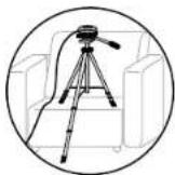
- Measurement may not be possible if the test tone is too loud or too soft. Tap "Level Adjust" to adjust the volume of the test tone.
- When measurement is complete, "Calculating results" is displayed on the screen. Tap "Transfer to your product" to transfer the measurement data to the unit.

Disconnect the speaker setup microphone.
The speaker adjustments based on the measurement results are saved in the unit. You can modify 3 patterns of the filter curves from the measurement results and register them in 3 slots (→p184). The filter curves that you register can be selected with "Room EQ" - "Dirac Live" (→p93) in "AV Adjust".
- When measurement is performed with Dirac Live, selection in "Advanced MCACC" - "Manual MCACC" (→p160) and "MCACC Data Check" (→p165) of the Home screen is no longer available. Furthermore, the measurement results are also reflected in "System Setup" - "Speaker" -
"Distance" (→p139) of the Home screen, and you will no longer be able to change the values. (The setting units are displayed as "msec".)






■ Measuring with Full Auto MCACC
Place the supplied speaker setup microphone in the listening position, measure the test tones emitted by the speakers, then the unit automatically sets the optimum volume level for each speaker, the crossover frequencies, and the distance from the listening position. This also reduces the effect of the standing wave in accordance with the viewing environment and automatically adjusts the equalizers for the speakers and enables correction of distortion caused by the acoustic environment of the room.
- Calibration takes between 3 and 12 minutes to be completed.
- Select "Exit Dirac Live & use MCACC" in the "Dirac Live" screen, then press ENTER.
- Place the supplied speaker setup microphone at the listening position, and connect it to the SETUP MIC jack on the main unit.
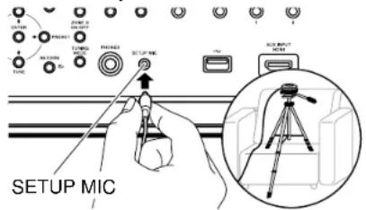
When placing the speaker setup microphone on a tripod, refer to the illustration.
- Confirm a test tone is output from the subwoofer and press ENTER.
- Press ENTER to output test tones from each speaker, and the connected speakers and the noise in the surrounding environment are automatically measured.
- The measurement results in step 3 are displayed. If there is no problem in the detection result of the speaker, select "Next" and press ENTER to output the test tone again to automatically set the settings such as volume level, crossover frequency, etc., to their optimum. (The test tone is automatically output when 10 seconds has elapsed without any operation.)
- When an error message is displayed or when the connected speakers cannot be detected, perform re-measurement by selecting "Retry" and pressing ENTER.
Setup
- When it cannot be resolved by performing the re-measurement, confirm if the speakers are connected correctly. If there is any problem with the speaker connection, perform the connection after disconnecting the power cord.
- Once the measurement is completed, it is possible to perform the measurement in 8 additional listening positions. To perform the measurement, select "Next" and press ENTER, then follow the instructions. To not perform the measurement, select "Finish (Calculate)" and press ENTER. • After each listening position is detected, select "Finish (Calculate)" and press ENTER to complete the detection process.
- Disconnect the speaker setup microphone.




Pioneer Remote App

Pioneer Remote App (available on iOS and Android™ handsets) is a dedicated app available for free which allows you to use your handset as a remote controller. Along with basic operations such as switching input and adjusting the volume, you can also select a radio station or network service (internet radio or play of a music file) without looking at the TV.
- To use Pioneer Remote App, this unit needs to be connected to the same network as the mobile device.
Main features
- Turning the power On/Off, switching input, adjusting the volume, and other such basic remote controller operations.
- When using Multi-zone (→p108), you can not only control with the app in the main room (where this unit is located), but also in the separate room (ZONE 2/ZONE 3).
- Playing internet radio services (Tuneln Radio, etc.) and selecting stations. Control in the palm of your hands without looking at the TV.
- Play the music files saved on the mobile device via Wi-Fi.
- Play Amazon Music (compatible models only) (→p101)
Initial Setup
- Download the Pioneer Remote App from the App Store or Google Play™ Store.
- Connect the mobile device to the same network as the unit.
- Start the Pioneer Remote App. This unit is displayed automatically when the app is started, so tap the unit when displayed to select it.





Dirac Live

DIRAC
Dirac Live ^® is an advanced room correction technology developed by Dirac Research. As one of the most advanced room correction technology available on the market, Dirac Live helps listeners to correct for one of the weakest components in the audio chain: the listening room. Dirac Live not only corrects the frequency response, but also the impulse response of the loudspeakers in a room, yielding improved imaging and timbre, better clarity, tighter bass, and less early reflections, as well as reduced resonances and room modes.
Additional Functions
Dirac Live Bass Control
Dirac Live Bass Control is a technology to manage low-frequency channel routing from the signal to the playback channels (speakers) of your audio device. Additionally, with full control over the device's channel and frequency routing and output, the Dirac Live room correction technology is significantly augmented. In particular systems with multiple subwoofers will see a substantially improved room correction and bass performance.
To use Dirac Live Bass Control, you need to register with Dirac Live and obtain a Dirac Live Bass Control license. For details, refer to the Dirac Live website. https://www.dirac.com/online-store/



Measuring with Dirac Live
Use the Pioneer Remote App to use Dirac Live to take measurements. Use the most recent version. Note that you cannot make settings using operations on this unit. Refer to "Pioneer Remote App" (→p181) for information about the app. Also have a tripod ready to set up the speaker setup microphone.
- Calibration takes about 20 minutes to be completed.
- Start the Pioneer Remote App and tap the unit when displayed.
- Connect the supplied Speaker Setup microphone to the SETUP MIC jack on the main unit.

- Tap "Yes", confirm that the displayed speaker configuration is correct, then tap "Yes".
- If the setting in "System Setup" - "Speaker" - "Configuration" - "Speaker Channels" (→p134) is different to the number of connected speaker channels, an error is displayed and measurement cannot be performed.
- Select whether to use Dirac Live Bass Control. Select "Use" to use it and log into Dirac Live.
- Select the method of measurement. There are two methods of measuring to choose from; "Quick Measurement" which measures 3 locations; at the listening position and to the left and right of the listening position; and "Full Measurement" which measures 9 positions including the listening position. Tap the method you prefer.
"Quick Measurement": Set up the microphone at ear height in the listening position for measurement. Next measure by setting up the microphone


Setup
between 50 and 100 cm (20" and 40") away to the left and right of the listening position.
"Full Measurement": Set up the microphone at ear height in the listening position for measurement. Next, measure in 8 positions to the front, back, left, right, etc., centered on the listening position. Measure by setting up the microphone in each of these positions, between 50 and 100 cm (20" and 40") away from the listening position.
"Quick Measurement" "Full Measurement"

natural_image
Diagram showing two room layouts with lighting fixtures and sound wave indicators (no text or symbols)The illustration shows an image.
- The guidance about outputting the test tone is displayed. Refer to the illustration to set up the speaker setup microphone in the listening position. Follow the on-screen instructions to measure.

- Measurement may not be possible if the test tone is to loud or too soft. Tap "Level Adjust" to adjust the volume of the test tone.
- When measurement is complete, "Calculating results" is displayed on the screen. Tap "Transfer to your product" to transfer the measurement data to the unit.

- Disconnect the speaker setup microphone.
- When measurement is performed with Dirac Live, selection in "MCACC Pro" - "Manual MCACC" (→p160) and "MCACC Data Check" (→p165) of the Home screen is no longer available. Furthermore, the measurement results are also reflected in "System Setup" - "Speaker" - "Distance" (→p139) of the Home screen, and you will no longer be able to change the values. (The setting units are displayed as "msec".)
Using Dirac Live
You can apply the filter curves adjusted based on the measurement results of Dirac Live. From "Room EQ" - "Dirac Live" (→p93) in "AV Adjust", select from "Slot1" to "Slot3". Note that the same data is saved in all of the slots, but you are able to create your own original sound quality in the following "Manual Adjust" section.
- In the Home screen, when the number of speaker channels, etc., is changed in "System Setup" - "Speaker" - "Configuration" (→p134), the measurement results are deleted.
- When using Dirac Live, signals with a sampling frequency of 32 kHz are not supported.





Manual Adjust
You can modify the filter curve to one you like based on the volume level of the speakers automatically measured with Dirac Live. Edit the filter curve in Pioneer Remote App.
- To adjust the sound quality with "Manual Adjust", it is first necessary to measure the speakers of this unit with Dirac Live (→p178, p182).
- This function cannot be used when speaker measurement is done with Full Auto MCACC (→p158, p180).
Modifying the filter curve
- Start the Pioneer Remote App and tap the unit when displayed.
- Tap "■" in the top left of the Pioneer Remote App screen to display a list of menus, then tap "Manual Adjust".
- Select the slot to modify from "Slot1" to "Slot3", then tap "Next".
-
The measurement results from Dirac Live are registered in all of the slots as the default values.
-
After selecting the speaker to adjust first, modify the filter curve.
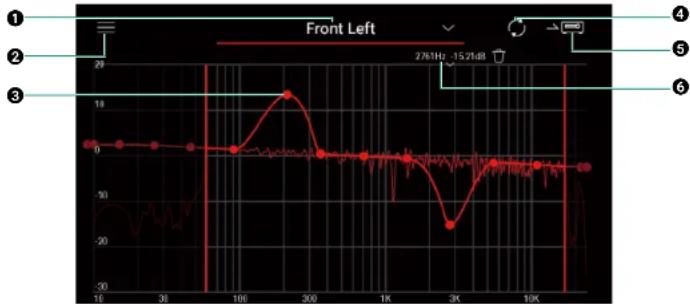
line
| Time (s) | Value | | -------- | ----- | | 16 | 0 | | 30 | 0 | | 100 | 0 | | 300 | 19 | | 1K | -20 | | 3K | -28 | | 10K | -20 |① The speaker currently being adjusted. To adjust another speaker, tap the "next to it and select another speaker.
② Displays the Menu screen. From the menu, you perform actions such as reset the speaker adjustments and cancel and exit the adjustments. You can also copy data from other slots.
③ Drag the points on the filter curve side to side to change the frequency and




Setup
up or down to change the boost.
- You can add a point by tapping on the curve where there isn't a point.
4 Recalculate the characteristics from the adjusted content.
⑤ Transfer the adjusted content to the unit.
⑥ The value of the point being adjusted. Tap the "next to the point to delete it.
- When the Dirac Live Bass Control is enabled, the bar for editing the crossover frequency is displayed. Adjust the crossover value by moving the bar side to side.

- When adjustment is finished, tap 4 to recalculate, then tap 5 to transfer the adjusted data to the unit.
- In the Home screen, when the number of speaker channels, etc., is changed in "System Setup" - "Speaker" - "Configuration", the adjusted content is deleted.
Using an filter curve you have registered
When you select a saved slot in "Room EQ" - "Dirac Live" (→p93) in "AV Adjust", you can use the registered filter curve.


Troubleshooting
Troubleshooting
Before starting the procedure 186
When the unit is operating erratically 187
Try restarting the unit 187
Resetting the unit (this resets the unit settings to the default) 187
Troubleshooting 188
Power 188
■ Audio 189
■ Listening Modes 191
■ Video 192
Linked operation 193
■ Tuner (North American and Taiwanese models) 193
■ BLUETOOTH function 193
■ Network function 195
USB storage device 196
■ Wireless LAN Network 196
■ ZONE B function 197
■ Multi-zone function 197
■ Remote Controller 197
■ Display 197
■ Others 198





Before starting the procedure
Troubleshooting
Problems may be solved by simply turning the power on/off or disconnecting/connecting the power cord, which is easier than working on the connection, setting and operating procedure. Try the simple measures on both the unit and the connected device. If the problem is that the video or audio is not output or the HDMI linked operation does not work, disconnecting/connecting the HDMI cable may solve it. When reconnecting, be careful not to wind the HDMI cable since if wound the HDMI cable may not fit well. After reconnecting, turn off and on the unit and the connected device.
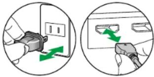
natural_image
Two circular diagrams showing a hand inserting a plug into a socket and then adjusting a green arrow (no text or symbols present)- The AV receiver contains a microPC for signal processing and control functions. In very rare situations, severe interference, noise from an external source, or static electricity may cause it to lockup. In the unlikely event that this happens, unplug the power cord from the wall outlet, wait at least 5 seconds, and then plug it back in.
- Our company is not responsible for damages (such as CD rental fees) due to unsuccessful recordings caused by the unit's malfunction. Before you record important data, make sure that the material will be recorded correctly.






When the unit is operating erratically
Troubleshooting
☐ Try restarting the unit
Restarting this unit may solve the problem. Set the main unit to standby, then after waiting for 5 seconds or more, press and hold the \$TANDBY/ON button of the main unit for at least 5 seconds, and then restart the unit. (The settings on this unit are kept.) If the problem persists after restarting the unit, unplug and plug the power cords or HDMI cable of this unit and connected devices.

☐ Resetting the unit (this resets the unit settings to the default)
If the restart of the unit does not solve the problem, reset the unit, and restore all the settings to the factory default at the time of purchase. This may solve the problem. If the unit is reset, your settings are restored to the default values. Be sure to note down your setting contents before performing the following operations. Note that it is not possible to reset the unit during the Initial Setup process. Before doing the following procedures, press to exit Initial Setup.
- While pressing and holding ZONE CONTROL on the main unit with the unit turned on, press the ⏻STANDBY/ON button.
- "Clear" is displayed on the display, and the unit returns to the standby state. Do not remove the power cord until "Clear" disappears from the display. To reset the remote controller, while pressing and holding MODE, press the CLEAR button at least 3 seconds.






Troubleshooting
Troubleshooting

Power
☐ When the power is turned on, "Diagnostic mode" appears on the display of the main unit
- The protection circuit function may have operated. If the unit suddenly enters the standby state and "Diagnostic mode" appears on the display of the main unit when the power is turned on again, this function is diagnosing whether or not the main unit is malfunctioning or there is an abnormality with the speaker cable connection. When the diagnosis is complete, the following messages are displayed.
| Check speaker | If the unit returns to the normal ON state after "CH SP WIRE" appears on the display, the speaker cable may have been short-circuited. After setting the power of this unit to standby state, connect the speaker cable again. Twist the wires exposed from the tip of the speaker cable so that the wires do not stick out of the speaker terminal. |
| NG: * * * * * | If the operation has stopped with "NG" displayed on the display, set the power of this unit to standby state immediately and remove the power plug from the outlet. The unit may be malfunctioning. Consult a dealer. |

The unit turns off unexpectedly
- The unit automatically switches to standby when the "System Setup" - "Hardware" - "Power Management" - "Auto Standby" setting in the Home screen functions.
- The protection circuit function may have operated due to an abnormal rise in temperature of the unit. In such a case, the power turns off repeatedly even if the power is turned on each time. Secure sufficient ventilation space around the unit, wait for a while until the temperature of the unit decreases. Then, turn the power on again.
WARNING: If smoke, smell or abnormal noise is produced by the unit, unplug the power cord from the outlet immediately, and contact the dealer or our company's support.
(→p148)



Troubleshooting

Audio
- Make sure that the speaker setup microphone is no longer connected.
- Confirm that the connection between the output jack on the connected device and the input jack on this unit is correct.
- Make sure that none of the connecting cables are bent, twisted, or damaged.
- If "MUTING" is displayed on the display and ✗ is blinking, press ✗ on the remote controller to cancel muting.
- While headphones are connected to the PHONES jack, no sound is output from the speakers.
- When "System Setup" - "Source" - "Audio Select" - "Fixed PCM" in the Home Menu is set to "On", no sound is played when signals other than PCM are input. Change the setting to "Off".
Check the following if the problem persists after you have confirmed the above.
☐ No sound from the TV
- Change the input selector on this unit to the position of the terminal to which the TV is connected.
- If the TV doesn't support the ARC function, along with connection by HDMI, connect the TV and this unit using a digital optical cable. (→p64)
- Change the input selector on this unit to the position of the jack to which the player is connected.
- Check the digital audio output setting on the connected device. On some game consoles, such as those supporting DVD, the default setting may be off.
- For some DVD-Video discs, you need to select an audio output format from a menu.
☐ No sound from a connected player
☐ A speaker produces no sound
- Make sure that the polarity (+/-) of the speaker cables is correct, and that no bare wires are in contact with the metal part of speaker terminals.
- Make sure that the speaker cables are not shorting out.
- Check "Connect the Speaker Cables" (→p40) to see if the speaker connections have been made correctly. Settings for the speaker
connection environment need to be made in "Speaker Setup" in Initial Setup. Check "Initial Setup with Auto Start-up Wizard" (→p175). - Depending on the input signal and listening mode, not much sound may be output from speakers. Select another listening mode to see if sound is output.
- If surround back speakers are installed, be sure to install surround speakers as well.
- A maximum of 9 ch playback is possible when Bi-Amping connection is used. Be sure to remove the jumper bar on the speakers when using Bi-Amping connection.



Troubleshooting
☐ The subwoofer produces no sound
If the setting of the front speakers is "Large", the low range elements will be output from the front speakers instead of from the subwoofer during 2 ch audio input of TV or music. To output the sound from the subwoofer, make one of the following settings.
- Change the front speakers settings to "Small".
The low range elements will be output from the subwoofer rather than the front speakers. We do not recommend changing this if your front speakers have good low range reproduction capabilities.
- Change "Double Bass" to "On".
The low range elements of the front speakers will be output from both the front speakers and the subwoofer. Due to this, the bass sound may be emphasized too much. In such a case, do not change the setting, or make the setting with the above option 1.
- For the setting details, refer to "System Setup" - "Speaker" - "Crossover".
- If the input signals do not contain subwoofer audio elements (LFE), the subwoofer may produce no sound.
(→p137)
☐ Noise can be heard
- Using cable ties to bundle analog audio cables, power cords, speaker cables, etc. may degrade the audio performance. Do not bundle the cords.
- An audio cable may be picking up interference. Change the position of the cables.
☐ The beginning of audio received by an HDMI IN cannot be heard
- Since it takes longer to identify the format of an HDMI signal than it does for other digital audio signals, audio output may not start immediately.
☐ Sound suddenly reduces
- When using the unit for extended periods with the temperature inside the unit exceeding a certain temperature, the volume may be reduced automatically to protect the circuits.




Listening Modes
- To enjoy digital surround playback in formats such as Dolby Digital, you need to make a connection for audio signals with an HDMI cable, digital coaxial cable or digital optical cable. Also, audio output need to be set to Bitstream output on the connected Blu-ray Disc player, etc.
- Press i on the remote controller several times to switch the display of the main unit, and you can check the input format.
Check the following if the problem persists after you have confirmed the above.
☐ Cannot select a desired listening mode
- Depending on the connection status of the speaker, some listening modes may not be selected. Check "Speaker Layouts and Selectable Listening Modes" (→p200) or "Input Formats and Selectable Listening Modes" (→p203).
□ Cannot listen to the sound in Dolby TrueHD, Dolby Atmos or DTS-HD Master Audio format
- If the audio in Dolby TrueHD, Dolby Atmos or DTS-HD Master Audio format cannot be output correctly in the source format, set "BD video supplementary sound" (or reencode, secondary sound, video additional audio, etc.) to "Off" in the setting of a connected Blu-ray Disc player, etc. After changing the setting, switch the listening mode to that for each source, and confirm.
□ About Dolby signals
- When surround back speakers are included in the speaker layout, and software that is recorded with the 5.1 channel Dolby audio format is played, the surround channel audio may be output from the surround back speakers.
- Some Dolby Atmos audio format that is used on games, etc., may be recognized as "Multichannel PCM". If this occurs, check the firmware updates for the game console.
□ About DTS signals
- With media that switches suddenly from DTS to PCM, PCM playback may not start immediately. In such a case, stop playback on the player side for approx. 3 seconds or more. Then, resume playback. The playback will be performed normally.
- DTS playback may not be performed normally on some CD and LD players even if the player and this unit are digitally connected. If some processing (e.g., output level adjustment, sampling frequency conversion, or frequency characteristic conversion) has been executed for the DTS signal being output, this unit cannot recognize it as a genuine DTS signal, and noise may occur.
- While playing a DTS-compatible disc, if a pause or skip operation is performed on your player, noise may occur for a short period. This is not a malfunction.






Troubleshooting

Video
- Confirm that the connection between the output jack on the connected device and the input jack on this unit is correct.
- Make sure that none of the connecting cables are bent, twisted, or damaged.
- When the TV image is blurry or unclear, the power cord or connection cables of the unit may have interfered. In such a case, keep distance between TV antenna cable and cables of the unit.
- Check the switching of the input screen on the monitor side such as a TV.
Check the following if the problem persists after you have confirmed the above.
☐ No image appears
- Change the input selector on this unit to the position of the jack to which the player is connected.
☐ No image from a device connected to HDMI IN jack
- To display video from the connected player on the TV while the unit is in standby, you need to enable "System Setup" - "Hardware" - "HDMI" - "HDMI Standby Through" on the Home screen. For details of the HDMI Standby Through function, refer to "System Setup" - "Hardware" - "HDMI".
- To output video to a TV connected to the HDMI OUT SUB jack, press the 📁 button on the remote controller to display "AV Adjust" and select "HDMI" - "HDMI Out", or press the HDMI MAIN/SUB button on the remote controller. Then, select the HDMI OUT jack for output.
- Check if "Resolution Error" is displayed on the main unit display when video input via HDMI IN jack is not displayed. In this case, the TV does not support the resolution of the video input from the player. Change the setting on the player.
- Normal operation with an HDMI-DVI adapter is not guaranteed. In addition, video signals output from a PC are not guaranteed.
- Try switching off the Deep Color function. To turn off the Deep Color function, simultaneously press the PERSONAL PRESET 2 and STANDBY/ON buttons on the main unit. While holding down PERSONAL PRESET 2, press STANDBY/ON repeatedly until "Deep Color:Off" appears on the display. To reactivate the Deep Color function, repeat the above described step until "Deep Color:On" is appeared on the display.
Images flicker
- The output resolution of the player may not be compatible with the resolution of the TV. If the player is connected to this unit with an HDMI cable, change the output resolution on the player. Also this may be solved by changing the screen mode on the TV.
☐ Video and audio are out of synch
- Depending on the settings on your TV and connection environment, the video may be behind the audio. To adjust, press ⚫ on the remote controller, and adjust in "HDMI" - "Sound Delay" in the "AV Adjust". (→p91)







Linked operation
☐ HDMI linked operation does not work with CEC-compliant devices, such as a TV
- In the Home screen of the unit, set "System Setup" - "Hardware" - "HDMI" - "HDMI CEC" to "On".
- It is also necessary to set HDMI linking on the CEC-compliant device. Check the instruction manual.
- When connecting a Sharp brand player or recorder to the HDMI IN jacks, set "System Setup" - "Hardware" - "HDMI" - "HDMI Standby Through" to "Auto".
■ Tuner (North American and Taiwanese models)
☐ Poor reception or much noise
- Recheck the antenna connection.
- Move the antenna away from the speaker cord or power cord.
- Move the unit away from your TV or PC.
- Passing cars or airplanes in the vicinity can cause interference.
- If radio waves are blocked by concrete walls, etc., radio reception may be poor.
- Change the reception mode to mono (→p89).
- When listening to an AM station, operating the remote controller may cause noise.
- FM reception may be clearer if you use the antenna jack on the wall used for the TV.
■ BLUETOOTH function
- Unplug and plug the power cord of the unit, or turn off and on the BLUETOOTH enabled device. Restart of the BLUETOOTH enabled device may be effective.
- BLUETOOTH enabled devices must support the A2DP profile.
- Because a radio wave interference will occur, this unit may not be used near devices such as a microwave oven or cordless phone which use the radio wave in the 2.4 GHz range.
- A metallic object near the unit can affect on the radio wave, and BLUETOOTH connection may not be possible. Check the following if the problem persists after you have confirmed the above.
☐ Cannot transmit from a BLUETOOTH wireless technology enabled device (PC, smartphone, etc.) to this unit
- Check if the BLUETOOTH function of the BLUETOOTH enabled device is enabled. (→p171)





Troubleshooting
☐ Cannot connect a BLUETOOTH wireless technology enabled device (PC, smartphone, etc.) to this unit
- Initialize the pairing information and perform pairing again. (→p171)
Firstly delete all the pairing information saved on this unit. In the Home screen, select "Network/Bluetooth" - "Bluetooth" - "Bluetooth Receiver" - "Pairing Information", then press ENTER while "Clear" is displayed.
Next, delete the pairing information of this unit that is saved on the BLUETOOTH wireless technology enabled device. For information on how to clear the pairing information, refer to the BLUETOOTH enabled device's instruction manual.
Finally, perform pairing again. Refer to "Playing audio from BLUETOOTH wireless technology enabled devices with this unit" (→p84) for pairing instructions.
☐ Cannot transmit from this unit to a BLUETOOTH wireless technology enabled device (wireless headphones, etc.)
- Check that the "Bluetooth Transmitter" setting on this unit is set to either "On(Tx)" or "On(Main + Tx)". (→p172)
☐ Cannot connect this unit to a BLUETOOTH wireless technology enabled device (wireless headphones, etc.)
- Check if the BLUETOOTH function of the BLUETOOTH enabled device is enabled. (→p172)
- Initialize the pairing information and perform pairing again.
Firstly delete all the pairing information saved on this unit. In the Home screen, select "Network/Bluetooth" - "Bluetooth" - "Bluetooth Transmitter" - "Pairing Information", then press ENTER while "Clear" is displayed.
Next, delete the pairing information of this unit that is saved on the BLUETOOTH wireless technology enabled device. For information on how to clear the pairing information, refer to the BLUETOOTH enabled device's instruction manual.
Finally, perform pairing again. Refer to "Transmitting audio from this unit to BLUETOOTH wireless technology enabled devices" (→p86) for pairing instructions.
□ Music playback is unavailable on the unit even after successful BLUETOOTH connection
- If the volume setting on this unit or the BLUETOOTH wireless technology enabled device is low, audio may not be played. Check the volume setting on this unit or the BLUETOOTH wireless technology enabled device.
- Some BLUETOOTH wireless technology enabled devices may be equipped with a Send/Receive selector switch. Try switching the setting to suit the application the device is being used for.
- Depending on the characteristics or specifications of the BLUETOOTH enabled device, music may not be played back on this unit.
□ Sound is interrupted
- There maybe a problem with the BLUETOOTH enabled device. Check the information on a web page.





Troubleshooting
☐ The audio quality is poor after connection with a BLUETOOTH enabled device
- The BLUETOOTH reception is poor. Move the BLUETOOTH enabled device closer to the unit, or remove any obstacle between the BLUETOOTH enabled device and this unit.
Network function
- If you cannot select a network service, start up the network function to select it. It may take approx. one minute to start it up.
- When the NET indicator is blinking, this unit is not properly connected to the home network.
- Unplug and plug the power cords of this unit and the router, or restart the router.
- If the desired router is not displayed in the access point list, it may be set to hide SSID, or the ANY connection may be off. Change the setting and try again.
Check the following if the problem persists after you have confirmed the above.
□ Cannot access the Internet radio
• In the case the service provider has terminated the service, the network service or contents may not be used on this unit.
- Check if your modem and router are properly connected, and they are both turned on.
- Check if the LAN side port on the router is properly connected to this unit.
- Check if connecting to Internet from other devices is possible. If it is not possible, turn off all devices connected to the network, wait for a while, and then turn on the devices again.
- Depending on ISP, setting the proxy server is required.
- Check if the router and modem you are using are supported by your ISP.
□ Cannot access the network server
- This unit needs to be connected to the same router as the network server.
- This unit supports the Windows Media® Player 12 network servers, or NASes that support the home network function.
- Windows Media® Player may require some settings. Refer to "Music Server".
- When using a PC, only the music files registered in the library of Windows Media ^ Player can be played.
(→p118)
☐ Sound is interrupted when playing music files on the network server
- Check if the network server meets the requirements for operation.
- When the PC is serving as the network server, quit application software other than the server software (Windows Media ^ Player 12, etc.).
- If the PC is downloading or copying large files, the playback sound may be interrupted.





Troubleshooting
USB storage device
☐ USB storage device is not displayed
- Check if the USB storage device or USB cable is securely inserted to the USB port of the unit.
- Disconnect the USB storage device once from the unit, and then reconnect it.
• Performance of the hard disk that receive power from the USB port of the unit is not guaranteed. - Depending on the type of content, the playback may not be performed normally. Check the types of supported file formats.
- Operations of USB storage devices equipped with security functions are not guaranteed.
(→p116)
Wireless LAN Network
- Unplug and plug the power cords of this unit and the wireless LAN router, check the power-on status of the wireless LAN router, or restart the wireless LAN router.
Check the following if the problem persists after you have confirmed the above.
□ Cannot access wireless LAN network
- The wireless LAN router setting may be switched to Manual. Restore the setting to Auto.
- Try the manual set-up. The connection may succeed.
- When the wireless LAN router is in stealth mode (mode to hide SSID) or when the ANY connection is off, the SSID is not displayed. Change the setting and try again.
- Check if the SSID and encryption settings (WEP, etc.) are correct. Match the network settings with the settings of this unit.
- Connection to an SSID that includes multi-byte characters is not supported. Set the SSID of the wireless LAN router using single-byte alphanumeric characters only, and try again.
☐ Connected to an SSID different from the selected SSID
- Some wireless LAN routers allow you to set multiple SSIDs for one unit. If connecting to such a router using the automatic setting button, you may end up connecting to an SSID different from the SSID you want to connect to. If this occurs, use the connection method requiring you to enter a password.
□ Playback sound is interrupted, or communication is not possible
- You may not receive radio waves due to poor radio wave conditions. Shorten the distance from the wireless LAN router, or remove obstacles to improve visibility, and connect again. Install the unit away from microwave ovens or other access points. It is recommended to install the wireless LAN router and the unit in the same room.
- If there is a metallic object near the unit, wireless LAN connection may not be possible because the metal affects the radio wave.
- When other wireless LAN devices are used near the unit, other symptoms may occur, such as interrupted playback and impossible communication. You can avoid those problems by changing the channel of your wireless LAN router. For instructions on changing channels, refer to the instruction manual supplied with your wireless LAN router.
- There may not be enough bandwidth available in wireless LAN. Use a wired LAN for connection.



Troubleshooting
ZONE B function
☐ Cannot output audio to ZONE B
- To output audio to ZONE B, set the audio output destination for "Audio" - "Zone B" on "AV Adjust" to "On (A+B)" or "On (B)" and also set "Speaker" - "Configuration" - "Zone 2 Preout" on the System Setup menu to "Zone B".
Multi-zone function
☐ Cannot ZONE-output the audio of externally connected AV components
- If the AV component is not equipped with an HDMI jack, use a digital coaxial cable, digital optical cable or analog audio cable. Also, the audio from externally connected AV components can be output to ZONE 2 only when the audio is analog or 2 ch PCM signal. When the AV component is connected to this unit with an HDMI cable, digital coaxial cable or digital optical cable, change the audio output of the AV component to the PCM output.
- When video and audio via HDMI input are output to ZONE 2, set "Input/Output Assign" - "TV Out / OSD" - "Zone 2 HDMI" (→p129) to "Use" on the System Setup menu.
- To output audio from an externally connected AV component to ZONE 3, use an analog audio cable for connection. Also, audio from externally connected AV components can be output to ZONE 3 only when it is an analog audio signal.
Others
- If the audio signal is from the NET or USB input selector, zone output is not possible for DSD audio signals.
Remote Controller
- Make sure that the batteries are inserted with the correct polarity.
- Insert new batteries. Do not mix different types of batteries, or old and new batteries.
- Make sure that the sensor of the main unit is not subjected to direct sunlight or inverter-type fluorescent lights. Relocate it if necessary.
- If the main unit is installed in a rack or cabinet with colored-glass doors, or if the doors are closed, the remote controller may not work normally.
Display
☐ The display does not light up
- When the Dimmer function is working, the display may go dim or turn off. Press the DIMMER button, and change the brightness level of the display. (→p18)







Others
☐ Strange noise can be heard from the unit
- If you have connected another device to the same outlet as this unit, strange noise may occur under the influence of the device. If the symptom is remedied by removing the power plug of the other device from the outlet, use different outlets for this unit and the device.
☐ The message "Noise Error" appears during Full Auto MCACC
- This can be caused by a malfunction in your speaker unit. Check the speaker output, etc.
☐ The measurement results of Full Auto MCACC show different distances to the speakers from the actual ones
- Depending on the speakers you are using, some errors may occur in the measurement results. If this is the case, make the settings in "System Setup" - "Speaker" - "Distance".
☐ The measurement results of Full Auto MCACC show that the volume level of the subwoofer has been corrected to the lower limit
- The volume level correction of the subwoofer may not have been completed. Lower the volume of the subwoofer before Full Auto MCACC measurement.
☐ The settings in "Crossover", "Distance", and "Channel Level" are returned to the default values
- When measurements are made with Dirac Live, if you change the settings in "Speaker Channels", "Subwoofer", "Height 1 Speaker", or "Height 2 Speaker" in "Speaker" - "Configuration" (→p134) in the System Setup menu, then the measurement results are returned to the default values. Measure again.


Appendix
Appendix
Speaker Layouts and Selectable Listening Modes 200
Input Formats and Selectable Listening Modes 203
Listening Mode Effects 207
Speaker combinations 212
General Specifications 214






Speaker Layouts and Selectable Listening Modes
See the following table for selectable listening modes for each speaker layout.
| Listening mode | Speaker layout (ch) | |||||||||||||||
| 2.1 | 3.1 | 4.1 | 5.1 | 6.1 | 7.1 | 2.1.2 | 3.1.2 | 4.1.2 | 5.1.2 | 6.1.2 | 7.1.2 | 4.1.4 | 5.1.4 | 6.1.4 | 7.1.4 | |
| DD(Dolby Audio - DD) | (*1) | (*1) | (*2) | (*3) | √ | √ | √ | (*2) | (*2) | (*3) | (*2) | (*2) | ||||
| DD+ (Dolby Audio - DD+) | (*1) | (*1) | √ | (*1) | (*1) | (*1) | (*1) | √ | (*1) | (*1) | (*1) | (*1) | (*1) | |||
| DTHD (Dolby Audio - TrueHD) | (*1) | (*1) | √ | (*1) | (*1) | (*1) | (*1) | √ | (*1) | (*1) | (-1) | (*1) | (*1) | |||
| Atmos | √ | √ | √ | √ | √ | √ | √ | √ | √ | √ | √ | √ | ||||
| Atmos 2.0/2.1 | √ | |||||||||||||||
| Atmos 3.0/3.1 | √ | |||||||||||||||
| Atmos 4.0/4.1 | √ | |||||||||||||||
| Atmos 5.0/5.1 | √ | |||||||||||||||
| Atmos 6.0/6.1 | √ | |||||||||||||||
| Atmos 7.0/7.1 | √ | |||||||||||||||
| Atmos 2.0.2/2.1.2 | √ | |||||||||||||||
| Atmos 3.0.2/3.1.2 | √ | |||||||||||||||
| DSur (Dolby Audio - Surr) | √ | √ | √ | √ | √ | √ | √ | √ | √ | √ | √ | √ | √ | √ | √ | √ |
| DSur 2.0/2.1 (Dolby Audio - Surr) | √ | |||||||||||||||
| DSur 3.0/3.1 (Dolby Audio - Surr) | √ | |||||||||||||||
| DSur 4.0/4.1 (Dolby Audio - Surr) | √ | |||||||||||||||
| DSur 5.0/5.1 (Dolby Audio - Surr) | √ | |||||||||||||||
| DSur 6.0/6.1 (Dolby Audio - Surr) | √ | |||||||||||||||
| DSur 7.0/7.1 (Dolby Audio - Surr) | √ | |||||||||||||||
| DSur 2.0.2/2.1.2 (Dolby Audio - Surr) | √ | |||||||||||||||
| DSur 3.0.2/3.1.2 (Dolby Audio - Surr) | √ | |||||||||||||||





Appendix
| Listening mode | Speaker layout (ch) | |||||||||||||||
| 2.1 | 3.1 | 4.1 | 5.1 | 6.1 | 7.1 | 2.1.2 | 3.1.2 | 4.1.2 | 5.1.2 | 6.1.2 | 7.1.2 | 4.1.4 | 5.1.4 | 6.1.4 | 7.1.4 | |
| DTS | √ | √ | √ | √ | √ | √(*3) | (*3) (*3) | (*0) (*3) | (*2) (*3) | (*3) (*3) | √ | √ | √ | √ | ||
| DTS HD | √ | √ | √ | √ | √ | √ | √ | √ | √ | √ | √ | √ | √ | √ | ||
| DTS:X | √ | √ | √ | √ | √ | √ | √ | √ | √ | √ | √ | √ | √ | √ | √ | |
| DTS Neural:X | √ | √ | √ | √ | √ | √ | √ | √ | √ | √ | √ | √ | √ | √ | √ | √ |
| IMAX DTS | √ | √ | √ | √ | √ | √(*4) | (*3) (*3) | (*0) (*3) | (*3) | √ | √ | √(*3) (*4) | √ (*3) | (*2) (*3) | √ | √(*3) (*4) |
| IMAX DTS:X | √ | √ | √ | √ | √ | √ | √ | √ | √ | √ | √ | √ | √ | √ | √ | √ |
| IMAX Neural:X | √ | √ | √ | √ | √ | √ | √ | √ | √ | √ | √ | √ | √ | √ | √ | √ |






Appendix
*1: Reproduced with the sound field according to the number of channels of input signals.
*2: If 4.1 ch or 5.1 ch Dolby signals (DD, DD+, DTHD) are input, surround channel audio is output from the surround back speakers.
*3: Not output from height speakers.
*4: Surround channel audio is output from the surround back speakers.
*5: Not output from surround back speakers.
*6: Output only from front speakers.
*7: Output only from front speakers and center speaker.





Appendix
Input Formats and Selectable Listening Modes
You can select a variety of listening modes according to the audio format of the signal to be input.
- The Stereo mode can be selected with any audio format.
- When analog signals are being input in the Pure Direct mode, the modes switches to the Analog Direct mode which passes signals directly to the amplifier without passing through the DSP (Digital Signal Processor).
- Listening modes available when headphones are connected are Pure Direct and Stereo only.
| Input format\Listening mode | Pure Direct Direct Stereo | DD(Dolby Audio - DD) (*2) | DD+ (Dolby Audio - DD+) (*2)(*3) | DTHD (Dolby Audio - TrueHD) (*2) | Atmos (*11) | DSur (Dolby Audio - Surr) (*11) |
| 2-channel signal input | ||||||
| Analog / PCM | √ | √ | ||||
| Music files / DSD (*1) | √ | √ | ||||
| DD / DD+ / DTHD | √ | √ | ||||
| DTS / DTS 96/24 / DTS Express / DTS-HD HR / DTS-HD MSTR | √ | (*9) | ||||
| Multi-channel signal input | ||||||
| Multich PCM | √ | √ | ||||
| DSD (*1) | √ | √ | ||||
| DD | √ | √ | √ | |||
| DD+ | √ | √ | √ | |||
| DTHD | √ | √ | √ | |||
| ATMOS | √ | √ | ||||
| DTS | √ | √ | ||||
| DTS 96/24 (*13) | √ | √ | ||||
| DTS Express (*14) | √ | |||||
| DTS-HD HR (*14) | √ | √ | ||||
| DTS-HD MSTR (*14) | √ | √ | ||||
| DTS-ES Discrete (*13) | √ | √ | ||||
| DTS-ES Matrix (*13) | √ | √ | ||||
| DTS:X | √ | |||||
| IMAX DTS | √ | |||||
| IMAX DTS:X | √ | |||||






Appendix
| Input format\Listening mode | DTS (*2) DTS | HD DTS:X | DTS Neural:X (*4) | IMAX DTS (*8) | IMAX DTS:X (*8) | IMAX Neural:X (*8) | |
| 2-channel signal input | |||||||
| Analog / PCM | √ | ||||||
| Music files / DSD (*1) | √ | ||||||
| DD / DD+ / DTHD | √ | ||||||
| DTS / DTS 96/24 / DTS Express / DTS-HD HR / DTS-HD MSTR | √ | ||||||
| Multi-channel signal input | |||||||
| Multich PCM | √ | ||||||
| DSD (*1) | √ | ||||||
| DD | √ | ||||||
| DD+ | √ | ||||||
| DTHD | √ | ||||||
| ATMOS | |||||||
| DTS | √ | √ | |||||
| DTS 96/24 (*13) | √ | √ | |||||
| DTS Express (*14) | √ | √ | |||||
| DTS-HD HR (*14) | √ | √ | |||||
| DTS-HD MSTR (*14) | √ | √ | |||||
| DTS-ES Discrete (*13) | √ | √ | |||||
| DTS-ES Matrix (*13) | √ | √ | |||||
| DTS:X | √ | ||||||
| IMAX DTS | √(*12) (*12) | √ | √ | √ | |||
| IMAX DTS:X | √(*12) | √ | |||||





Appendix
| Input format\Listening mode | PCM(Multich PCM) (*2) | DSD(*2)(*10) | Mono | Classical / Unplugged / Ent.Show (Entertainment Show) / Drama / AdvancedGame / Action / Rock/Pop / Sports (*5) | Ext.Stereo / Mono Music (*6) | F.S.Surround(Front Stage Surround)(*7) |
| 2-channel signal input | ||||||
| Analog / PCM | √ | √ | √ | √ | ||
| Music files / DSD (*1) | √ | √ | √ | |||
| DD / DD+ / DTHD | √ | √ | √ | |||
| DTS / DTS 96/24 / DTS Express / DTS-HD HR / DTS-HD MSTR | √ | √ | √ | |||
| Multi-channel signal input | ||||||
| Multich PCM | √ | √ | √ | √ | ||
| DSD (*1) | √ | √ | √ | √ | ||
| DD | √ | √ | √ | |||
| DD+ | √ | √ | √ | |||
| DTHD | √ | √ | √ | |||
| ATMOS | √ | √ | √ | |||
| DTS | √ | √ | √ | |||
| DTS 96/24 (*13) | √ | √ | √ | |||
| DTS Express (*14) | √ | √ | √ | |||
| DTS-HD HR (*14) | √ | √ | √ | |||
| DTS-HD MSTR (*14) | √ | √ | √ | |||
| DTS-ES Discrete (*13) | √ | √ | √ | |||
| DTS-ES Matrix (*13) | √ | √ | √ | |||
| DTS:X | √ | √ | √ | |||
| IMAX DTS | √ | √ | √ | |||
| IMAX DTS:X | √ | √ | √ | |||





Appendix
(*1) You cannot select any mode other than Pure Direct, Stereo, Ext. Stereo and Mono Music if the sampling rate is 5.6/11.2 MHz.
(*2) A center speaker or surround speakers need to be installed.
(*3) If the input source is Blu-ray Disc and the speaker layout is 5.1 ch or less, DD+ cannot be selected. Instead, the listening mode for DD can be selected.
(*4) If the input format is any of the following and the number of channels is monaural, this listening mode becomes unavailable.
- DTS, DTS 96/24, DTS Express, DTS-HD HR, DTS-HD MSTR, PCM, music file
(*5) Surround speakers or height speakers need to be installed.
(*6) A center speaker, surround speakers, or height speakers need to be installed.
(*7) Cannot be selected if "Speaker Virtualizer" (→p140) is set to "Off".
(*8) Cannot be selected when the "IMAX Mode" (→p142) is set to "Off" (the default value is Auto).
(*9) This cannot be selected when the input format is DTS Express.
(*10) Cannot be selected when the input format is monaural.
(*11) The listening mode displayed depends on the speaker layout (→p200). Furthermore, when the setting for "Speaker Virtualizer" (→p140) is "Off" (the default value is On), then modes other than Atmos and Sdr cannot be selected.
(*12) Can only be selected when the "IMAX Mode" (→p142) is set to "Off" (the default value is Auto).
(*13) Displayed as "DTS" on this unit.
(*14) Displayed as "DTS-HD" on this unit.




☐ Speaker Layouts and Selectable Listening Modes (→p200)



Listening Mode Effects
Appendix
In alphabetical order
Action
Mode suitable for movies with a lot of action scenes.
- The speaker calibrations measured with Dirac Live are disabled.
AdvancedGame
Mode suitable for game content.
- The speaker calibrations measured with Dirac Live are disabled.
Classical
Suitable for classical or operatic music. This mode emphasizes the surround channels in order to widen the sound image, and simulates the natural reverberation of a large hall.
- The speaker calibrations measured with Dirac Live are disabled.
Direct/Pure Direct
The "Direct" mode shuts down some processing that can affect sound quality, such as the tone control features, so you can enjoy even better sound quality. The "Pure Direct" mode shuts down even more processes that affects sound quality, so you get a more faithful reproduction of the original sound. In this case, the speaker calibration made with MCACC/Dirac Live is invalid.
Atmos
Since this mode calculates the positional data of audio recorded in Dolby Atmos audio in real-time and outputs it from appropriate speakers, you can enjoy the natural and stereophonic sound field of Dolby Atmos with any speaker layout including connection of only front speakers. Also, the Dolby Atmos sound design can be reproduced more faithfully by connecting surround back speakers or height speakers. You can select this mode when inputting the Dolby Atmos audio format.
Unlike existing surround systems, Dolby Atmos does not rely on channels, but rather enables the accurate placement of sound objects that have independent motion in a 3D space with even greater clarity. Dolby Atmos is an optional audio format for Blu-ray Discs and achieves a more stereophonic sound field by introducing a sound field above the listener.
According to the speaker layout, the following listening modes are displayed.
- Atmos 2.0/2.1: When only front speakers are installed
- Atmos 3.0/3.1: When front speakers and center speaker are installed
- Atmos 4.0/4.1: When front speakers and surround speakers are installed
- Atmos 5.0/5.1: When front speakers, center speaker and surround speakers are installed
- Atmos 6.0/6.1: When front speakers, surround speakers and surround back speakers are installed
Atmos 7.0/7.1: When front speakers, center speaker, surround speakers and surround back speakers are installed
- Atmos 2.0.2/2.1.2: When front speakers and height speakers are installed
- Atmos 3.0.2/3.1.2: When front speakers, center speaker and height speakers are installed
- Atmos: Selectable in the "4.1.2 ch", "5.1.2 ch", "6.1.2 ch", "7.1.2 ch", "4.1.4 ch", "5.1.4 ch", "6.1.4 ch" or "7.1.4 ch" setting with surround speakers and height speakers installed.
- To enable transfer of this audio format, connect via an HDMI cable and set the audio output on the player to Bitstream output.
- When "Speaker Virtualizer" (→p140) is set to "Off" (Default: On), modes other than ☒ Atmos cannot be selected.




Appendix
DD (Dolby Audio - DD)
This mode faithfully reproduces the sound design recorded in the Dolby Digital audio format.
Dolby Digital is a multi-channel digital format developed by Dolby Laboratories, Inc. and is widely adopted for use in movie production. It is also a standard audio format for DVD-Video and Blu-ray Discs. It is possible to record a maximum of 5.1 channels on a DVD-Video or Blu-ray Disc; two front channels, one center channel, two surround channels, and the LFE channel dedicated to the bass region (sound elements for the subwoofer).
- To enable transfer of this audio format, connect via a digital cable and set the audio output on the player to Bitstream output.
This mode faithfully reproduces the sound design recorded in the Dolby Digital Plus audio format.
The Dolby Digital Plus format has been improved based on Dolby Digital, increasing the number of channels and endeavoring to improve sound quality by giving more flexibility in data bit rates. Dolby Digital Plus is an optional audio format based on 5.1 ch for Blu-ray Discs. It is possible to record a maximum of 7.1 channels with additional channels such as the surround back channel.
- To enable transfer of this audio format, connect via an HDMI cable and set the audio output on the player to Bitstream output.
This listening mode expands 2 ch or 5.1 ch input signals to 5.1 ch, 7.1 ch or 5.1.2 ch. This mode expands actual channels to more channels for playback according to the configuration of the connected speakers. Also, even if there is no speaker for expansion, for example when only front speakers are connected, audio of surround channel or height channel is virtually created for expansion playback.
According to the speaker layout, the following listening modes are displayed.
- DSur 2.0/2.1: When only front speakers are installed
- DSur 3.0/3.1: When front speakers and center speaker are installed
- DSur 4.0/4.1: When front speakers and surround speakers are installed
- DSur 5.0/5.1: When front speakers, center speaker and surround speakers are installed
- DSur 6.0/6.1: When front speakers, surround speakers and surround back speakers are installed
- DOSur 7.0/7.1: When front speakers, center speaker, surround speakers and surround back speakers are installed
- DSur 2.0.2/2.1.2: When front speakers and height speakers are installed
- DSur 3.0.2/3.1.2: When front speakers, center speaker and height speakers are installed
- DSur: Selectable in the "4.1.2 ch", "5.1.2 ch", "6.1.2 ch", "7.1.2 ch", "4.1.4 ch", "5.1.4 ch", "6.1.4 ch" or "7.1.4 ch" setting with surround speakers and height speakers installed.
- When "Speaker Virtualizer" (→p140) is set to "Off" (Default: On), modes other than DX DSur cannot be selected.



Appendix
DTHD (Dolby Audio - TrueHD)
This mode faithfully reproduces the sound design recorded in the Dolby TrueHD audio format.
The Dolby TrueHD audio format is a "lossless" format expanded based on the lossless compression technology referred to as MLP, and it faithfully reproduces the master audio recorded in the studio. Dolby TrueHD is an optional audio format based on 5.1 ch for Blu-ray Discs. It is possible to record a maximum of 7.1 channels with additional channels such as the surround back channel. 7.1 ch is recorded at 96 kHz/24 bit, and 5.1 ch is recorded at 192 kHz/24 bit.
- To enable transfer of this audio format, connect via an HDMI cable and set the audio output on the player to Bitstream output.
Drama
Suitable for TV shows produced in a TV studio. This mode enhances the surround effects to the entire sound to give clarity to voices and create a realistic acoustic image.
- The speaker calibrations measured with Dirac Live are disabled.
DSD
This mode is suitable for playing sources recorded in DSD.
- This unit supports the DSD signal input from the HDMI input terminal. However, depending on the connected player, better sound may be obtained by setting the output on the player side to the PCM output.
- This listening mode cannot be selected if the output setting on your Blu-ray Disc/DVD player is not set to DSD.
DTS
This mode faithfully reproduces the sound design recorded in the DTS audio format.
The DTS audio format is a multi-channel digital format developed by DTS, Inc. This format is an optional audio format for DVD-Video and a standard format for Blu-ray Discs.
To enable transfer of this audio format, connect via a digital cable and set the audio output on the player to Bitstream output.
DTS-HD
This mode faithfully reproduces the sound design recorded in the DTS-HD High Resolution Audio audio format or DTS-HD Master Audio.
These audio formats are optional audio format based on 5.1 ch for Blu-ray Discs. It is possible to record a maximum of 7.1 channels with additional channels such as the surround back channel at a sampling rate of 96 kHz and at a resolution of 24 bits.
- To enable transfer of this audio format, connect via an HDMI cable and set the audio output on the player to Bitstream output.
DTS Neural:X
This listening mode expands actual channels to more channels for playback to suit the configuration of the connected speakers by expanding the input signals from 2 channels or 5.1 channels to 5.1 channels or 7.1 channels respectively.






Appendix
DTS:X
This mode faithfully reproduces the sound design recorded in the DTS:X audio format.
The DTS:X audio format is a combination of the mixing method based on traditional channel based formats (5.1 ch and 7.1 ch) and object based dynamic audio mixing, and it is characterized by the precise positioning of sounds and the ability to express sound movement.
- To enable transfer of this audio format, connect via an HDMI cable and set the audio output on the player to Bitstream output.
Ent.Show (Entertainment Show)
Suitable for rock or pop music. Listening to music in this mode creates a lively sound field with a powerful acoustic image, like being at a club or rock concert.
- The speaker calibrations measured with Dirac Live are disabled.
■ Ext.Stereo (Extended Stereo)
This mode is ideal for background music. Stereo sound is played through the surround speakers as well as the front speakers, creating a stereo image.
■ F.S.Surround (Front Stage Surround)
In this mode, you can enjoy a virtual playback of multichannel surround sound even with only two or three speakers. This works by controlling how sounds reach the listener's left and right ears.
- This mode cannot be selected when "Speaker Virtualizer" (→p140) is set to "Off" (Default: On).
- The speaker calibrations measured with Dirac Live are disabled.
IMAX
IMAX is an innovator in entertainment technology, combining proprietary software, architecture and equipment to create experiences that take you beyond the edge of your seat to a world you've never imagined. Top filmmakers and studios utilize IMAX theatres to connect with audiences in extraordinary ways. IMAX leverages its proprietary image enhancement process, DMR, to create clearer, sharper images--just as the director intended. With its specialized, custom theatre environment designed to widen the field of view, and unique sound systems that cover the entire theatre evenly, IMAX delivers a truly immersive film experience.
IMAX Enhanced :
IMAX Enhanced brings the world's most immersive entertainment experience into the home. IMAX Enhanced products include the highest-end TVs, projectors, sound bars and A/V receivers that meet stringent performance standards established by IMAX, DTS and Hollywood's leading colorists to deliver unparalleled quality and scale to in-home entertainment.
IMAX Enhanced content is digitally re-mastered for the home environment to provide sharper images and more powerful sound--just as the filmmaker intended. Available on Ultra HD Blu-ray discs and 4K streaming services, it leverages DTS:X codec technology integrated in certified home entertainment devices to deliver an exclusive, fully immersive experience.
IMAX Mode optimizes all settings for the playback of remastered IMAX Enhanced content, ensuring the best possible picture and sound. When "IMAX DTS" is displayed, IMAX Mode is optimized for the playback of 5.1 IMAX Enhanced content. When "IMAX DTS:X" is displayed, IMAX Mode is optimized for the playback of fully immersive IMAX Enhanced content.
To enable transfer of this audio format, connect via an HDMI cable and set the audio output on the player to Bitstream output.
IMAX listening modes:
- IMAX DTS: Displayed when there is DTS audio format input which includes IMAX Enhanced content.
- IMAX DTS:X: Displayed when there is DTS:X audio format input which includes IMAX Enhanced content.
– IMAX Neural:X: This listening mode expands the playback signal to 5.1.4 channels or 7.1.2 channels to suit the connected speaker configuration when the input signal is 5.1 channels. Displayed when there is DTS audio format




Appendix
input which includes IMAX Enhanced content.
- IMAX Mode is set to "Auto" at the time of purchase (→p142). The listening mode automatically switches when IMAX Enhanced content is recognized, but when playing IMAX Enhanced content received through streaming services on a TV, etc., the IMAX Enhanced content may not be recognized and the listening mode may not switch. Set the IMAX mode to "On" in this case.
- When surround back speakers are connected and DTS audio format that includes 5.1-channel IMAX Enhanced content is played with IMAX DTS, the surround channel audio is output from the surround back speakers.
Mono
In this mode, monaural audio is played from the center speaker at the time of inputting an analog signal or PCM signal. If there is no center speaker connected, monaural audio is played from the front speakers.
Mono Music
In this mode, all speakers output the same sound in mono, so the sound you hear is the same regardless of where you are within the listening room.
PCM
Mode suitable for playing sources recorded in multichannel PCM.
Rock/Pop
Mode suitable for rock content.
- The speaker calibrations measured with Dirac Live are disabled.
Sports
Mode suitable for sport content.
- The speaker calibrations measured with Dirac Live are disabled.
Stereo
In this mode, sound is output from the right and left front speakers and subwoofer.
Unplugged
Suitable for acoustic instruments, vocals and jazz. This mode emphasizes the front sound field image, giving the impression of being in front of the stage.
- The speaker calibrations measured with Dirac Live are disabled.





Speaker combinations
- Up to four powered subwoofers can be connected in either combination.
| Speaker Channels | FRONT CENTER SURROUND | SURROUND BACK | HEIGHT 1 HEIGHT 2 Bi-AMP (*1) | ZONE 2 (*1)(ZONE SPEAKER) | ZONE 3 (*1)(ZONE SPEAKER) | ||||
| 2.1 ch | √ | √ | √ | √ | |||||
| 3.1 ch | √ | √ | √ | √ | √ | ||||
| 4.1 ch | √ | √ | √ | √ | √ | ||||
| 5.1 ch | √ | √ | √ | √ | √ | √ | |||
| 6.1 ch | √ | √ | √ | √ | √ | √ | |||
| 7.1 ch | √ | √ | √ | √ | √ | √ | √ | ||
| 2.1.2 ch | √ | √ (*2) | √ | √ | √ | ||||
| 3.1.2 ch | √ | √ | √ (*2) | √ | √ | √ | |||
| 4.1.2 ch | √ | √ | √ (*2) | √ | √ | √ | |||
| 5.1.2 ch | √ | √ | √ | √ (*2) | √ | √ | √ | ||
| 6.1.2 ch | √ | √ | √ | √ (*2) | √ | √ | √ | ||
| 7.1.2 ch | √ | √ | √ | √ | √ (*2) | √ | √ | √ | |
| 4.1.4 ch | √ | √ | √ (*3) (*4) | √ | √ | √ | √ | ||
| 5.1.4 ch | √ | √ | √ | √ (*3) (*4) | √ | √ | √ | √ | |
| 6.1.4 ch | √ | √ | √ (*5)(*6) (*6) | √ | √ | √ | √ | ||
| 7.1.4 ch | √ | √ | √ | √ (*5)(*6) (*6) | √ | √ | √ | √ | |
(*1) It is not possible to use Bi-AMP and ZONE speakers at the same time. However, with 2.1 ch to 7.1 ch, it is possible to use Bi-AMP and ZONE 2 speakers at the same time.
(*2) If front speakers are to be Bi-Amping connected, height speakers 1 need to be connected to the HEIGHT 2 jacks.
(*3) If front speakers are to be Bi-Amping connected, height 1 speakers need to be connected to the SURR BACK jacks.
(*4) When "Zone Speaker" (→p136) is set to "Zone 2/Zone 3" and ZONE 2/ZONE 3 playback is being performed, height 2 speakers cannot play audio.
(*5) While ZONE 2 playback is being performed, surround back speakers cannot play audio.
(*6) When "Zone Speaker" (→p136) is set to "Zone 2/Zone 3" and ZONE 2/ZONE 3 playback is being performed, Surround back speakers and height 2 speakers cannot play audio.



Appendix
About the HEIGHT 1/HEIGHT 2
When connecting 2 sets of the height speakers, the combination of the height speakers that can be selected is as follows.
– Height 1 Speaker: Top Middle, Height 2 Speaker: Rear High
– Height 1 Speaker: Front High, Height 2 Speaker: One of Rear High/Top Middle/Top Rear/Dolby Enabled Speaker (Surround)/Dolby Enabled Speaker (Surround Back)
– Height 1 Speaker: Top Front or Dolby Enabled Speaker (Front), Height 2 Speaker: One of Rear High/Top Rear/Dolby Enabled Speaker (Surround)/Dolby Enabled Speaker (Surround Back)
When only 1 set of the height speakers is connected, 1 from the height speakers types can be selected.






General Specifications
| Amplifier Section | North American and Taiwanese models | European, Australian and Asian models |
| Rated Output Power | (North American models)With 8 ohm loads, both channels driven, from 20Hz-20kHz; rated 150 watts per channel minimum RMS power, with no more than 0.08% total harmonic distortion from 250 milliwatts to rated output. (FTC)(Taiwanese models)11 ch × 220 W at 6 ohms, 1 kHz, 1 ch driven of 1% THD (IEC) | 11 ch × 220 W at 6 ohms, 1 kHz, 1 ch driven of 1% THD (IEC) |
| Maximum Effective Output Power | (North American models)260 W at 6 ohms, 1kHz, 1 ch driven of 10%THD | 11ch × 260 W at 6 ohms, 1 kHz, 1 ch driven of 10% THD (JEITA) |
| THD+N (Total Harmonic Distortion + Noise) 0.08% (20 Hz - 20,000 Hz, Rated output power) | ||
| Input Sensitivity and Impedance | 200 mV/47 kΩ (LINE(RCA)), 3.5 mV/47 kΩ (PHONO MM), ±0.2 mV/44 kΩ (LINE(XLR)) | |
| Rated RCA Output Level and Impedance | PRE OUT: 1 V/470 Ω | |
| PRE OUT (ZONE 2): 1 V/ 2.2 kΩ | ||
| LINE OUT (ZONE 2, ZONE B): 200 mV/2.2 kΩLINE OUT (ZONE 3): 200 mV/470 Ω | ||
| Rated XLR Output Level and Impedance PRE OUT: 2 V/220 Ω | ||
| Phono Maximum Input Signal Voltage 70 mV (MM 1 kHz 0.5%) | ||
| Frequency Response 10 Hz - 100 kHz/+1 dB, -3 dB (Direct/Pure Direct) | ||
| Tone Control Characteristics | MAIN: ±10 dB, 20 Hz (BASS), ±10 dB, 20 kHz (TREBLE)ZONE 2: ±10 dB, 100 Hz (BASS), ±10 dB, 10 kHz (TREBLE)ZONE 3: ±10 dB, 100 Hz (BASS), ±10 dB, 10 kHz (TREBLE) | |
| Signal to Noise Ratio 107 dB (IHF-A, LINE IN, SP OUT), 78 dB (IHF-A, PHONO IN, SP OUT) | ||
| Supported impedance of Speakers 4 Ω - 16 Ω | ||
| Headphone Rated Output 75 mW + 75 mW (32 Ω, 1 kHz, 10% THD) | ||





Appendix
| Supported impedance of Headphones 8 Ω - 600 Ω |
| Headphones Frequency Response 10 Hz - 100 kHz |
| Video Section | North American and Taiwanese models | European, Australian and Asian models |
| Signal Level | 1 Vp-p/75 Ω (Composite Video)1 Vp-p/75 Ω (Component Video Y)0.7 Vp-p/75 Ω (Component Video Pb/Pr) | |
| Corresponding maximum resolution 480i/576i (Component Video) | ||
| Tuner Section | North American and Taiwanese models | European, Australian and Asian models |
| FM Tuning Frequency Range 87.5 MHz - 107.9 MHz - | ||
| 50 dB quieting sensitivity (FM MONO) | 1.0 μV, 11.2 dBf (IHF, 1 kHz, 100% MOD) | - |
| AM Tuning Frequency Range 530 kHz - 1710 kHz - | ||
| Preset Channel 40 | - |
| BLUETOOTH Section | North American and Taiwanese models | European, Australian and Asian models |
| Communication system BLUETOOTH Specification version 4.2 | ||
| Frequency band | 2.4GHz (2.402-2.480GHz) | |
| Modulation method | FHSS (Frequency Hopping Spread Spectrum) | |
| Compatible BLUETOOTH profiles | A2DP 1.2, AVRCP 1.3 | |
| Supported Codecs | Receiving: SBC, AACTransmitting: SBC, aptX, aptX HD | |
| Transmission range (A2DP) | 20 Hz - 20 kHz (Sampling frequency 44.1 kHz) | |
| Maximum communication range | Line of sight approx. 15 m(*) (*)The actual range will vary depending on factors such as obstacles between devices, magnetic fields around a microwave oven,static electricity, cordless phone, reception sensitivity, antenna's performance, operating system, software application, etc. | |





Appendix
| HDMI | North American and Taiwanese models | European, Australian and Asian models |
| Input 7 (Including 1 × Front) | ||
| Output 3 (MAIN, SUB, ZONE2) | ||
| Input *1 Output | |||||||
| HDMI 1 HDMI 2 HDMI 3 | HDMI 4 HDMI | 5 HDMI 6 | HDMI (Front) | ||||
| bandwidth | 40Gbps | 40Gbps | 40Gbps | 40Gbps | 40Gbps | 40Gbps | 9Gbps |
| ALLM | √ | √ | √ | √ | √ | √ | √ |
| VRR (for Game) | √ | √ | √ | √ | √ | √ | √ |
| QFT (for Game) | √ | √ | √ | √ | √ | √ | √ |
| DSC | √ | √ | √ | √ | √ | √ | |
| Uncompressed 8K/60p4:2:0 | 8K/60p4:2:0 | 8K/60p4:2:0 | 8K/60p4:2:0 | 8K/60p4:2:0 | 8K/60p4:2:0 | 4K/60p4:2:0 | |
| Compressed (TV needs DSC) | 8K/60p4:4:4 | 8K/60p4:4:4 | 8K/60p4:4:4 | 8K/60p4:4:4 | 8K/60p4:4:4 | 8K/60p4:4:4 | - |
| ARC / eARC *2 | |||||||
| HDR10 (HDR10, BT.2020, HLG) | √ | √ | √ | √ | √ | √ | √ |
| HDR10+ | √ | √ | √ | √ | √ | √ | √ |
| MAIN SUB Zone2 | ||
| 40Gbps | 40Gbps | 18Gbps |
| √ | √ | √ |
| √ | √ | √ |
| √ | √ | √ |
| √ | √ | |
| 8K/60p4:2:0 | 8K/60p4:2:0 | 4K/60p4:4:4 |
| 8K/60p4:4:4 | 8K/60p4:4:4 | - |
| √ | ||
| √ | √ | √ |
| √ | √ | √ |
*1 Audio Format :
2 ch linear PCM (32 kHz, 44.1 kHz, 48 kHz, 88.2 kHz, 96 kHz, 176.4 kHz, 192 kHz, 16/20/24 bit)
Multi-channel linear PCM (Maximum 7.1 channels, 32 kHz, 44.1 kHz, 48 kHz, 88.2 kHz, 96 kHz, 176.4 kHz, 192 kHz, 16/20/24 bit)
Bitstream (Dolby Digital, Dolby Digital Plus, Dolby TrueHD, Dolby Atmos, DTS, DTS-ES, DTS 96/24, DTS-HD Master Audio, DTS-HD High Resolution Audio, DTS Express, DTS:X, IMAX DTS, IMAX DTS:X, DSD(2.8 MHz), PCM)
*2 ARC compatible audio formats : eARC compatible audio formats
PCM, Dolby Digital, Dolby Digital Plus, DTS (DTS 96/24, DTS-ES etc.), DTS-HD High Resolution Audio, IMAX DTS:PCM, Dolby Digital, Dolby Digital Plus, DTS (DTS 96/24, DTS-ES etc.), Dolby TrueHD, Dolby Atmos, DTS- HD Master Audio, DTS:X, Multichannel PCM, DTS-HD High Resolution Audio, IMAX DTS, IMAX DTS:X





Appendix
| Corresponding input resolutions | Frame rate Color space Color depth HDMI IN 1 - 6 | AUX INPUT HDMI (Front) | |||
| 4K(3840x2160p) | 24/25/30 Hz YCbCr | 4:2:2 12 bit | ✓ | ✓ | |
| YCbCr4:4:4/RGB 8 bit | 10/12 bit | ✓ | ✓ | ||
| 4K SMPTE(4096x2160p) | 48/50/60 Hz YCbCr | 4:2:0 8 bit | ✓ | ✓ | |
| 10/12 bit | ✓ | ||||
| YCbCr4:2:2 12 bit | ✓ | ||||
| YCbCr4:4:4/RGB 8 bit | 10/12 bit | ✓ | |||
| 10/12 bit | ✓ | ||||
| 100/120 Hz YCbCr4 | 2:0 8/10/12 bit | ✓ | |||
| YCbCr4:2:2 12 bit | ✓ | ||||
| YCbCr4:4:4/RGB 8/10 bit | 10 bit | ✓ | |||
| 12 bit | (^*1) | ||||
| 5K(5120x2160p) | 24/25/30 Hz YCbCr | 4:2:2 12 bit | ✓ | ||
| YCbCr4:4:4/RGB 8 bit | 10/12 bit | ✓ | |||
| 10/12 bit | ✓ | ||||
| 48/50/60 Hz YCbCr | 4:2:0 8/10/12 bit | (^*2) | |||
| YCbCr4:2:2 12 bit | ✓ | ||||
| YCbCr4:4:4/RGB 8 bit | 10/12 bit | ✓ | |||
| 10/12 bit | ✓ | ||||
| 8K(7680x4320p) | 24/25/30 Hz YCbCr | 4:2:0 8/10/12 bit | ✓ | ||
| YCbCr4:2:2 12 bit | ✓ | ||||
| YCbCr4:4:4/RGB 8/10 bit | 10 bit | ✓ | |||
| 12 bit | (^*1) | ||||
| 48/50/60 Hz YCbCr | 4:2:0 8/10 bit | ✓ | |||
| 12 bit | (^*1) | ||||
| YCbCr4:2:2 12 bit | (^*1) | ||||
| YCbCr4:4:4/RGB 8/10/12 bit | 10/12 bit | (^*1) | |||
(*1)Video compressed with DSC (Display Stream Compression) can be input and output. DSC is a video compression technique that enables the transmission of high-resolution video, which requires high bandwidth, via HDMI. While playing this video format, there is no on-screen display when you perform such operations as using the AV Adjust or adjusting the volume.
(*2)5K, 48 Hz, YCbCr4:2:0, 8/10/12 bit is not supported.






Appendix
- The output from the HDMI OUT jack to the TV is the same resolution as the input. When using a TV that supports 4K, 1080p HDMI video signals can also be output as 4K.
| Network Section | North American and Taiwanese models | European, Australian and Asian models | |
| Ethernet LAN 1 (10BASE-T/100BASE-TX) | |||
| Wireless LAN IEEE 802.11 a/b/g/n/ac standard (Wi-Fi ^® standard) 5 GHz/2.4 GHz band | |||
| ■Music Server ( p118)Supported Audio Formats | MP3 (.mp3)MPEG-1/MPEG-2 Audio Layer-3/44.1 kHz, 48 kHz/Between 8 kbps and 320 kbps, and VBRWMA (.wma)44.1 kHz, 48 kHz/Between 5 kbps and 320 kbps, and VBRWMA Pro/Voice/WMA Lossless formats are not supported.WAV (.wav)WAV files contain uncompressed PCM digital audio.44.1 kHz, 48 kHz, 88.2 kHz, 96 kHz, 176.4 kHz, 192 kHz/8 bit, 16 bit, 24 bitAIFF (.aiff/.aif)AIFF files contain uncompressed PCM digital audio.44.1 kHz, 48 kHz, 88.2 kHz, 96 kHz, 176.4 kHz, 192 kHz/8 bit, 16 bit, 24 bitAAC (.aac/.m4a/.mp4/.3gp/.3g2)MPEG-2/MPEG-4 Audio/44.1 kHz, 48 kHz, 88.2 kHz, 96 kHz/Between 8 kbps and 320 kbps, and VBRFLAC (.flac)44.1 kHz, 48 kHz, 88.2 kHz, 96 kHz, 176.4 kHz, 192 kHz/8 bit, 16 bit, 24 bitLPCM (Linear PCM)44.1 kHz, 48 kHz/16 bitApple Lossless (.m4a/.mp4)44.1 kHz, 48 kHz, 88.2 kHz, 96 kHz/16 bit, 24 bitDSD (.dsf/.diff)DSF/DSDIFF/2.8 MHz, 5.6 MHz, 11.2 MHz | ||







Appendix
| USB Section | North American and Taiwanese models | European, Australian and Asian models | |
| USB 2 (Front : Ver.2.0, 5 V/0.5 A, Rear : Ver.2.0, 5V/1 A) | |||
| ■USB Storage Device (→p116) Supported Audio Formats | MP3 (.mp3)MPEG-1/MPEG-2 Audio Layer-3/44.1 kHz, 48 kHz/Between 8 kbps and 320 kbps, and VBRWMA (.wma)44.1 kHz, 48 kHz/Between 5 kbps and 320 kbps, and VBRWMA Pro/Voice/WMA Lossless formats are not supported.WAV (.wav)WAV files contain uncompressed PCM digital audio.44.1 kHz, 48 kHz, 88.2 kHz, 96 kHz, 176.4 kHz, 192 kHz/8 bit, 16 bit, 24 bitAIFF (.aiff/.aif)AIFF files contain uncompressed PCM digital audio.44.1 kHz, 48 kHz, 88.2 kHz, 96 kHz, 176.4 kHz, 192 kHz/8 bit, 16 bit, 24 bitAAC (.aac/.m4a/.mp4/.3gp/.3g2)MPEG-2/MPEG-4 Audio/44.1 kHz, 48 kHz, 88.2 kHz, 96 kHz/Between 8 kbps and 320 kbps, and VBRFLAC (.flac)44.1 kHz, 48 kHz, 88.2 kHz, 96 kHz, 176.4 kHz, 192 kHz/8 bit, 16 bit, 24 bitLPCM (Linear PCM)44.1 kHz, 48 kHz/16 bitApple Lossless (.m4a/.mp4)44.1 kHz, 48 kHz, 88.2 kHz, 96 kHz, 176.4 kHz, 192 kHz/16 bit, 24 bitDSD (.dsf/.dff)DSF/DSDIFF/2.8 MHz, 5.6 MHz, 11.2 MHz | ||
| General | North American and Taiwanese models | European, Australian and Asian models |
| Power Supply AC 120 V, 60 Hz AC 220 - 240 V, 50/60 Hz | ||
| Power Consumption 1095 W 1190 W | ||
| Full Standby mode | 0.1 W | 0.2 W |
| Network Standby (wired) | 1.7 W | 1.8 W |
| Network Standby (wireless) | 1.8 W | 1.9 W |
| Bluetooth Wakeup | 1.8 W | 1.9 W |
| HDMI CEC Standby | 0.1 W | 0.2 W |





Appendix
| Standby mode (ALL ON) 1.8 W 1.9 W | ||
| Equipment with HiNA functionality Standby mode, Network disconnect and Network Standby ON | 2.6 W 2.7 WThis equipment complies with European Commission Regulation (EC) No 1275/2008 as equipment with HiNA functionality. If you do not to use the Network function, please set Network Standby setting to Off. You can reduce power consumption under standby mode. | |
| Dimensions (W × H × D) | 435 mm × 185.5 mm × 468 mm17-1/8" × 7-5/16" × 18-7/16" | |
| Weight 21.5 kg (47.4 lbs.) | ||
| Video Inputs | North American and Taiwanese models | European, Australian and Asian models |
| Composite 2 | ||
| Component 1 | ||
| Audio Inputs | North American and Taiwanese models | European, Australian and Asian models |
| Analog 6 (RCA×4, PHONO×1, XLR×1) | ||
| Digital | 5 (COAXIAL×2, OPTICAL×3)Supported sampling rates for PCM signals (stereo, mono) from a digital input are 32 kHz, 44.1 kHz, 48 kHz, 88.2 kHz, 96 kHz/16 bit, 20 bit, and 24 bit. | |


Appendix
| Audio Outputs | North American and Taiwanese models | European, Australian and Asian models |
| Analog | FRONT L/R, CENTER, SURROUND L/R, SURROUND BACK L/R,HEIGHT 1 L/R, HEIGHT 2 L/R, SUBWOOFERZONE 2 PRE/LINE OUT or ZONE B LINE OUT,ZONE 3 PRE/LINE OUT | |
| Speaker Outputs | FRONT L/R, CENTER, SURROUND L/R, SURROUND BACK L/R,HEIGHT 1 L/R or FRONT Bi-AMP, HEIGHT 2 L/R or CENTER Bi-AMP(North American and Taiwanese models support banana plugs) | |
| Phones 1 (ø 6.3 mm, 1/4") | ||
| Others | North American and Taiwanese models | European, Australian and Asian models |
| Setup Mic 1 (Front) | ||
| RS-232 1 | ||
| 12V TRIGGER OUT 2 (A : 100 mA, B : 25 mA) | ||
| IR 2 (IN×1, OUT×1) | ||
Specifications and features are subject to change without notice.




License and Trademark


Pioneer
SN 29404079_EN
Privacy Policy, available at [https://pioneer-audiovisual.com/privacy/]
"Pioneer" and "MCACC logo" are trademarks of Pioneer Corporation, and are used under license.
F2303-0
- Firmware Update
- Troubleshooting
- Supplementary Information
- Reducing the Power Consumption in Standby State
- Before starting the procedure 7
- Firmware Update 8
- Part Names 11
- Inputting Characters 20
- Speaker Layout
- Speaker Installation
- Speaker Connections
- Connections
- Connecting Antennas (North American and
- Taiwanese models) 74
- Network Connection 75
- Connecting External Control Devices 76
- Connecting the Power Cord 78
- Playback
- Basic Operations 80
- Listening Mode 83
- BLUETOOTH® Playback 84
- Listening To the Radio (North American and
- Taiwanese models) 88
- AV Adjust 91
- Spotify 95
- AirPlay® 96
- DTS Play-Fi® 98
- Amazon Alexa 99
- Amazon Music 101
- TIDAL 103
- Connecting the Sonos System for Playback 104
- Internet Radio 106
- Setup
- Pioneer Remote App 181
- Dirac Live 182
- Appendix
- Before starting the procedure
- Note
- Update Information of the firmware
- Checking the Firmware Version of the Unit
- Firmware Update Procedure
- Updating the Firmware via Network
- Update
- If an Error Message is Displayed
- Error Code
- - Others:
- Updating via USB
- Part Names
- Front Panel (North American and Taiwanese models)
- Front Panel (European, Australian and Asian models)
- Display
- Rear Panel
- Remote Controller Remote Controller
- Remote Controller
- Inputting Characters
- The listening room and the speaker layout
- Channel System
- Channel System This is a 7.1 Channel System that consists of the basic 5.1 Channel System and added surround back speakers.
- Channel System A Speaker System that is a 5.1 Channel System with one set of height speakers added.
- Channel System A Speaker System that is a 7.1 Channel System with one set of height speakers added.
- Channel System A Speaker System that is a 5.1 Channel System with two sets of height speakers added.
- Channel System
- Channel System A Speaker System that is a 7.1 Channel System with two sets of height speakers added.
- Channel System
- Setting Up the Speakers
- Channel System
- Channel System
- Channel System
- Speakers you can use with this unit and cable connections
- ■ Speakers you can use with this unit
- ■ (Note) Speaker Impedance
- ■ Connect the Speaker Cables
- Connect the Subwoofer
- Channel System + ZONE SPEAKER (ZONE 2/ZONE 3)
- ■ 5.1 Channel System (Bi-Amping the Speakers)
- Channel System + ZONE SPEAKER (ZONE 2/ZONE 3)
- Channel System (Bi-Amping the Speakers)
- Channel System (Bi-Amping the Speakers)+ZONE SPEAKER (ZONE 2)
- Channel System + ZONE SPEAKER (ZONE 2/ZONE 3)
- ■ 5.1.2 Channel System (Bi-Amping the Speakers)
- Channel System + ZONE SPEAKER (ZONE 2)
- Channel System + ZONE SPEAKER (ZONE 2/ZONE 3)
- Channel System (Bi-Amping the Speakers)
- Channel System + ZONE SPEAKER (ZONE 2/ZONE 3)
- ■ 5.1.4 Channel System (Bi-Amping the Speakers)
- Channel System + ZONE SPEAKER (ZONE 2/ZONE 3)
- Connecting a Power Amplifier
- Notes regarding connections with HDMI cables
- ■ (Note) Placement of cables
- Connecting the TV
- To ARC/eARC TV
- To Non-ARC TV
- Connecting the SUB Monitor
- SUB Monitor
- Connecting Playback Devices
- Connections to BD/DVD and GAME with HDMI jacks
- Connecting a BD/DVD without HDMI Jack Mounted
- Connecting an Audio Component
- Connecting a Video Camera, etc.
- Connecting a TV or Integrated Amplifier in a separate room (Multi-zone)
- Connecting a TV (ZONE 2)
- Connecting an Integrated Amplifier (ZONE 2)
- Connecting an Integrated Amplifier (ZONE 3)
- Connecting Antennas (North American and Taiwanese models)
- Network Connection
- Connecting External Control Devices
- IR IN/OUT port
- 12V TRIGGER OUT jack
- Connecting the Power Cord
- Basic Operations
- Turning the power on
- Selecting a source to play
- Adjusting the volume
- Using the linking function (HDMI CEC)
- Switching the display
- Listening Mode
- Selecting a Listening mode
- DTS
- Dolby Atmos
- BLUETOOTH® Playback
- Playing audio from BLUETOOTH wireless technology enabled devices with this unit
- Pairing
- Playing Back
- Transmitting audio from this unit to BLUETOOTH wireless technology enabled devices
- Listening To the Radio (North American and Taiwanese models)
- Listening To the AM/FM Radio
- Tuning into a Radio Station
- ■ Tuning Automatically
- ■ Tuning Manually
- TunMode:Manual
- ■ Frequency step setting
- ☐ Presetting a Radio Station ( → p90)
- Presetting a Radio Station
- ■ Registration Procedure
- ■ Selecting a Preset Radio Station
- ■ Deleting a Preset Radio Station
- AV Adjust
- HDMI
- Audio
- Room EQ
- Level
- Spotify
- Spotify®
- AirPlay®
- Playing Back on multiple devices (AirPlay2)
- DTS Play-Fi®
- dts play-fi
- Amazon Alexa
- Registering this unit with an Amazon account
- Operating this unit
- Amazon Music
- Registering This Unit with Amazon Music
- Playing Amazon Music using the Pioneer Remote App
- Playing Amazon Music using the remote controller
- TIDAL
- Registering this unit with TIDAL
- Playing TIDAL
- Connecting the Sonos System for Playback
- SONOS
- Necessary Equipment
- How to Connect This Unit and Sonos Connect
- Setting Up
- Connected Device:
- Output Zone:
- Preset Volume:
- Playing Sonos on This Unit
- Internet Radio
- Internet Radio Service Menu
- Regarding the Tuneln Radio Account
- Multi-zone
- Playing Back (ZONE 2)
- Turning ZONE 2 On/Off
- Selecting a source to play in ZONE 2
- Adjusting the volume in ZONE 2
- When ZONE 2 speakers are used
- When using an Integrated amplifier in the separate room
- □ Playing Back (ZONE 3) (→p111)
- Playing Back (ZONE 3)
- Turning ZONE 3 On/Off
- Selecting a source to play in ZONE 3
- Adjusting the volume in ZONE 3
- When ZONE 3 speakers are used
- Using PERSONAL PRESET
- Registration
- Settings that can be registered
- Using the registered settings
- Checking the registered settings
- AV Direct Mode
- Using "AV Direct"
- Using "AV Direct Net Off"
- Playing music files saved on a USB storage device
- i
- USB Storage Device Requirements
- Music Server
- Music Server notes
- Windows Media® Player 12 settings
- □ Playing Back ( →p119)
- Searching music files to select
- Controlling Remote Playback from a PC
- Remote playback
- Play Queue
- Adding Play Queue Information
- Sort and Delete
- Connecting a transmitter for playback
- System Setup
- Input/Output Assign
- TV Out / OSD
- ☐ HDMI Out (Default Value: MAIN)
- ☐ Dolby Vision (Default Value: MAIN)
- ☐ Upscaling (Default Value: Off)
- ☐ Super Resolution (Default Value: 2)
- ☐ HDMI 4K/8K Signal Format
- ☐ Zone 2 HDMI (Default Value: Not Use)
- ☐ OSD Language (Default Value: English)
- ☐ Impose OSD (Default Value: On)
- ☐ Screen Saver (Default Value: 3 minutes)
- HDMI Input
- Video Input
- Digital Audio Input
- ■ Analog Audio Input
- Input Skip
- ■ PERSONAL PRESET Information
- ☐ Preset (Default Value: Preset 1)
- SpeakerSpeaker
- Configuration
- ☐ Speaker Channels (Default Value: 7.1.4 ch)
- Subwoofer Preout (Default Value: SW 1 & SW 2)
- ☐ Passive Subwoofer (Default Value: No)
- Speaker
- ☐ Height 1 Speaker (Default Value: Top Front)
- ☐ Height 2 Speaker (Default Value: Top Rear)
- ☐ Zone Speaker (Default Value: No)
- ☐ Zone 2 Preout (Default Value: Zone 2)
- Bi-Amp (Default Value: No)
- ☐ Speaker Impedance (Default Value: 6 ohms or above)
- Crossover
- ☐ Dirac Live Bass Control (Default Value: Off)
- ☐ Setting Type (Default Value: Common)
- Front:
- Center, Height 1, Height 2, Surround:
- When the "Setting Type" is "Common" (→p137)
- When the "Setting Type" is "Individual" (→p137)
- Surround Back:
- Crossover(\*):
- LPF of LFE(\*):
- Double Bass:
- Distance
- Channel Level
- ■ Dolby Enabled Speaker
- ☐ Distance from the ceiling (Default Value: 6.0 ft/1.80 m)
- ☐ Reflex Optimizer (Default Value: Off)
- Speaker Virtualizer
- ☐ Speaker Virtualizer (Default Value: On)
- Audio Adjust
- Dual Mono/Mono
- Dolby
- DTS/IMAX
- LFE Mute Level
- Volume
- Source
- ■ Input Volume Absorber
- ☐ Input Volume Absorber (Default Value: 0.0 dB)
- Name Edit
- ☐ Name Edit (Default Value: Input name)
- Audio Select
- ☐ BD/DVD (Default Value: HDMI)
- ☐ Fixed PCM (Default Value: Off)
- Hardware
- ☐ HDMI CEC (Default Value: On)
- ☐ HDMI Standby Through (Default Value: Auto (Eco))
- ☐ Audio TV Out (Default Value: Auto)
- ☐ Audio Return Channel (eARC supported) (Default Value: On)
- ☐ Auto Delay (Default Value: On)
- Power Management
- ☐ Auto Standby (Default Value: On/Off)
- ☐ Auto Standby in HDMI Standby Through (Default Value: On/Off)
- ☐ USB Power Out at Standby (Default Value: Off)
- ☐ Network Standby (Default Value: On)
- Bluetooth Wakeup (Default Value: Off)
- 12V Trigger A
- 12V Trigger B
- Works with SONOS
- ☐ Input Selector (Default Value: Off)
- ☐ Connected Device (Default Value: -)
- ☐ Output Zone (Default Value: Main)
- ☐ Preset Volume (Default Value: Main=Last / Zone 2=Last / Zone 3=Last)
- Multi Zone Multi Zone
- Zone 2
- Volume Limit (Default Value: Off)
- Power On Level (Default Value: Last)
- Bass (Default Value: 0 dB)
- Treble (Default Value: 0 dB)
- Balance (Default Value: 0)
- Sound Check (Default Value: -)
- Multi Zone
- Zone 3
- Remote Play Zone
- Miscellaneous Miscellaneous
- ■ Tuner (North American and Taiwanese models)
- Remote ID
- ■ Firmware Update
- Miscellaneous
- Initial Setup
- Lock
- Factory Reset
- MCACC Pro
- Menu operations
- Full Auto MCACC
- Fine Channel Level
- ■ Fine Speaker Distance
- Standing Wave
- Main:
- Center:
- Subwoofer:
- EQ Adjust
- Front Left, Front Right:
- Center, Surround Right, Surround Left:
- Height 1 Left, Height 1 Right, Height 2 Left, Height 2 Right, Surr Back Right, Surr Back Left:
- EQ Professional
- ☐ Reverb Measure (Default Value: without EQ)
- Reverb View
- Advanced EQ Setup
- Time Position (Default Value: 30 - 50 msec)
- EQ Type (Default Value: Symmetry)
- Standing Wave Multi Position (Default Value: No)
- MCACC Data Check MCACC Data Check
- Speaker Setting
- Speaker Distance
- Acoustic Calibration EQ
- Group Delay
- Data Management Data Management
- ■ Memory Rename
- MCACC Memory Copy
- MCACC Memory Clear
- Network/Bluetooth
- Network
- ☐ Wi-Fi (Default Value: Off(Wired))
- ☐ Wi-Fi Setup (Default Value: -)
- ☐ WI-Fi Status (Default Value: -)
- ☐ MAC Address (Default Value: -)
- ☐ DHCP (Default Value: Enable)
- ☐ IP Address (Default Value: 0.0.0.0)
- ☐ Subnet Mask (Default Value: 0.0.0.0)
- ☐ Gateway (Default Value: 0.0.0.0)
- ☐ DNS Server (Default Value: 0.0.0.0)
- □ Proxy URL (Default Value: -)
- ☐ Proxy Port (Default Value: 8080)
- ☐ Friendly Name (Default Value: Pioneer VSX-LX805 XXXXXX)
- AirPlay (Default Value: On)
- AirPlay Device Name (Default Value: PionVQX-LX805 XXXXXX)
- AirPlay Password (Default Value: -)
- ☐ Privacy Statement (Default Value: Not Accepted)
- ☐ Network Check (Default Value: -)
- Bluetooth
- Bluetooth Receiver
- Bluetooth Receiver (Default Value: On)
- ☐ Auto Input Change (Default Value: On)
- ☐ Auto Reconnect (Default Value: On)
- □ Pairing Information (Default Value: -)
- ☐ Device (Default Value: -)
- □ Status (Default Value: -)
- Bluetooth Transmitter
- ☐ Bluetooth Transmitter (Default Value: Off)
- ☐ Search Devices (Default Value: -)
- ☐ Output Level (Default Value: Variable)
- ☐ aptX HD (Default Value: Off)
- ☐ Low Latency Mode (Default Value: Off)
- ☐ Pairing Information (Default Value: -)
- Web Setup
- Device Information
- Network Setting
- Initial Setup with Auto Start-up Wizard
- Operations
- Keyboard Input
- Speaker Setup
- Multi Zone Sound Check
- ARC Setup
- Room EQ
- ■ When measuring with Dirac Live
- ■ When measuring with Full Auto MCACC
- ■ Measuring with Dirac Live
- ■ Measuring with Full Auto MCACC
- Pioneer Remote App
- Main features
- Dirac Live
- DIRAC
- Additional Functions
- Dirac Live Bass Control
- Measuring with Dirac Live
- Using Dirac Live
- Manual Adjust
- Modifying the filter curve
- Using an filter curve you have registered
- Before starting the procedure 186
- When the unit is operating erratically 187
- Troubleshooting 188
- When the unit is operating erratically
- ☐ Try restarting the unit
- ☐ Resetting the unit (this resets the unit settings to the default)
- Power
- ☐ When the power is turned on, "Diagnostic mode" appears on the display of the main unit
- The unit turns off unexpectedly
- ☐ No sound from the TV
- ☐ No sound from a connected player
- ☐ A speaker produces no sound
- ☐ The subwoofer produces no sound
- ☐ Noise can be heard
- ☐ The beginning of audio received by an HDMI IN cannot be heard
- ☐ Sound suddenly reduces
- Listening Modes
- ☐ Cannot select a desired listening mode
- □ Cannot listen to the sound in Dolby TrueHD, Dolby Atmos or DTS-HD Master Audio format
- □ About Dolby signals
- □ About DTS signals
- Video
- ☐ No image appears
- ☐ No image from a device connected to HDMI IN jack
- Images flicker
- ☐ Video and audio are out of synch
- Linked operation
- ☐ HDMI linked operation does not work with CEC-compliant devices, such as a TV
- ☐ Poor reception or much noise
- ■ BLUETOOTH function
- ☐ Cannot transmit from a BLUETOOTH wireless technology enabled device (PC, smartphone, etc.) to this unit
- ☐ Cannot connect a BLUETOOTH wireless technology enabled device (PC, smartphone, etc.) to this unit
- ☐ Cannot transmit from this unit to a BLUETOOTH wireless technology enabled device (wireless headphones, etc.)
- ☐ Cannot connect this unit to a BLUETOOTH wireless technology enabled device (wireless headphones, etc.)
- □ Music playback is unavailable on the unit even after successful BLUETOOTH connection
- □ Sound is interrupted
- ☐ The audio quality is poor after connection with a BLUETOOTH enabled device
- Network function
- □ Cannot access the Internet radio
- □ Cannot access the network server
- ☐ Sound is interrupted when playing music files on the network server
- USB storage device
- ☐ USB storage device is not displayed
- Wireless LAN Network
- □ Cannot access wireless LAN network
- ☐ Connected to an SSID different from the selected SSID
- □ Playback sound is interrupted, or communication is not possible
- ZONE B function
- ☐ Cannot output audio to ZONE B
- Multi-zone function
- ☐ Cannot ZONE-output the audio of externally connected AV components
- Others
- ☐ The display does not light up
- Speaker Layouts and Selectable Listening Modes
- Input Formats and Selectable Listening Modes
- Listening Mode Effects
- In alphabetical order
- Action
- AdvancedGame
- Classical
- Direct/Pure Direct
- Atmos
- DD (Dolby Audio - DD)
- DTHD (Dolby Audio - TrueHD)
- Drama
- DSD
- DTS-HD
- DTS Neural:X
- DTS:X
- Ent.Show (Entertainment Show)
- ■ Ext.Stereo (Extended Stereo)
- ■ F.S.Surround (Front Stage Surround)
- IMAX
- IMAX Enhanced :
- IMAX listening modes:
- Mono
- Mono Music
- PCM
- Rock/Pop
- Sports
- Stereo
- Unplugged
- Speaker combinations
- About the HEIGHT 1/HEIGHT 2
- Pioneer
Brand : KLIPSCH
Model : VSX-LX805
Category : AV receiver