MIH63Q4CHN18 - Air-conditioner MIDEA - Free user manual and instructions
Find the device manual for free MIH63Q4CHN18 MIDEA in PDF.

| Product Type | Split Air Conditioner |
| Model | MIH63Q4CHN18 |
| Brand | Midea |
| Cooling Capacity (BTU) | 6300 BTU/h |
| Energy Efficiency Ratio (EER) | 10.5 |
| Power Supply | 220-240V / 50Hz |
| Indoor Unit Dimensions (W x H x D) | 745 x 250 x 180 mm |
| Outdoor Unit Dimensions (W x H x D) | 700 x 500 x 250 mm |
| Indoor Unit Weight | 8 kg |
| Outdoor Unit Weight | 20 kg |
| Refrigerant | R410A |
| Cooling Modes | Cool, Fan, Dehumidify, Auto |
| Fan Speeds | Low, Medium, High |
| Remote Control | Included |
| Timer Function | On/Off Timer (24h) |
| Air Filter | Washable |
| Self-Cleaning Function | No |
| Noise Level (Indoor) | 22-35 dB(A) |
| Noise Level (Outdoor) | 52 dB(A) |
| Installation Type | Wall-mounted |
| Maintenance | Clean filter every 2 weeks |
| Safety Features | Overheat protection, auto restart |
| Spare Parts Availability | Remote control, filters |
Frequently Asked Questions - MIH63Q4CHN18 MIDEA
User questions about MIH63Q4CHN18 MIDEA
0 question about this device. Answer the ones you know or ask your own.
Ask a new question about this device
Download the instructions for your Air-conditioner in PDF format for free! Find your manual MIH63Q4CHN18 - MIDEA and take your electronic device back in hand. On this page are published all the documents necessary for the use of your device. MIH63Q4CHN18 by MIDEA.
USER MANUAL MIH63Q4CHN18 MIDEA
Compact Four-Way Cassette
Installation and Operation Manual
natural_image
Line drawing of a white plastic enclosure with cutouts and ventilation grilles against a blue background (no text or symbols)CE UK CA
Read this manual carefully before using the product, and keep it for future reference.
All the pictures in this manual are for illustration purpose only.
Contents
About The Documentation 1
About This Document / 1 Safety Instructions / 2
Safety Warning 4
Safety Precautions / 4 Electric Safety Requirements / 5
About The Refrigerant / 6
Operation 9
Operation Precautions / 9 Optimum Operation / 10
Symptoms That Are Not Faults / 11 Display Panel / 13
Disposal / 14
Installation 15
Installation Precautions / 15 Installation Materials / 21
Preparations Before Installation / 23 Indoor Unit Installation / 25
Refrigerant Connecting Piping Installation / 32 Drain Pipe Installation / 38
Electrical Connection / 42 Error Codes / 59
Test Run / 66Settings / 64
Maintenance And Service 68
Safety Warning / 68 Cleaning / 68
Service / 71
About The Documentation
1 About This Document

NOTE
Make sure that the user has the printed documentation and ask him/her to keep it for future reference.
Target audience
Authorised installers + end users

Note
This appliance is intended to be used by expert or trained users in shops, in light industry, and on farms, or for commercial and household use by lay persons.

WARNING
Please thoroughly read and ensure that you fully understand the safety precautions (including the signs and symbols) in this manual, and follow relevant instructions during use to prevent damage to health or property.
Documentation set
This document is part of a documentation set. The complete set consists of:
- General safety precautions:
- Safety instructions that you must read before installing
- Indoor unit installation and operation manual:
- Installation and operation instructions
- Repeater installation and operation manual: - Installation and operation instructions
- Controller installation and operation manual: - Installation and operation instructions
Please refer to the product manual for other accessories.
Technical engineering data
Latest revisions of the supplied documentation may be available via your dealer. The original documentation is written in English. All other languages are translations.
2
Safety Instructions
Please thoroughly read and ensure that you fully understand the safety precautions (including the signs and symbols) in this manual, and follow relevant instructions during use to prevent damage to health or property.
Safety Signs

DANGER
Indicates a hazard with a high level of risk which, if not avoided, will result in death or serious injury.

WARNING
Indicates a hazard with a medium level of risk which, if not avoided, could result in death or serious injury.

CAUTION
Indicates a hazard with a low level of risk which, if not avoided, could result in minor or moderate injury.

NOTE
Useful operation and maintenance information.
Explanation Of Symbols Displayed On The Unit
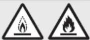 | WARNING | This symbol shows that this appliance used a flammable refrigerant. If the refrigerant is leaked and exposed to an external ignition source, there is a risk of fire. |
 | CAUTION | This symbol shows that the operation manual should be read carefully. |
 | CAUTION | This symbol shows that a service personnel should be handling this equipment with reference to the installation manual. |
 | CAUTION | This symbol shows that information is available such as the operating manual or installation manual. |
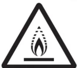
WARNING: Risk of fire
(for IEC 60335-2-40: 2018 only)
WARNING: Risk of fire
(for IEC/EN 60335-2-40
except IEC 60335-2-40: 2018)

NOTE
The symbols above are for R32 refrigerant system.
Any person who is involved with working on or breaking into a refrigerant circuit should hold a current valid certificate from an industry-accredited assessment authority, which authorises their competence to handle refrigerants safely in accordance with an industry recognised assessment specification.
Servicing shall only be performed as recommended by the equipment manufacturer. Maintenance and repair requiring the assistance of other skilled personnel shall be carried out under the supervision of the person competent in the use of flammable refrigerants.
These instructions are exclusively intended for qualified contractors and authorised installers
- Work on the refrigerant circuit with flammable refrigerant in safety group A2L may only be carried out by authorised heating contractors. These heating contractors must be trained in accordance with EN 378 Part 4 or IEC 60335-2-40, Section HH. The certificate of competence from an industry accredited body.
- Brazing/soldering work on the refrigerant circuit may only be carried out by contractors certified in accordance with ISO 13585 and AD 2000, Datasheet HP 100R. And only by contractors qualified and certified for the processes to be carried out. The work must fall within the range of applications purchased and be carried out in accordance with the prescribed procedures. Soldering/brazing work on accumulator connections requires certification of personnel and processes by a notified body according to the Pressure Equipment Directive (2014/68/EU).
• Work on electrical equipment may only be carried out by a qualified electrician. - Before initial commissioning, all safety relevant points must be checked by the particular certified heating contractors. The system must be commissioned by the system installer or a qualified person authorised by the installer.
Safety Warning
WARNING CONTENTS
Ensure Proper Earthing

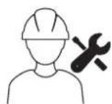
Professional Only
PROHIBITION SIGNS
No Laying
Inflammable Thing
No Strong Currents
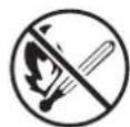
No Open Flame; Fire, Open Ignition Source and Smoking Prohibited

No Acid or Alkali Materials
1 Safety Precautions
DANGER
In the event of refrigerant leakage, smoking and open flames are prohibited. Disconnect the main power switch immediately, open windows to allow ventilation, keep away from the leakage point, and contact your local dealer or technical support to request a professional repair.
WARNING
Air conditioner installation must comply with local standards and electrical codes, and relevant instructions in this manual.
The appliance shall be stored in a well-ventilated area where the room size corresponds to the room area as specified for operation.
The appliance shall be stored in a room without continuously operating open flames (for example an operating gas appliance) and ignition sources (for example an operating electric heater).
The appliance shall be stored so as to prevent mechanical damage from occurring.
Do not use any liquid cleanser, liquefied cleanser, or corrosive cleanser to wipe this unit or spray water or other liquids on the unit. Otherwise, the plastic parts of the unit will become damaged and an electrical shock may occur. Disconnect the main power switch before cleaning and maintenance to avoid accidents.
Ask a professional to remove and reinstall the air conditioner.
Ask a professional for maintenance and repair assistance.
This air conditioner is classified as an "appliance which is not accessible to the general public".
The indoor unit shall be placed at a height not accessible to children, at least 2.5m above the ground.
Indoor unit
2.5m

CAUTION
This appliance is not intended for use by persons (including children) with reduced physical, sensory or mental capabilities, or lack of experience and knowledge, unless they have been given supervision or instruction concerning use of the appliance by a person responsible for their safety.
Children should be supervised to ensure that they do not play with the appliance.
The units are partial unit air conditioners, complying with partial unit requirements of this International Standard, and must only be connected to other units that have been confirmed as complying to corresponding partial unit requirements of this International Standard.

Electric Safety Requirements

WARNING
The air conditioner shall be installed according to the local wiring specifications.
Wiring work must be completed by qualified electricians.
The air conditioner must be well earthed. Specifically, the main switch of the air conditioner must have a reliable earthing cable.
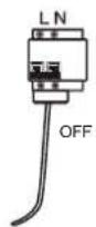
Before contacting wiring devices, cut off all the power supplies.
The user MAY NOT disassemble or repair the air conditioner. Doing so can be dangerous. In the event of a fault, immediately cut off the power and contact your local dealer or technical support.
A separate power supply that meets the rated parameter values must be provided for the air conditioner.
The fixed wiring to which the air conditioner is connected must be equipped with a power cut-off device that meets the wiring requirements.
The air conditioner's circuit board (PCB) is designed with a fuse to provide overcurrent protection.
The specifications of the fuse are printed on the circuit board.
NOTE: For the units with R32 refrigerant, only the blast-proof ceramic fuse can be used.


CAUTION
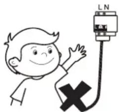
Under no circumstances should the earth wires of the power supply system be disconnected.
If the supply cord is damaged, it must be replaced by the manufacturer, its service agent or similarly qualified persons in order to avoid a hazard.
Do not use a damaged power supply cable and replace it if it is damaged.
When the air conditioner is used for the first time or is in a power-off state for a long time, it needs to be connected to the power supply and warmed up for at least 12 hours before use.
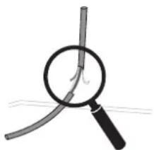
natural_image
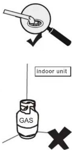
Simple line drawing of a magnifying glass over a curved tube, no text or symbols presentThe following applies to R32 refrigerant systems.
Prior to beginning work on systems containing flammable refrigerants, safety checks are necessary to ensure that the risk of ignition is minimized.
For repair to the refrigerating system, the following precautions shall be complied with prior to conducting work on the system.
Work shall be undertaken under a controlled procedure so as to minimise the risk of a flammable gas or vapour being present while the work is being performed.
All maintenance staff and others working in the local area shall be instructed on the nature of work being carried out. Work in confined spaces shall be avoided. The area around the workspace shall be sectioned off. Ensure that the conditions within the area have been made safe by control of flammable material.
The area shall be checked with an appropriate refrigerant detector prior to and during work, to ensure the technician is aware of potentially flammable atmospheres.
Ensure that the leak detection equipment being used is suitable for use with flammable refrigerants, i.e. non-sparking, adequately sealed or intrinsically safe.
If any hot work is to be conducted on the refrigeration equipment or any associated parts, appropriate fire extinguishing equipment shall be available to hand. Have a dry powder or CO_2 fire extinguisher adjacent to the charging area.
No person carrying out work in relation to a refrigeration system which involves exposing any pipe work that contains or has contained flammable refrigerant shall use any sources of ignition in such a manner that it may lead to the riskof fire or explosion.
All possible ignition sources, including cigarette smoking, should be kept sufficiently far away from the site of installation, repairing, removing and disposal, during which flammable refrigerant can possibly be released to the surrounding space.
Prior to work taking place, the area around the equipment is to be surveyed to make sure that there are no flammable hazards or ignition risks. “No Smoking” signs shall be displayed.
Ensure that the area is in the open or that it is adequately ventilated before breaking into the system or conducting any hot work. A degree of ventilation shall continue during the period that the work is carried out. The ventilation should safely disperse any released refrigerant and preferably expel it externally into the atmosphere.
Where electrical components are being changed, they shall be fit for the purpose and to the correct specification. At all times the manufacturer's maintenance and service guidelines shall be followed. If in doubt consult the manufacturer's technical department for assistance.
The following checks shall be applied to installations using flammable refrigerants:
– the charge size is in accordance with the room size within which the refrigerant containing parts are installed;
– the ventilation machinery and outlets are operating adequately and are not obstructed;
- if an indirect refrigerating circuit is being used, the secondary circuit shall be checked for the presence of refrigerant;
– marking to the equipment continues to be visible and legible. Markings and signs that are illegible shall be corrected;
– refrigeration pipe or components are installed in a position where they are unlikely to be exposed to any substance which may corrode refrigerant containing components, unless the components are constructed of materials which are inherently resistant to being corroded or are suitably protected against being so corroded.
Repair and maintenance to electrical components shall include initial safety checks and component inspection procedures.
If a fault exists that could compromise safety, then no electrical supply shall be connected to the circuit until it is satisfactorily dealt with. If the fault cannot be corrected immediately but it is necessary to continue operation, an adequate temporary solution shall be used. This shall be reported to the owner of the equipment so all parties are advised.
Initial safety checks shall include:
-that capacitors are discharged: this shall be done in a safe manner to avoid possibility of sparking;
-that no live electrical components and wiring are exposed while charging, recovering or purging the system;
-that there is continuity of earth bonding.
During repairs to sealed components, all electrical supplies shall be disconnected from the equipment being worked upon prior to any removal of sealed covers, etc. If it is absolutely necessary to have an electrical supply to equipment during servicing, then a permanently operating form of leak detection shall be located at the most critical point to warn of a potentially hazardous situation.
Particular attention shall be paid to the following to ensure that by working on electrical components, the casing is not altered in such a way that the level of protection is affected. This shall include damage to cables, excessive number of connections, terminals not made to original specification, damage to seals, incorrect fitting of glands, etc.
Ensure that seals or sealing materials have not degraded such that they no longer serve the purpose of preventing the ingress of flammable atmospheres.
Replacement parts shall be in accordance with the manufacturer's specifications.
Do not apply any permanent inductive or capacitance loads to the circuit without ensuring that this will not exceed the permissible voltage and current permitted for the equipment in use.
Intrinsically safe components are the only types that can be worked on while live in the presence of a flammable atmosphere. The test apparatus shall be at the correct rating.
Replace components only with parts specified by the manufacturer. Other parts may result in the ignition of refrigerant in the atmosphere from a leak.
Check that cabling will not be subject to wear, corrosion, excessive pressure, vibration, sharp edges or any other adverse environmental effects. The check shall also take into account the effects of ageing or continual vibration from sources such as compressors or fans.
When breaking into the refrigerant circuit to make repairs – or for any other purpose – conventional procedures shall be used. However, it is important that best practice is followed.
Since flammability is a consideration. The following procedure shall be adhered to:
- remove refrigerant;
• purge the circuit with inert gas; - evacuate;
• purge again with inert gas; - open the circuit by cutting or brazing.
The refrigerant charge shall be recovered into the correct recovery cylinders. The system shall be “flushed” with OFN to render the unit safe. This process may need to be repeated several times. Compressed air or oxygen shall not be used for this task.
Flushing shall be achieved by breaking the vacuum in the system with OFN and continuing to fill until the working pressure is achieved, then venting to atmosphere, and finally pulling down to a vacuum.
This process shall be repeated until no refrigerant is within the system. When the final OFN charge is used, the system shall be vented down to atmospheric pressure to enable work to take place.
This operation is absolutely vital if brazing operations on the pipe-work are to take place.
Ensure that the outlet for the vacuum pump is not close to any ignition sources and there is ventilation available.
Ensure that contamination of different refrigerants does not occur when using charging equipment. Hoses or lines shall be as short as possible to minimise the amount of refrigerant contained in them.
Prior to recharging the system it shall be pressure tested with OFN.
DD.12 Decommissioning:
Before carrying out this procedure, it is essential that the technician is completely familiar with the equipment and all its detail. It is recommended good practice that all refrigerants are recovered safely. Prior to the task being carried out, an oil and refrigerant sample shall be taken in case analysis is required prior to re-use of reclaimed refrigerant. It is essential that electrical power is available before the task is commenced.
a) Become familiar with the equipment and its operation.
b) Isolate system electrically.
c) Before attempting the procedure ensure that:
- mechanical handling equipment is available, if required, for handling refrigerant cylinders;
- all personal protective equipment is available and being used correctly;
- the recovery process is supervised at all times by a competent person;
- recovery equipment and cylinders conform to the appropriate standards.
d) Pump down refrigerant system, if possible.
e) If a vacuum is not possible, make a manifold so that refrigerant can be removed from various parts of the system.
f) Make sure that cylinder is situated on the scales before recovery takes place.
g) Start the recovery machine and operate in accordance with manufacturer's instructions.
h) Do not overfill cylinders. (No more than 80 % volume liquid charge).
i) Do not exceed the maximum working pressure of the cylinder, even temporarily.
j) When the cylinders have been filled correctly and the process completed, make sure that the cylinders and the equipment are removed from site promptly and all isolation valves on the equipment are closed off.
k) Recovered refrigerant shall not be charged into another refrigeration system unless it has been cleaned and checked.
Equipment shall be labelled stating that it has been de-commissioned and emptied of refrigerant. The label shall be dated and signed. Ensure that there are labels on the equipment stating the equipment contains flammable refrigerant.
When removing refrigerant from a system, either for servicing or decommissioning, it is recommended good practice that all refrigerants are removed safely.
When transferring refrigerant into cylinders, ensure that only appropriate refrigerant recovery cylinders are employed. Ensure that the correct number of cylinders for holding the total system charge are available. All cylinders to be used are designated for the recovered refrigerant and labelled for that refrigerant (i.e. special cylinders for the recovery of refrigerant). Cylinders shall be complete with pressure relief valve and associated shut-off valves in good working order. Empty recovery cylinders are evacuated and, if possible, cooled before recovery occurs.
The recovery equipment shall be in good working order with a set of instructions concerning the equipment that is at hand and shall be suitable for the recovery of flammable refrigerants. In addition, a set of calibrated weighing scales shall be available and in good working order. Hoses shall be complete with leak-free disconnect couplings and in good condition. Before using the recovery machine, check that it is in satisfactory working order, has been properly maintained and that any associated electrical components are sealed to prevent ignition in the event of a refrigerant release. Consult manufacturer if in doubt.
The recovered refrigerant shall be returned to the refrigerant supplier in the correct recovery cylinder, and the relevant Waste Transfer Note arranged. Do not mix refrigerants in recovery units and especially not in cylinders.
If compressors or compressor oils are to be removed, ensure that they have been evacuated to an acceptable level to make certain that flammable refrigerant does not remain within the lubricant. The evacuation process shall be carried out prior to returning the compressor to the suppliers. Only electric heating to the compressor body shall be employed to accelerate this process. When oil is drained from a system, it shall be carried out safely.
Warning: disconnect the appliance from its power source during service and when replacing parts.
These units are partial unit air conditioners, complying with partial unit requirements of this International Standard, and must only be connected to other units that have been confirmed as complying to corresponding partial unit requirements of this International Standard.
Operation
1 Operation Precautions

WARNING
If the unit will be not used for a long time, disconnect the main power switch. Otherwise, an accident may occur.
The installation height of the air conditioner shall be at least 2.5m above the ground to avoid the following risks:
- Touching of moving or live parts, such as fans, motors, or louvers, by a non professional.
Running parts may cause harm to you or transmission assemblies may become damaged.
- Getting too close to the air conditioner may reduce the level of comfort.
Do not let children play with the air conditioner. Otherwise, an accident may occur.
Do not expose the indoor units or controller to moisture or water as this may cause short circuiting or fire.
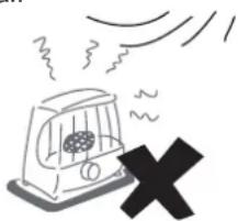
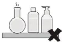
Do not place any appliance that uses an open flame in the direct air supply of the air conditioner as it could interfere with the combustion of the appliance.
Do not use or store flammable gases or liquids such as natural gas, hair spray, paint or gasoline near the air conditioner. Otherwise, a fire may occur.
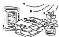
To avoid causing harm, do not place animals or plants directly in front of the air conditioner's air supply.
In the event of abnormal conditions such as abnormal noise, smell, smoke, temperature rise, and electric leakage, please cut off the power immediately, and then contact your local dealer or air conditioner customer service center. Do not repair the air conditioner by yourself.
Do not place flammable sprayers near the air conditioner or spray it directly at the air conditioner. Otherwise, a fire may occur.
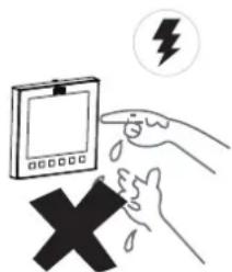
Do not place a container of water on the air conditioner. If immersed in water, the air conditioner's electrical insulation will weaken, resulting in electrical shock.
After long-term use, confirm whether the installation platform has become worn. If it is worn, the unit could fall, causing injury.
Do not operate the switch with wet hands, as this may result in electric shock.
When servicing the air conditioner, be sure to turn off the air conditioner and cut off the power supply. Otherwise, the high-speed operation of the internal fan will cause injury.
Do not use fuses like iron or copper wire other than those with the specified capacity. Otherwise, a malfunction or fire may occur. The power supply must use the special circuit of the air conditioner at the rated voltage.
Do not place valuables under the air conditioner. Air conditioner condensation problems may damage the valuables.
When the air conditioner needs to be moved and re-installed, please entrust the local dealer or a professional technician to operate it.
natural_image
Simple line drawing of a car with exhaust smoke and a black 'X' symbol (no text or labels)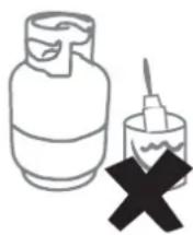

CAUTION
To use the unit normally, please follow the "Operation" section in this manual. Otherwise, the internal protection may be triggered, the unit may begin to drip, or the unit's cooling and heating effects may be impacted.
The room temperature should be set properly, especially when there are elderly, children, or patients in the room.
Lightning or the starting and stopping of large electrical equipment in nearby factories may cause misoperation of the air conditioner. Please turn off the main power switch for a few seconds, and then restart the air conditioner.
To avoid accidental resetting of the thermal circuit breaker, the air conditioner cannot be powered by an external switching device such as a timer or connected to a circuit that is turned on and off by a common component timer.
Check whether the air filter is installed properly. Confirm that the inlet and outlet ports of the indoor unit/outdoor unit are not blocked.
If the air conditioner will not be used for a long time, please clean the air filter before you start the air conditioner. Otherwise, dust and mold on the filter could contaminate the air or produce an unpleasant odor. For more details, please refer to the section "Maintenance and Service".
natural_image
Simple line drawing of a faucet spraying water into a grid-patterned container (no text or symbols)
Optimum Operation
As cold air sinks and hot air rises, to improve the cooling and heating effects, it is recommended to set the angle of the lover and ceiling to between 40^ to 70^ during cooling and heating.
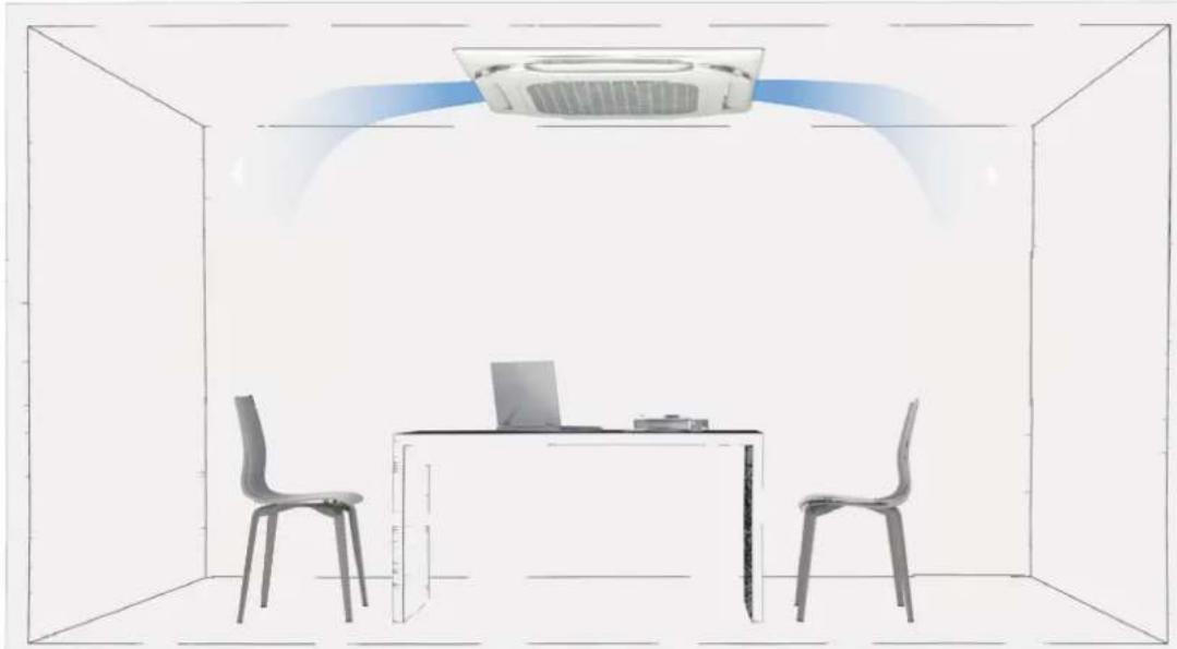
natural_image
Interior view of a room with two chairs, a laptop at a desk, and a ceiling-mounted air conditioner unit (no text or symbols visible)
CAUTION
Long-term air output at a 40^ angle may cause condensation on the surface of the louver. It is recommended to turn on the anti-condensation function through the wired controller to alleviate this situation.
Operating Range
Use the unit in the following temperature and humidity ranges for safe and effective operation.
| Cooling | Indoor temperature | 16~32°C |
| Indoor humidity | ≤80%(When the humidity exceeds 80%, long-time operation of the indoor unit may cause dew condensation on the surface of the indoor unit, generate mist-like cold air from the air outlet or water dripping out of the unit.) | |
| Heating | Indoor temperature | 15~30°C |

NOTE
If it exceeds this operating range, safety devices may be put in action and the unit may not operate.

Symptoms That Are Not Faults
Normal Protection Of The Air Conditioner
During operation, the following phenomena are normal and do not require maintenance.

When the power switch is on, the air conditioner starts 3-5 minutes after it is turned ON again in case it was turned off just before.
In heating mode (including heating in automatic mode), when the indoor heat exchanger does not reach a certain temperature, the indoor fan temporarily shuts off, or runs in Low mode until the heat exchanger heats up to prevent the blowing of cold air.
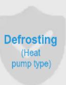
When the outdoor temperature is low and the humidity is high, the outdoor unit's heat exchanger may become frosted, which may reduce the heating capacity of the air conditioner. If this occurs, the air conditioner will stop heating, enter automatic defrosting mode, and return to heating mode after defrosting has been completed.
During the defrosting, the outdoor fan stops running and the indoor fan runs using the anti-cold air protection function.
The defrosting operation time varies depending on the outdoor temperature and the degree of frosting. It generally takes 2 to 10 minutes.
During the defrosting process, the outdoor unit may emit steam due to the rapid defrosting, which is normal.

When the indoor unit detects high humidity, the air conditioner will adjust the louver angle and the fan speed to prevent condensation and avoid dripping. (If a third-party panel is selected, this function is not available.)
The Following Symptoms Are Not System Malfunctions
The following phenomena are normal during operation of the air conditioner. They can be solved according to the instructions below or do not need to be solved.
■ The indoor unit emits white mist
① When humidity is high during cooling mode, white mist may appear due to the humidity and the temperature difference between the air inlet and outlet.
② When the air conditioner is switched to heating mode after defrosting, the indoor unit discharges the moisture generated from defrosting as steam.
■ The indoor unit blows dust
When filter is very dirty, dust may enter the indoor unit and be blown out.
■ The indoor unit emits odor
The indoor unit absorbs the odors of rooms, furniture or cigarettes, etc., and disperses the odors during operation. It is advised to have the air conditioner cleaned and maintained regularly by professional technicians.
Water drips
When the indoor humidity is high, condensation and water may drip out of the unit.
■ "Self-cleaning" sound of icing
During self-cleaning, there may be a slight clicking sound from the melting thin ice about 10 minutes.
Noise of Indoor unit
① A continuous low "hissing" sound is heard when the system is in "Auto", "Cool", "Dry", and "Heat" modes. This is the sound of refrigerant gas flowing through both indoor and outdoor units.
② A "hissing" sound is heard at the start or immediately after stopping operation or defrost operation. This is the noise of refrigerant caused by flow change.
③ A "zeen" sound is heard immediately after the power supply is turned on. The electronic expansion valve inside an indoor unit starts working and makes the noise. it will reduce in about one minute.
④ A continuous low "shah" sound is heard when the system is in cooling mode, dry mode or at a stop. When the drain pump (optional accessories) is in operation, this noise is heard.
⑤ A "pishi-pishi" squeaking sound is heard when the system stops after heating operation. Expansion and contraction of plastic parts caused by temperature change make this noise.
⑥ A low "sah", "choro-choro" sound is heard while the indoor unit is stopped. When another indoor unit is in operation, this noise is heard. In order to prevent oil and refrigerant from remaining in the system, a small amount of refrigerant is kept flowing.
■ Switching from cooling/heating (not available for cooling only units) mode to fan only mode
When the indoor unit reaches the set temperature, the air conditioner controller automatically stops the compressor operation and switches to the fan only mode. When the room temperature rises (in cooling mode) or falls (in heating mode) to a certain level, the compressor is restarted and cooling or heating operation is resumed.
In winter, the outdoor temperature is low, and heating effects may be decreased
① In heating mode, the air-conditioning system absorbs heat from the outdoor air and releases heat to the indoor side. When the outdoor temperature is low, less heat is released. This is the principle of heat pump.
② When the outdoor temperature is extremely low, the heating capacity of the air conditioner decreases, and other heating equipment may need to be added.
■ No heating or cooling permissions
For the same air conditioning system, if outdoor unit operates in changeover mode, the wired controller of VIP indoor unit allows users to select modes supported by the indoor units, while the wired controllers of other indoor units displays the icon of " No permission". In this case, other indoor units can only operate in the same mode as the VIP indoor unit.
4 Display Panel
88.8
Display functions:
① In Standby mode, the main interface displays “---”.
② When starting up in Cooling or Heating mode, the main interface displays the set temperature. In Fan mode, the main interface displays the indoor temperature. In Dry mode, the main interface displays the set temperature, and when the humidity* is set, the set humidity value is displayed on the wired controller.
③ The light display on the main interface can be turned on or off through the light button on the remote controller.
④ When the system fails or runs in a special mode, the main interface displays the error code or the operating status codes. For details, see the section "Error Codes and definitions".

NOTE
Humidity*: The humidity control functions is customized.
Some display functions are available only for certain indoor unit and outdoor unit models, wired controllers, and display panels. For more information, please consult your local dealer or technical support.
5 Disposal
Components and accessories from the units are not part of ordinary domestic waste.
Complete units , compressors, motors etc. are only to be disposed of via qualified disposal specialists.
This unit uses hydrofluorocarbon which is only be disposed of via qualified disposal specialists.
1 Installation Precautions

WARNING
Make sure to carry out the installation according to local legislation.
Ask your local dealer or professionals to install the product.
This unit must be installed by pqualified persons. Users MAY NOT install the unit themselves; otherwise, faulty operations may cause the risks of fire, electrical shock, injury, or leakage, which could harm you or others or damage the air conditioner.
Never modify or repair the unit on your own.
Otherwise, a fire, electric shock, injury or water leakage may occur. Get your local dealer or a professional to do so.

Make sure that the residual current device is installed.
The residual current device must be installed. Failure to install it may result in electric shock.
When powering the unit, follow the regulations of the local electric companies.
Make sure that the unit is earthed reliably in accordance with laws. If the earthing is not completed correctly, it may cause electrical shock.
When moving, disassembling or reinstalling the air conditioner, get the assistance of your local dealer or a professional.
If installed improperly, fire, electrical shock, injury, or water leakage may occur.
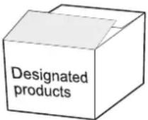
Use the optional accessories specified by local dealer.
The installation of these accessories must be carried out by professionals. Improper installation may cause fire, electrical shock, water leakage and other hazards.
Use only power supply cable and communication cables that meet specification requirements. Properly connect all the wiring to make sure that no external forces are acting on the terminal blocks, power supply cable and communication cables. Improper wiring or installation may cause a fire.
The air conditioner must be earthed. Check whether the earth line is securely connected or broken. Do not connect the earth line to gas cans, water piping, lightning rods or telephone earth lines.
The main power switch of the air conditioner should be put in a position that is out of the reach of children.
It should not be obstructed by flammable objects such as curtains.
Open flames are prohibited when refrigerant leaks are present.
If the air conditioner is not cooling/heating properly, this may be caused by a refrigerant leak. If this occurs, contact your local dealer or a professional. The refrigerant in the air conditioner is safe, and usually does not leak.
If there is refrigerant leakage in the room, it is easy for a fire to occur after contact with the heating units of the heater/electric stove/stove. Please disconnect the power supply of the air conditioner, extinguish the flames of appliances that produce a flame, and open the windows and doors of the room to allow ventilation and ensure that the concentration of refrigerant leakage in the room does not exceed a critical level; keep away from the leakage point, and contact the dealer or professional personnel.
After the refrigerant leakage is repaired, do not start the product until the maintenance personnel confirms that the leakage is well repaired.
Before and after installation, exposing the unit to water or moisture will cause electrical short circuit.
Do not store the unit in a humid basement or expose it to rain or water.
Make sure the installation base and lifting are robust and reliable;
Insecure installation of the base may cause the air conditioner to fall, leading to an accident. Take into full consideration the effects of strong winds, typhoons and earthquakes, and reinforce the installation.
Check whether the drain pipe can drain the water smoothly.
Improper installation of the pipeline may lead to water leakage, damaging furniture, electric appliances, and the carpet.
After installation, check whether the refrigerant is leaking.
Do not install the product in a location where there is a danger of flammable gas leaks.
In the event of leakage of combustible gas, the combustible gas surrounding the indoor unit may cause a fire.

CAUTION
Keep the indoor unit, outdoor unit, power supply cable, and connecting wires at least 1m away from the high-power radio equipment, to prevent electromagnetic interference and noise. For some electromagnetic waves, it is not enough to prevent noise even at a distance of more than 1m.
In a room equipped with fluorescent lamps (rectifier type or fast start type), the signal transmission distance of the remote controller (wireless) may not reach the predetermined value. Install the indoor unit as far away from the fluorescent lamp as possible.
Do not touch the fins of the heat exchanger, as this could cause injury.
For safety, please dispose of the packing materials properly.
Nails and other packaging materials may cause personal injury or other risks. Tear up the plastic packaging bag and dispose of it properly to prevent children from playing with it, leading to suffocation.
Do not cut off the power supply immediately after the indoor unit stops running.
Some parts of the indoor unit like the valve body and water pump are still in operation. Please wait for at least 5 minutes before cutting off the power supply. Otherwise, water leakage and other faults may occur.
If the temperature and humidity in the ceiling mezzanine may exceed 30°C RH80%, please put insulation material on the unit.
Please use glass wool or foamed polyethylene as insulation material, the thickness of which is required to be 10mm or more, and can be stored in the ceiling opening.
For evaporating units and condensing units, the instructions or markings shall include a wording to assure that the maximum operating pressure is considered when connecting to any condenser unit or evaporator unit.
For evaporating units, condensing units and condenser units, the instructions or markings shall include refrigerant charging instructions.
A warning to assure that partial units shall only be connected to an appliance suitable for the same refrigerant.
This unit is a partial unit air conditioner, complying with partial unit requirements of this International Standard, and must only be connected to other units that have been confirmed as complying to corresponding partial unit requirements of this International Standard.
The electrical interfaces shall be specified with purpose, voltage, current, and safety class of construction.
The SELV connection points, if provided, are to be clearly indicated in the instructions.
The connection point should be marked with the “read the instructions” symbol per ISO 7000-0790 (2004-01) and the Class III symbol according to IEC 60417-5180 (2003-02).
For R32 Refrigerant only.
This unit is equipped with a refrigerant leak detector for safety. To be effective, the unit must be electrically powered at all times after installation, other than when servicing.
If any supplemental unit is employed to detect leaked refrigerant, such unit shall also apply this marking or be accompanied by such instructions.
Precautions For Transporting And Lifting The Air Conditioner
①
Before transporting the air conditioner, determine the path that will be used to move it to the installation site.
②
Do not unpack the air conditioner until it is transported to the installation site.
③
When unpacking and moving the air conditioner, must hold the Lifting Lugs and do not apply force to other parts, especially the refrigerant piping, drain pipe and plastic accessories, so as to avoid damaging the air conditioner and causing personal injury.
④
Before installing the air conditioner, make sure that the refrigerant specified on the nameplate is being used.
Forbidden Installation Sites

WARNING
Do not install or use the air conditioner in the following places:
A place filled with mineral oil, fumes or mist, like a kitchen.
Plastic parts will age and the heat exchanger will become dirty, eventually causing the air conditioner performance to deteriorate or leak water.
Connecting pipes and copper welds will be corroded, resulting in refrigerant leakage.
A place where there are corrosive gases, such as acid or alkaline gases.
Connecting pipes and copper welds will be corroded, resulting in refrigerant leakage.
A place exposed to combustible gases and using volatile combustible gases such as diluent or gasoline.
The electronics in the air conditioner may cause the surrounding gas to ignite.
A place where there is equipment emitting electromagnetic radiation.
The control system will fail and the air conditioner will not function properly.
A place where there is a high salt content in the air like a coastal area.
Do not use the air conditioner in an environment where an explosion may occur.
The unit cannot be installed on moving vehicles such as truck and ship.
Factors with major voltage fluctuations in the power supplies.
Other special environmental conditions.

CAUTION
Air conditioner units of this series are designed to provide comfort. Don't install the unit in mechanical rooms and rooms with precision instruments, food, plants, animals, or artwork.
Avoid installation in an environment with a lot of organic compounds such as ink and siloxane.
The total refrigerant charge in the system cannot exceed the requirements for minimum room size of the smallest one that is served.

NOTE
Wooden buildings, newly renovated houses, and frequent use of disinfectants may contain acidic components in the air, such as formic acid, acetic acid, and hypochlorous acid, which can corrode copper pipes and solder joints, leading to refrigerant leaks.
Factories, chemical plants, livestock farms, vegetable markets, sewage pits, and other environment may contain sulfides, acid gases such as sulfur dioxide, ammonia, and chlorides in the air, which can corrode copper pipes and solder joints, leading to refrigerant leaks.
Please contact a dealer for assistance.

Keep the air-conditioning return air away from direct exposure to the sun in the room.
The indoor unit should not be lifted in the places like load-bearing beams and columns that affect the structural safety of the house.
The wired controller and the indoor unit should be in the same installation space; otherwise, the sampling point setting of the wired controller needs to be changed.
Choose a site that fully complies with the following conditions and user requirements to install the air conditioning unit:

There is enough space for installation and maintenance.
The ceiling is level, and the structure is strong enough to support the indoor unit. If necessary, take measures to reinforce the unit's stability.
Airflow in/out of the machine is not obstructed, and the external air exerts minimum impact.
It is easy to supply airflow to every corner of the room.
It is easy to drain fluids from the connected piping and water drain piping.
There is no direct heat radiation.
Avoid installation in narrow spaces or where there are more stringent noise requirements.
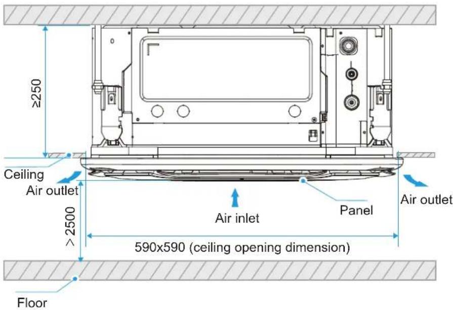
The indoor unit needs to be installed at a position greater than 2.5m and less than 3.5m from the ground.
Condensate water can be discharged smoothly.
The length of the piping between the indoor and outdoor units is within the permitted range. Refer to the Installation and Operation Manual attached with the outdoor unit.
(Unit: mm)
(Unit: mm)
Installation layout
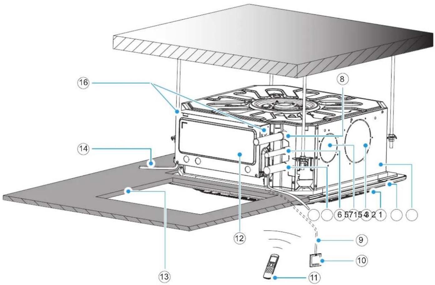
① Indoor unit
④ Expanded outlet
⑦ Gas pipe
⑩ Wired controller (optional)
⑬ Access hole
⑯ North American inlet hole (two)
* To be purchased separately on site.
② Panel (optional)
⑤ Fresh air inlet
⑧ Drain pipes
⑪ Remote controller (optional)
⑭ *Power cable and earth wires
③ Air outlet
⑥ Liquid pipe
⑨ *Connection wires
⑫ Electric control box
⑮ *Communication wiring

NOTE
Panels, wired controllers, and remote controllers are available in various models. All the optional accessories should be from local dealer.
For optional accessories such as wired controllers, please refer to the manuals of these accessories.
All the figures in the manual explain only the general appearance and functions of the product. The appearance and functions of the purchased product may not be completely consistent with those listed in the figures. Please refer to the actual product.
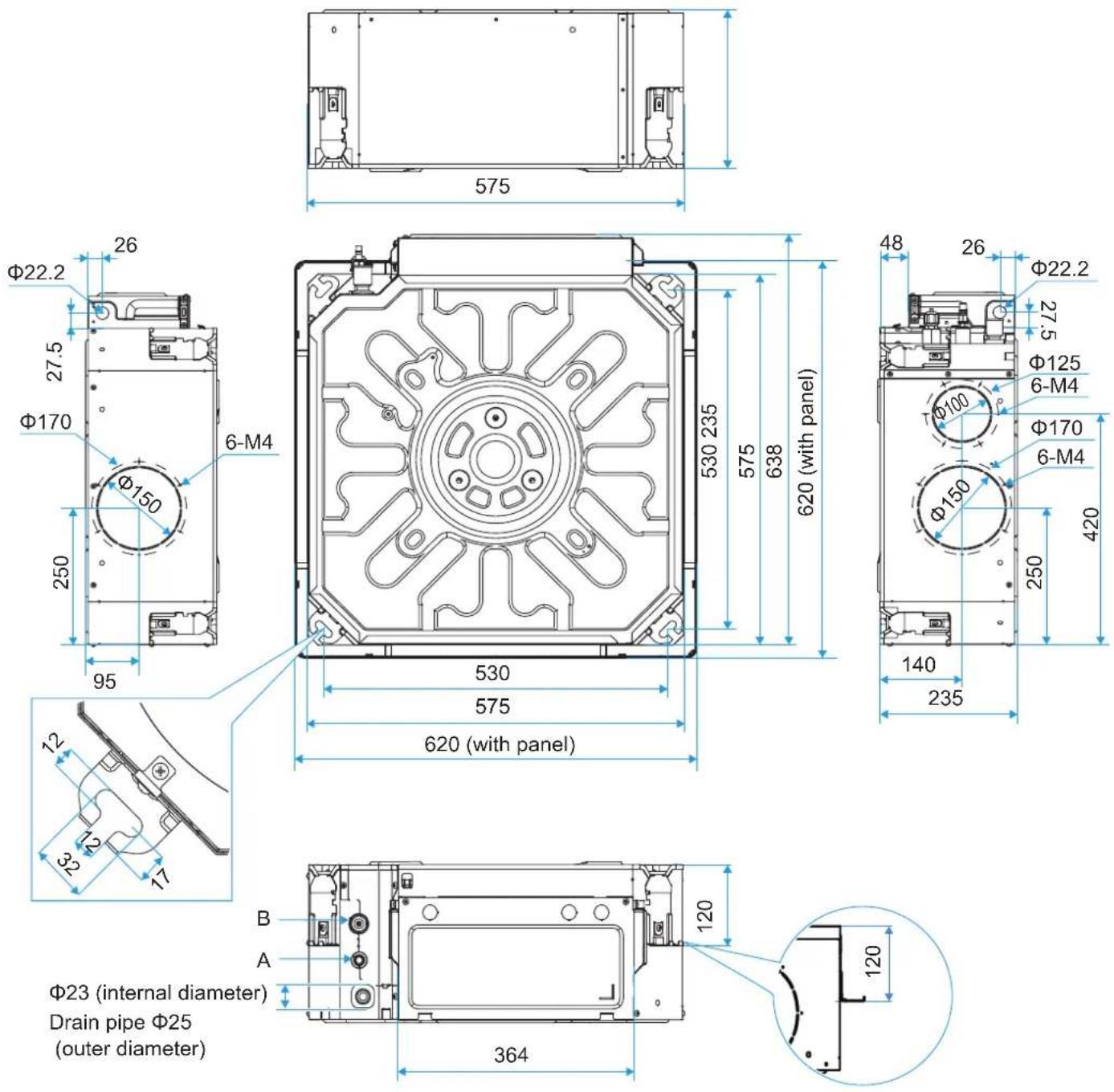
Φ23 (internal diameter)
Drain pipe Φ25
(outer diameter)
| Capacity (kW) | A: Connect to refrigerant piping (liquid side) | B: Connect to refrigerant piping (gas side) |
| kW ≤ 5.6 | 6.35 | 12.7 |
| 5.6 < kW ≤ 6.3 | 9.52 | 15.9 |
2 Installation Materials
Accessories
List of accessories
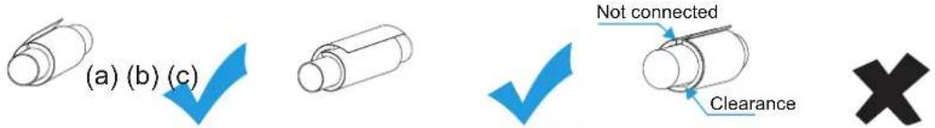
| Installation And Operation Manual X 1(Make sure to hand it over to the user) | Flare Nut X 2For use in the installation of connecting pipe (the quantity is one for models with a process pipe) | Cable Tie X 4To tighten the drain hose tightly to the drainage outlet and PVC piping of the indoor unit. | Thermal Insulation Pipe X 2Used for insulation and anti-condensation at pipe connections. |

NOTE
When installing the insulation pipe on site, please cut it according to the actual needs. (Either method (a) or (b) is OK. Method (c) is incorrect. There must be no gap between the insulation pipe and connecting pipe.)
Check the accessory kit for the above items and contact your local dealer for any missing items.
Do not throw away any accessories that may be required for installation until the installation is complete.
Customers are free to choose to buy wired controllers, remote controllers (with a seven-speed wind controller) and other optional accessories.
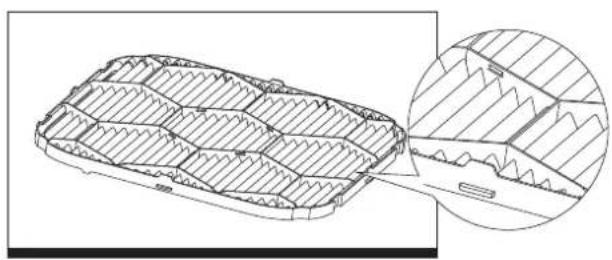
Except primary efficiency filters, medium efficiency filters are optional.
Primary filter Medium efficiency filter
natural_image
Technical line drawing of a rectangular mechanical component with internal grooves, shown with an inset magnified detail (no text or symbols)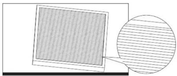
natural_image
Diagram showing a grid-patterned square on the left and a magnified circular view of parallel lines on the right (no text or symbols)Locally Purchased Accessories
List of accessories
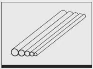
| Copper PipeUsed to connect the indoor refrigerant piping. | PVC Water Drain PipeUsed to drain the condensed water from the indoor unit. | Thermal Insulation PipeUsed to prevent pipe condensation. | Expansion Bolt (M10)x4Used to install the indoor unit. | Suspension Bolt (M10)x4Used to install the indoor unit. |
 | Connecting pipe (Unit: mm) | ||
| Capacity(kW) Piping | Liquid side | Gas side | |
| kW≤5.6 | Φ6.35×0.75 | Φ12.7×0.75 | |
| 5.6< kW≤6.3 | Φ9.52×0.75 | Φ15.9×1.0 | |
| Remarks | For connection of the indoor unit refrigerant system, it is recommended to use a soft copper tube (T2M), with the length selected according to the actual situation. | ||
 | PVC water drain pipe | 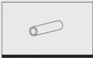 | Thermal insulation pipe |
| This is used as the indoor unit's drain pipe, 25mm in external diameter. The length is determined according to actual needs. | The thickness of the insulation pipe for the connecting pipe is usually 15mm or above; and the thickness of the insulation pipe for the rigid polyethylene plastic tube is usually 10mm or above. If the pipe is used in a closed humid area, the thickness should be increased. | ||

NOTE
The materials necessary for onsite installation of the connecting pipe, drain pipe, lifting screw, various fasteners (pipeline bracket, Victaulic connector, screw, etc.), power supply cable, signal line, etc. need to be purchased by the installer. The materials and specifications must comply with the corresponding local or industrial standards.
Insulation Material Requirements
| Connecting pipe insulation | The insulation work should only be carriedout after the successful completion of the air tight test.Use polyethylene foam as insulationmaterial, fire rating class is B1 and heat resistance is over 120°C.Thickness of the insulation pipe:1. When the pipe diameter is equal to orgreater than 15.9mm, the insulation thickness is at least 20mm.2. When the pipe diameter is equal to orsmaller than 12.7mm, the insulation thickness is at least 15mm.In cold climates, for heating application,the insulation thickness of outdoor refrigerant pipe is at least 40mm, theinsulation thickness of indoor refrigerant pipe is at least 20mm.Use glue to seal the jointed areas of thermalinsulation pipes, and then wrap them with electrical tape with a width of notless than 50mm to ensure the connection is sealed.Make sure the insulation between therefrigerant pipes and the Indoor unit are entire to prevent the condensation. |
| Drain pipe insulation | After the drainage test shows that thereare no leaks, carry out the insulation of the drain piping.Drain pipe connection hole shall beinsulated to prevent condensation.Drain piping passing indoors shall beinsulated to prevent condensation, and insulation sleeves should be thicker than 10mm.Use glue to seal the jointed areas ofthermal insulation pipes.The head of the metal clamp should be atthe top, and metal clamp should be well insulated. |

NOTE
The materials and specifications of insulation materials must meet national or industry standards.
3 Preparations Before Installation
Unpacking Check
① After unpacking, check whether the packing materials are in good condition, whether the accessories that come with the product are complete, whether the air conditioner is intact, whether the surfaces of the heat exchanger and other parts are not worn, and whether there are oil stains on the stop valves of the unit.
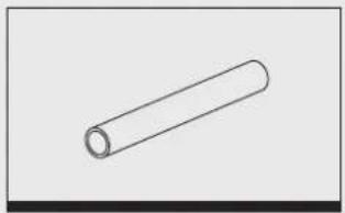
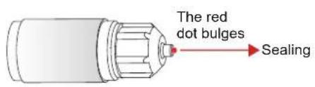
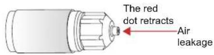
② Check the two sealing nuts of the refrigerant pipe, and observe whether the red dot on the surface of the sealing nut of the gas pipe bulges. If it bulges, the refrigerant system is well sealed; if it retracts, it is leaking, and need to contact local dealer.
③ Check the model before installation.
④ After indoor unit and outdoor unit inspection, pack them with plastic bags to avoid intake of foreign matters.
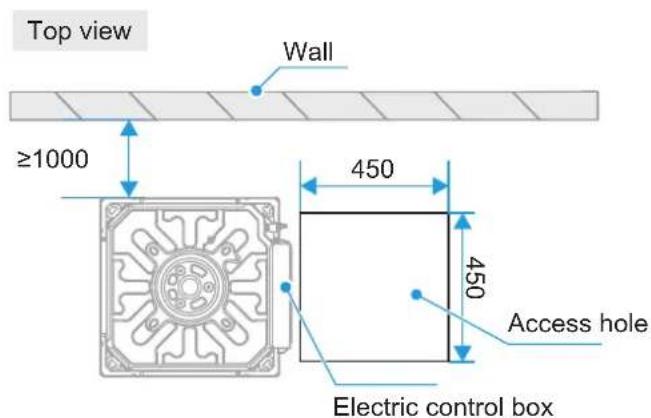
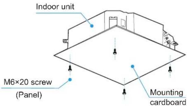
Indoor Unit Positioning
Determine the positions of the air conditioning unit and suspension bolts.
① Determine the suspension position of the indoor unit according to the design drawing.
② Draw lines to locate the drilling positions of the suspender bolts according to the mounting cardboard.
③ Make an access hole on the electric control box side (recommended size: 450×450mm).
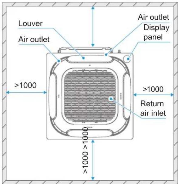
④ There shall be no obstacles within 1000mm of the return air inlet.
⑤ It is suggested to use an infrared ray locator for line drawing.
(Unit: mm)
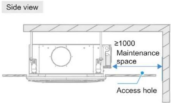
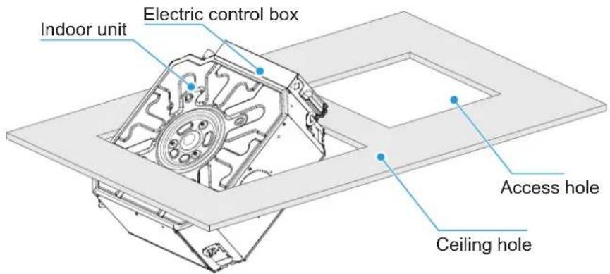
Determine The Positions Of The Ceiling Opening, The Unit And The Suspension Bolts
1 Cut a hole with a size of 590mm x 590mm.

NOTE
Align the center of the ceiling box with that of the indoor unit of the air conditioner.
2 Use the holes in the mounting cardboard to determine the positions of mounting holes.
3 When installing the air conditioner on a new ceiling, affix cardboard to the indoor unit of the installed air conditioner as a reference to determine the size, location, and center of the ceiling box.

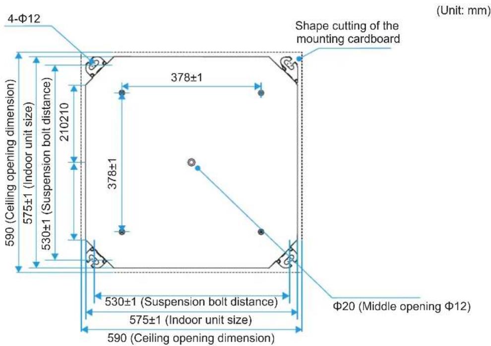
CAUTION
Evenly adjust the four hex nuts to make sure that the indoor unit of the air conditioner is level.
When the air conditioner is to be fixed onto the ceiling with a frame:
The horizontal distance of the overlapping part of the ceiling and decoration panel must be more than 10mm. The distance between the indoor unit and the ceiling must be within 12mm. If the distance is greater than 15mm, retrofit the ceiling.
If Necessary, Cut Out The Required Openings For Installation On The Ceiling (Where There Is An Existing Ceiling).
For the dimensions of ceiling openings, refer to the following figure.
(Unit: mm)

CAUTION
Before connecting the indoor unit piping and wiring, connect the refrigerant piping, drain pipes, wired controller wires (not required when using a wireless remote controller), and the connection wires, power supply cable, and earth wires between the indoor unit and outdoor unit (please refer to piping and wiring instructions) so that it can be connected to the indoor unit immediately after installation.
To cut ceiling holes, the ceiling joist may be reinforced to keep the ceiling flat and prevent the ceiling from vibrating. For details, please consult the builder.

Indoor Unit Installation

WARNING
Install the air conditioner in a location with sufficient strength to support the weight of the unit. Take reinforcement measures when necessary.
Ensure that appliance is mounted securely.
The unit may fall and cause personal injury if the location is not strong enough.
Unstable installation may cause the unit to fall and cause an accident.
Before wiring/piping layout, make sure that the installation area (walls and floor) is safe and free of water, power, gas, and other hidden dangers.
Installation Of Suspension Bolts

CAUTION
High-quality carbon steel bolts (galvanized or with other anti-rust paint applied) or stainless steel bolts are used.
How the ceiling is treated will differ with the type of building. For specific measures, please consult the building and renovation engineers.
How the suspension bolt is secured varies according to the specific situation, and it must be secure and reliable.
Refer to the following figure on installation using the suspension bolts.
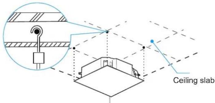
Sites with concrete slabs
Use embedded bolts and anchor bolts
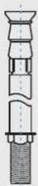
With steel frame
Directly set and use an angle iron for support.
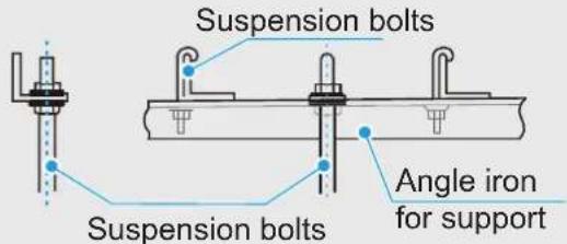
Indoor unit Installation

CAUTION
When installing the indoor unit, make the side of the electric control box obliquely enter the ceiling (as shown in the figure below) to avoid accidental damage to the ceiling by the electric control box during installation.
1 Existing ceiling (the ceiling surface needs to be level)
1
Cut a 590mm × 590mm square hole on the ceiling according to the shape of the mounting cardboard (see the figure below).
a. The center of the ceiling opening is the same as the center of the indoor unit of the air conditioner.
b. Determine the lengths and outlets of connecting pipe, drain pipe, and electrical wiring.
c. To keep the ceiling surface level and prevent vibration, strengthen the ceiling rigidity if necessary.
②
Using a pencil, mark the positions on the ceiling slab where the suspension bolts need to be fixed based on the distance between the four hanging holes on the indoor unit.
a. After drilling the holes, install 4 anchors bolts and fasten them, using turnbuckle nuts connecting or welding 4 suspension bolts ( 10mm) with fully threaded bolt to the 4 anchors bolts, and attach three nuts to the each suspension bolt, divide the nuts into two groups, with one nut on top as one group and two nuts at the bottom as another group, then install the indoor unit through the four lugs and nuts.
b. The diameter of the suspension bolt shall not be less than 10mm.
c. When the length of the hanger rod exceeds 1.5 meters, it is necessary to add two diagonal support rods to enhance stability. d. Because the ceilings and other architectural structures vary, it is necessary to discuss building details with the owner.
3
Use the hex nuts on the four mounting hooks to adjust evenly and make sure the indoor unit is level.
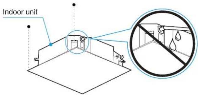
A
If the water discharge pipe is slanted, it may cause the water level switch to malfunction, and water may leak.
B
Adjust the position of the indoor unit to ensure that the interval of the four sides of the ceiling is even, and the bottom surface of the indoor unit should be recessed from the bottom surface of the ceiling by 10-12mm.
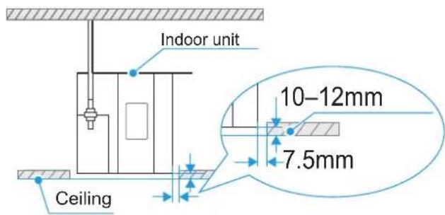

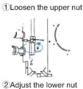
After adjusting the indoor unit position and level, tighten the nuts on the mounting hook to secure the air conditioner in place.
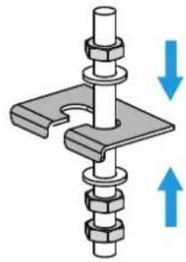
natural_image
Mechanical assembly diagram showing a clamping mechanism with two upward arrows indicating motion (no text or symbols)Tighten the upper and lower nuts

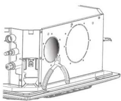
For units with fresh air functions, before installing indoor units: 1. Use diagonal pliers to remove the knockout at the fresh air unit at one side of the unit in advance. Install a fresh air flange at the fresh air unit and secure it with the flange connecting screws. 2. Use a knife to the fresh air blockage of the drain pan foam.
natural_image
Technical line drawing of a mechanical device with mounting brackets and internal components (no text or symbols)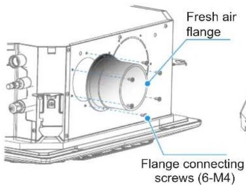
natural_image
Technical line drawing of a mechanical housing component (no text or symbols)
WARNING
When connecting the fresh air unit, insulate the fresh air pipe with polyethylene foam insulation materials that are at least 10mm thick.
The temperature difference between the fresh air provided by the fresh air unit to the indoor unit and the indoor temperature shall not exceed 5°C, otherwise there is a risk of condensation in the return air area of the air conditioner. Please use a fresh air unit equipped with a temperature regulation function. Or cover the enclosure of the fresh air outlet of the air conditioner with polyethylene foam insulation material with a thickness of at least 10mm. The area and thickness of the insulation material should be adjusted depending on the actual situation.

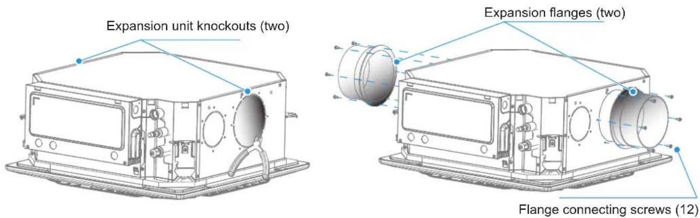
For models with expansion units, use diagonal pliers to remove the knockouts at the expansion units at two sides of the unit in advance before installing indoor units. Install expansion flanges at the expansion unit and secure them with the flange connecting screws.
2 New rooms and new ceilings

For the installation of lifting bolts, a hook can be embedded in the new room. Make sure the hook can withstand 4 times the weight of the indoor unit and will not loosen due to shrinkage of the concrete.

After the indoor unit is lifted, fix the mounting cardboard on the air conditioner unit with M5×20 screws (panel) to predetermine the size and position of the ceiling opening.
a. Make sure the ceiling is level when installing the ceiling.
b. Carry out installation as described above for the remaining parts (Point 1 of Existing Ceiling installation).

Carry out installation as described above (Point 3 of Existing Ceiling installation).

Remove the mounting cardboard.

NOTE
Make sure the indoor unit unit is level: Use a spirit level or a transparent rubber hose filled with water to correct the level of the indoor unit, otherwise water leakage may occur.
The indoor unit is equipped with a built-in drain pump and a water level switch. Do not tilt the unit in the opposite direction of the condensate water flow; otherwise, the water level switch will fail and cause water leakage.
Panel Installation

CAUTION
When installing the panel, avoid placing the display panel directly under the inlet/outlet pipelines.

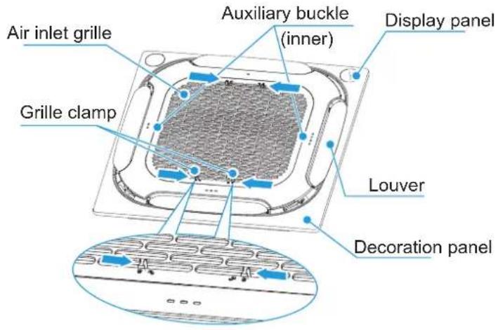
Remove the air inlet grille
Press the two grille clamps at the same time to lift the grille.
natural_image
Technical line drawing of a mechanical component with no visible text or symbols
NOTE
Do not position the panel so that it faces downwards or leans against the wall. Do not place it on a protruding object either.
Do not hit or squeeze the louver.

Install the panel

Install the panel on the indoor unit using bolts (M5×20) and washers.
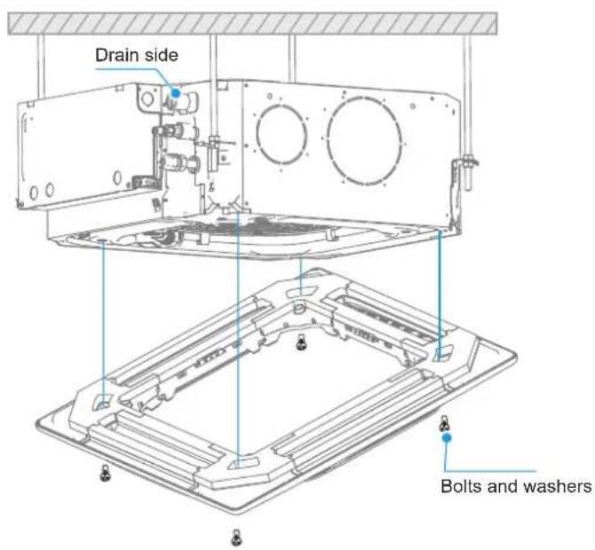
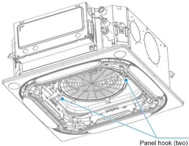

Tighten the screws under the panel hooks until the thickness of the sealing sponges 1 and 2 between the indoor unit and the panel outlet is reduced to about 4-6mm. The edge of the panel should be in good contact with the ceiling.
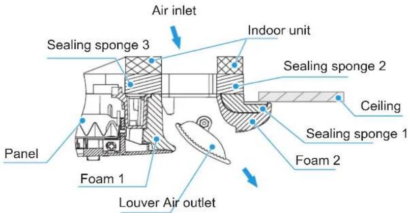

CAUTION
Improper screw tightening may cause the failure shown in the figure below.
After tightening the screws, if there is still a gap between the ceiling and the panel, the height of the indoor unit must be readjusted.
If the lift level of the indoor unit and the drain pipes are not affected, you can remove the panel and readjust the height of the indoor unit.
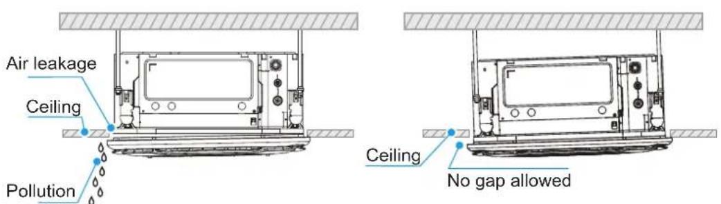
Droplets of condensed water, dripping water.
3
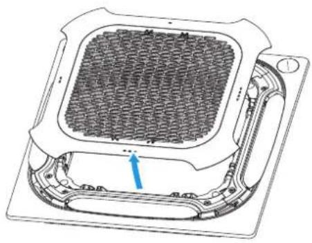
Install the air inlet grille
① Refer to the wiring nameplate located on the cover of the unit's electric control box, and connect the exposed wires of the panel to the corresponding interface of the unit's electric control.
② A safety hang rope is reserved for the suction grille. Please install the hanging rope into the hang rope slot.
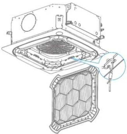
natural_image
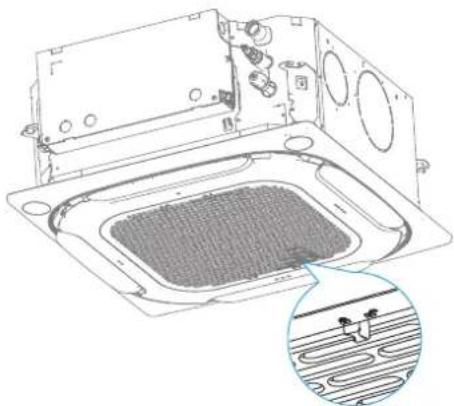
Technical diagram of a mechanical assembly with a fan and mesh structure, showing internal components (no text or symbols)③ Install the air inlet grille back into the corresponding position, and push it up slightly at the grille clamp position to ensure that the grille buckle is fully engaged in the slot of the panel, and the grille is in the closed position.
natural_image
Technical line drawing of a mechanical component with a grid-patterned base and internal components, plus an inset showing a textured surface (no text or symbols)5
Refrigerant Connecting Piping Installation
When connect different series of outdoor units, the length and level differences of piping connections. Refer to the Installation and Operation Manual of the outdoor unit.
!
CAUTION
The installation of pipe-work shall be kept to a minimum.
During the installation of the connecting pipes, do not allow air, dust, and other debris to penetrate the piping system, and make sure the interior of the pipes is dry.
Install the connecting pipes only when the indoor units and outdoor units are mounted.
When installing the connecting pipes, record the actual installation length of the liquid pipe so that additional refrigerant can be added.
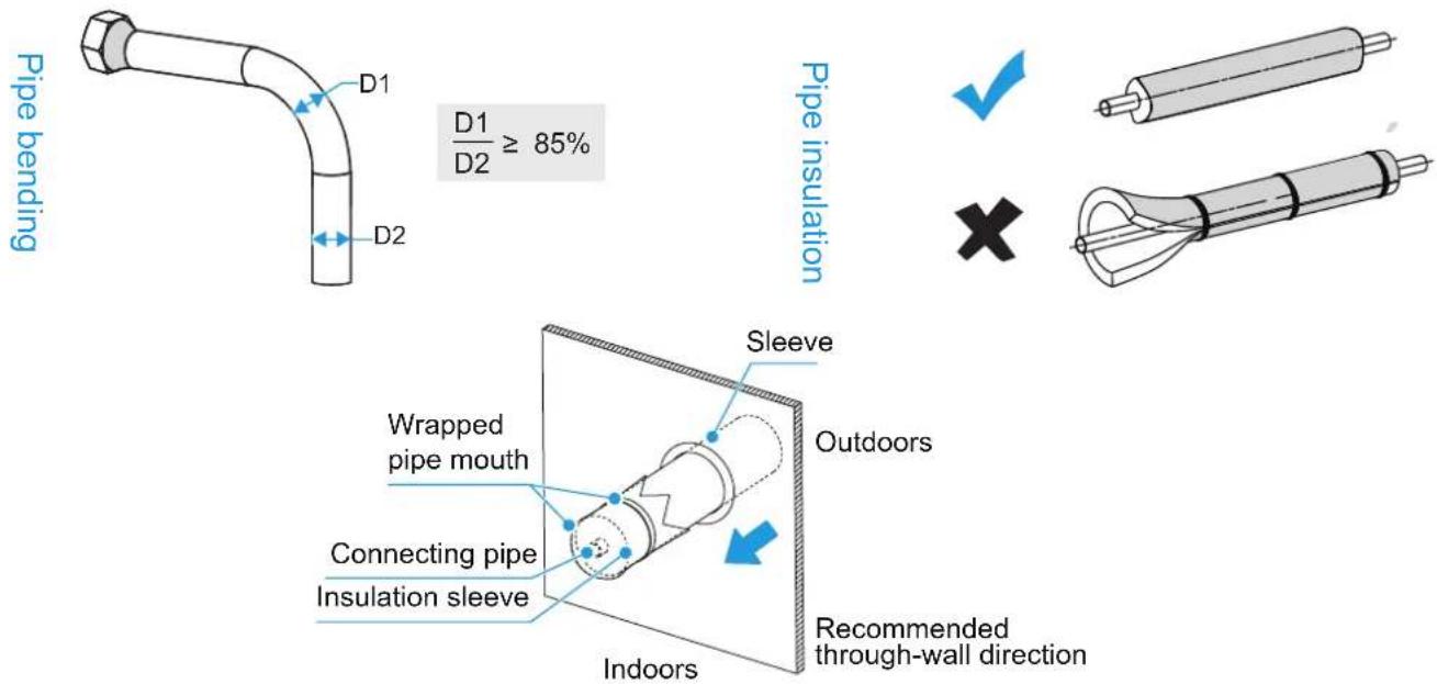
The connecting pipes must be wrapped with thermal insulation materials when they are installed.
In the event of refrigerant gas leakage during operation, please ventilate immediately.
Pipe Layout
① The deformed pipe area must not exceed 15%.
② A protective sleeve should be installed at the wall or floor hole.
③ The weld joint must not be inside the insulation.
④ The drill hole on the external wall must be sealed.
Pipe Connection Steps

CAUTION

Bend and arrange pipes carefully without damaging the pipes and their insulating layers.

Do not let the interface of the indoor unit bear the weight of the connecting pipe; otherwise, the connecting pipe may be crushed and deformed, which will affect the cooling (heating) effect, or the thermal insulation materials may be compressed, resulting in air leakage and condensation.
The connecting pipes to the outdoor units. Please refer the Installation and Operation Manual of the outdoor units.
Pipe Connection
Processing method
Mechanical bending processing: Wider application ( 6.35mm-28mm ), using spring pipe bender, manual pipe bender or electric pipe bender.

CAUTION
The bending angle should not exceed 90^ ; otherwise, wrinkles will be formed in the pipe, which can easily break.
The bending radius should not be smaller than 3.5D (pipe diameter) and should be as large as possible to prevent the pipe from becoming flattened or crushed.
When mechanically bending the pipe, the pipe bender inserted into the connecting pipe must be cleaned.
1
Brazing pipes
When brazing pipes, fill the pipes with nitrogen.

CAUTION
When it is necessary to fill the piping with nitrogen during brazing, the pressure must be kept at 0.02MPa using a pressure relief valve.
Do not use flux when brazing the piping. Use a phosphor copper that does not require flux.
Do not use any antioxidants when brazing the piping. The piping may become clogged with residual antioxidants, which may block components such as electronic expansion valves during operation.
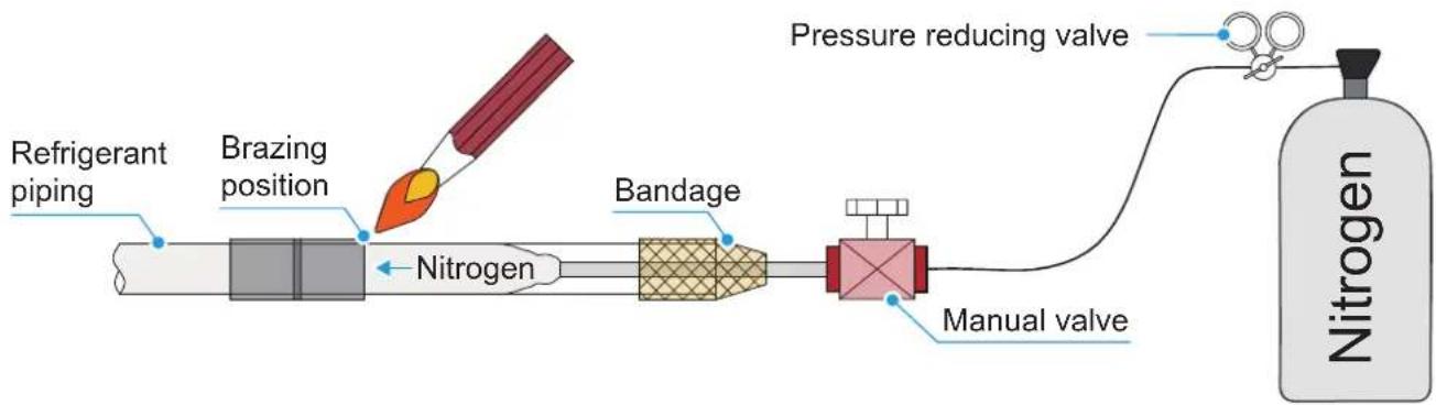
flowchart
graph LR
    A["Refrigerant piping"] --> B["Brazing position"]
    B --> C["Nitrogen"]
    C --> D["Bandage"]
    D --> E["Manual valve"]
    E --> F["Pressure reducing valve"]
    F --> G["Nitrogen"]
2
Flaring
To cut the piping with a pipe cutter, rotate the pipe cutter repeatedly.
Put the pipe into the connecting nut flaring, and both the gas pipe and liquid pipe of the indoor unit are connected by flaring.
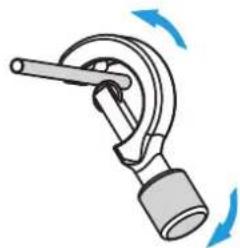
natural_image
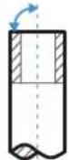
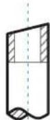
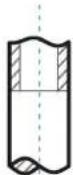
Diagram of a mechanical lever mechanism with blue directional arrows indicating rotation (no text or symbols)Pipe cutter

90^

Slope

Rough

Burrs
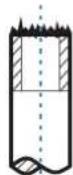
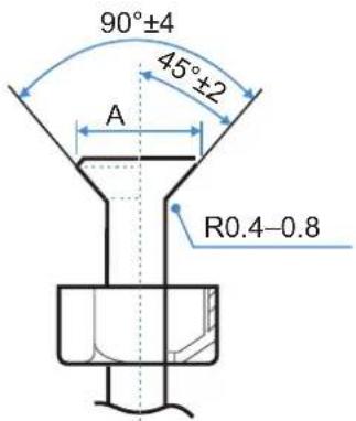
| Outer diameter (mm) | A (mm) | |
| Max. Min. | ||
| Φ6.35 | 8.7 | 8.3 |
| Φ9.52 | 12.4 | 12.0 |
| Φ12.7 | 15.8 | 15.4 |
| Φ15.9 | 19.1 18.6 | |
| Φ19.1 | 23.3 22.9 | |
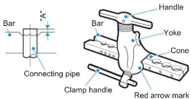

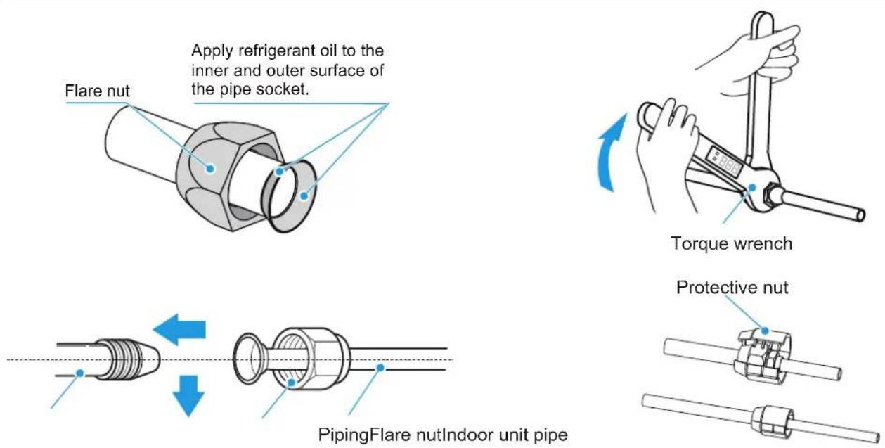
Nut fastening

Connect the indoor unit first, then connect the outdoor unit. Before tightening the flare nut, apply refrigeration oil on the inner and outer surface of the pipe flare (must use refrigeration oil compatible with the refrigerant for this model), and turn it 3 or 4 turns by hand to tighten it. When connecting or removing a pipe, use two wrenches at the same time.

Align the connecting piping, firstly tighten most of the thread of the connecting nut by hand, and then use a torque wrench to tighten the last 1-2 turns of the thread as shown in the figure.

The brazing is done on site, and the bell mouth cannot be used indoors.(For IEC/EN 60335-2-40 except IEC 60335-2-40: 2018)

The protective nut is a one-time part, it can not be reused. In case it is removed, it should be replaced with a new one.(For IEC 60335-2-40: 2018 only)

CAUTION
When flared joints are reused indoors, the flare part should be re-fabricated.
| Pipe size (mm) | Tightening torque [ N.m (kgf.cm)] |
| Φ6.35 | 14.2–17.2 (144–176) |
| Φ9.52 | 32.7–39.9 (333–407) |
| Φ12.7 | 49.5–60.3 (504–616) |
| Φ15.9 | 61.8–75.4 (630–770) |
| Φ19.1 | 97.2–118.6 (990–1210) |

CAUTION
Excessive torque will damage the flared mouth and nut, and too small torque cannot tighten the nut, which will cause refrigerant leakage. Please refer to the above table to determine the appropriate tightening torque.
Refrigerant Piping Fixing
Angle iron brackets or round steel hangers should be used for fixing. When the liquid pipe and gas pipe are suspended together, the size of the liquid pipe shall prevail.
| Pipe outer diameter (mm) | ≤20 | 20~40 | ≥40 |
| Horizontal pipe distance (m) | 1.0 | 1.5 | 2.0 |
| Stand pipe distance (m) | 1.5 | 2.0 | 2.5 |
Vacuum Pumping
Connect the vacuuming unit through a manifold to the service port of all stop valves.
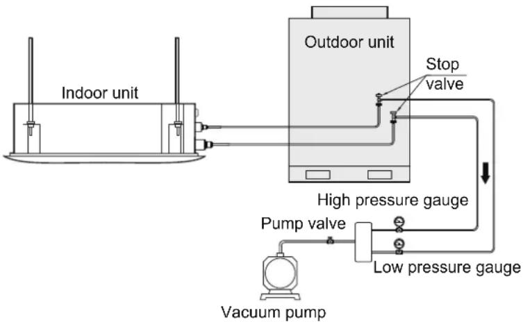
flowchart
graph TD
    A["Indoor unit"] --> B["Outdoor unit"]
    B --> C["Stop valve"]
    B --> D["High pressure gauge"]
    D --> E["Pump valve"]
    D --> F["Low pressure gauge"]
    E --> G["Vacuum pump"]
    F --> G

CAUTION
Do not purge the air with refrigerant of outdoor unit, it will cause fire or system malfunction.
Leak Detection
The leak test must satisfy the specifications of EN378-2.

To check for leaks: Vacuum leak test
① Evacuate the system from the liquid and gas piping to -100.7 kPa (-1.007 bar)(5 Torr absolute) for more than 2 hours.
② Once reached, turn off the vacuum pump and check that the pressure does not rise for at least 1 minute.
③ Should the pressure rise, the system may either contain moisture (see vacuum drying below) or have leaks.

To check for leaks: Pressure leak test
① Test for leaks by applying a bubble test solution to all piping connections.
② Discharge all nitrogen gas.
③ Break the vacuum by pressurising with nitrogen gas to a minimum gauge pressure of 0.2 MPa (2 bar). Never set the gauge pressure higher than the maximum operation pressure of the unit, i.e. 4.0 MPa (40 bar).

CAUTION
Under no circumstances shall potential sources of ignition be used in the searching for or detection of refrigerant leaks. A halide torch (or any other detector using a naked flame) shall not be used.
Leak detection fluids are suitable for use with most refrigerants but the use of detergents containing chlorine shall be avoided as the chlorine may react with the refrigerant and corrode the copper pipe-work.
Electronic leak detectors shall be used to detect flammable refrigerants, but the sensitivity may not be adequate, or may need re-calibration. (Detection equipment shall be calibrated in a refrigerant-free area.) Ensure that the detector is not a potential source of ignition and is suitable for the refrigerant used. Leak detection equipment shall be set at a percentage of the LFL of the refrigerant and shall be calibrated to the refrigerant employed and the appropriate percentage of gas (25 % maximum) is confirmed.

NOTE
ALWAYS use a recommended bubble test solution from your wholesaler.
NEVER use soap water:
Soap water may cause cracking of components, such as flare nuts or stop valve caps.
Soap water may contain salt, which absorbs moisture that will freeze when the piping gets cold.
Soap water contains ammonia which may lead to corrosion of flared joints (between the brass flare nut and the copper flare).
Refrigerant Charge
The refrigerant is pre-charged in the outdoor unit at the factory, but additional refrigerant may be necessary depending on the field piping.

WARNING
Compliance with national gas regulations shall be observed
keep ventilation openings clear of obstruction.
Ensure that the refrigeration system is earthed prior to charging the system with refrigerant.
Label the system when charging is complete (if not already).
Extreme care shall be taken not to overfill the refrigeration system.

CAUTION
Cylinders shall be kept upright if a siphon tube is present.
Insulation Treatment
Pipes on the liquid and air sides have a low temperature during cooling. Take sufficient insulation measures to prevent condensation.

- Be sure to use a thermal insulation material with a heat resistance of 120^ or higher for the gas pipe.
- The attached insulation material for the part of the indoor unit where the pipe connects must undergo heat insulation treatment that leaves no gaps.
- For outdoor pipelines, additional protective treatments should be performed, such as adding metal duct boxes or wrapping the pipes with aluminum foil materials. Thermal insulation materials directly exposed to the open air will degrade and lose their insulating properties.

CAUTION
Before installation of the drain pipe, determine its direction and elevation to avoid intersection with other pipelines to ensure that the slope is straight.
The highest point of the drain pipe should be equipped with a vent port to ensure the smooth drainage of condensate water, and the vent port must face downwards to prevent dirt from entering the pipe.
Do not connect the drain pipe to the wastewater pipe, sewage pipe, or other pipes that produce corrosive gases or odors. Otherwise, the indoor unit (especially the heat exchanger) may be corroded and odor may enter the room, negatively impacting the heat exchange effects and user experience. The user will assume responsibility for any consequences resulting from failure to abide by instructions.
After the pipeline connection is completed, a water test and a full water test should be done to check whether the drainage is smooth and whether the pipeline system leaks.
The air conditioner drain pipe must be installed separately from other sewage pipes, rainwater pipes and drain pipes in the building.
Adverse slope, convex and concave pipes are prohibited, as improper airflow will cause poor drainage.
Drain pipes need to be evenly wrapped with thermal insulation pipes to prevent condensation.
All joints of the drainage system must be sealed to prevent water leakage.
Please connect the drain pipes in the following ways. Improper installation of the pipes may result in water leakage and damage to furniture and property.
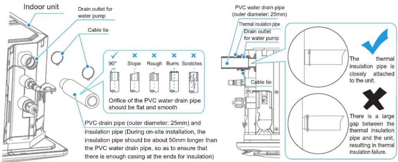
Installation Of Water Drain Pipe For The Indoor Unit
The drain pipe can be connected to the water pump outlet by using a PVC pipe, and fastening it with a cable tie. Then push the thermal insulation pipe to be closely attached to the indoor unit, and finally fasten the end with a cable tie.

The connection between the two ends of the drain pipes and the connection of the water pump outlet need to be fastened with a cable tie, in combination with PVC/rubber adhesives. Pay attention to the instructions for the use of the adhesives to prevent corrosion to the EPDM rubber. Use hard PVC adhesives for connecting to other water piping. Check that the connections are tight with no leakage.

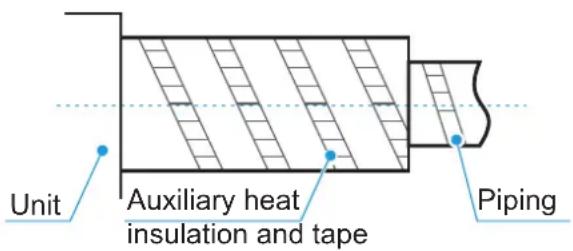
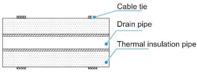
The water pump connecting pipe and drain pipe (in the indoor part) must be wrapped with heat insulation pipe evenly and bound with cable ties to prevent air from entering and producing condensate.

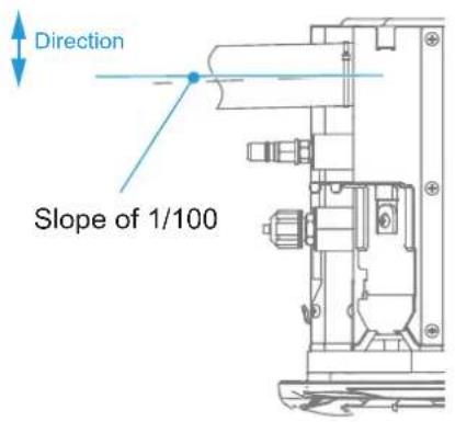
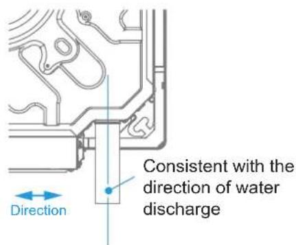
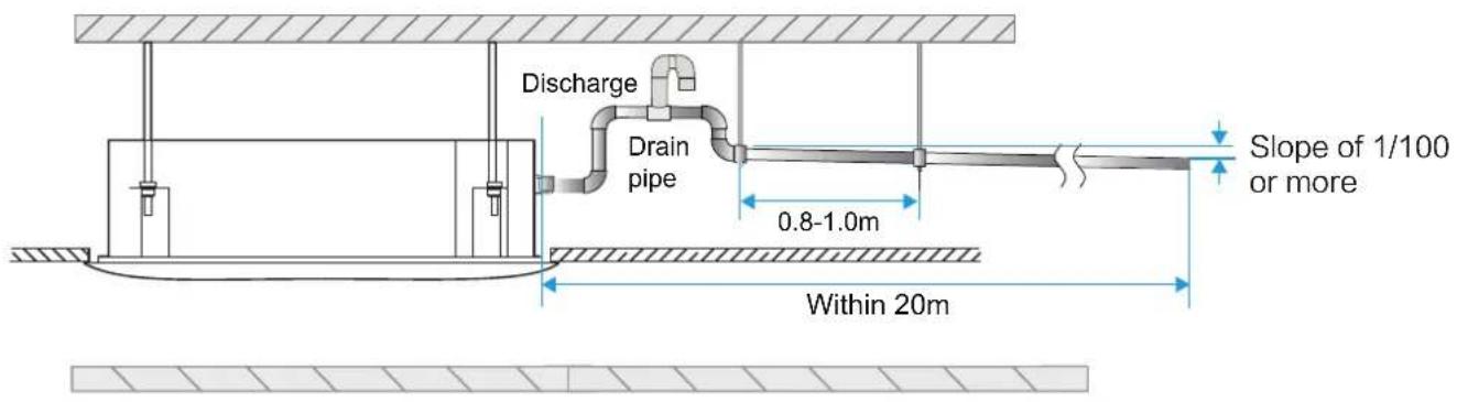
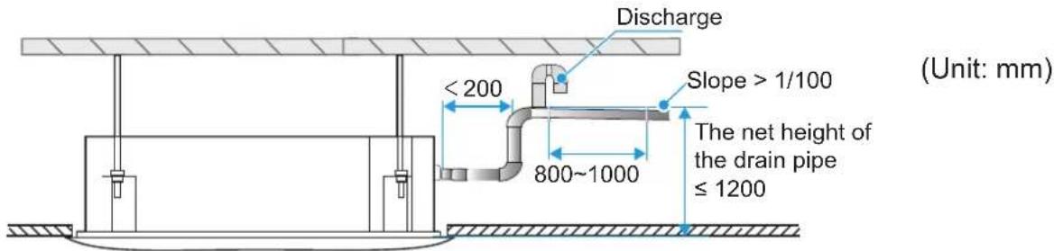
To prevent water from flowing back into the air conditioner when it stops running, the drain pipe should be inclined downward to the outdoor side (drainage side), with a downward slope of 1/100 or above. The drain pipe should be positioned in the same direction as the drainage outlet of the unit in the left and right direction, so that the drain pipe does not expand and collect water; otherwise, it may cause abnormal noise.

When connecting the drain pipe, do not pull the drain pipe forcefully, or it may become loose. The lateral length of the drain pipe should be within 20m, and a support point should be set every 0.8–1.0m to avoid air resistance caused by the deformation of the drain pipe. The drain pipe shall be equipped with a support point every 1.5-2.0m.
⑥
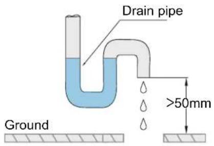
The end of the drain pipe must be more than 50mm above the ground or from the base of the water drainage slot. In addition, do not submerge it in water. To drain the condensed water directly into a ditch, the water drain pipe must bend upwards to form a U-shaped water plug to stop odors from entering the room via the water drain pipe.
- Connection method of the drain pipe:
Method to connect the drain pipe for a single unit
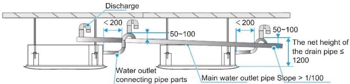
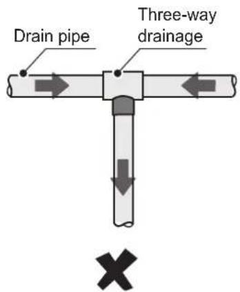
Drain pipes from multiple units are connected to the main drain pipe to be drained through the sewage pipe.
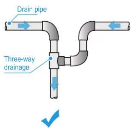
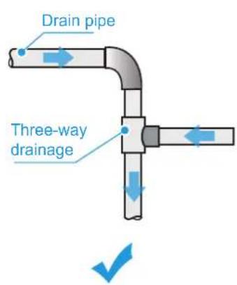
- Inconsistent drainage directions must be prevented for horizontal drain pipes to avoid adverse slopes and poor drainage.
Water Drainage Test

Before the test, make sure that the water discharge piping is smooth, and check that each connection is properly sealed.

Conduct the water drainage test in a new room before the ceiling is plastered.
- The drain pipe can be made of PVC pipe (outer diameter: 25mm). Based on the actual installation circumstances, users can purchase pipes of appropriate lengths from a sales agent or the local after-sales service center, or purchase them directly from the market.
- Connect the power supply, and set the air conditioner to operate in cooling mode. Check the operating sound of the drain pump, and check whether the drainage outlet is draining normally (depending on the length of the drain pipe, it may be delayed for about 1 minute before draining), and whether there is water leakage at each joint.
- If water drainage is carried out using the indoor unit drain pump, you need to remove the drain plug on the unit when conducting the water drainage test, to check whether the drain pump is operating. If the drain pump has not been started, check whether the drain pump has malfunctioned. Note: The drain pump only starts in cooling mode. While in heating mode, the drain pump remains turned off.
■ After the water drainage test is completed, turn off the power, remove the accumulated water, and replace the drain plug.
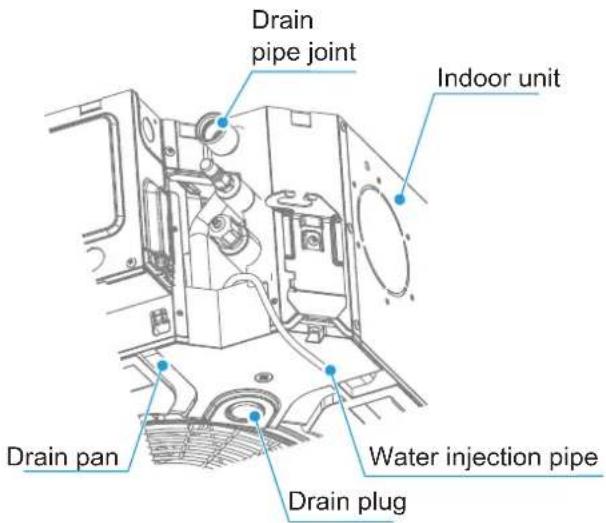

CAUTION
The drain plug at the bottom of the indoor unit is used to remove the accumulated water in the drain pan when the air conditioner is faulty and being repaired. The drain plug should be inserted during operation to prevent water leakage.
Faults, if any, need to be rectified as soon as possible.
7
Electrical Connection

DANGER
The power supply must be cut off before any electrical work is carried out. Do not conduct electrical work when the power is on; otherwise, it may cause serious personal injury.
The air conditioning unit must be earthed reliably and must meet the requirements of the local country/region. If the earthing is not reliable, serious personal injury due to electric leakage may occur.

WARNING
The appliance shall be installed in accordance with national wiring regulations.
Installation, inspection or maintenance operations must be completed by professional technicians. All parts and materials must comply with the relevant regulations of the local country/region.
The air conditioning unit must be equipped with a special power supply, and the power supply voltage should conform to the nominal working voltage range of the air conditioning unit.
The power supply of the air conditioning unit must be equipped with a power disconnect device that conforms to the requirements of relevant local technical standards for electrical equipment. The power disconnecting device must be equipped with short circuit protection, overload protection and electric leakage protection. The clearance between open contacts of the power disconnecting device shall be at least 3mm.
The core of the power supply cable must be made of copper, and the wire diameter should meet the current-carrying requirements. For details, refer to the "Power supply cable Diameter and Electric Leakage Protector Selection". A wire diameter that is too small may cause the power supply cable to heat up, resulting in a fire.
The power supply cable and the earth wires should be secured reliably to avoid stress on the terminals. Do not pull the power supply cable forcibly; otherwise, the wiring may become loosened or the terminal blocks may be damaged.
Strong current wires such as power supply cable cannot be connected to weak current wires such as communication wiring; otherwise, the product may be seriously damaged.
Do not bond and connect the power supply cable. Bonding and connecting the power supply cable may cause it to heat up, resulting in a fire.

CAUTION
Avoid bonding and connecting the communication wiring. If doing so is unavoidable, at the very least, ensure a reliable connection by crimping or soldering and make sure the copper wire at the connection is not exposed; otherwise, communication failure may occur.
The power supply cable and communication wiring must be routed separately, with a distance of over 5 cm. Otherwise, communication failure may occur.
Keep the vicinity of the air conditioning unit as clean as possible to avoid small animals from nesting and biting the cables. If a small animal touches or bites the cables, short circuiting or electric leakage may occur.
Do not connect the earth wires to the gas pipe, water pipe, lightning rod earth wires or telephone earth wires.
Gas pipe: Risk of explosion and fire when gas leaks.
Water pipe: If rigid plastic pipes are used, there will be no earthing effect.
Lightning rod earth wires or telephone earth wires: In the event of lightning strikes, abnormal earth potential may rise.
After all wiring is completed, check carefully before turning on the power supply.
Electrical Characteristics
| Capacity (kW) | Electric Specifications Of The Indoor Unit Indoor Fan Motor | ||||
| Frequency (Hz) | Voltage (V) | MCA (A) | MFA (A) | Rated Motor Output (W) | |
| 1.5 | 50/60 220~240 15 | 0.46 | 45 | ||
| 2.2 | 0.46 | 45 | |||
| 2.8 | 0.54 | 45 | |||
| 3.6 | 0.54 | 45 | |||
| 4.5 | 0.61 | 45 | |||
| 5.6 | 0.65 | 45 | |||
| 6.3 | 0.81 | 45 | |||
NOTES:
MCA: Min. Circuit Amps. (A), which is used to select the minimum circuit size to ensure safe operation over a long period of time.
MFA: Max. Fuse Amps. (A), which is used to select the circuit breaker.
Table of selection of power supply cable diameter
| 机型 | kW≤6.3 |
| Minimum sizing of the wiring (mm2) BVV Type, Copper core cable | 3×1.0 |
Schematic Figure Of The Main Terminal Blocks Of Main Control Board
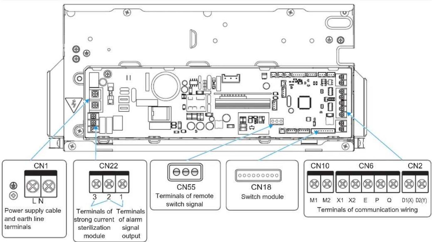

CAUTION


All weak point connection points meet SELV, such as X1, X2, P, Q, E, M1, M2, CN18, CN55 etc.
Wiring
1
Open the indoor unit's electric control box cover.
① Remove the two screws at the positions shown in the figure;
② Pull the bottom end of the electric control box cover horizontally outward;
③ Remove the electric control box cover by pulling downwards.
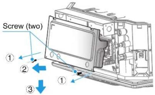
2
Connect the strong current wires (power supply cable, alarm signal output wires, and strong current sterilization wires) and weak current wires (communication wiring, remote switch connection wiring, expansion board connection wiring) to the electric control box through the strong and weak current inlets of electric control box.
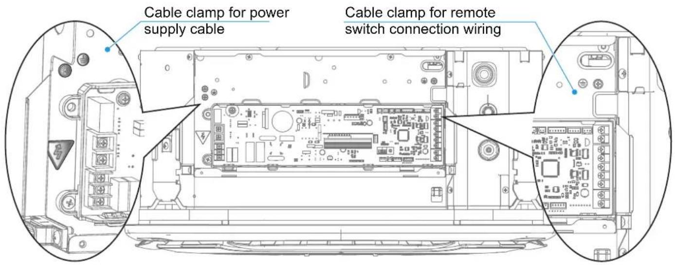

CAUTION
Power supply cable must be routed separately from the other cable such as communication wiring and display box communication wiring.
The strong and weak current wires must be separated.
The strong current sterilization module and expansion board are optional.

Power supply cable connection
① Connection between the power supply cable and power supply terminal
The power supply terminal of the indoor unit is fixed on the main control board, the power supply cable is connected to the power supply terminal labeled "CN1" on the main control board. The live and neutral wires are connected according to the main control board logos "L" and "N", and the earth wires is directly connected to the electric control box sheet metal part.
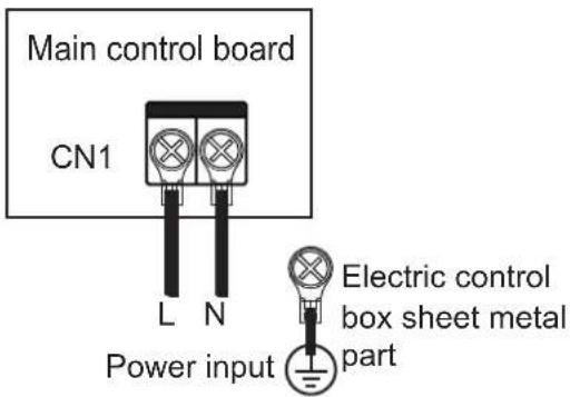

CAUTION

Do not bond and connect the power supply cable. Bonding and connecting the power supply cable may cause it to heat up, resulting in a fire.

The power supply cable must be crimped reliably using an insulated circular terminal block, and then connected to the power supply terminal of the indoor unit, as shown in the figure below.
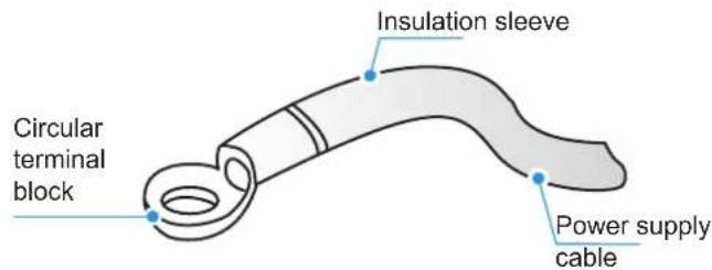

If it fails to crimp the insulated circular terminal block due to on-site limitations, connect the power supply cable of the same diameter to both sides of the power supply terminal block of the indoor unit, as shown in the figure below.
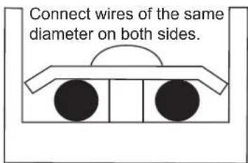

Do not press the power supply cable of the same wire diameter on the same side of the terminal. Do not use two power supply cable of different wire diameters for the same terminal blocks; otherwise, they can easily loosen due to uneven pressure and cause accidents, as shown in the figure below.
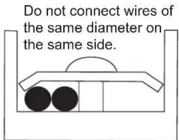
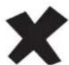

The connected power supply cable should be secured with a wire clamp to prevent loosening, as shown in the right figure.
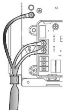
natural_image
Diagram of a cable connector with labeled terminals and connectors (no text or symbols present)② Power supply cable system connection
Power supply cable system connection depends on the methods of communication between the indoor unit and outdoor unit. For the HyperLink (M1M2) communication method, indoor units are allowed to have independent power supplies. For other communication methods, indoor units should be provided with uniform power supplies.
A Indoor units are provided with independent power supplies\*, which are wired as follows:
For HyperLink (M1M2) communication with independent power supply:
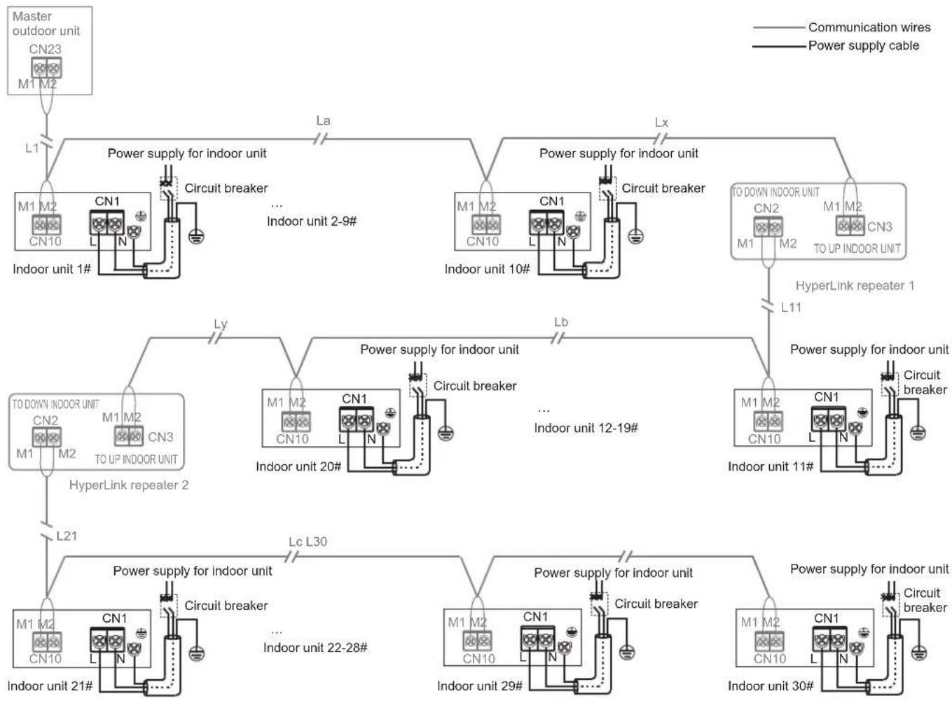
flowchart
graph TD
    A["Master outdoor unit\nCN23\nM1 M2"] --> B["L1"]
    B --> C["Power supply for indoor unit\nM1 M2\nCN10\nL N"]
    C --> D["Circuit breaker"]
    D --> E["... Indoor unit 2-9#"]
    E --> F["La"]
    F --> G["Power supply for indoor unit\nM1 M2\nCN10\nL N"]
    G --> H["Circuit breaker"]
    H --> I["Lx"]
    I --> J["TO DOWN indoor unit\nCN2\nM1 M2\nTO UP indoor unit\nL11"]
    J --> K["HyperLink repeater 1"]
    K --> L["Ly"]
    L --> M["Power supply for indoor unit\nTO DOWN indoor unit\nCN2\nM1 M2\nTO UP indoor unit\nL21"]
    M --> N["Circuit breaker"]
    N --> O["... Indoor unit 12-19#"]
    O --> P["Lb"]
    P --> Q["Power supply for indoor unit\nM1 M2\nCN10\nL N"]
    Q --> R["Circuit breaker"]
    R --> S["... Indoor unit 12-19#"]
    S --> T["Lc L30"]
    T --> U["Power supply for indoor unit\nM1 M2\nCN10\nL N"]
    U --> V["Circuit breaker"]
    V --> W["... Indoor unit 22-28#"]
    W --> X["Lc L30"]
    X --> Y["Power supply for indoor unit\nM1 M2\nCN10\nL N"]
    Y --> Z["Circuit breaker"]
    Z --> AA["... Indoor unit 22-28#"]
    AA --> AB["Lc L30"]
    AB --> AC["Power supply for indoor unit\nM1 M2\nCN10\nL N"]
    AC --> AD["Circuit breaker"]
    AD --> AE["... Indoor unit 22-28#"]
    AE --> AF["Lc L30"]
CAUTION
When the indoor units are provided with independent power supplies, the indoor units in the same refrigerant system should be V8 indoor units*, and the communication between indoor units and outdoor unit adopts a HyperLink (M1M2) with an independent power supply.
This connection method has the function of an independent power supply, so in the same refrigerant system, the number of indoor units must not exceed 30 sets, and a maximum of only two repeaters may be installed*.
One repeater shall be added for every 10 indoor units or a communication wire length of 200m added.
B Indoor units are provided with unified power supply\*, which are wired as follows:
1. HyperLink (M1M2) communication with the unified power supply:
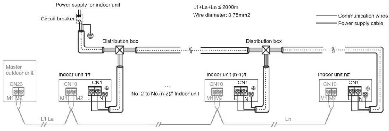
flowchart
graph LR
    A["Power supply for indoor unit"] --> B["Circuit breaker"]
    B --> C["Distribution box"]
    C --> D["..."]
    D --> E["Distribution box"]
    E --> F["..."]
    F --> G["Indoor unit n#"]
    G --> H["Indoor unit (n-1)#"]
    H --> I["..."]
    I --> J["Indoor unit 1#"]
    J --> K["L1 La"]
    K --> L["Master outdoor unit CN23 M1 M2"]
    style A fill:#f9f,stroke:#333
    style B fill:#ccf,stroke:#333
    style C fill:#cfc,stroke:#333
    style D fill:#fcc,stroke:#333
    style E fill:#cff,stroke:#333
    style F fill:#ffc,stroke:#333
    style G fill:#cfc,stroke:#333
    style H fill:#cfc,stroke:#333
    style I fill:#cfc,stroke:#333
    style J fill:#cfc,stroke:#333
    style K fill:#fff,stroke:#333
    style L fill:#fff,stroke:#333
    style_M["L1+La+Ln ≤ 2000m Wire diameter: 0.75mm2"] -.-> N["Communication wires"]
    style_O["Power supply cable"] -.-> P["No. 2 to No.(n-2)# Indoor unit"]
2. P/Q communication:
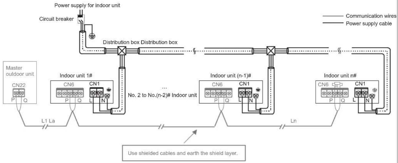
flowchart
graph TD
    A["Power supply for indoor unit"] --> B["Circuit breaker"]
    B --> C["Distribution box Distribution box"]
    C --> D["Master outdoor unit CN22 P Q"]
    C --> E["Indoor unit 1# CN6 P Q CN1 L N"]
    C --> F["..."]
    C --> G["Indoor unit (n-1)# CN6 P Q CN1 L N"]
    C --> H["Indoor unit n# CN6 P Q CN1 L N"]
    I["Use shielded cables and earth the shield layer."] --> J["L1 La"]
    J --> K["Ln"]
    style A fill:#f9f,stroke:#333
    style B fill:#ccf,stroke:#333
    style C fill:#cfc,stroke:#333
    style D fill:#fcc,stroke:#333
    style E fill:#cff,stroke:#333
    style F fill:#ffc,stroke:#333
    style G fill:#cfc,stroke:#333
    style H fill:#fcc,stroke:#333
3. P/Q/E communication:
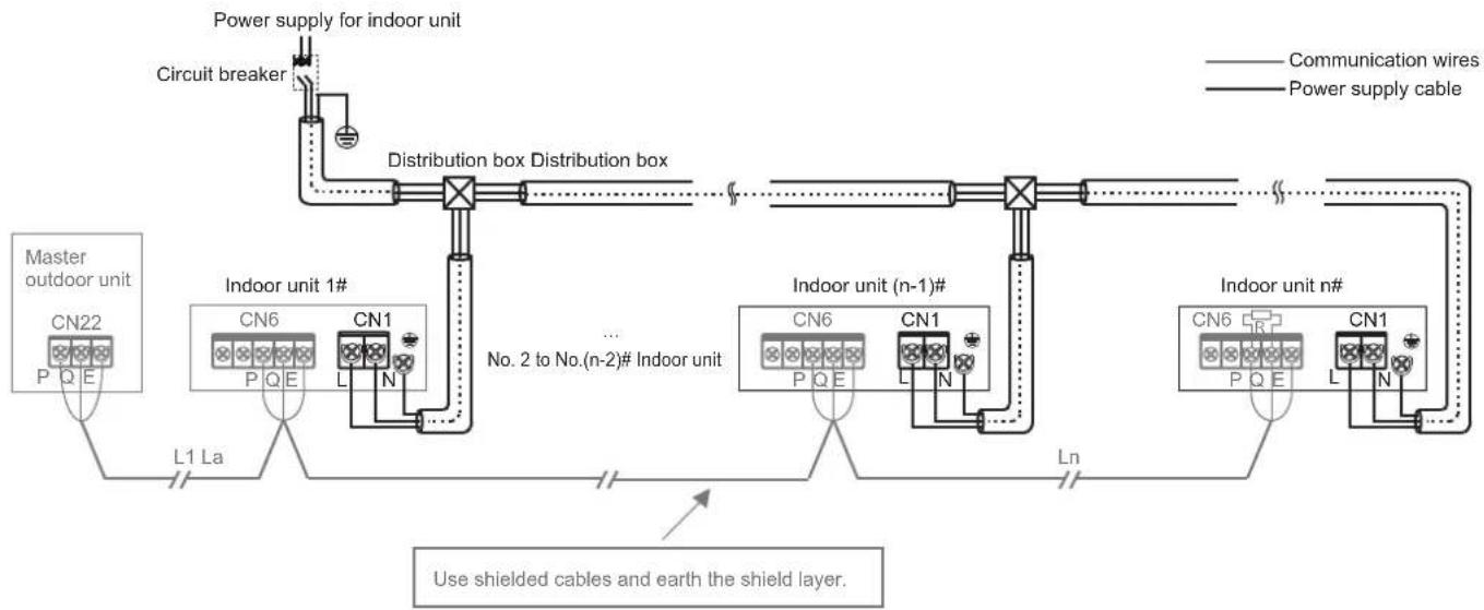
flowchart
graph LR
    A["Power supply for indoor unit"] --> B["Circuit breaker"]
    B --> C["Distribution box Distribution box"]
    C --> D["Master outdoor unit CN22 P Q E"]
    C --> E["Indoor unit 1# CN6 P Q E CN1 L N"]
    C --> F["..."]
    C --> G["Indoor unit (n-1)# CN6 P Q E CN1 L N"]
    C --> H["Indoor unit n# CN6 P Q E CN1 L N"]
    C --> I["L1 La"]
    I --> J["Use shielded cables and earth the shield layer."]
    style A fill:#f9f,stroke:#333
    style B fill:#ccf,stroke:#333
    style C fill:#cfc,stroke:#333
    style D fill:#fcc,stroke:#333
    style E fill:#cff,stroke:#333
    style F fill:#ffc,stroke:#333
    style G fill:#cfc,stroke:#333
    style H fill:#fcc,stroke:#333
    style I fill:#cfc,stroke:#333

CAUTION
When the indoor units are provided with a unified power supply, if the indoor units in the same refrigerant system are V8 indoor units, then indoor units and outdoor unit can communicate either via HyperLink (M1M2) with a unified power supply, or via P/Q. If some of the indoor units in the same refrigerant system are non-V8 series, then indoor units and outdoor unit can only communicate via P/Q/E communication.
Both P/Q communication and HyperLink (M1M2) communication are indoor and outdoor communication, and only one of them can be selected. Do not connect P/Q communication and HyperLink (M1M2) communication at the same time in the same system. Do not connect HyperLink (M1M2) communication to D1D2 communication.

NOTE
V8 indoor units *: with V8 printed on the packaging carton
Independent power supply*: With separate circuit breakers, the power supply for each indoor unit can be controlled independently.
Unified power supply*: All the indoor units in the system are controlled by one circuit breaker.
Repeater*: power supply repeater, which is used to compensate for the voltage drop due to excessive length of line or line resistance when the main control board of outdoor unit provides independent power supply for indoor units through the HyperLink (M1M2) communication wiring. It is only used in refrigerant systems where indoor units are provided with an independent power supply.

Wiring figure of main power supply
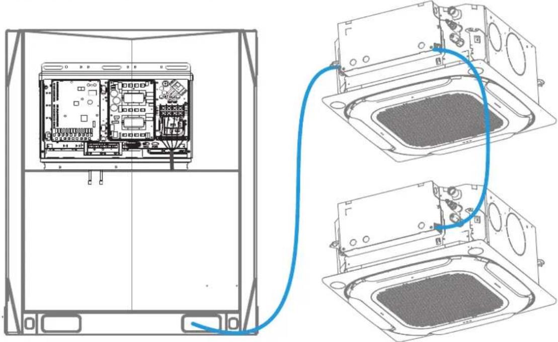
natural_image
Technical line drawing of an electronic device showing internal components connected to a rack-mounted unit (no text or symbols present)
WARNING
The main power supply wiring needs to be added with protective wire conduit.
① Selection of communication method for indoor units
Equipped with independently developed HyperLink (M1M2) communication, V8 series indoor units also preserve the previous RS-485 (PQE) communication method. They are compatible with non-V8 indoor units. Pay attention to the type of indoor unit before connecting communication wiring. Please refer to the following table to select an appropriate communication method.
| Indoor unit type | Optional communication method between indoor units and outdoor unit | Remarks |
| Are all the indoor units in the system V8 series | HyperLink (M1M2) communication | 1. Independent power supply for indoor units*.2. Any topology connection of communication wiring.3. Two-core and non-polar communication for M1M2. |
| RS-485 (PQ) communication | 1. The indoor units need to be powered uniformly.2. The communication cables must be connected in serial.3. Two-core and non-polar communication for PQ. | |
| Are some of the indoor units in the system non-V8 series | RS-485 (PQE) communication | 1. The indoor units need to be powered uniformly.2. The communication cables must be connected in serial.3. PQE cables must be 3-core and PQ non-polar. |
② Table of selection of communication wiring diameter
| Function | Indoor unit and outdoor unit communication | One controller to one indoor unit (Two controllers to one indoor unit) Communication | One-to-more (centralized controller) Communication | |||
| Item | HyperLink (M1M2) communication (Indoor units are powered separately) | HyperLink (M1M2) communication (Indoor units are powered uniformly) | P/Q communication (Indoor units are powered uniformly) | P/Q/E communication (Indoor units are powered uniformly) | X1X2 communication | D1D2 communication |
| Wire diameter | 2 × 1.5mm^2 Wire resistance ≤ 1.33Ω/100m | 2 × 0.75mm^2 | 2 × 0.75mm^2 (shielded cable) | 3 × 0.75mm^2 (shielded cable) | 2 × 0.75mm^2 (shielded cable) | 2 × 0.75mm^2 (shielded cable) |
| Length | ≤ 600m (add two repeaters) | ≤ 200m≤ 1200m≤ 1200m≤ 2000 | ||||
Please select the communication wiring according to the requirements in the above reference table. Use shielded cables for communication when strong magnetism or interference is present.
On-site wiring must comply with the relevant regulations of the local country/region and must be completed by professionals.
Do not connect the communication wiring when the power is on.
Do not connect the power supply cable to the communication terminal; otherwise, the main control board may be damaged.
The standard value of the screw torque of the communication wiring terminal is 0.5N·m. Insufficient torque may cause poor contact; excessive torque may damage the screws and power supply terminals.
Both HyperLink (M1M2) communication and PQ communication are internal and external, so only one of the two can be selected. Do not connect both HyperLink (M1M2) communication wiring and PQ communication wiring to the same system, otherwise the indoor unit and outdoor unit cannot communicate normally.
If some of the indoor units in the same refrigerant system are non-V8 series, only P/Q/E communication can be selected for the indoor unit and outdoor unit communication. The three-core shielded cable of 3×0.75mm2 is required to connect "P", "Q", and "E".
Do not bundle the communication wiring with the refrigerant pipeline, power supply cable, etc. When the power supply cable and the communication wiring are laid in parallel, a distance of more than 5cm should be maintained to prevent interference from the signal source.
When the construction personnel of the indoor unit and outdoor unit are working separately, information communication and synchronization are required. Do not connect the outdoor unit to HyperLink (M1M2) and the indoor unit to PQ. Do not connect the outdoor unit to PQ and the indoor unit to HyperLink (M1M2).
Bonding and connecting the communication wiring should be avoided, but if it is used, at the very least, ensure a reliable connection by crimping or soldering and make sure the copper wire at the connection is not exposed; otherwise, communication failure may occur.

HyperLink (M1M2) communication (with independent power supply)
Single unit: HyperLink (M1M2) communication is a new type of indoor unit and outdoor unit communication technology. When the indoor units are provided with independent power supplies, use 2×1.5mm2 communication cables. M1 and M2 ports are located at terminal block "CN10" of the main control board. There is no distinction between negative and positive electrodes. For details, see the following figure:
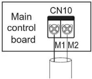
Connect to outdoor unit M1M2 (HyperLink)

CAUTION
Do not connect the HyperLink (M1M2) communication wiring to the PQ or D1D2 communication wiring.
System: The HyperLink (M1M2) communication wiring with an independent power supply between indoor unit and outdoor unit can reach a length of up to 600 meters, supporting any topology connection. The following figure shows a serial connection:
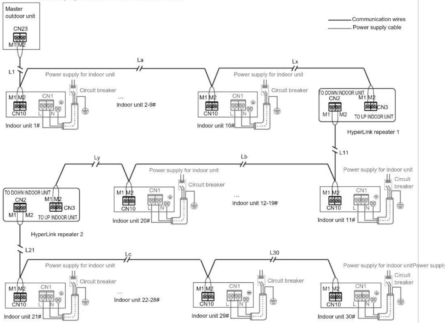
flowchart
graph TD
    A["Master outdoor unit"] --> B["L1"]
    B --> C["M1 M2 CN23 M1 M2"]
    C --> D["Power supply for indoor unit"]
    D --> E["La"]
    E --> F["M1 M2 CN10 L N"]
    F --> G["Circuit breaker ... Indoor unit 2-9#"]
    G --> H["Lx"]
    H --> I["M1 M2 CN10 L N"]
    I --> J["Circuit breaker"]
    J --> K["T0 DOWN INDOOR UNIT CN2 M1 M2 TO UP INDOOR UNIT"]
    K --> L["HyperLink repeater 1"]
    L --> M["L11"]
    M --> N["M1 M2 CN10 L N"]
    N --> O["Circuit breaker ... Indoor unit 12-19#"]
    O --> P["Lb"]
    P --> Q["Power supply for indoor unit"]
    Q --> R["Ly"]
    R --> S["M1 M2 CN3 TO UP INDOOR UNIT"]
    S --> T["Power supply for indoor unit"]
    T --> U["L21"]
    U --> V["Power supply for indoor unit"]
    V --> W["Lc"]
    W --> X["Power supply for indoor unit"]
    X --> Y["L30"]
    Y --> Z["M1 M2 CN10 L N"]
    Z --> AA["Circuit breaker ... Indoor unit 22-28#"]
    AA --> AB["L30"]
    AB --> AC["Power supply for indoor unit"]
    AC --> AD["L21"]
    AD --> AE["Power supply for indoor unit"]
    AE --> AF["L30"]
L1+La+Lx ≤ 200m L11+Lb+Ly ≤ 200m L21+Lc+L30 ≤ 200m
For other connection methods (tree topology, star topology, ring topology), please refer to the technical manual or consult technical personnel.

CAUTION
If the total length is less than or equal to 200m and the total number of indoor units is less than or equals to 10 sets, the electronic expansion valve in indoor unit can be powered and controlled by the master outdoor unit.
If the total length is longer than 200m or the total number of indoor units is more than 10 sets, a repeater is required to increase the bus voltage.
The limit of one repeater is 200m cable length or maximum 10 indoor units.
A maximum of two repeaters can be installed in the same refrigerant system.
HyperLink (M1M2) communication can control the electronic expansion valve in indoor unit independently, this function requires the maximum number of indoor units in the same refrigerant system must be less than or equal to 30 sets.
The repeaters and the outdoor units must connect to an unified power supply system, or the repeater uses an uninterruptible power supply.
Refer to the Installation and Operation Manual of repeater for detail.
For one repeater application, communication cable among the master outdoor unit, indoor units and repeater must use the CN3 port in repeater, the communication cable among repeater and the rest indoor units must use the CN2 port in repeater.
For two repeaters application, the communication cable among the master outdoor unit, indoor units and repeater 1 must use the CN3 port in repeater1, the communication cable among repeater 1, indoor units and repeater 2 must use the CN2 port in repeater 1 and CN3 port in repeater 2.
The electronic expansion valve in indoor unit can be powered and controlled by the master outdoor unit. If a separate power supply applied for indoor units.
The repeater is optional, contact dealer for detail.

HyperLink (M1M2) communication (with unified power supply)
Single unit: When the indoor units are provided with unified power supply, it is not necessary for HyperLink (M1M2) communication wiring to provide an independent power supply for indoor units. In this case, use 2 × 0.75mm^2 communication cables. M1 and M2 ports are located at terminal block "CN10" of the main control board. There is no distinction between negative and positive electrodes. For details, see the following figure:
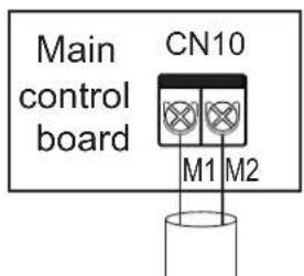
Connect to outdoor unit M1M2 (HyperLink)

CAUTION

Do not connect the HyperLink (M1M2) communication wiring to the PQ or D1D2 communication wiring.
System: The HyperLink (M1M2) communication wiring with a unified power supply between indoor unit and outdoor unit can reach a length of up to 2000 meters, supporting any topology connection. The following figure shows a serial connection:
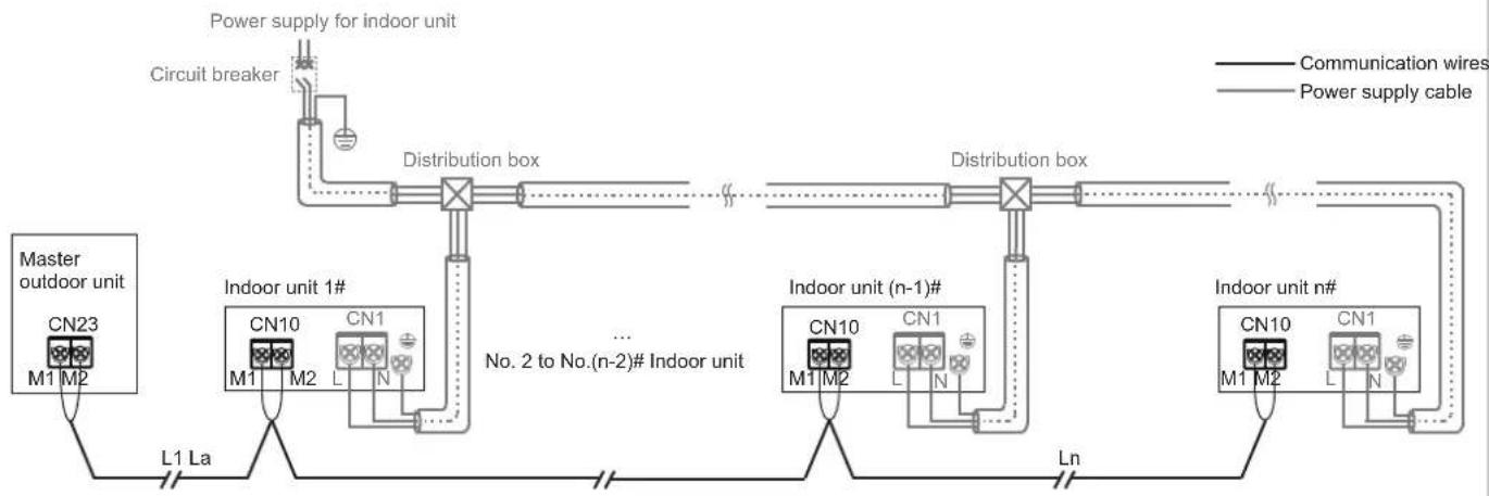
flowchart
graph LR
    A["Circuit breaker"] --> B["Distribution box"]
    B --> C["Distribution box"]
    D["Power supply for indoor unit"] --> B
    E["Master outdoor unit"] --> F["L1 La"]
    F --> G["Indoor unit 1#"]
    G --> H["No. 2 to No.(n-2)# Indoor unit"]
    H --> I["Indoor unit (n-1)#"]
    I --> J["Ln"]
    J --> K["Indoor unit n#"]
    L["Communication wires"] --> M["CN10"]
    N["Power supply cable"] --> O["CN10"]
    P["No. 2 to No.(n-2)# Indoor unit"] --> Q["CN10"]
    R["Indoor unit n#"] --> S["CN10"]
    T["Power supply cable"] --> U["CN10"]
L1+La+Ln ≤ 2000m
For other connection methods (tree topology, star topology, ring topology), please refer to the technical manual or consult technical personnel.

CAUTION
When HyperLink (M1M2) with a unified power supply is available, a unified power supply for indoor units is required. For details, see "Power supply cable Connection".
When HyperLink (M1M2) with a unified power supply is available, there is no need to connect a repeater to the system.

P/Q communication
Single unit: Use a shielded cable for the P/Q communication and properly earth the shield layer. P and Q ports are located at terminal block "CN6" of the main control board. There is no distinction between negative and positive electrodes. Connect the shield layer to the sheet metal of the electric control box, as shown in the following figure:
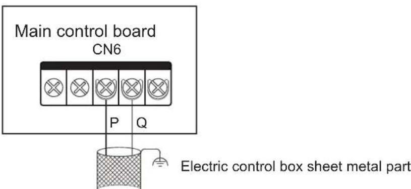
Connect to the outdoor unit PQ
System: The maximum total length of the P/Q communication cable of the Indoor unit and outdoor unit can be up to 1200m, and can be connected in serial, as shown in the figure below:
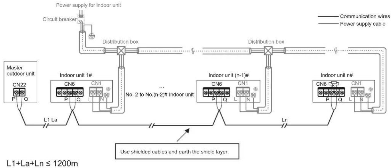
flowchart
graph LR
    A["Power supply for indoor unit"] --> B["Circuit breaker"]
    B --> C["Distribution box"]
    C --> D["Distribution box"]
    D --> E["Indoor unit 1#"]
    E --> F["No. 2 to No.(n-2)# Indoor unit"]
    F --> G["Indoor unit (n-1)#"]
    G --> H["L1 La"]
    H --> I["Master outdoor unit CN22 P Q"]
    G --> J["Indoor unit n#"]
    J --> K["Ln"]
    K --> L["Use shielded cables and earth the shield layer."]
    style A fill:#f9f,stroke:#333
    style B fill:#ccf,stroke:#333
    style C fill:#cfc,stroke:#333
    style D fill:#fcc,stroke:#333
    style E fill:#cff,stroke:#333
    style F fill:#ffc,stroke:#333
    style G fill:#cfc,stroke:#333
    style H fill:#fcc,stroke:#333
    style I fill:#fff,stroke:#333
    style J fill:#cfc,stroke:#333
    style K fill:#fcc,stroke:#333
    style L fill:#fff,stroke:#333
D P/Q/E communication
If some of the indoor units in the same refrigerant system are non-V8 series, it is required to connect "P", "Q", and "E" for P/Q/E communication.
Single unit: Use a shielded cable for the P/Q/E communication and properly earth the shield layer. P, Q, and E ports are located at terminal block "CN6" of the main control board. There is no distinction between negative and positive electrodes. Connect the shield layer to the sheet metal of the electric control box, as shown in the following figure:
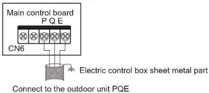
System: The maximum total length of the P/Q/E communication cable of the indoor unit and outdoor unit can be up to 1200m, and can be connected in serial, as shown in the figure below:
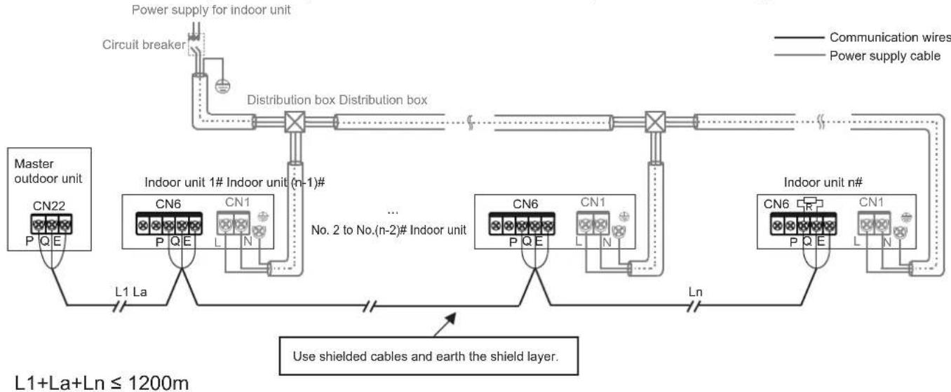
flowchart
graph TD
    A["Power supply for indoor unit"] --> B["Circuit breaker"]
    B --> C["Distribution box Distribution box"]
    C --> D["Master outdoor unit CN22 P Q E"]
    C --> E["Indoor unit 1# Indoor unit (n-1)#"]
    C --> F["..."]
    C --> G["No. 2 to No.(n-2)# Indoor unit"]
    C --> H["L1 La"]
    H --> I["Use shielded cables and earth the shield layer."]
    I --> J["CN6 P Q E CN1 L N"]
    I --> K["Ln"]
    K --> L["Indoor unit n# CN6 P Q E CN1 L N"]
    L --> M["End"]

CAUTION
When P/Q or P/Q/E communication is used, the indoor units need to be powered uniformly.
Either P/Q, P/Q/E communication or HyperLink (M1M2) communication can be selected. If it is required for indoor units to have independent power supplies, then HyperLink (M1M2) communication must be selected.
Use only shielded cables for P/Q or P/Q/E communication. Otherwise, the indoor unit and outdoor unit communication may be affected.
A matching resistor needs to be added to the last indoor unit on the PQ (in the accessory bag of the outdoor unit).
④ X1/X2 communication cable connection
The X1X2 communication wiring is mainly connected to the wired controller to achieve one controller per indoor unit and two controllers per indoor unit. The total length of the X1X2 communication wiring can reach 200 meters. Please use shielded wires, but the shield layer cannot be earthed. X1 and X2 ports are located at terminal block "CN6" of the main control board. There is no distinction between negative and positive electrodes. For details, see the following figure:
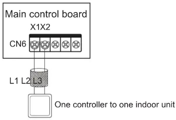
flowchart
graph TD
    A["Main control board X1X2"] --> B["L1 L2 L3"]
    B --> C["One controller to one indoor unit"]
L1 ≤ 200m, L2 + L3 ≤ 200m.
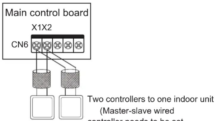
Two controllers to one indoor unit (Master-slave wired controller needs to be set. For details, see the wired controller manual.)

CAUTION
Two wired controllers of the same model can be used to control one indoor unit at the same time. In this case, need to set one controller to be the master and the other to be the slave. For details, see the wired controller manual.

Achieving one-to-multiple and two-to-multiple functions of the indoor unit wired controller through D1D2 communication (a maximum of 16 sets)
D1D2 communication is 485 communication. The one-to-more and two-to-more functions of the indoor unit wired controller can be achieved through D1D2 communication, as shown in the figure below:
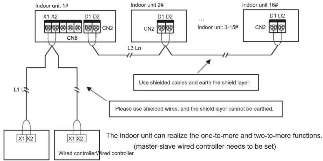
flowchart
graph TD
    A["Indoor unit 1#"] --> B["X1 X2"]
    A --> C["D1 D2"]
    A --> D["CN2"]
    B --> E["L1 L"]
    C --> F["L3 Ln"]
    D --> F
    G["Indoor unit 2#"] --> H["CN2"]
    I["... Indoor unit 3-15#"] --> J["D1 D2"]
    K["Indoor unit 16#"] --> L["CN2"]
    M["Use shielded cables and earth the shield layer."] --> N["L1 L"]
    O["Please use shielded wires, and the shield layer cannot be earthed."] --> P["Wired controller"]
    Q["The indoor unit can realize the one-to-more and two-to-more functions. (master-slave wired controller needs to be set)"] --> R["Wired controller"]
L1+L2 ≤ 200m, L3+Ln ≤ 1200m

CAUTION
When the indoor units in the same refrigerant system are V8 indoor units, D1D2 communication can enable one-to-multiple and two-to-multiple functions of the indoor unit wired controller.
To enable two-to-multiple functions, wired controllers must be of the same model.

Achieving centralized control of the indoor unit through D1D2 communication
The D1D2 communication wiring can also be connected to the centralized controller to achieve centralized control of the indoor unit, as shown in the figure below:
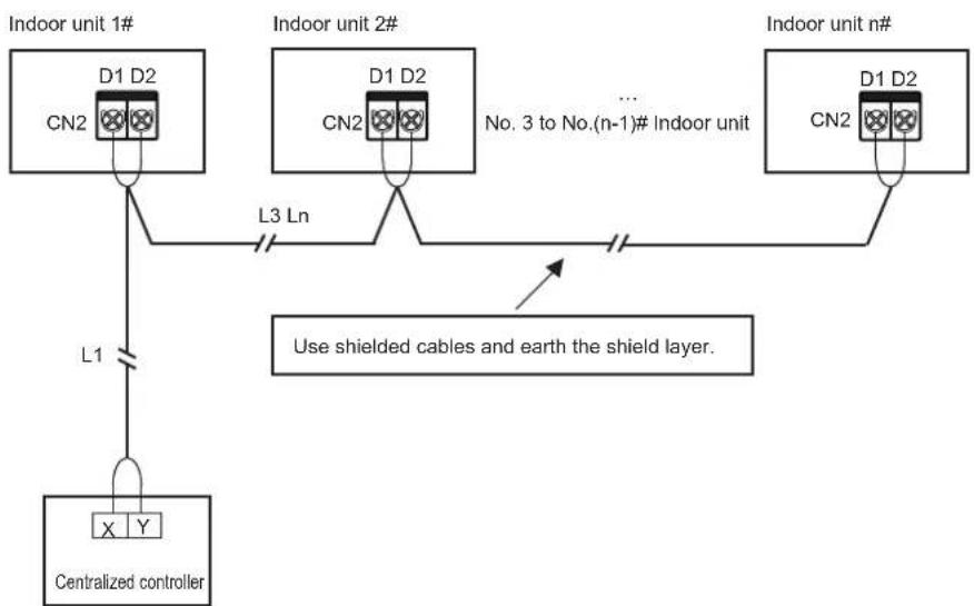
flowchart
graph TD
    A["Centralized controller"] -->|L1| B["Indoor unit 1#"]
    B --> C["D1 D2 CN2"]
    B --> D["D1 D2 CN2"]
    B --> E["L3 Ln"]
    C --> F["Indoor unit 2#"]
    D --> G["..."]
    E --> H["Indoor unit n#"]
    H --> I["D1 D2 CN2"]
    style A fill:#f9f,stroke:#333
    style B fill:#ccf,stroke:#333
    style C fill:#cfc,stroke:#333
    style D fill:#cfc,stroke:#333
    style E fill:#fcc,stroke:#333
    style F fill:#ffc,stroke:#333
    style G fill:#ffc,stroke:#333
    style H fill:#ffc,stroke:#333
    note right of H Use shielded cables and earth the shield layer.
L1+L3+Ln ≤ 1200m
5 External board connection (limited to outdoor unit and system configuration)
The external boards are connection module outside the main control board, including a display box, Switch module, 1# Expansion board and 2# Expansion board.
① Connection of Display Panel
The display panel is connected to the main control board through a 4-core cable, and is connected to the "CN30" socket of the main control board, as shown in the following figure:
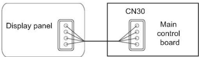
flowchart
graph LR
    A["Display panel"] --> B["CN30"]
    B --> C["Main control board"]
② Switch module connection
Expansion boards can communicate with the main control board through the Switch board. Use one or both of the two expansion boards. The wiring figures are as follows:
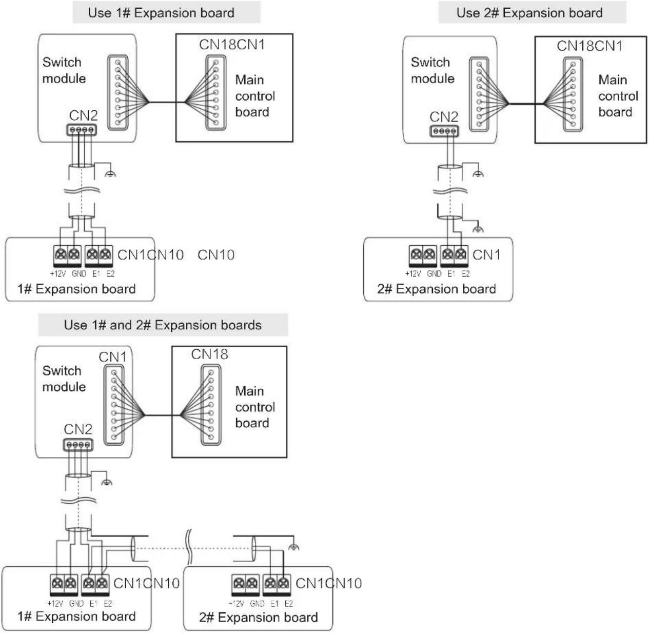
flowchart
graph TD
    subgraph "Use 1# Expansion board"
        A["Switch module"] --> B["CN2"]
        B --> C["+12V GND E1 E2"]
        D["1# Expansion board"] --> E["CN1CN10"]
        E --> F["CN10"]
        G["Switch module"] --> H["CN18CN1 Main control board"]
        H --> I["Main control board"]
    end

    subgraph "Use 2# Expansion board"
        J["Switch module"] --> K["CN2"]
        K --> L["+12V GND E1 E2"]
        M["2# Expansion board"] --> N["CN1"]
        N --> O["Main control board"]
    end

    style A fill:#f9f,stroke:#333
    style D fill:#f9f,stroke:#333
    style M fill:#f9f,stroke:#333
    style J fill:#f9f,stroke:#333

NOTE
For the function introduction of the Switch module, 1# Expansion boards and 2# Expansion boards, please refer to the function module manual.

Alarm signal and Sterilization module
Refer to the following figure for the wiring of alarm signal and Sterilization module.

CAUTION
The output voltage is 220-240V\~.
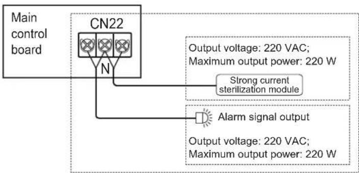
flowchart
graph TD
    A["Main control board"] --> B["CN22"]
    B --> C["Output voltage: 220 VAC; Maximum output power: 220 W"]
    B --> D["Strong current sterilization module"]
    B --> E["Alarm signal output"]
    E --> F["Output voltage: 220 VAC; Maximum output power: 220 W"]

NOTE
The Sterilization function needs to be active by the wired controller, refer to the manual of wired controller for the detail setting.
Other optional in-series equipment may be connected, contact the agent for detail.

Remote On/Off control
Refer to the following figure for using Remote On/Off control.
| Remote Switch Air Conditioning System | |
| On | Off |
| Off | On |
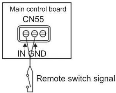

NOTE
The priority of remote control is higher than that of the wired controller.
More remote control functions, such as delayed control, air conditioning system is on when remote control is on, please refer to the manual of wired controller.

Reclose the electric control box cover
Straighten out the connecting wires and lay them flat, and close the electric control box cover again.
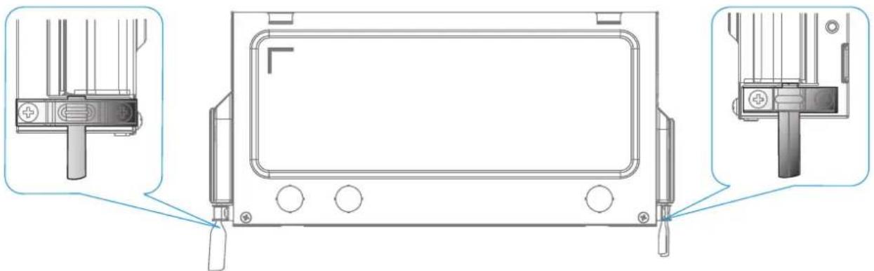
natural_image
Technical line drawing of a device front panel with three close-up views (no text or symbols)
CAUTION
Do not cover the electric control box during power-on.
When covering the electric control box, arrange the cables carefully and do not clip the connecting wires on the electric control box cover.
Error Codes And Definitions
The error code is displayed on the display box and the wired controller display.
| Definition | Error code | Digital display |
| Emergency stop | A01 |  |
| R32 refrigerant leaks, ⚠️ DANGER requiring shutdown immediately | A11 | 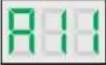 |
| Outdoor unit fault | A51 |  |
| Interlocking control Heat Recovery Ventilation Unit fault( in-series application) | A71 |  |
| The Humidity Unit fault | A72 |  |
| Interlocking control Heat Recovery Ventilation Unit fault (non-serial application) | A73 |  |
| The AHU Kit slave unit fault | A74 |  |
| Self-check fault | A81 |  |
| MS (refrigerant flow direction switching device) fault | A82 |  |
| Mode conflict | A91 |  |
| 1# EEV coil fault | b11 |  |
| 1# EEV body fault | b12 |  |
| 2# EEV coil fault | b13 |  |
| 2# EEV body fault | b14 |  |
| Protection on 1# water pump | b34 |  |
| Protection on 2# water pump | b35 |  |
| Water level switch alarm | b36 |  |
| Reheating electric heater fault | b71 |  |
| Preprocessing electric heater fault | b72 |  |
| Humidifier fault | b81 |  |
| Duplicate indoor unit address code | C11 |  |
| Abnormal communication between the indoor unit and outdoor unit | C21 |  |
| Abnormal communication between the indoor unit main control board and fan drive board | C41 |  |
| Abnormal communication between the indoor unit and wired controller | C51 |  |
| Abnormal communication between the indoor unit and Wi-Fi Kit | C52 |  |
| Abnormal communication between the indoor unit main control board and display board | C61 |  |
| Abnormal communication between the AHU Kit slave unit and master unit | C71 |  |
| Number of AHU Kits is not the same as the set number | C72 |  |
| Abnormal communication between the linked humidifying indoor unit and master indoor unit | C73 |  |
| Abnormal communication between the linked FAPU and master indoor unit (series setting) | C74 |  |
| Abnormal communication between the linked FAPU and master indoor unit (non-series setting) | C75 |  |
| Abnormal communication between the main wired controller and secondary wired controller | C76 |  |
| Abnormal communication between the indoor unit main control board and 1# Expansion board | C77 |  |
| Abnormal communication between the indoor unit main control board and 2# Expansion board | C78 |  |
| Abnormal communication between the indoor unit main control board and Switch board | C79 |  |
| The indoor unit is in power-off state | C81 |  |
| Air inlet temperature of the indoor unit is too low in heating mode | d16 |  |
| Air inlet temperature of the indoor unit is too high in cooling mode | d17 |  |
| Alarm for exceeding temperature and humidity range | d81 | 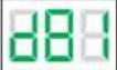 |
| Sensor control board fault | dE1 |  |
| PM2.5 sensor fault | dE2 |  |
| CO2 sensor fault | dE3 | 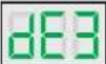 |
| Formaldehyde sensor fault | dE4 | 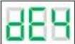 |
| Human Detect sensor fault | dE5 |  |
| T0 (fresh inlet air temperature sensor) short-circuits or cuts off | E21 | 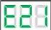 |
| The upper dry bulb temperature sensor short-circuits or cuts off | E22 |  |
| The lower dry bulb temperature sensor short-circuits or cuts off | E23 |  |
| T1 (Indoor unit return air temperature sensor) short-circuits or cuts off | E24 |  |
| The built-in room temperature sensor of the wired controller short-circuits or cuts off | E31 |  |
| The wireless temperature sensor short-circuits or cuts off | E32 |  |
| The external room temperature sensor short-circuits or cuts off | E33 |  |
| Tcp (pre-cooled fresh air temperature sensor) short-circuits or cuts off | E61 |  |
| Tph (pre-heated fresh air temperature sensor) short-circuits or cuts off | E62 |  |
| TA (outlet air temperature sensor) short-circuits or cuts off | E81 | 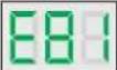 |
| Outlet air humidity sensor fault | EA1 |  |
| Return air humidity sensor fault | EA2 | 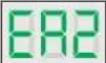 |
| Upper wet bulb sensor fault | EA3 |  |
| Lower wet bulb sensor fault | EA4 |  |
| R32 refrigerant leakage sensor fault | EC1 |  |
| T2A (heat exchanger inlet temperature sensor) short-circuits or cuts off | F01 |  |
| T2 (heat exchanger middle temperature sensor) short-circuits or cuts off | F11 | 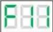 |
| T2 (heat exchanger middle temperature sensor) overtemperature protection | F12 |  |
| T2B (heat exchanger outlet temperature sensor) short-circuits or cuts off | F21 |  |
| Fan drive board input side overcurrent protection | P31 | 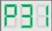 |
| At least 6 times P31 fault codes detected within 60 minutes | P34 |  |
| Power supply voltage is too low fault | P52 |  |
| Main control board EEPROM fault | P71 |  |
| Indoor unit display control board EEPROM fault | P72 |  |
| Locked (electronic lock) | U01 |  |
| Unit model code not set | U11 |  |
| Capacity(HP) code not set | U12 |  |
| Capacity(HP) code setting error | U14 |  |
| AHU Kit fan control input signal DIP setting error | U15 |  |
| Address code not detected | U38 |  |
| Motor failed more than once | J01 | 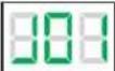 |
| IPM (fan module) overcurrent protection | J1E |  |
| Instantaneous overcurrent protection for phase current | J11 | 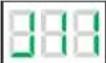 |
| Low bus voltage fault | J3E | 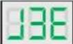 |
| High bus voltage fault | J31 | 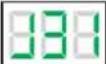 |
| Phase current sample bias error | J43 |  |
| Motor and indoor unit are unmatched | J45 |  |
| IPM and indoor unit are unmatched | J47 |  |
| Motor startup failure | J5E |  |
| Motor blocking protection | J52 |  |
| Speed control mode setting error | J55 |  |
| Phase lack protection of motor | J6E |  |
Operating Status Codes And Definitions (Non-error)
| Definition | Code | Digital display |
| Oil return or preheating operation | d0 |  |
| Self-cleaning | dC |  |
| Mode conflict | dd |  |
| Defrosting | dF |  |
| Static pressure detection | d51 |  |
| Remote shutdown | d61 |  |
| Indoor unit backup operation | d71 |  |
| outdoor unit backup operation | d72 |  |
| Main control program upgrading | OTA |  |

CAUTION
Error codes are displayed only for certain outdoor unit models and indoor unit configurations (including the wired controller and display box).
When the main control program is being upgraded, make sure that the indoor unit and outdoor unit remain powered on. Otherwise, the upgrading process will stop.
Spot Check Description
Use the bi-directional communication wired controller (for example, WDC3-86S) to activate the spot check function in the following steps:
① On the main page, hold "≡" and "▲" for 2s to enter the query page. The wired controller displays "CC". Press "▲" or "▼" key to select the indoor unit address n00-n74 (indicating the address of a specific indoor unit), and press the "≡" key to enter the parameter query page.
② Press the "▲" or "▼" key to query the parameters, and the parameters can be queried cyclically. See the spot check list below for details.
③ Press the " ℓ" key to exit the query function.
④ On the top of the query page, the "Timing area" displays the spot check serial number, and the "Temperature area" displays the content of the spot check parameters.
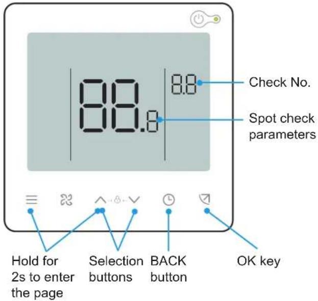
| No. | Displayed content Displayed contentNo. | ||
| 1 | Indoor unit address | 11 | Actual RH indoor humidity |
| 2 | Capacity HP of indoor unit | 12 | Actual fresh air processing unit TA air supply temperature |
| 3 | Actual set temperature Ts | ||
| 4 | Set temperature of the unit that is operating currently, Ts (Remarks: The temperature displayed is the actual set temperature Ts) | 13 | Air-blow pipe temperature |
| 14 | Compressor discharge temperature | ||
| 15 | Target superheat | ||
| 5 | Actual T1 indoor temperature | 16 | EXV opening (actual opening/8) |
| 6 | Modified indoor temperature T1_modify | 17 | Software version No. |
| 7 | T2 heat exchanger intermediate temperature | 18 | Historical error code (recent) |
| 8 | T2A heat exchanger liquid pipe temperature | 19 | Historical error code (sub-recent) |
| 9 | T2B heat exchanger gas pipe temperature | 20 | Fan drive version No. |
| 10 | Actual set humidity RHs | 21 | [———] is displayed |
ESP Setting
Use the bi-directional communication wired controller (for example, WDC3-86S) to set the unit external static pressure:
1
Constant speed mode
The bi-directional communication wired controller must be used to set the unit external static pressure parameters to overcome the air outlet resistance. The steps are as follows:
① On the main page, hold "≡" and "↗" for 3s. The wired controller displays "CC". Press the "▲" or "▼" key to select the indoor unit address n00-n63 (indicating the address of a specific indoor unit), and press the "↗" key to enter the parameter setting page. The wired controller displays "n00".
② On the parameter setting page, press the "▲" and "▼" keys to switch the "Parameter code" to the initial static pressure detection code "n58", press "→" key to enter the specific parameter setting, and then press "▲" and "▼" to set the parameter value to "01". Then, press the "→" key to save the settings. Then the wired controller will send the initial static pressure detection command to indoor units. Wait a few minutes for the indoor unit to complete the initial static pressure detection.
③ Press " ℓ " to return to the previous page until exiting the parameter settings or perform no operations for 60s and the system will automatically exit the parameter settings.
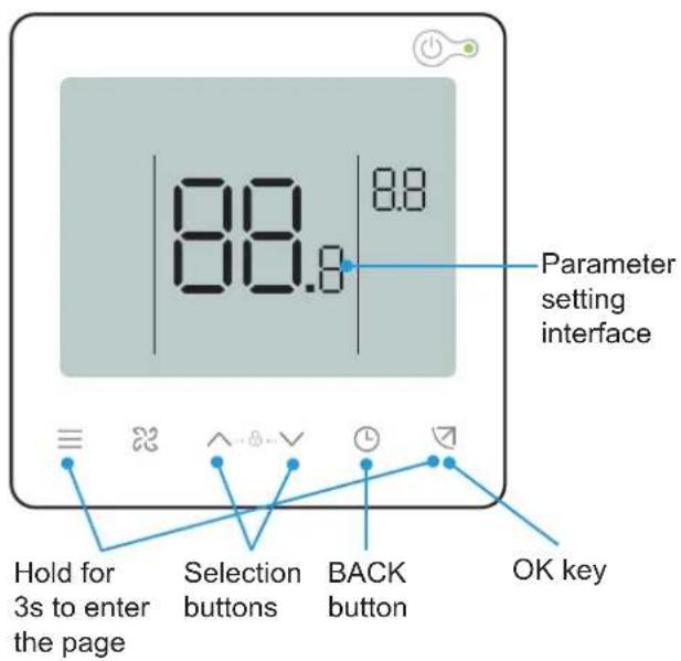
| Parameter code | Parameter name | Parameter range | Default value | Remarks | |
| n00 | Unit external static pressure | Unit external static pressure: 01/02/03/04/05/~/19 | 00 | The indoor unit sets the selected corresponding static pressure value FF. | |
Static pressure setting parameter table
| Unit power | Static pressure settings | |||||||
| W*100 | Level 0 | Level 1 | Level 2 | Level 3 | Level 4 | Level 5 | Level 6 | Level 7-19 |
| HP | Pa | Pa | Pa | Pa | Pa | Pa | Pa | Pa |
| 15 (0.6HP) | ||||||||
| 22 (0.8HP) | ||||||||
| 28 (1.0HP) | ||||||||
| 36 (1.2HP) | 0 | 5 | 10 | 15 | 20 | 25 | 30 | 30 |
| 45 (1.7HP) | ||||||||
| 56 (2.0HP) | ||||||||
| 63 (2.2HP) | ||||||||

NOTE
Parameters can be set while the unit is powered on or powered off.
On the parameter setting page, the wired controller does not respond to a remote signal, and does not respond to the app remote control signal.
When it is in the parameter settings page, the mode, fan speed, and switch buttons are invalid.
Please refer to the remote controller manual for the setting parameters of the remote controller.
For other indoor unit parameter settings, please refer to the manual of the wired controller.
10 Test Run
Checklist Before Test Run
After the installation of the unit, check the items listed below first.

CAUTION
Do not power on the system.
| Check listPass/Fail | |
| Read the complete installation and operation manual. | |
| Installation | |
| Check that the units are properly installed, to avoid abnormal noises and vibrations when starting up the units. | |
| Compressor and others shipping brackets removed. | |
| ‘The Piping Length’ and ‘Additional Refrigerant Charge’ are calculated and recorded on the table of the unit. | |
| Be sure that the stop valves are open on both liquid and gas side. | |
| All Controllers installed and all control wiring is installed and properly connected at each terminal block. | |
| All drain piping is connected, including indoor units tie-in, and insulated as required. | |
| Refrigerant lines are completely insulated including flare nut connections at Indoor Units. | |
| All ductwork is connected and air filters installed. | |
| Air inlet/outlet | |
| Check that the air inlet and outlet of the unit is not obstructed by paper sheets, cardboard, or any other material. | |
| Field wiring | |
| Be sure that the field wiring has been carried out according to the instructions described in the manual and according to the applicable legislation. | |
| Earth wiring | |
| Be sure that the earth wires have been connected properly and that the earth terminals are tightened. | |
| Insulation test of the main power circuit | |
| Using a megatester for 500 V, check that the insulation resistance of 2 MΩ or more is attained by applying a voltage of 500 V DC between power terminals and earth. | |
| NEVER use the megatester for the communication wiring. | |
| Fuses, circuit breakers, or protection devices | |
| Check that the fuses, circuit breakers, or the locally installed protection devices are of the specified size and type. Do not bypass a fuse and a protection device. | |
| Internal wiring | |
| Visually check the electrical component box and the inside of the unit for loose connections or damaged electrical components.Components damageCheck for damaged components and extruded piping inside the unit.Consistency Check between Refrigeration Pipelines and Communication LinesCheck and confirm that the refrigerant piping and communication lines connected to the indoor and outdoor units are belong to the same refrigeration system. | |
| Oil leakCheck if there is oil leaking from the compressor and piping.If there is an oil leak, try to repair the leak. If the repair is not successful, please call the local agent. | |
| Refrigerant leakCheck for refrigerant leaks inside the unit. If there is a refrigerant leak, try to repair the leak. If the repair is not successful, please call the local agent.Do not come into contact with the refrigerant leaking from the refrigerant piping connections. It may cause frostbite. | |
| Flammable refrigerant.If there is a refrigerant leak, keep ventilation to avoid the risk of refrigerant stagnating.If a leak is suspected, all naked flames shall be removed/extinguished.If a leakage of refrigerant is found which requires brazing, all of the refrigerant shall be recovered from the system, or isolated (by means of shut off valves) in a part of the system remote from the leak. | |
| Line Voltage is checked and verified to be within specified range for all system components. | |
| Power the outdoor units 12 hours before operation in order to have power running to the crankcase heater and to protect the compressor. |
Indoor Unit
- The wired/remote controller switch is operating normally.
- The display of the wired/remote controller is normal, the function keys work normally, the room temperature adjustment is normal, and the air flow and direction adjustment are normal.
• The LED indicator is on.
• Water drainage is normal. - Check the indoor units one by one for normal operation, and the cooling and heating functions are normal without vibration or abnormal sound.
Outdoor Unit
• There are no vibrations or strange sounds during operation.
- The fan, noise and condensation do not affect the neighbors.
• There is no refrigerant leakage.

NOTE
Refer to the "Symptoms That Are Not Faults" in the "Operation" in this manual.
Maintenance And Service
1 Safety Warning
WARNING
For safety reasons, always turn off the air conditioner and turn off the power before cleaning the air conditioner.
Do not disassemble or repair the air conditioner by yourself; otherwise, it may cause fire or other hazards.
Only professional service personnel can carry out the maintenance.
Do not use flammable or explosive materials (such as hair styling agents or pesticides) near the product.
Do not use organic solvents such as paint thinner to clean this product; otherwise, it may cause cracks, electric shock or fire.
Only qualified dealers and professionally qualified electricians can install the optional accessories.
Be sure to use the optional accessories specified by local dealer.
Improper installation by yourself may result in water leakage, electric shock or fire.
Do not wash the air conditioner with water; otherwise, it may cause an electric shock.
Use a stable standing platform.
2 Cleaning
Cleaning The Air Filter
CAUTION
The primary efficiency filter is a standard accessory, and the medium efficiency filter is an optional accessory.
Air filters can be used to remove dust or other particles from the air, and if clogged, the effectiveness of the air conditioner will be greatly reduced.
Therefore, be sure to clean the air filter frequently when using it for an extended period.
For the indoor unit with constant speed mode, if it is installed in a place with a lot of dust, it is recommended that you clean the filter once a month.
If excess dirt makes the filter difficult to clean, replace the filter.
Do not remove the air filter unless it is being cleaned; otherwise, it may cause malfunction.
If the air conditioner is used without an air filter, the accumulation of dust in the air conditioner will often cause malfunctions due to the failure to remove dust from the indoor air.
1 Procedure
Remove the air inlet grille.
① Press the grille clamp with two fingers at the same time, and pull out the air inlet grille in a downward direction.
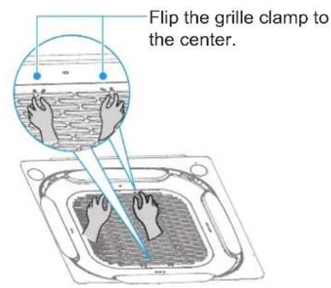
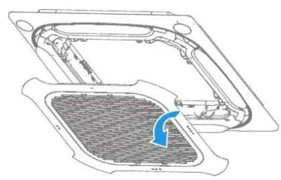
natural_image
Technical line drawing of a mechanical component with a blue arrow indicating rotation or movement (no text or symbols present)② Remove the filter.
NOTE
Only authorised installer or service agent can change and disassemble the filter. Any improper operations may cause electric shock or injuries due to touching rotating parts.
③ Clean the filter.
Clean the filter with a vacuum cleaner, with the air inlet side of the filter facing upwards.
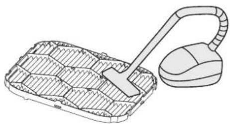
natural_image
Line drawing of a vacuum cleaner next to a plastic tray with internal compartments (no text or symbols)Clean the filter with clean water (except for the activated carbon module), with the air inlet side of the filter facing downwards.
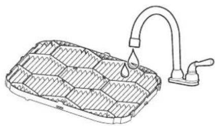
natural_image
Line drawing of a water drain with a curved pipe and handle, no text or symbols presentCAUTION
To avoid deformation of the filter, do not use fire or a burning appliance to dry the filter.
If the filter is dirty, use a soft brush and neutral detergent to clean it, then shake off the water and dry it in a cool place.
Non-professionals should not disassemble, replace or repair the filter.
④ Reinstall the filter.
⑤ Reinstall and close the air inlet grille by following steps 1 and 2 above in reverse.
Cleaning Air Outlets And Exterior Panels
① Wipe the air outlet and panel with a dry cloth.
② If a stain is hard to remove, clean it with clean water or neutral detergent.
CAUTION
Do not use gasoline, benzene, volatile agents, decontamination powder or liquid insecticides. Otherwise, the air outlet or panel may become discolored or deformed.
Do not expose the inside of the indoor unit to moisture, as it may result in electric shock or fire.
When cleaning the louver with water, do not scrub it violently.
If the air conditioner is used without an air filter, the accumulation of dust in the air conditioner will often cause malfunctions due to the failure to remove dust from the indoor air.
Maintenance
During in-depth maintenance, the air conditioner should be cleaned and maintained by professional technicians every 2 to 3 years.
For the indoor unit in constant speed mode, the primary efficiency filter is usually cleaned every three months.
When operating in a dusty environment, the air flow and capacity of the filter will decrease. The filter may even become blocked, and the air conditioner performance and indoor air compromised.
Preheat the unit in advance.
When the heating season comes, power on the outdoor unit master unit for preheating more than 12 hours before use. The preheating time depends on the weather temperature. This can make the air conditioner operate more stably and help the refrigeration oil in the air conditioner compressor to maintain the best lubrication state, which can prolong the service life of the compressor.
Complete the following steps before the air conditioner is put out of use for a long period:
① If the air conditioner is not in use for a long time due to seasonal changes, keep the unit running for 4-5 hours in fan mode until the unit becomes completely dry. Otherwise, it may grow mold indoors and have negative health effects.
② When not in use for a long time, power off or unplug the power plug to reduce standby power consumption, and wipe the wireless remote controller with a clean soft dry cloth and remove the battery.
③ Turn on the power switch 12 hours before using the air conditioner again. In addition, in seasons when air conditioners are frequently used, keep the power switch on. Otherwise, failures may occur.
CAUTION
Before the air conditioner is idle for a long time, the internal components of the outdoor units should be checked and cleaned regularly. For more details, please contact the local air conditioner customer service center or special technical service department.
Check the return air inlet and outlet of the outdoor unit and indoor unit after long periods of use to see if they are blocked; if an inlet/outlet is blocked, clean it immediately.
Wooden buildings, newly renovated houses, and frequent use of disinfectants may contain acidic components in the air, such as formic acid, acetic acid, and hypochlorous acid, which can corrode copper pipes and solder joints, leading to refrigerant leaks.
Factories, chemical plants, livestock farms, vegetable markets, sewage pits, and other environments may contain sulfides, acid gases such as sulfur dioxide, ammonia, and chlorides in the air, which can corrode copper pipes and solder joints, leading to refrigerant leaks.
These places may cause corrosion to the copper pipes and joints of the indoor unit, and it is necessary to have a professional inspection every six months.
3 Service
Step To Dismantle The Electric Control Board
1 Open the electric control box cover.
Remove the two screws at the positions shown in the figure, and pull out the bottom end of the electric control box cover horizontally. Remove the electric control box cover in a downward direction.
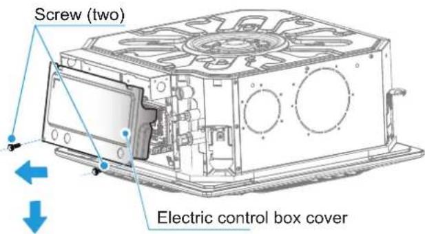
2 Remove the main control board.
Unplug the terminals on the main control board and remove the screws at the positions shown in the figure.
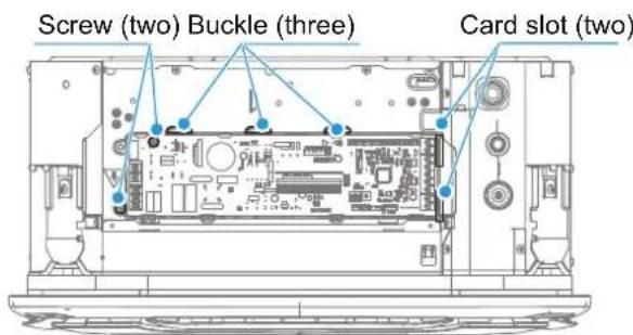
Step To Dismantle The Fan
1 Move the four buckle positions to remove the panel enclosure.
Pinch the two sets of grille clamps at the same time, then lift them to remove the air inlet grille.
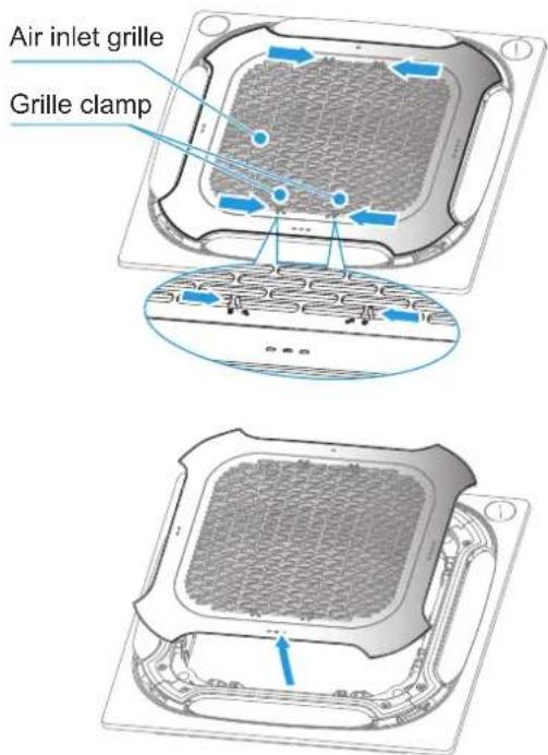
2 Remove the four fixing screws and remove the panel.
Remove the screws at the position shown in the figure, disconnect the panel communication wiring terminal, release the panel hook, and remove the panel.
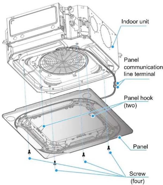
3 Open the electric control box cover and untie the cable tie.

5 Remove the upper sealing plate. Remove the screws at the position shown in the figure, release the buckle, and remove the drain pan assembly.
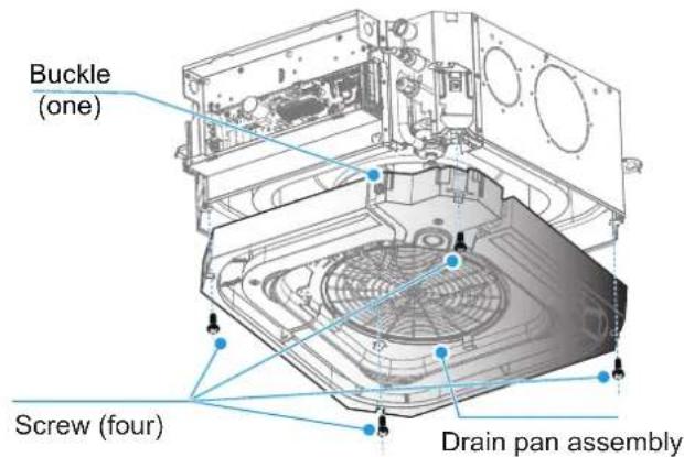
4 Remove the sealing plate assembly. Remove the screws at the position shown in the figure, remove the sealing plate assembly, and loosen the wire binding sponge at the outlet.
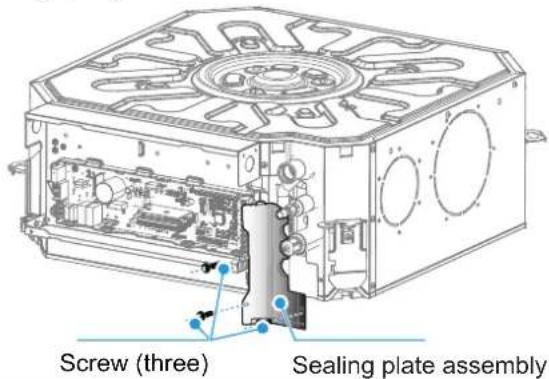
6 Replace the fan after removing the nuts at the center of the fan and the fan clip. Remove the nuts with flat washers and the fan clip at the position shown in the figure, and remove the centrifugal fan.
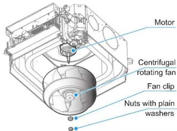
Step To Dismantle The Main Motor
1 Follow the steps above to remove the fan.
2 Unplug the motor terminal on the main control board.
Unplug the motor wiring terminal on the main control board at the position shown in the figure.
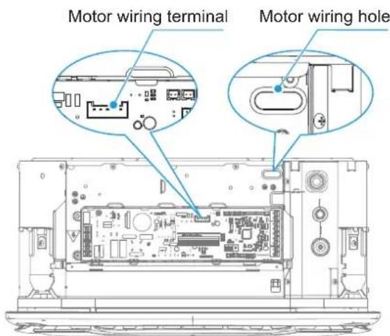
4 Replace and install motor in reverse order.
3 After removing the three bolts securing the motor in place, pull out the terminal according to the motor wiring path. Remove the three motor bolts at the positions shown in the figure, pull out the terminal according to the motor wire path, and remove the motor.
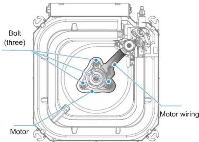
Step To Dismantle The Evaporator
1 Unplug the corresponding terminals on the main control board.
2 Follow the steps above to remove the panel and drain pan.
3 Remove the sealing plate assembly.
4 After removing one fixing screw, remove the evaporator fixing board.
Remove the evaporator hook screws and remove the evaporator hook.
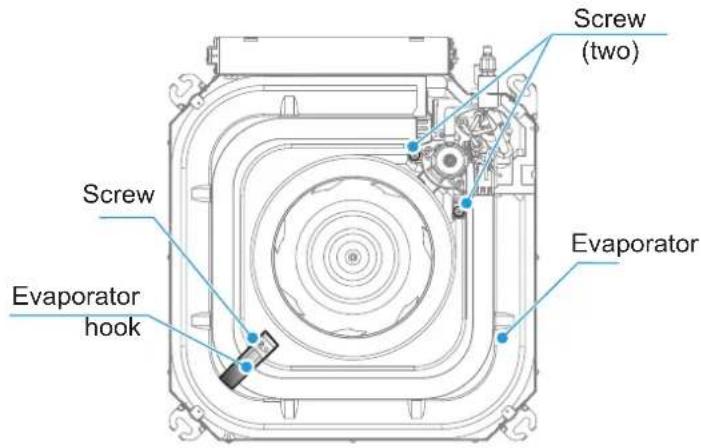
Remove the screws fixing the evaporator and the pump bracket in place, and remove the evaporator.
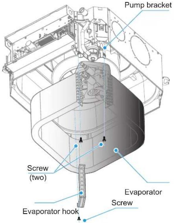
5 Remove the evaporator as a whole.
Step To Dismantle The Water Pump
1 Unplug the water pump terminal on the main control board.
2 Follow the steps above to remove the panel and drain pan.
3 Unplug the drain pipe.
4 After removing the two fixing screws, the pump can be taken out for replacement or maintenance.
Touch the drain pipe clasp and unplug the drain pipe.
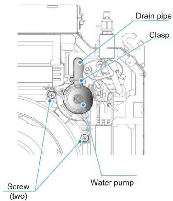
Remove the screws fixing the water pump and the pump bracket in place, and remove the water pump.
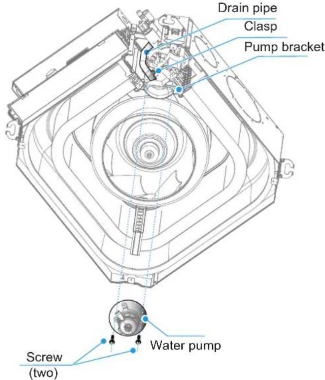

Multi-languages
技术要求,此页不做菲林
封面封底为铜版纸105g,内页为双胶纸80g
210*297mm,黑白印刷
A-B
整本说明书重新翻译
B-C