Core 500i - Processor QSC - Free user manual and instructions
Find the device manual for free Core 500i QSC in PDF.


| Product Type | Digital Audio Processor |
| Brand | QSC |
| Model | Core 500i |
| Form Factor | 1U Rack-Mountable |
| Width | 19 inches (48.3 cm) |
| Depth | 10 inches (25.4 cm) |
| Height | 1.75 inches (4.45 cm) |
| Weight | 8 lbs (3.6 kg) |
| Power Supply | 100-240V AC, 50-60 Hz, 50W |
| Audio Channels | 12 inputs, 8 outputs |
| Processing Power | DSP with 64-bit floating point |
| Main Functions | Audio processing, mixing, routing, EQ, dynamics, delay, matrix mixing |
| Supported Features | Dante networking, AES67, analog and digital I/O, GPIO |
| Control | Web-based interface, QSC Q-SYS software |
| Network | Ethernet for control and audio |
| Operating Temperature | 0°C to 40°C (32°F to 104°F) |
| Care and Cleaning | Wipe with a dry, soft cloth. Do not use liquids or solvents. |
| Safety | Do not expose to moisture, ensure proper ventilation. |
| Spare Parts | Contact QSC authorized service centers for replacement parts. |
| Repairability | Service by qualified technicians only. No user-serviceable parts inside. |
Frequently Asked Questions - Core 500i QSC
User questions about Core 500i QSC
0 question about this device. Answer the ones you know or ask your own.
Ask a new question about this device
Download the instructions for your Processor in PDF format for free! Find your manual Core 500i - QSC and take your electronic device back in hand. On this page are published all the documents necessary for the use of your device. Core 500i by QSC.
USER MANUAL Core 500i QSC
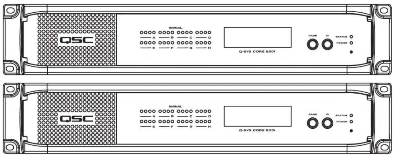
Core 250i – Networked audio and control processor and input and output device
Core 500i – Networked audio and control processor and input and output device
EXPLANATION OF TERMS AND SYMBOLS
The term "WARNING!" indicates instructions regarding personal safety. If the instructions are not followed the result may be bodily injury or death.
The term "CAUTION!" indicates instructions regarding possible damage to physical equipment. If these instructions are not followed, it may result in damage to the equipment that may not be covered under the warranty.
The term "IMPORTANT!" indicates instructions or information that are vital to the successful completion of the procedure.
The term "NOTE" is used to indicate additional useful information.

The intent of the lightning flash with arrowhead symbol in a triangle is to alert the user to the presence of un-insulated "dangerous" voltage within the product's enclosure that may be of sufficient magnitude to constitute a risk of electric shock to humans.

The intent of the exclamation point within an equilateral triangle is to alert the user to the presence of important safety, and operating and maintenance instructions in this manual.

IMPORTANT SAFETY INSTRUCTIONS


WARNING!: TO PREVENT FIRE OR ELECTRIC SHOCK, DO NOT EXPOSE THIS EQUIPMENT TO RAIN OR MOISTURE. Ensure reliable earth grounding is maintained. – Distribute the units evenly when installing in a rack. Hazardous conditions can be created by uneven weight distribution.
- Read these instructions.
- Keep these instructions.
- Heed all warnings.
- Follow all instructions.
- Do not use this apparatus near water.
- Clean only with a dry cloth.
- Do not block any ventilation opening. Install in accordance with the manufacturer's instructions.
- Do not install near any heat sources such as radiators, heat registers, stoves, or other apparatus (including amplifiers) that produce heat.
- Do not defeat the safety purpose of the polarized or grounding-type plug. A polarized plug has two blades with one wider than the other. A grounding type plug has two blades and a third grounding prong. The wide blade or the third prong are provided for your safety. If the provided plug does not fit into your outlet, consult an electrician for replacement of the obsolete outlet.
- Protect the power cord from being walked on or pinched particularly at plugs, convenience receptacles, and the point where they exit from the apparatus.
- Only use attachments/accessories specified by the manufacturer.
- Unplug this apparatus during lightning storms or when unused for long periods of time.
- Refer all servicing to qualified service personnel. Servicing is required when the apparatus has been damaged in any way, such as power-supply cord or plug is damaged, liquid has been spilled or objects have fallen into the apparatus, the apparatus has been exposed to rain or moisture, does not operate normally, or has been dropped.
- The AC power cord is the AC mains disconnect device and shall remain readily accessible after installation.
- Adhere to all applicable, local codes.
- Consult a licensed, professional engineer when any doubt or questions arise regarding a physical equipment installation.
LITHIUM BATTERY WARNING

WARNING!: THIS EQUIPMENT MAY CONTAIN A NON-RECHARGEABLE LITHIUM BATTERY. LITHIUM IS A CHEMICAL KNOWN TO THE STATE OF CALIFORNIA TO CAUSE CANCER OR BIRTH DEFECTS. THE NON-RECHARGEABLE LITHIUM BATTERY CONTAINED IN THIS EQUIPMENT MAY EXPLODE IF IT IS EXPOSED TO FIRE OR EXTREME HEAT. DO NOT SHORT CIRCUIT THE BATTERY. DO NOT ATTEMPT TO RECHARGE THE NON-RECHARGEABLE LITHIUM BATTERY. THERE IS A RISK OF EXPLOSION IF THE BATTERY IS REPLACED BY AN INCORRECT TYPE. DISPOSE OF USED BATTERIES ACCORDING TO THE INSTRUCTIONS.
FCC Statement

NOTE: This equipment has been tested and found to comply with the limits for a Class B digital device, pursuant to Part 15 of the FCC Rules.
NOTE: These limits are designed to provide reasonable protection against harmful interference in a residential installation. This equipment generates, uses and can radiate radio frequency energy and, if not installed and used in accordance with the instructions, may cause harmful interference to radio communications. However, there is no guarantee that interference will not occur in a particular installation. If this equipment does cause harmful interference to radio or television reception, which can be determined by turning the equipment off and on, the user is encouraged to try to correct the interference by one or more of the following measures:
- Reorient or relocate the receiving antenna.
- Increase the separation between the equipment and receiver.
- Connect the equipment into an outlet on a circuit different from that to which the receiver is connected.
- Consult the dealer or an experienced radio/TV technician for help.
Warranty (USA only; other countries, see your dealer or distributor)
Disclaimer
QSC Audio Products, LLC ("QSC") is not liable for any damage to amplifiers, loudspeakers, or any other equipment that is caused by negligence or improper installation and/or use of this signal processing product. While QSC has endeavored to develop and produce the most dependable and robust network audio product for your use, due to the myriad of network situations and equipment that may be encountered in its implementation, QSC cannot be held responsible for network conflicts and associated consequences that may result. For this reason, QSC strongly recommends that the network used for implementation of Q-Sys products be completely separate from all other networks, data or otherwise. As such, should you elect to integrate Q-Sys products with your existing network system, all risks attendant to such integration of Q-Sys products with your existing network or network systems are assumed by you. While QSC strives to provide the highest quality technical solutions for networked audio products, in no event will QSC or its suppliers be held liable for any damages, consequential, incidental or otherwise, including any claims for lost profits and/or savings resulting from any attempted integration of Q-Sys products with your networking systems. No agent, employee or representative of QSC has any authority to alter or modify in any manner, the disclosures and recommendations set forth herein.
QSC Audio Products 3 Year Limited Warranty
QSC Audio Products, LLC ("QSC") guarantees its products to be free from defective material and/or workmanship and will replace defective parts and repair malfunctioning products under this warranty when the defect occurs under normal installation and use, provided the unit is returned to our factory, one of our authorized service stations or an authorized QSC International Distributor via pre-paid transportation with a copy of proof of purchase (i.e., sales receipt). This warranty provides that the examination of the return product must indicate, in our judgment, a manufacturing defect. This warranty does not extend to any product which has been subjected to misuse, neglect, accident, improper installation, or where the date code has been removed or defaced. QSC shall not be liable for incidental and/or consequential damages. This warranty gives you specific legal rights. This limited warranty is freely transferable during the term of the warranty period. The warranty on QSC products is NOT VALID if the products have been purchased from an unauthorized dealer/online e-tailer, or if the original factory serial number has been removed, defaced, or replaced in any way. Damage to, or loss of any software or data residing on the product is not covered. When providing repair or replacement service, QSC will use reasonable efforts to reinstall the product's original software configuration and subsequent update releases, but will not provide any recovery or transfer of software or data contained on the serviced unit not originally included in the product.
Customers may have additional rights, which vary from state to state or from country to country. In the event that a provision of this limited warranty is void, prohibited or superseded by local laws, the remaining provisions shall remain in effect.
The QSC limited warranty is valid for a period of three (3) years from date of purchase in the United States and many (but not all) other countries.
For QSC warranty information in countries other than the United States, contact your authorized QSC international distributor. A list of QSC International distributors is available at www.qscaudio.com.
To register your QSC product online, go to www.qscaudio.com and select "Product Registration". Other questions regarding this warranty can be answered by calling, e-mailing or contacting your authorized QSC distributor.
Phone: 1-800-854-4079 within US and Canada, +1-714-754-6175 international, Email: warranty@qscaudio.com, Website: www.qscaudio.com.
RoHS Statement
The following chart is provided for product use in China.
| Q-SystM Core 250i 系列, Q-Sys Core 500i | ||||||
| 部件名称(Part Name) | 有毒有害物质或元素(Toxic or hazardous Substances and Elements) | |||||
| 铅(Pb) | 汞(Hg) | 镉(Cd) | 六价铬(Cr(vi)) | 多溴联苯(PBB) | 多溴二苯醚(PBDE) | |
| 电路板组件(PCB Assemblies) | X | O | O | O | O | O |
| 机壳装配件(Chassis Assemblies) | X | O | X | O | O | O |
| 0: 表明这些有毒或有害物质在部件使用的同类材料中的含量是在 SJ/T11363_2006极限的要求之下。O: Indicates that this toxic or hazardous substance contained in all of the homogeneous materials for this part is below the limit requirement in SJ/T11363-2006.X: 表明这些有毒或有害物质在部件使用的同类材料中至少有一种而含量是在SJ/T11363_2006极限的要求之上。X: Indicates that this toxic or hazardous substance contained in at least one of the homogeneous materials used for this part is above the limit requirement in SJ/T11363-2006. | ||||||
Unpacking
There are no special unpacking precautions. However, it is recommended that you keep the original packing materials for reuse in the rare event that service is required. If service is required and the original packing material is not available, ensure that the unit is adequately protected for shipment (use a strong box of appropriate size, sufficient packing/padding material to prevent load shifting or impact damage) or call QSC's Technical Services Group for replacement packing material and a carton.
What is included in your Q-Sys™ product carton:
Q-Sys Core 250i or Core 500i
- Rubber feet
• Q-Sys Hardware User Manual
• Q-Sys Designer software CD
• IEC power cord and cord lock wire - Connector plug kit appropriate for the optional Q-Sys Audio I/O Card(s) ordered
Mounting
Q-Sys products can be used in or out of an equipment rack. Rack mounting is optional. Adhesive rubber feet are included for non-rack mount installations (table or shelf top installations). Use the feet to prevent the unit from scratching or marring the support surface.
Rack Mount Instructions
Rack mount the Q-Sys product by supporting it from underneath while aligning the front panel mounting holes (in the rack ears) with the threaded screw holes in the rack rails. Install all four mounting screws and washers and tighten securely. All Q-Sys products come with rear rack support ears. Ensure that these rear mounting points are securely fastened to rear rack rails or side walls.

WARNING!: Reliable Earthing – Reliable earthing of rack-mounted equipment should be maintained. Particular attention should be given to supply connections other than direct connections to the branch circuit (e.g. use of power strips).
Mechanical Loading – Mounting the equipment in the rack should be done such that a hazardous condition is not achieved due to uneven or unstable mechanical loading.

CAUTION!: Elevated Operating Ambient - If installed in a closed or multi-unit rack assembly, the ambient operating temperature of the rack environment may be greater than room ambient. Consideration should be given to ensure that the maximum operating temperature listed in "Q-Sys Type 2 System Hardware Specifications" on page 15 is not exceeded.
Reduced Air Flow – Installation of the equipment in a rack should be such that the amount of air flow required for safe operation of the equipment is not compromised.
Circuit Overloading – Consideration should be given to the connection of the equipment to the supply circuit and the effect that overloading of the circuits might have on over-current protection and supply wiring.
Connections
AC Power Cord
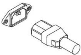
Insert the molded receptacle of the AC power cord into the AC power inlet on the back of the Q-Sys product. (Figure 1) Plug the AC line connector into an AC outlet. The power supply on the Q-Sys Cores accepts 100 – 240 V, 50 – 60 Hz. If a different type of IEC power cord is required than that supplied with the product, consult QSC's Technical Services Group.
Q-Sys™ Network
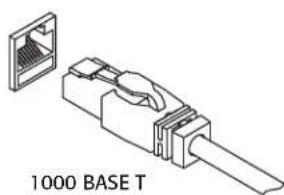
Connect one end of a data communications cable (CAT-6 rating or better) terminated with an RJ45 plug into the LAN A (and optionally LAN B) receptacle on the rear panel of the Q-Sys product. Ensure that the lock tab on the cable engages with the RJ45 receptacle. (Figure 2)
Mic/Line Inputs, Line Outputs, AES3 I/O
Several of the optional audio I/O Cards accept Euro style (also known as Phoenix) three-terminal plugs. (Figure 3) When these cards are ordered in the product configuration a kit containing the mating plugs is included in the carton contents. Plug the Euro terminal block plug into the appropriate input or output receptacle on the Q-Sys Audio I/O Card's panel face. The connection pinout is printed on the Q-Sys Audio I/O Card mounting bracket. Refer to the illustrations in the right-hand column of this page for balanced and unbalanced connections (analog connections only – AES3 connections always require all three conductors).
DataPorts
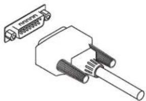
The Q-Sys DataPort I/O Card is intended to interface with QSC amplifiers with v1 DataPorts. This is the all-capable version 1 DataPort specification, supported on CX, DCA, PowerLight™, PL2, and PL3 Series amplifiers. All DataPorts use the HD15 connector format and connect to QSC amplifiers via data communications cables having male HD15 connectors. (Figure 4)

IMPORTANT: These appear to be common VGA cables but they are not. Many off-the-shelf VGA cables MIGHT work with satisfactory results, however it is also quite possible off-the-shelf cables will give less-than-satisfactory results, and could even cause damage to QSC amplifiers! The QSC DataPort specification requires that all conductors be present, as well as shielding over those conductor pairs used for the audio channels to the amplifier. Therefore, QSC recommends the use of QSC DataPort cables exclusively, which are available in a variety of lengths from QSC. Use of any non-QSC DataPort cable may void the warranty.
To connect a DataPort cable between a Q-Sys DataPort I/O Card and an amplifier DataPort, attach the cable's male connectors to the HD15 ports and fi nger tighten the thumb screws on the connector.(Figure 4)
CobraNet
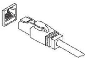
The Q-Sys CobraNet I/O Card is intended to provide an interface between Q-Sys and QSC's Basis, DCP, and third-party CobraNet devices. The connector required is an RJ45. (Figure 5)
natural_image
Technical line drawing of two mechanical components (no text or symbols)- Figure 1 -
natural_image
Technical line drawing of a 1000 base T connector (no text or symbols on the diagram itself)- Figure 2 -
Balanced / AES 3
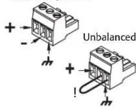
- Figure 3 -
natural_image
Technical line drawing of a mechanical connector with no visible text or symbols- Figure 4 -
natural_image
Isometric line drawing of a connector with an attached socket (no text or symbols)- Figure 5 -
Minimum System Requirements for Q-Sys™ Designer
Q-Sys Designer is the software you use to create the designs for a Q-Sys system. After your system is designed, tested and deployed on the Core, Q-Sys designer is not required for that system to operate. Q-Sys Designer runs in a PC environment with the following minimum requirements.
Software
- Microsoft® Windows® 7
• Microsoft® Windows Vista® SP1 - Microsoft® Windows XP® Professional Version 2002 SP3
- Microsoft® .NET Framework 4.0 Client Profi le
- Microsoft® .NET Framework 4.0 Extended
- Microsoft® Visual C++ 2010 Runtime
• Q-Sys Designer 3.0 or greater
PC Hardware Requirements for Windows Vista Home Premium / Business / Ultimate/ Windows 7
• 1 GHz 32-bit (x86) or 64-bit (x64) processor
- 1 GB of system memory
• 40 GB hard drive with at least 15 GB of available space
• Support for DirectX 9 graphics with:
a. WDDM Driver
b. 128 MB of graphics memory (minimum)
c. Pixel Shader 2.0 in hardware
d. 32 bits per pixel
- CD-ROM or DVD drive
- Keyboard and Microsoft® Mouse or compatible pointing device
PC Hardware Requirements for Windows XP Professional
- PC with 300 megahertz or higher processor clock speed recommended; 233 MHz minimum required (single or dual processor system); Intel® Pentium®/Celeron® family, or AMD K6®/AMD Athlon®/AMD Duron® family, or compatible processor recommended.
• 128 megabytes (MB) of RAM or higher recommended (64 MB minimum supported; may limit performance and some features)
• 1.5 gigabytes (GB) of available hard disk space
• Super VGA (800 x 600) or higher-resolution video adapter and monitor - CD-ROM or DVD drive
- Keyboard and Microsoft® Mouse or compatible pointing device
Installing Q-Sys Designer
- Start your PC.
- Close any running applications.
- If you have an Internet connection, you can download the latest software at www.qscaudio.com/products/software/QSys or place the Q-Sys Designer CD into your CD-ROM/DVD drive.
- The software should auto-run. If not, select run from the start menu. Browse to the file named setup.exe on your CD-ROM/DVD drive
- Click the Install Q-Sys Designer button.
- Follow the on-screen prompts/instructions.
Quick Start Guide
This Quick Start Guide is intended to give a high-level procedure for getting a simple Q-Sys system connected, running a Q-Sys design, and passing audio. The following procedure assumes that you have a Q-Sys Designer file with components properly connected, but not necessarily configured.
- Set up the Q-LAN network. For more information about Network Requirements see Help File Networking Topic; for a list of qualified switches see "Qualified Ethernet Switches" on page 13, or the QSC website (qscaudio.com).
- Connect PC, and Core to the Q-LAN network. If you have any I/O Frames, they should be connected to the Q-LAN network at this time.
- Connect DataPort amplifiers and loudspeakers.
- Power up the equipment.
- On the PC, Start Q-Sys Designer.
a. Open your design fi le.
b. Select the Core in the Inventory list, and verify the configuration. Make sure the Core model is correct, and the correct I/O cards are identified in the same slots as they appear in the physical hardware.
c. Open Q-Sys Configurator and select the Core with the same name as in the design. If the names are different, you must change the hardware name or the name of the Core component in Q-Sys Designer so they match. A new Core is shipped with both LANs enabled, and the addressing Mode set to Auto. The available modes are:
» Auto — If there is a DHCP server on the network, the IP Address is automatically assigned. When a DHCP server is not found or non-functional, and the Q-Sys end node is configured for "auto", it will use Link-Local addressing to self assign an IP address in the 169.254.0.0/16 range.
»Static — You assign a static IP Address, Mask and Default Gateway.
» Off – Available on LAN B only. In the Off mode, there is no network redundancy.
d. If you have any I/O Frames, select them one at a time in the Inventory list, and verify the configuration of each.
e. In Q-Sys Configurator, Select the I/O Frame with the same name as in the design. If the names are different, you must change the hardware name or the name of the I/O Frame component in Q-Sys Designer so they match. A new I/O Frame is shipped with both LANs enabled, and the addressing Mode set to Auto. The available modes are:
» Auto — If there is a DHCP server on the network, the IP Address is automatically assigned. When a DHCP server is not found or non-functional, and the Q-Sys end node is configured for "auto", it will use Link-Local addressing to self assign an IP address in the 169.254.0.0/16 range.
»Static — You assign a static IP Address, Mask and Default Gateway.
»Off — LAN B only, no network redundancy
f. Ensure that the amplifiers are properly connected in the design and configured correctly. The connections and configuration should match the physical connections.
g. Ensure that the loudspeakers are properly connected to the amplifiers in the design, and configured correctly. The connections and configuration should match the physical connections.
h. There are many ways to pass audio through the Q-Sys system, your design should contain one or more ways to do this. If not, refer to the Online Help and add one of the components that would allow you to pass audio.
i. Save the design to the Core and connect (Press F5).
j. If the Core's firmware does not match the firmware embedded in Q-Sys Designer on your PC, you are prompted to update the firmware. The Core 250i and 500i are supported by Q-Sys Designer 3.0 and above. Do not install a version of Q-Sys Designer earlier than 3.0.

NOTE: To download the latest Q-Sys Designer software and firmware, go to http://www.qscaudio.com/products/software/QSys.
- Test the system.
Before trying to pass audio, place the System Mute component in your design, Run the design (F5), and click the Mute button. When you attempt to pass audio for the first time, you can un-mute the system and the output will ramp up to the level of the settings in your design. If the system begins to get too loud, you can press the mute button again and make necessary adjustments.
Overview
Q-Sys™ is an integrated system audio solution. The DSP is centralized to allow faster development and deployment of new features, and requires fewer hardware changes as well. Q-Sys has been designed around four major criteria: Sonic Quality, Reliability, Power and Flexibility.
Type 2 Hardware
Q-Sys has two types of hardware currently deployed. In the Type 2 hardware, new IDC (ribbon type) connectors replaced the FCC (flex type) connectors installed in earlier releases of hardware. Due to this change, the Type 2 hardware is not physically compatible with the older hardware. You can still integrate the new I/O Frames and Cores in the same system with older hardware, but the I/O cards are not interchangeable. Type 2 hardware can be identified by a yellow label (Figure 6) on the back of the Core and I/O Frame, and the bottom of the I/O cards.
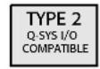
- Figure 6 -
Components
Q-Sys is comprised of the following dedicated components:
- Q-Sys Core (Required) – The Core is the central processing unit of Q-Sys. The Core processes and routes all audio, controls peripheral devices, manages firmware updates to the peripheral devices. The Core 250i and 500i have eight slots available to add the I/O cards listed under Q-Sys I/O Cards below. Because the Cores 250i and 500i can have up to eight I/O cards, it can operate as a stand-alone system. However, you can connect one or more Q-Sys I/O Frames to the Q-LAN network to increase the number of I/O cards available to the Core. Refer to the Hardware User Manual for the Cores 1000, 3000, 4000, and I/O Frame (TD 000284) for information.
-
Q-Sys I/O Card(s) (One or more required) – The I/O cards, installed in the Core, are the links between the input/output devices and the Core. The I/O cards receive audio from external equipment and send it to the Core for processing. They also receive audio from the Core and send it to output devices. The Core houses one or more of the following: (The Core does not necessarily require any I/O cards, you can have an I/O Frame connected to Q-LAN with I/O cards that would fill the requirements.)
-
AES Card – provides the interface between digital devices such as mixing consoles, recording devices, other devices and Q-Sys.
- Blank Card Fills card slot when no card is needed.
CobraNet Card – provides the interface between QSC Basis, DCP, or third-party CobraNet devices. - DataPort Card – provides audio, telemetry, and control interface between Q-Sys and QSC DataPort amplifiers and QSC loudspeakers.
• Line Out Card – provides the interface between third-party amplifiers, recording devices, other devices and Q-Sys. - Standard (Std) or High Performance (HP) Mic/Line Input Card – provides the interface between input devices (microphones, CD/DVD players, mixers, and so on) and Q-Sys.
- Q-Sys Designer Software 3.0 or Greater (Required for designing, not required for operation) – Q-Sys Designer is the design software application that creates the design file that is loaded onto a Q-Sys Core. The design file contains all the virtual components, their connections and initial DSP settings. The design is initially created on a PC running Q-Sys Designer. When the design is complete, it is loaded on the Core and tested, and adjustments made. When all adjustments are finalized, the design is saved to the Core. Q-Sys Designer is not required to operate the Q-Sys system. Q-Sys Designer requires a Windows-based PC running Windows XP, Windows Vista, or Windows 7.
- Gigabit Ethernet Network (Required only if an I/O Frame, I/O-22, or a Page Station is part of your system.) – The Q-Sys solution is designed around a high performance network implementation called Q-LAN that offers gigabit data rates, device and network redundancy, 32-bit floating point audio data transfers, end node discovery and low-latency support on local area network deployments. Additionally, Q-LAN offers long-haul IP streaming of audio over wide area network deployments. Accurate synchronization of end nodes and high-quality clock distribution are built-in to the solution using the IEEE-1588 Precision Time Protocol. All devices are connected to a managed 1000 Mbps Ethernet switch with appropriate QoS (Quality of Service) enabled suitable for a high-performance gigabit network. For complete details refer to the Q-Sys online help. For qualified switch recommendations see “Qualifi ed Ethernet Switches” on page 13.
- Q-Sys I/O Frame (Optional) – Provides up to four additional I/O cards for a Q-Sys System.
- Q-Sys DataPort Amplifi er Backup Panel • DAB-801(Optional) – Provides N+1 Amplifi er redundancy
- Q-Sys I/O-22 (Optional) – Provides microphone and line level inputs, line level outputs, and amplification services for a Q-Sys audio system.
- Q-Sys Touch Screen Controllers (Optional) – Provides End-User touch-screen, wall-mounted control
• Q-Sys Page Stations (Optional) – Q-Sys Page Stations are a networked page station solution that connects to a Q-Sys system via Q-LAN.
Q-Sys is an integrated system designed to work with QSC DataPort amplifiers and QSC loudspeakers and other QSC products to provide system-level telemetry and control. Q-Sys can also be configured with generic amplifiers and/or generic loudspeakers, but there is a loss of functionality when not using QSC compatible hardware.
QSC DataPort Amplifiers
QSC DataPort amplifiers (PowerLight™, CX, PL2, DCA, and PL3) can be used in a Q-Sys system to communicate with the Q-Sys DataPort card and provide critical telemetry information and protection for both the amplifier and any loudspeaker. With QSC loudspeaker connected to a DataPort amplifier and Q-Sys, you get additional information and benefits not available with generic loudspeakers. Generic amplifiers can be used in a Q-Sys system by connecting the amplifier to a Line Out connection; however, there is no telemetry or control of either the amplifier or loudspeakers (even QSC loudspeakers) if Line Out cards are used.
Loudspeakers
Q-Sys, QSC DataPort amplifiers, and QSC loudspeakers work together to form an integrated system that provides specific loudspeaker processing (Intrinsic Correction™), telemetry, and protection for the loudspeaker. You can use generic loudspeakers in a Q-Sys system, however there is no Intrinsic Correction provided.
Redundancy
Q-Sys is capable of several redundant configurations to ensure a high level of overall system reliability.
- 2N Core redundancy – Two Cores, primary and redundant, communicating with each other and peripherals to verify system health, and to synchronize control settings.
- 2N Network redundancy – Two separate networks - In this configuration, you can have each Q-Sys Core and/or I/O Frame connected to both networks.
• 2N I/O redundancy For each I/O Frame, you can have a backup I/O Frame. - N+1 Amplifi er redundancy— One amplifi er can back up from one to eight amplifi ers with the Q-Sys DAB-801 (DataPort Amplifi er Backup).
Network Redundancy
The Core, I/O Frame, I/O-22, and TSC-8 have two network ports, LAN A (primary), and LAN B (backup). The LAN B port on a unit becomes active when it is configured in Q-Sys Designer as "Is Network Redundant" and connected. Because the every unit is configured in the design file, the Core recognizes it as being on LAN B as well as LAN A. During operation, the Core routes audio and control signals to both ports, so if LAN A, or a part of LAN A fails, the Core switches to LAN B with no failover time.
Q-Sys Hardware Redundancy
The Cores and I/O Frames can have backups connected to the network. Both are identified in Q-Sys Designer as being redundant. The backup Core communicates with the primary to ensure it is up to date with any changes made on the primary, and to monitor the primary Core's health. The Core monitors the I/O Frames, if there is a problem detected with the primary I/O Frame, the Core switches to the backup. The audio inputs and outputs of the primary and backup I/O Frames are wired in parallel, meaning that the audio source drives two inputs. The audio outputs of an offline I/O Frame are disconnected by relays, so only the active I/O Frame, in a redundant pair, drives the outputs.
Q-Sys™ Core 250i | Core 500i | Panel Features
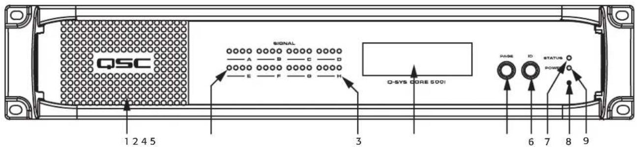
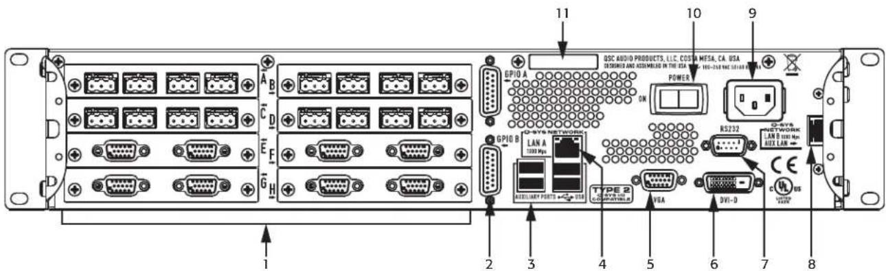
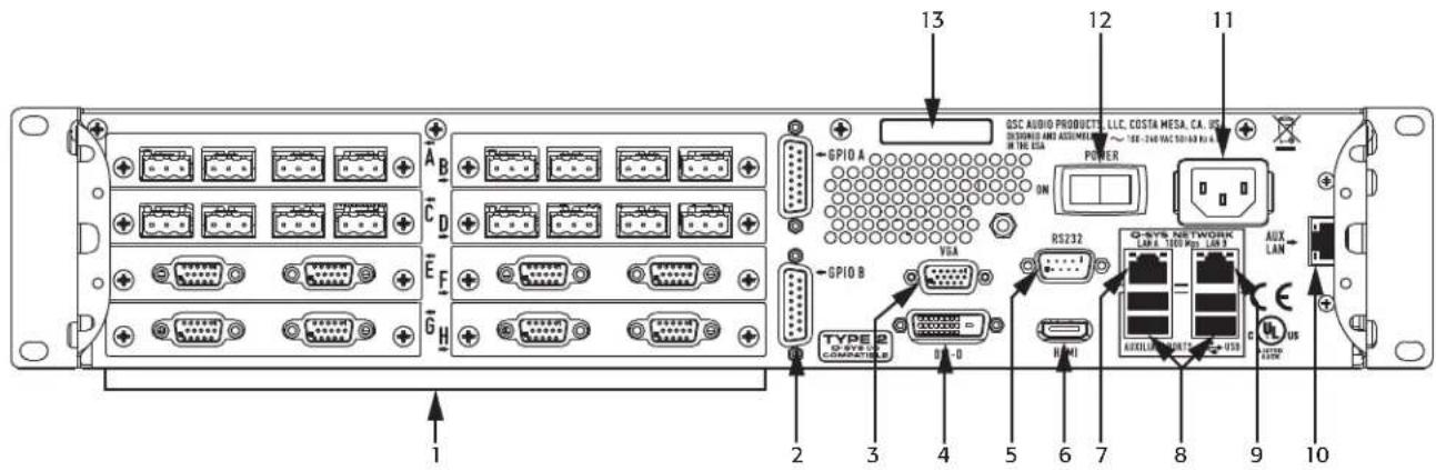
Figure 7, Figure 8, and Figure 9 show the Q-Sys Core front and rear panel features. The front panel is identical for the Core 250i and 500i. The rear panels are shown with all eight I/O cards installed. The cards shown are intended to show all the slots in a populated condition, and not to indicate any particular configuration.

NOTE: The Q-Sys hardware products are configured at the QSC factory per your order. At the time of order, you specify the type of Q-Sys Audio I/O Cards to be installed in the Audio I/O bays on the Q-Sys Core. In addition, Q-Sys Audio I/O Card Kits are available for field installation by qualified service personnel.
Front Panel
-
Figure 7 -
-
Exhaust Vents
- Audio I/O Signal Indicators
- Card Present Indicators
- 240 x 64 Monochrome Graphics LCD (fl ashes when the ID button in Q-Sys Designer or Q-Sys Configurator is pressed.
-
Next Page Navigation Button
-
Device ID Button (locates device in Q-Sys Designer GUI)
- Status LED (reports network health and firmware update status)
- Clear Settings Paperclip Button (resets everything on the Core; does not delete any media files)
- Power On LED
Rear Panel Core 250i
-
Figure 8 -
-
Eight Audio I/O Bays – accepts Q-Sys Type 2 audio I/O cards
- GPIO A and GPIO B Female DA-15 connectors for Q-Sys control I/O
- Four Auxiliary Ports – USB host connectors
- Q-LAN Network Port, LAN A - 1000 Mbps only, primary connection to Q-Sys gigabit network
- Video Out – HD-15 female connector For future use
-
Video Out – DVI female connector For future use
-
RS-232 - DE-9 male connector for serial communications
- Q-LAN Network Port, LAN B or AUX LAN – (1000 Mbps only when used in Q-LAN LAN B mode, 10/100/1000 Mbps when used in AUX mode) backup connection to Q-Sys gigabit network
- AC Main Inlet - IEC male connector with cord retainer
- Power Switch
- Serial Number
Rear Panel Core 500i
-
Figure 9 -
-
Eight Audio I/O Bays – accepts Q-Sys Type 2 audio I/O cards
- GPIO A and GPIO B Female DA-15 connectors for Q-Sys control I/O
- Video Out – HD-15 female connector For future use
- Video Out – DVI female connector For future use
- RS-232 - DE-9 male connector for serial communications
- Video Out – HDMI For future use
-
Q-LAN Network Port, LAN A - 1000 Mbps only, primary connection to Q-Sys gigabit network
-
Four Auxiliary Ports—USB host connectors
- Q-LAN Network Port, LAN B - 1000 Mbps only, backup connection to Q-Sys gigabit network
- AUX LAN Network Port
- AC Main Inlet – IEC male connector with cord retainer
- Power Switch
- Serial Number
Q-Sys™ I/O Card Remove and Replace Procedure
This procedure is for Q-Sys Type 2 I/O Cards only. Card installation should only be done by a trained and qualified technician.
Tools
- Phillips screwdriver
- ESD grounded wrist strap
- 1/4" hex driver/socket (not shown) for replacing Q-Sys I/O Cards in positions C through H.

CAUTION!: An ESD grounded wrist strap must be worn throughout the remove and replace procedure. The end of the wrist strap should be connected to an unpainted surface on the product chassis such as the ground stud.
- Disconnect the AC mains power cord from the Q-Sys Core.
- Connect and put on the ESD grounded wrist strap.
- Remove the sheet metal screws securing the lid to the Q-Sys Core chassis. Remove the lid by lifting it approximately 1" at the rear of the chassis while sliding it towards the back.

NOTE: To remove an I/O Card in a position below the top two positions (A and B), you must fi rst remove the appropriate card(s) above it. The following steps apply to both top and bottom cards.
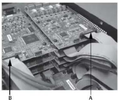
Refer to Figure 10 and Figure 11
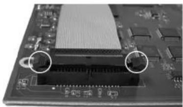
- Locate the I/O Card to be replaced and, except for any Blank Cards, remove the ribbon cable (Figure 11) from the card by gently pushing outward on the cable ejector tabs. The connector should be free of the socket.
- Remove the two screws securing the I/O Card Mounting Bracket (Figure 12) on the rear of the chassis. Remove the bracket.
- Remove the I/O Cards: Refer to Figure 13.
a. For cards in positions A or B, remove the four Phillips head screws securing the card to the standoffs. Remove the card. If you are not replacing a card in position C through H, skip to step 7.

NOTE: Figure 13 shows both standoffs and screws for illustration purposes. The screws are only used on cards in positions A and B. All other cards must use the standoffs.
b. For cards in positions C through H, remove the cards in positions A and/or B (step 6.a), then remove the four hex standoffs securing the next lower card, and remove the card. Continue this until you have removed the card you wish to replace.

WARNING!: Domestic and international safety regulations require that this device (Q-Sys Cores) be fully configured before power is applied. All eight audio I/O card bays designated A through H, must include a Q-Sys Audio I/O card, or blank Q-Sys I/O card, and the proper mounting bracket (Figure 12). Failure to properly configure this device will void the warranty.
- Install the new I/O Card by reversing steps 5 and 6. Be sure to align and secure the I/O Card Mounting Bracket before tightening the hex standoffs or card-securing screws. Complete step 7 and 8 for each single level, or layer, of cards as you replace them. Do not move to the next level of cards until the lower level is properly installed.
- Reconnect the ribbon cable to the I/O Card, by aligning the tab on the cable connector housing with the key on the card connector as shown in Figure 14. Gently push down on the cable connector housing to seat the cable into the card connector. When properly seated, the cable ejectors will lock in place with the thumb tabs upright.
natural_image
Close-up of a computer motherboard with visible circuit boards and paper sheets, labeled A and B (no text or symbols on the board itself)- Figure 10 -
natural_image
Close-up of a computer motherboard with visible traces and connectors (no text or symbols)- Figure 11 -
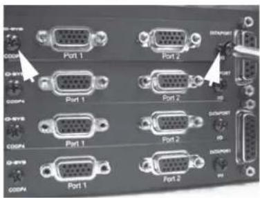
- Figure 12 -
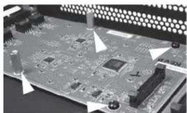
natural_image
Close-up of a computer motherboard with visible circuitry and connectors (no text or symbols)- Figure 13 -
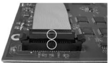
natural_image
Close-up of a computer motherboard with a central heat sink and two circular annotations highlighting the components (no readable text or symbols)- Figure 14 -

NOTE: When you connect the ribbon cable to the Core main board be sure that you connect it to the proper connector. The connectors on the Core main board are identified by the slot letters A through H.
-
When replacing the Blank Card with an I/O Card, the new ribbon cable must also be attached to the Core main board. To do this, locate the main board audio connectors. Then locate the appropriate card position indicator (Figure 15) on the main board for the card being replaced (A through H). Attach the ribbon cable in the same manner as the I/O Card, ensuring that the cable connector tab is aligned with the main board connector key and that the cable is properly seated with the ejector tabs in their locked position.
-
Replace the Core lid and secure the lid with the screws removed earlier.
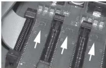
natural_image
Close-up of a computer motherboard with visible slots and connectors (no text or symbols)- Figure 15 -
Qualifi ed Ethernet Switches
Q-Sys uses layer 3 (DSCP) QoS. This type of QoS is deployed differently on different networks and therefore requires user intervention to set up properly. Because of this complexity, unmanaged switches are not acceptable for Q-Sys. For more details about network and switch setup, refer to the Help File in Q-Sys Designer. For more details about the following switches, refer to the manufacturers' website. The following switches have been tested and qualify for use with a Q-Sys™ network.

NOTE: Please visit qsc.com for a list of currently qualified switches.
Q-Sys™ GPIO Signal Specifications
GPIO Pin Assignments
DB15 Pin Signal Name Signal Type Description
| 1 RNO Relay Contact Relay - normally open | ||
| 2 RNC Relay Contact Relay - normally closed | ||
| 3 GPIO1 Normal Current GPIO pin | ||
| 4 GPIO3 Normal Current GPIO pin | ||
| 5 POWER Power +12 V DC | ||
| 6 GPIO5 High Current | GPIO pin - high current capable | |
| 7 GPIO7 High Current | GPIO pin - high current capable | |
| 8 GND | Ground | Ground |
| 9 RC | Relay Contact Relay - common | |
| 10 GND | Ground | Ground |
| 11 GPIO2 Normal Current GPIO pin | ||
| 12 GPIO4 Normal Current GPIO pin | ||
| 13 POWER Power | +12 V DC | |
| 14 GPIO6 High Current | GPIO pin - high current capable | |
| 15 GPIO8 High Current | GPIO pin - high current capable | |
GPIO Specifications
| Relay Pins | Normal Current Pins | High Current Pins |
| Maximum Voltage, relative to Ground: 30 V | Maximum Input Range: 0 V to 32 V | Maximum Input Range: 0 V to 32 V |
| Maximum Current through Relay: 1 Amp | Analog Input Range: 0 V to 24 V | Analog Input Range: 0 V to 24 V |
| Digital Input, Low: 0.8 V maximum | ||
| Power Pins | Digital Input, High: 2.0 V minimum | |
| Output Voltage: 11V min, 13V max | Digital Output, Low: 0.4 V maximum | |
| Maximum Output Current: 400 mA | Digital Output, High: 2.4 V minimum, 3.3 V maximum | |
| Digital Output Impedance: 1k ohm | ||
| High Current Output, Low: 0.4 V maximum | ||
| High Current Output, High: Not supported | High Current Output, High: 11 V minimum, 13 V maximum | |
| High Current Output, sink: 280 mAHigh Current Output, source: Not supported | High Current Output, sink or source: 280 mA |

NOTE: The maximum current sourced by one GPIO connector (including both High Current and Power Pins) is 400 mA.
Q-Sys Type 2 System Hardware Specifications
Core 500i Core 250i
| Description | System processor, control engine, and input and output device | System processor, control engine, and input and output device |
| Front Panel Controls LCD page forward momentary switch | Unit ID button momentary switchClear settings momentary switch | LCD page forward momentary switchUnit ID button momentary switchClear settings momentary switch |
| Front Panel Indicators Power On: Blue LED | Device Status: Tri-color LEDAudio Signal: Four tri-color LEDsCard Present Indicator: Bi-color LED behind Slot letters240 x 64 monochrome LCD graphics display | Power On: Blue LEDDevice Status: Tri-color LEDAudio Signal: Four tri-color LEDs /per I/O card slotCard Present Indicator: Bi-color LED behind Slot letters240 x 64 monochrome LCD graphics display |
| Rear Panel Connectors GPIO A: DA-15 (female 15-pin D shell connector) | GPIO B: DA-15 (female 15-pin D shell connector)Video Out DVI-DVideo Out: HD-15 (female 15-pin D shell connector)Video Out: HDMIRS-232: DE-9 (male 9-pin D shell connector)Power SwitchQ-Sys Network LAN A: RJ45 1000 Mbps onlyQ-Sys Network LAN B: RJ45 1000 Mbps onlyAUX ports: USB host x4AUX LAN port: RJ45 10/100/1000 MbpsAC Main Inlet - IEC male connector | GPIO A: DA-15 (female 15-pin D shell connector)GPIO B: DA-15 (female 15-pin D shell connector)Video Out DVI-DVideo Out: D-15 (female 15-pin D shell connector)RS-232: DE-9 (male 9-pin D shell connector)Power SwitchQ-Sys Network LAN A: RJ45 1000 Mbps onlyQ-Sys Network LAN B: RJ45 1000 Mbps / AUX LAN port: RJ45 10/100/1000 MbpsAUX ports: USB host x4AC Main Inlet - IEC male connector |
Maximum Ambient Operating Temperature 50°C (122°F). 40°C (104°F)
| Features and Options | ||
| Core Redundancy Yes Yes | ||
| Network Redundancy | Yes Yes | |
| Multi-Track Player (MTP) Options | Yes Yes | |
| Storage Options | Yes Yes | |
| PA Router | Yes Yes | |
| Core to Core Control Linking | Yes Yes | |
| Core to Core Paging | Yes No | |
| Core Capacity | ||
| Network Audio Channels | ||
| In | 128 | 64 |
| Out | 128 | 64 |
| In + Out (combined) | 128 | 64 |
| Local Analog I/O Channels^1,2 | ||
| In | 32 | 32 |
| Out | 32 | 32 |
| In + Out (combined) | 32 | 32 |
| Local Digital I/O Channels^1,2 | ||
| CobraNet In ^3 | 128 | 64 |
| CobraNet Out | 128 | 64 |
| AES In ^4 | 32 | 32 |
| AES Out | 32 | 32 |
| AES In + CobraNet In (combined) | 128 | 64 |
| AES Out + CobraNet Out (combined) | 128 | 64 |
| Acoustic Echo Canceling (AEC) Channels | 48 | 16 |
| Core to Core Network Channels | 128 | 16 |
| Line Voltage Requirements | 100 VAC - 240 VAC, 50 - 60 Hz | 100 VAC - 240 VAC, 50 - 60 Hz |
| Dimensions (HWD) | ||
| Chassis only (includes rack mount ears) | 3.5" x 19" x 16.13" (88.90 mm x 482.6 mm x 409.70 mm) | 3.5" x 19" x 16.13" (88.90 mm x 482.6 mm x 409.70 mm) |
| Chassis with front bezel | 3.5" x 19" x 16.76" (88.90 mm x 482.6 mm x 425.70 mm) | 3.5" x 19" x 16.76" (88.90 mm x 482.6 mm x 425.70 mm) |
Core 500i Core 250i
| Accessories Included 6 ft UL/CSA/IEC line cord •Rubber feet • User Manual • SoftwareCD • Optional audio I/O ship kit | 6 ft UL/CSA/IEC line cord •Rubber feet • User Manual • SoftwareCD • Optional audio I/O ship kit |
1 The maximum number of local channels a Core can have is 128 in and 128 out (64 in and 64 out). Each card has its own limitations (see the "I/O Cards (Mic/Line In, Line Out)" specifications). You can mix types, directions, and number of I/O channels; the combination dictates the maximum number of channels. For example, if you used all 4 channels of a Line In card, all input and output channels of 2 AES cards, you now have used 12 input channels, and 8 output channels, leaving 116 input channels, and 120 output channels to use with other cards.
2 Requires purchase of I/O cards.
3 Each CobraNet card has up to 32 input channels, and up to 32 output channels. You can reach 256 (128) CobraNet channels with 4 (2) cards or, up to 8 cards.
4 AES3 cards have four input channels, and four output channels per card.
I/O Cards (Mic/Line In, Line Out)
| Mic/Line Input CIML4 | High-Performance Mic/Line Input CIML4-HP Line Output COL4 | ||
| Description Four channels of microphone / line-level | analog audio input with 48V phantom power | Four channels of microphone / line-level analog audio input with 48V phantom power and high performance pre-amplifi ers and A/D converters | Four channels of balanced, line-level analog output |
| Performance | |||
| Dynamic Range Unweighted | >105 dB | >112 dB | >112 dB |
| Dynamic Range A-weighted | >108 dB | >115 dB | >115 dB |
| Distortion 20 Hz - 20 kHz +4 dBu (nominal input) | <0.009% THD+N | <0.004% THD+N | - |
| Distortion 20 Hz - 20 kHz 2 dB below clip (max) | <0.08% THD+N | <0.06% THD+N | <0.009% THD+N |
| Crosstalk 20 Hz - 20 kHz | |||
| Maximum | >90 dB | >90 dB | >75 dB |
| Typical | >110 dB | >110 dB | >110 dB |
| Frequency Response 20 Hz - 20 kHz (max) | ±0.5 dB | ±0.4 dB | ±0.4 dB |
| Frequency Response 20 Hz - 20 kHz (typ) | ±0.2 dB | ±0.2 dB | ±0.2 dB |
| Input Impedance | |||
| Balanced (nominal) | 10 k ohms | 10 k ohms | - |
| Unbalanced (nominal) | 10 k ohms | 10 k ohms | - |
| Common Mode Rejection 20 Hz - 20 kHz (max) | >40 dB | >47 dB | - |
| Common Mode Rejection 20 Hz - 20 kHz (typ) | >50 dB | >50 dB | - |
| Max Input Level 0.123, 2.25, 8.70, 17.35 Vrms | 1.23 mVrms to 17.35 Vrms | - | |
| -16, 10, 21, 27 dBu | -56 to 27 dBu | - | |
| -18.2, 7.04, 18.8, 24.78 dBv | -58.2 to 24.8 dBv | - | |
| (4 selections) | (continuously variable) | ||
| Mute Infi nite attenuation (via digital mute) Infi nite attenuation (via digital mute) Infi nite attenuation (via electromechanical relays) | |||
| Audio Converters | |||
| Analog to Digital Conversion (ADCs) | 24-bit delta-sigma at 48 kHz | 24-bit delta-sigma at 48 kHz | - |
| Digital to Analog Conversion (DACs) | - | - | 24-bit delta-sigma at 48 kHz |
| Group Delay | <13 Samples (≈271 μs) at 48 kHz | <13 Samples (≈271 μs) at 48 kHz | <10 Samples (≈196 μs) at 48 kHz |
| Connectors | Four 3-terminal Euro-style | Four 3-terminal Euro-style | Four 3-terminal Euro-style |
| User-confi gurable Options (software enabled) | |||
| Phantom Power | +48 V phantom power (IEC 1938 [1996]) | +48 V phantom power (IEC 1938 [1996]) | - |
| Output Trim | |||
| Vrms (max) | - | - | 8.7 V |
| dBu (max) | - | - | 21 dBu |
| dBv (max) | - | - | 18.8 dBv |
I/O Cards (DataPort Out, AES3)
DataPort Output CODP4 AES3 Input/Output CAES4
| Description Four audio output channels (2 DataPorts) for connection to DataPort equipped QSC amplifiers | Four input and four output channels of AES3 digital audio | |
| Performance | ||
| Dynamic Range Unweighted | >114 dB | >135 dB |
| Dynamic Range A-weighted | >117 dB | - |
| Distortion 20 Hz - 20 kHz +4 dBu (nominal input) | - | - |
| Distortion 20 Hz - 20 kHz 2 dB below clip (max) | <0.004% THD+N | - |
| Crosstalk 20 Hz - 20 kHz | ||
| Maximum | >75 dB | - |
| Typical | >100 dB | - |
| Frequency Response 20 Hz - 20 kHz (Maximum) | ±0.4 dB | ±0.4 dB |
| Frequency Response 20 Hz - 20 kHz (Typical) | ±0.2 dB | ±0.2 dB |
| Mute Infi nite attenuation (via electromechanical relays) Infi nite attenuation (via digital mute) | ||
| Audio Converters | ||
| Digital to Analog Conversion (DACs) 24-bit delta-sigma at 48 kHz - | ||
| Group Delay | <13 Samples (≈271 μs) at 48 kHz | Input with SRC enabled = <143 Samples (≈2.96 ms)Input without SRC enabled = 3 Samples (≈6.25 us)Output = 3 Samples (≈6.25 us) |
| Connectors Two 15-pin HD15 Four 3-terminal Euro-style | ||
| User-confi gurable Options (software enabled) | ||
| User-confi gurable Options (software enabled) | ||
| Amplifi er Standby Set amplifi er in standby mode - | ||
| Amplifi er Monitoring | Listen Button | |
| Mute Set individual channel mutes | - | |
| Meters | Peak or RMS Meter | - |
| Meter Selection | Amplifi er input level, load voltage, load current, load power and power headroom | - |
| Amplifi er Model Support CX, PowerLightTM 3 Series, DCA, and legacy VI models | - | |
1 Group Delay assumes that the sample rate converter is enabled.
CobraNet I/O Card (CCN32)
| Description | Up to 32 input and 32 output channels of CobraNet digital audio |
| Performance | |
| Dynamic Range A-weighted | >140 dB |
| Frequency Response 20 Hz - 20 kHz | ±0.2 dB |
| THD+N | -130 dB |
| Group Delay | Selectable:modeRate = 0x400: 1.479 mS(2.812 mS w/SRC enabled)modeRate = 0x500: 2.813 mS(4.146 mS w/SRC enabled)modeRate = 0x600: 5.479 mS(6.812 mS w/SRC enabled) |
| I/O Capacity | Selectable:4 x 4, 8 x 8, 16 x 16, 32 x 32 |
| Bundle Packing | 0 to 8 channels |
| CobraNet Network Transmitters | 16 |
| CobraNet Network Receivers | 16 |
| Configuration Management | Simple Network ManagementProtocol v1 |
| Mute | Infinite attenuation (via digital mute) |
| Connectors | Two RJ-45 jacks |

NOTE: Specifications subject to change without notice.
QSC™
Contact
Mailing Address
QSC Audio Products, LLC
1675 MacArthur Boulevard
Costa Mesa, CA 92626-1468 U.S.
Main Number
(714) 754-6175
World Wide Web
www.qscaudio.com
Sales & Marketing
Voice
(714) 957-7100 International
Toll free (U.S. only) (800) 854-4079
FAX
(714) 754-6174
info@qscaudio.com
Support
24/7 Support
QSC offers 24/7 support on Q-Sys™
Networked Audio Systems only.
Full Support for all QSC Products
Business Hours: 6 AM to 5 PM Pacifi c Time (Mon-Fri)
Tel. 800-772-2834 (U.S. only)
Tel. +1 (714) 957-7150
Fax. +1 (714) 754-6173
Q-Sys Emergency-only After-Hours and Weekend Support*
Tel: +1-888-252-4836 (U.S./Canada)
Tel: +1-949-791-7722 (non-U.S.)
* After hours calls are guaranteed a 30 minute response time from a
Q-Sys Support Team member. For Q-Sys ONLY!
qsyssupport@qscaudio.com
(An immediate e-mail response is not guaranteed. For URGENT issues use the phone numbers above.)
Q-Sys™ Customer Support
© 2012 QSC Audio Products, LLC. All rights reserved. QSC and the QSC logo are registered trademarks of QSC Audio Products, LLC in the U.S. Patent and Trademark office and other countries. Q-Sys and Intrinsic Correction are trademarks of QSC Audio Products, LLC. AMD is a trademark of Advanced Micro Devices, Inc. Cisco is a trademark of Cisco Systems, Inc. HP and ProCurve are trademarks of Hewlett Packard Development Company. Linksys is a trademark of Cisco Systems, Inc. CobraNet is a trademark of Cirrus Logic Microsoft trademarks are owned by Microsoft Corp. in the US and other countries. All other trademarks are the property of their respective owners. Patents pending.
- EXPLANATION OF TERMS AND SYMBOLS
- IMPORTANT SAFETY INSTRUCTIONS
- LITHIUM BATTERY WARNING
- FCC Statement
- Warranty (USA only; other countries, see your dealer or distributor)
- Disclaimer
- QSC Audio Products 3 Year Limited Warranty
- The QSC limited warranty is valid for a period of three (3) years from date of purchase in the United States and many (but not all) other countries.
- RoHS Statement
- Unpacking
- Mounting
- Rack Mount Instructions
- Connections
- AC Power Cord
- Q-Sys™ Network
- Mic/Line Inputs, Line Outputs, AES3 I/O
- DataPorts
- CobraNet
- Minimum System Requirements for Q-Sys™ Designer
- Software
- PC Hardware Requirements for Windows Vista Home Premium / Business / Ultimate/ Windows 7
- PC Hardware Requirements for Windows XP Professional
- Installing Q-Sys Designer
- Quick Start Guide
- Overview
- Type 2 Hardware
- Components
- QSC DataPort Amplifiers
- Loudspeakers
- Redundancy
- Network Redundancy
- Q-Sys Hardware Redundancy
- Q-Sys™ Core 250i | Core 500i | Panel Features
- Rear Panel Core 500i
- Q-Sys™ I/O Card Remove and Replace Procedure
- Tools
- Qualifi ed Ethernet Switches
- Q-Sys™ GPIO Signal Specifications
- GPIO Pin Assignments
- GPIO Specifications
- I/O Cards (DataPort Out, AES3)
- QSC™
- Contact
- Sales & Marketing
- Support
Brand : QSC
Model : Core 500i
Category : Processor