Core 1100 - Processor QSC - Free user manual and instructions
Find the device manual for free Core 1100 QSC in PDF.


| Product Type | System processor and control engine |
| Brand | QSC |
| Model | Core 1100 |
| Dimensions (H x W x D) | 7 x 19 x 17.875 inches (177.8 x 482.6 x 454 mm) |
| Net Weight (including I/O card) | 41 lb (18.6 kg) |
| AC Power Requirements | 100-240 VAC, 50-60 Hz |
| Typical AC Current Draw | 3.8 A @ 100 VAC |
| Maximum AC Current Draw | 8.5 A @ 100 VAC |
| Maximum Ambient Operating Temperature | 0°C to 50°C (32°F to 122°F) |
| Front Panel Display | 480 x 240 Color Graphics LCD |
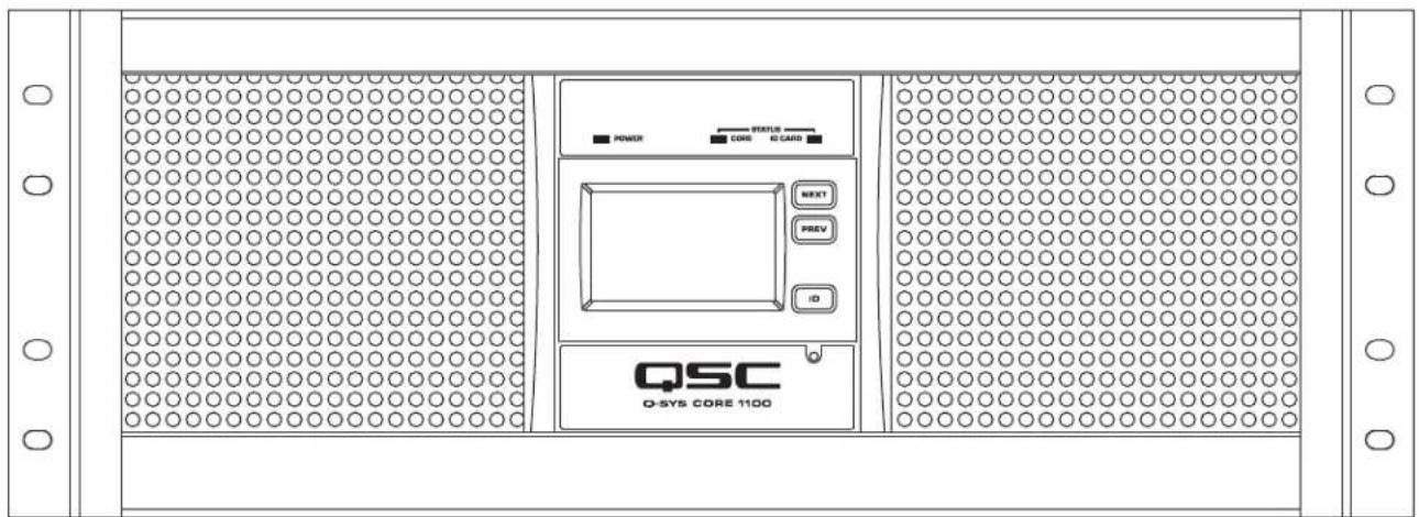
| Front Panel Controls | LCD Next/Prev, Unit ID, Clear Settings (paperclip) |
| Front Panel Indicators | Power On (Green), Core Status (Tri-color LED), I/O Card Status (Tri-color LED) |
| Rear Panel Connectors | RS-232 (DE-9 male), Video Out (HD-15 female), 2x AUX LAN (RJ45 10/100/1000), 4x USB Host (Type A), 2x GPIO (DA-15 female), 2x Q-LAN (RJ45 1000 Mbps) |
| Network Audio Channels In/Out | 256 x 256 |
| Network Audio Streams In/Out | 256 x 256 |
| Local I/O Capacity | 64 x 64 (with optional I/O card) |
| AEC Channels | 144 (100 ms tail length) |
| Core to Core Streaming | 256 x 256 |
| End Nodes | 256 Sources / 256 Destinations |
| GPIO Specifications | 8 GPIO pins (normal/high current), relay, +12V power |
| Included Accessories | 6 ft IEC line cord, Quick Start Guide, Warranty, optional I/O card kit |
| Maintenance | Clean with dry cloth only |
| Safety | Do not expose to rain/moisture, use grounded outlet |
| Service | Refer to qualified personnel, authorized QSC service |
| Warranty | Visit www.qsc.com for Limited Warranty |
Frequently Asked Questions - Core 1100 QSC
User questions about Core 1100 QSC
0 question about this device. Answer the ones you know or ask your own.
Ask a new question about this device
Download the instructions for your Processor in PDF format for free! Find your manual Core 1100 - QSC and take your electronic device back in hand. On this page are published all the documents necessary for the use of your device. Core 1100 by QSC.
USER MANUAL Core 1100 QSC
Core 1100 – Centralized Audio and Control Processor
Core 3100 – Centralized Audio and Control Processor
EXPLANATION OF TERMS AND SYMBOLS
The term "WARNING!" indicates instructions regarding personal safety. If the instructions are not followed the result may be bodily injury or death.
The term "CAUTION!" indicates instructions regarding possible damage to physical equipment. If these instructions are not followed, it may result in damage to the equipment that may not be covered under the warranty.
The term "IMPORTANT!" indicates instructions or information that are vital to the successful completion of the procedure.
The term "NOTE" is used to indicate additional useful information.

The intent of the lightning flash with arrowhead symbol in a triangle is to alert the user to the presence of un-insulated "dangerous" voltage within the product's enclosure that may be of sufficient magnitude to constitute a risk of electric shock to humans.

The intent of the exclamation point within an equilateral triangle is to alert the user to the presence of important safety, and operating and maintenance instructions in this manual.

IMPORTANT SAFETY INSTRUCTIONS


WARNING!: TO PREVENT FIRE OR ELECTRIC SHOCK, DO NOT EXPOSE THIS EQUIPMENT TO RAIN OR MOISTURE.
- Maximum ambient operating temperature is 50^ (122°F).
- Power requirements are: 100 – 240 VAC, 50 – 60 Hz, and the proper IEC power cord.
- Ensure reliable earth grounding is maintained.
-
Distribute the units evenly when installing in a rack. Hazardous conditions can be created by uneven weight distribution.
-
Read these instructions.
- Keep these instructions.
- Heed all warnings.
- Follow all instructions.
- Do not use this apparatus near water.
- Do not submerge the apparatus in water or liquids.
- Do not use any aerosol spray, cleaner, disinfectant or fumigant on, near or into the apparatus.
- Clean only with a dry cloth.
- Do not block any ventilation opening. Install in accordance with the manufacturer's instructions.
- Keep ventilation opening free of dust or other matter.
- Do not install near any heat sources such as radiators, heat registers, stoves, or other apparatus (including amplifiers) that produce heat.
- To reduce the risk of electrical shock, the power cord shall be connected to a mains socket outlet with a protective earthing connection.
- Do not defeat the safety purpose of the polarized or grounding-type plug. A polarized plug has two blades with one wider than the other. A grounding type plug has two blades and a third grounding prong. The wide blade or the third prong are provided for your safety. If the provided plug does not fit into your outlet, consult an electrician for replacement of the obsolete outlet.
- Protect the power cord from being walked on or pinched particularly at plugs, convenience receptacles, and the point where they exit from the apparatus.
- Do not unplug the unit by pulling on the cord, use the plug.
- Only use attachments/accessories specified by the manufacturer.
- Unplug this apparatus during lightning storms or when unused for long periods of time.
- Refer all servicing to qualified service personnel. Servicing is required when the apparatus has been damaged in any way, such as power-supply cord or plug is damaged, liquid has been spilled or objects have fallen into the apparatus, the apparatus has been exposed to rain or moisture, does not operate normally, or has been dropped.
- The appliance coupler, or the AC Mains plug, is the AC mains disconnect device and shall remain readily operable after installation.
- Adhere to all applicable, local codes.
- Consult a licensed, professional engineer when any doubt or questions arise regarding a physical equipment installation.
Maintenance and Repair

WARNING!: Advanced technology, e.g., the use of modern materials and powerful electronics, requires specially adapted maintenance and repair methods. To avoid a danger of subsequent damage to the apparatus, injuries to persons and/or the creation of additional safety hazards, all maintenance or repair work on the apparatus should be performed only by a QSC authorized service station or an authorized QSC International Distributor. QSC is not responsible for any injury, harm or related damages arising from any failure of the customer, owner or user of the apparatus to facilitate those repairs.
LITHIUM BATTERY WARNING
THIS EQUIPMENT MAY CONTAIN A NON-RECHARGEBLABE LITHIUM BATTERY. LITHIUM IS A CHEMICAL KNOWN TO THE STATE OF CALIFORNIA TO CAUSE CANCER OR BIRTH DEFECTS. THE NON-RECHARGEABLE LITHIUM BATTERY CONTAINED IN THIS EQUIPMENT MAY EXPLODE IF IT IS EXPOSED TO FIRE OR EXTREME HEAT. DO NOT SHORT CIRCUIT THE BATTERY. DO NOT ATTEMPT TO RECHARGE THE NON-RECHARGEABLE LITHIUM BATTERY.
FCC Statement

NOTE: This equipment has been tested and found to comply with the limits for a Class B digital device, pursuant to Part 15 of the FCC Rules.
These limits are designed to provide reasonable protection against harmful interference in a residential installation. This equipment generates, uses and can radiate radio frequency energy and, if not installed and used in accordance with the instructions, may cause harmful interference to radio communications. However, there is no guarantee that interference will not occur in a particular installation. If this equipment does cause harmful interference to radio or television reception, which can be determined by turning the equipment off and on, the user is encouraged to try to correct the interference by one or more of the following measures:
- Reorient or relocate the receiving antenna.
- Increase the separation between the equipment and receiver.
- Connect the equipment into an outlet on a circuit different from that to which the receiver is connected.
- Consult the dealer or an experienced radio/TV technician for help.
RoHS STATEMENT
The QSC Core 1100 and Core 3100 are in compliance with European Directive 2011/65/EU – Restriction of Hazardous Substances (RoHS2).
The QSC Core 1100 and Core 3100 are in compliance with "China RoHS" directives. The following chart is provided for product use in China and its territories:
| Q-SYS Core 1100 andand Core 3100 | ||||||
| 部件名称(Part Name) | 有害物质(Hazardous Substances) | |||||
| 铅(Pb) | 汞(Hg) | 镉(Cd) | 六价铬(Cr(vi)) | 多溴联苯(PBB) | 多溴二苯醚(PBDE) | |
| 电路板组件(PCB Assemblies) | X | O | O | O | O | |
| 机壳装配件(Chassis Assemblies) | X | O | O | O | O | |
| 本表格依据 SJ/T 11364 的规定编制。0:表示该有害物质在该部件所有均质材料中的含量均在 GB/T 26572 规定的限量要求以下。X:表示该有害物质至少在该部件的某一均质材料中的含量超出 GB/T 26572 规定的限量要求。(目前由于技术或经济的原因暂时无法实现替代或减量化。)This table is prepared following the requirement of SJ/T 11364.O: Indicates that the concentration of the substance in all homogeneous materials of the part is below the relevant threshold specified in GB/T 26572.X: Indicates that the concentration of the substance in at least one of all homogeneous materials of the part is above the relevant threshold specified in GB/T 26572.(Replacement and reduction of content cannot be achieved currently because of the technical or economic reason.) | ||||||
Warranty
For a copy of the QSC Limited Warranty, visit the QSC website at www.qsc.com
Unpacking
There are no special unpacking precautions. However, it is recommended that you keep the original packing materials for reuse in the rare event that service is required. If service is required and the original packing material is not available, ensure that the unit is adequately protected for shipment (use a strong box of appropriate size, sufficient packing/padding material to prevent load shifting or impact damage) or call QSC's Technical Services Group for replacement packing material and a carton.
What is included in your Q-SYS™ Core product carton:
• Q-SYS Core 1100 or Core 3100
• Quick Start Guide TD-000470
• QSC Limited Warranty
- IEC power cord
- Connector plug kit (provided with optional Q-SYS Audio I/O Cards requiring the kit.)
Mounting
Q-SYS products can be used in or out of an equipment rack. Rack mounting is optional. Rear rack ears are an available accessory if needed.
Rack Mount Instructions
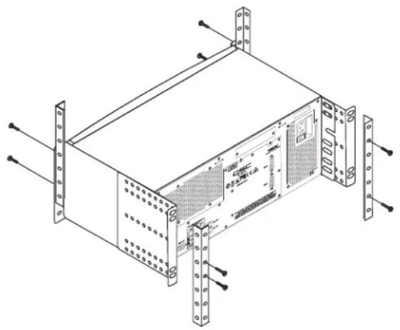
Rack mount the Q-SYS product by supporting it from underneath while aligning the front panel mounting holes (in the rack ears) with the threaded screw holes in the rack rails. Install all four front mounting screws and washers and tighten securely. All Q-SYS products come with rear rack support ears. Ensure that these rear mounting points are securely fastened to rear rack rails or side walls.

WARNING!: Reliable Earthing – Reliable earthing of rack-mounted equipment should be maintained. Particular attention should be given to supply connections other than direct connections to the branch circuit (e.g. use of power strips).
Mechanical Loading – Mounting of the equipment in the rack should be such that a hazardous condition is not achieved due to uneven or unstable mechanical loading.
natural_image
Technical line drawing of a server rack unit with mounting brackets and ventilation slots (no text or symbols)- Figure 1 -

CAUTION!: Elevated Operating Ambient - If installed in a closed or multi-unit rack assembly, the ambient operating temperature of the rack environment may be greater than room ambient. Consideration should be given to ensure that the maximum operating temperature range (0°C to 50°C (32°F to 122°F) is not exceeded.
Reduced Air Flow – Installation of the equipment in a rack should be such that the amount of air flow required for safe operation of the equipment is not compromised.
Circuit Overloading – Consideration should be given to the connection of the equipment to the supply circuit and the effect that overloading of the circuits might have on over-current protection and supply wiring.
Connections
AC Power Cord
Insert the AC power cord into the AC power inlet on the back of the Q-SYS product. Plug the other end into a 100 – 240V, 50 – 60 Hz AC outlet. If a different type of IEC power cord is required than that supplied with the product, contact QSC's Technical Services Group.
Q-SYS™ Network (Q-LAN)
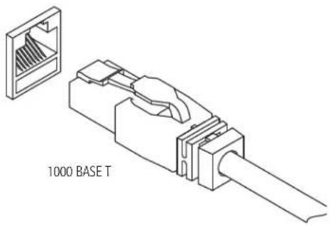
Connect one end of a data communications cable (CAT-5e rating or better) terminated with an RJ45 plug into the LAN A (and optionally LAN B) receptacle on the rear panel of the Q-SYS Core. Ensure that the lock tab on the cable engages with the RJ45 receptacle. (Figure 2)
- Figure 2 -

IMPORTANT: For detailed information about setting up the Q-LAN Network and Q-SYS Designer, refer to the Q-SYS Designer online help.
Q-SYS™ Core 1100 | Core 3100 Panel Features
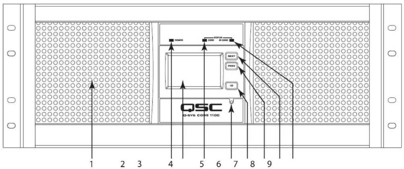
Figure 3 and Figure 4 show the Q-SYS Core front and rear panel features for a product having a simple configuration of one blank I/O Card slot.

NOTE: The Q-SYS hardware products are configured at the QSC factory per your order. At the time of order, you specify the type of Q-SYS Audio I/O Card to be installed in the Audio I/O bay on the Q-SYS Core.
Front Panel
-
Figure 3 -
-
Air Intake Vents
- Power-on LED
- 480 x 240 Color Graphics LCD
- Core Status LED
-
Clear Settings Paperclip Button (resets network properties)
-
ID Button (Identifi es Core in Q-Sys Designer GUI)
- LCD Previous Page Navigation Button
- LCD Next Page Navigation Button
- I/O Card Status LED
Rear Panel

-
Figure 4 -
-
RS-232 - DE-9 Male Connector for Serial Communications
- Core Exhaust Vents
- Video Out - HD-15 Female Connector Accepts Diagnostic VGA Monitor
- Auxiliary Port - USB Host Connectors (Type A) x 4
- Q-Sys Gigabit Network Ports (Q-LAN) - LAN A Primary, LAN B Backup
-
Auxiliary LAN Ports 10/100/1000 Mbps
-
Audio I/O Bay - Accepts Optional Q-Sys Audio I/O Card
- GPIO A and GPIO B - Female DA15 Connectors for Q-Sys Control I/O
- AC Mains Inlet - IEC Male Connector
- Power Switch
- Power Supply Exhaust Vents
Q-SYS™ GPIO Signal Specifications
GPIO Pin Assignments
| DB15 Pin | Signal Name | Signal Type | Description |
| 1 | RNO | Relay Contact | Relay - normally open |
| 2 | RNC | Relay Contact | Relay - normally closed |
| 3 | GPIO1 | Normal Current | GPIO pin |
| 4 | GPIO3 | Normal Current | GPIO pin |
| 5 | POWER Power | +12 V DC | |
| 6 | GPIO5 | High Current | GPIO pin - high current capable |
| 7 | GPIO7 | High Current | GPIO pin - high current capable |
| 8 | GND | Ground | Ground |
| 9 | RC | Relay Contact | Relay - common |
| 10 | GND | Ground | Ground |
| 11 | GPIO2 | Normal Current | GPIO pin |
| 12 | GPIO4 | Normal Current | GPIO pin |
| 13 | POWER | Power | +12 V DC |
| 14 | GPIO6 | High Current | GPIO pin - high current capable |
| 15 | GPIO8 | High Current | GPIO pin - high current capable |

- Figure 5 -
GPIO Specifications
| Relay Pins Maximum Voltage, relative to Ground | 30 V | |
| Maximum Current through Relay | 1 Amp | |
| Power Pins Output Voltage | 11 V min, 13 V max | |
| Maximum Output Current | 400 mA | |
| High Current Pins Maximum Input Range | 0 V to 32 V | |
| Analog Input Range: | 0 V to 24 V | |
| Digital Input, Low | 0.8 V maximum | |
| Digital Input, High | 2.0 V minimum | |
| Digital Output, Low | 0.4 V maximum | |
| Digital Output, High | 2.4 V minimum, 3.3 V maximum | |
| Digital Output Impedance | 1 k ohm | |
| High Current Output, Low | 0.4 V maximum | |
| High Current Output, High | 11 V minimum, 13 V maximum | |
| High Current Output, sink or source | 280 mA | |
All Power and High Current pins combined Maximum Source Current 400 mA
All GPIO Pins 1 through 8 combined Maximum Sink Current 1 A using 1 GND pin
2 A using 2 GND pins

NOTE: The maximum current sourced by one GPIO connector (including both High Current and Power Pins) is 400 mA.
GPIO Examples

flowchart
graph TD
    A["Normal or High Current Pin"] --> B["Ground"]
    B --> C["Arrow to Ground"]
    style A fill:#f9f,stroke:#333
    style B fill:#ccf,stroke:#333

flowchart
graph TD
    A["+12 V Pin"] --> B["Ground"]
    C["Normal or High Current Pin"] --> B
    D["Ground"] --> B
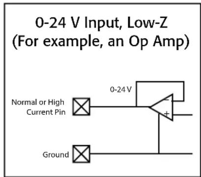
- Figure 6 -
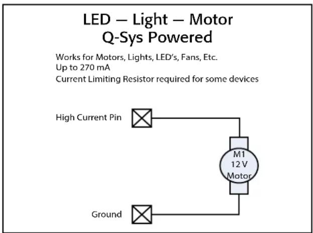

flowchart
graph TD
    A["Ground"] --> B["Normal or High Current Pin"]
    B --> C["M1 12V Motor"]
    C --> D["Power Supply"]
    D --> E["External 3.3-24V"]
    style A fill:#f9f,stroke:#333
    style B fill:#ccf,stroke:#333
    style C fill:#cfc,stroke:#333
    style D fill:#fcc,stroke:#333
    style E fill:#cff,stroke:#333
- Figure 7 -

- Figure 8 -
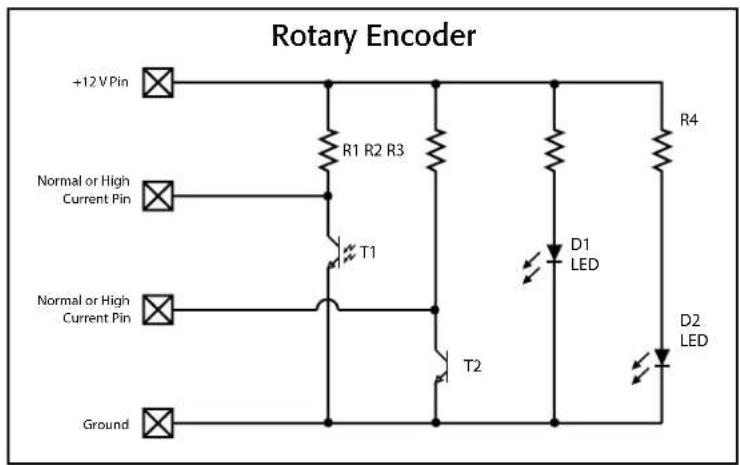
- Figure 9 -
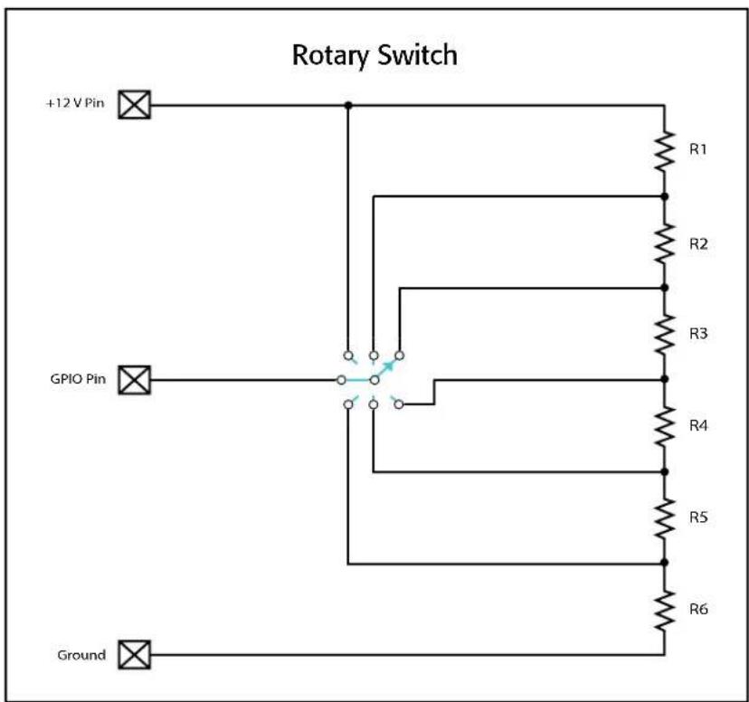
- Figure 10 -
Rotary Switch All resistors should have the same value. The total resistance should be about 10K Ohms. The individual resistor value should be 10,000 divided by the number of resistors. The schematic is an example only, and could easily be modified to have more switch positions or use multiple momentary buttons instead of a rotary switch.
Specifications
Core 1100 Core 3100
| Description System processor and control engine | ||
| Front Panel Controls LCD Next and Prev momentary buttonUnit ID momentary buttonClear settings momentary switch (use a paperclip or similar tool) | ||
| Front Panel Indicators Power On: Green LEDStatus:Core: Tri-color LEDIO Card: Tri-color LED480 x 240 Color Graphics LCD | ||
| Rear Panel Connectors RS-232: DE-9 (male 9-pin D shell connector)Video Out: HD-15 (female 15-pin D shell connector)Auxiliary ports AUX LAN A / AUX LAN B: RJ45 10/100/1000 MBpsAuxiliary USB host x4GPIO A / GPIO B: DA-15 (female 15-pin D shell connector)Q-SYS Network LAN A / LAN B: RJ45 1000 Mbps only | ||
| Maximum Ambient Operating Temperature 0°C to 50°C (32°F to 122°F) 0°C to 50°C (32°F to 122°F). | ||
| Capacity | ||
| Local I/O ^1 | 64 x 64 64 x 64 | |
| Network Audio Channels In/Out 256 x 256 512 x 512 | ||
| Network Audio Streams In/Out 256 x 256 256 x 256 | ||
| AEC (100 ms tail length) | 144 288 | |
| Core to Core Streaming | 256 x 256 512 x 512 | |
| End Nodes | 256 Destinations256 Sources | 256 Destinations256 Sources |
| Thermal - BTU / hour (typical) | 1100 | 1400 |
| Line Voltage Requirements | 100 VAC - 240 VAC, 50 - 60 Hz | 100 VAC - 240 VAC, 50 - 60 Hz |
| AC current draw (maximum) | 8.5 A @ 100 VAC | 8.5 A @ 100 VAC |
| AC current draw (typical) | 3.8 A @ 100 VAC | 4.4 A @ 100 VAC |
| Dimensions (HWD) | 7" x 19" x 17.875" (177.8 mm x 482.6 mm x 454 mm) | |
| Net Weight (including I/O card) | 41 lb (18.6 kg) | |
| Accessories Included | 6 ft UL/CSA/IEC line cord • Hardware Information Document • Warranty• Optional audio I/O ship kit | |
1 One I/O-card slot. Depends on I/O card purchased.
2 Using maximum fan-out with 16-channel unidirectional I/O Frames.
3 The CAES4 card (AES-3 input/output) doubles the audio channel count of any slot in which it is used.

NOTE: Specifications subject to change without notice.
QSC™
Mailing Address:
QSC, LLC
1675 MacArthur Boulevard
Costa Mesa, CA 92626-1468 U.S.
Main Number: (714) 754-6175
World Wide Web: www.qsc.com
Sales & Marketing:
Voice: (714) 957-7100 or toll free (U.S. only) (800) 854-4079
FAX: (714) 754-6174
E-mail: info@qscaudio.com
Q-SYS™ Customer Support
Application Engineering and Technical Services
Monday - Friday 7 AM to 5 PM PST (Excludes Holidays)
Tel. 800-772-2834 (U.S. only)
Tel. +1 (714) 957-7150
Q-SYS 24/7 Emergency Support\*
Tel: +1-888-252-4836 (U.S./Canada)
Tel: +1-949-791-7722 (non-U.S.)
24/7
Q-Sys™ Customer Support
*Q-SYS 24/7 Support is for Emergency assistance with Q-SYS systems only. 24/7 support guarantees a call back within 30 min after a message is left. Please include, Name, Company, Call Back Number and description of the Q-SYS emergency for prompt call back. If calling during business hours please use the standard support numbers above.
Q-SYS Support Email
qsyssupport@qsc.com
(Immediate email response times not guaranteed)
QSC
Technical Services
1675 MacArthur Blvd.
Costa Mesa, CA 92626 U.S.
Tel: 800-772-2834 (U.S. only)
Tel: +1 (714) 957-7150
FAX: +1 (714) 754-6173
- EXPLANATION OF TERMS AND SYMBOLS
- IMPORTANT SAFETY INSTRUCTIONS
- Maintenance and Repair
- LITHIUM BATTERY WARNING
- FCC Statement
- RoHS STATEMENT
- Warranty
- Unpacking
- Mounting
- Rack Mount Instructions
- Connections
- AC Power Cord
- Q-SYS™ Network (Q-LAN)
- Q-SYS™ Core 1100 | Core 3100 Panel Features
- Front Panel
- Q-SYS™ GPIO Signal Specifications
- Specifications
- QSC™
- Mailing Address:
- Sales & Marketing:
- Q-SYS™ Customer Support
- Application Engineering and Technical Services
- Q-SYS 24/7 Emergency Support\*
- Q-SYS Support Email
- QSC
Brand : QSC
Model : Core 1100
Category : Processor