RAVE 80s - Processor QSC - Free user manual and instructions
Find the device manual for free RAVE 80s QSC in PDF.


| Product Type | Digital Audio Processor / Network Bridge |
| Brand | QSC |
| Model | RAVE 80s |
| Form Factor | 1U Rackmount |
| Dimensions (W x H x D) | 19.0 x 1.75 x 6.0 inches (483 x 44 x 152 mm) |
| Weight | 5.0 lb (2.3 kg) |
| Power Supply | 100-240 V AC, 50/60 Hz, 20 W max |
| Network Audio Protocol | CobraNet |
| Audio Channels | 8 inputs / 8 outputs (digital) |
| Sample Rates | 48 kHz, 96 kHz |
| Bit Depth | 24-bit |
| Latency | 1.33 ms (at 48 kHz) |
| Network Connection | RJ-45 Ethernet (100Base-TX) |
| Control Interface | RS-232, GPIO |
| LED Indicators | Power, Network Activity, Audio Signal |
| Cooling | Fanless, convection cooled |
| Operating Temperature | 32 to 122 °F (0 to 50 °C) |
| Mounting | 19" rack ears included |
| Included Accessories | Power cord, quick start guide |
| Cleaning | Wipe with dry soft cloth; do not use liquids or solvents |
| Safety | Complies with UL, CE, FCC Class A |
| Spare Parts / Repairability | Contact QSC authorized service centers; no user-serviceable parts inside |
| Certifications | RoHS, WEEE |
Frequently Asked Questions - RAVE 80s QSC
User questions about RAVE 80s QSC
0 question about this device. Answer the ones you know or ask your own.
Ask a new question about this device
Download the instructions for your Processor in PDF format for free! Find your manual RAVE 80s - QSC and take your electronic device back in hand. On this page are published all the documents necessary for the use of your device. RAVE 80s by QSC.
USER MANUAL RAVE 80s QSC

RAVE
"S" series Digital Audio Router
USER MANUAL

▼ RAVE 80s (8 AES3 outputs)
▼ RAVE 81s (8 AES3 inputs)
▼ RAVE 88s (4 AES3 inputs + 4 AES3 outputs)
▼ RAVE 160s-24 (16 analog audio outputs)
▼ RAVE 161s-24 (16 analog audio inputs)
▼ RAVE 188s-24 (8 analog audio ins + 8 analog audio outs)
Attention!
• Maximum operating ambient temperature is 65^ C.
- Never restrict the airflow through the devices' fans or vents.
- When installing equipment into a rack, distribute the units evenly. Otherwise, hazardous conditions may be created by an uneven weight distribution.
- Connect the unit only to a properly rated supply circuit.
- Reliable Earthing (Grounding) of Rack-Mounted Equipment should be maintained.
EXPLANATION OF GRAPHICAL SYMBOLS

The lightning flash with arrowhead symbol, within an equilateral triangle, is intended to alert the user to the presence of uninsulated "dangerous voltage" within the product's enclosure that may be of sufficient magnitude to constitute a risk of electric shock to humans.
The exclamation point within an equilateral triangle is intended to alert the users to the presence of important operating and maintenance (servicing) instructions in the literature accompanying the product.
EXPLICATION DES SYMBOLES GRAPHIQUES

CAUTION: To reduce the risk of electric shock, do not remove the cover. No user-serviceable parts inside. Refer servicing to qualified service personnel.
WARNING: To prevent fire or electric shock, do not expose this equipment to rain or moisture.

AVIS
RISQUE DE CHOC ÉLECTRIQUE NE PAS OUVRIR

Electrical energy can perform many useful functions. This unit has been engineered and manufactured to assure your personal safety. Improper use can result in potential electrical shock or fire hazards. In order not to defeat the safeguards, observe the following instructions for its installation, use and servicing.
PRECAUTIONS
FEDERAL COMMUNICATIONS COMMISSION (FCC)
INFORMATION
NOTE: This equipment has been tested and found to comply with the limits for a Class A digital device, pursuant to Part 15 of the FCC Rules. These limits are designed to provide reasonable protection against harmful interference in a commercial installation. This equipment generates, uses, and can radiate radio frequency energy and, if not installed and used in accordance with the instructions, may cause harmful interference to radio communications. Operation of this equipment in a residential area is likely to cause harmful interference, in which case the user will be required to correct the interference at his or her own expense.
RAVE "S" Series Digital Audio Router User Manual
Warning Notices 2
Introduction 4
Illustration of RAVE unit 5
Glossary 6
How it works 8
Channel routing 10
Installation 11
Pre-Installation preparation: analog signal levels (RAVE 160/161/188s only) .... 11
Rack mounting 13
Connections 13
Ethernet connection 13
Analog audio connections (RAVE 160/161/188 only) 14
Digital audio connections (RAVE 80/81/88 only)....15
AC power 16
Master/Sync output 16
Slave/Sync input 16
RS-232 port 17
Synchronizing to an AES3 (AES/EBU) stream....18
Operation 20
Network activity/status indicators 20
Channel audio signal indicators 22
Program and software "kill" mode 24
Routing 24
Network Design Considerations 26
Specifications 29
Appendix 32
Ethernet Cabling 32
RS-232 Port Information 32
Resources 33
How to contact QSC Audio Products and Warranty Information.... 34
Note: Page numbering starts with cover as page 1. This is done to keep electronically-distributed document page numbering synchronized with the printed document.
RAVE™ Digital Audio Router products provide a means of transporting CobraNet™ audio signals over a Fast Ethernet network. Using standard network hardware and physical media, a RAVE system has a maximum capacity of 64 audio channels on a 100BASE-TX repeater segment and the ability to support hundreds of audio channels on a switched Ethernet LAN. RAVE transports the audio signals over the network in a standard uncompressed 48 kHz digital format in resolutions of 16, 20 or 24-bit. Additionally, RAVE products support operation in stand-alone mode, requiring minimal front-panel setup, or in software mode, utilizing off-the-shelf applications implementing the Simple Network Management Protocol, or SNMP.
A RAVE system handles routing in bundles of up to 8 individual audio channels. Each RAVE supports up to two bundles of audio. The availability of audio through network transmission or reception is dependent on the RAVE model. The 88s
and 188s-24 can both receive and transmit data over the network and can support higher capacity configurations when setup through the Management Interface using SNMP.
Each RAVE unit has a female RJ-45 Ethernet connector on its rear panel for connecting to a standard Category 5 Unshielded Twisted Pair (UTP) cable. For economy and flexibility, RAVE utilizes standard off-the-shelf Fast Ethernet devices such as repeaters, switches and fiber optic media converters. You need at least two RAVE devices—one to send and one to receive, or two that operate bi-directionally—to route audio over an Ethernet network. There are currently six RAVE models, with three basic send/receive configurations (16 channels send, 16 channels receive, or 8 channels send/8 channels receive). Each of these configurations is available with either analog or digital AES3 (often called AES/EBU) audio inputs and outputs. The six models are listed in the table below:
| MODEL | AUDIO CHANNELS AVAILABLE | NETWORK BUNDLE USAGE | |||
| AUDIO INPUTS | AUDIO OUTPUTS | RECEIVED | TRANSMITTED | ||
| DIGITAL I/O | RAVE 80s | none | 16 ch. (AES3 x 8) | 2 Bundle Assignments | none |
| RAVE 81s | 16 ch. (AES3 x 8) | none | none | 2 Bundle Assignments | |
| RAVE 88s | 8 ch. (AES3 x 4) | 8 ch. (AES3 x 4) | 1 Bundle Assignment | 1 Bundle Assignment | |
| ANALOG I/O | RAVE 160s-24 | none | 16 ch. (Analog) | 2 Bundle Assignments | none |
| RAVE 161s-24 | 16 ch. (Analog) | none | none | 2 Bundle Assignments | |
| RAVE 188s-24 | 8 ch. (Analog) | 8 ch. (Analog) | 1 Bundle Assignment | 1 Bundle Assignment | |

NOTE! Many instances of RAVE model numbers, as presented in this manual, have had the suffix ("s" or "s-24") removed for clarity and ease of reading.
Front view of a RAVE 161s-24; other models are similar

Rear view, from top:
RAVE 160s-24, RAVE 188s-24, RAVE 161s-24, RAVE 80s, RAVE 88s and RAVE 81s

AES3— A digital audio format specification approved by the Audio Engineering Society and European Broadcast Union for inter-device conveyance of a dual-channel (stereo) digital audio signal. Also called AES/EBU. This specification is periodically revised and amendments are published by the AES.
Bundle—The basic network transmission unit under CobraNet. Up to 8 audio channels may be carried in a bundle. Each bundle is assigned a unique number and its value denotes the distribution type, either multicast or unicast, between RAVE devices. A bundle can be thought of as a virtual cable between two or more RAVE devices, which transports multiple audio channels. Bundle numbers can be assigned to the RAVE via its front-panel interface or through an SNMP supporting browser or related application.
Channel—A single digital audio signal. Audio channels on CobraNet have a 48 kHz sampling rate and may be of 16, 20 or 24-bit resolution. Up to 8 audio channels may be carried in a bundle.
Conductor—The CobraNet device on the network which supplies the master clock and permissions list. A conductor arbitration procedure insures that there is one and only one conductor per network at any time.
Crossover cable—An Ethernet patch cable with the transmit and receive wire pairs swapped at one end. Crossover cables permit a direct connection of two nodes without a repeater or switch in between. A crossover cable can also be used for cascading repeaters or switches that don't have an available uplink port.
Latency—The time interval from when an event occurs and when it is perceived. In digital audio routing, this is typically the time required to convert an analog input to a digital signal, transmit that signal over the network, receive it and convert it back to analog for the end listening device. Latency is dependant upon every device in the signal chain that adds any time delay to the delivery of the audio.
Management Interface—The management interface (MI) can be thought of as the software and front panel controls that determine how the RAVE will operate. The MI is the means for control and monitoring of CobraNet parameters within the RAVE unit. Two main management methods are supported by CobraNet; the host management interface (HMI) and SNMP. RAVE supports SNMP and its front panel switches for control. A RAVE unit can use its front-panel thumbwheel switches to access most configuration parameters for stand-alone mode. The front-panel interface will satisfy most configuration requirements. All of RAVE's configuration parameters are accessible using SNMP.
MI Variable Set— The MI variable set is the group of parameters that can be controlled by the MI.
Multicast Bundle—A multicast bundle supports a one-to-many routing of audio on the network. Ethernet multicast addressing is used to deliver a multicast bundle. Because a multicast bundle consumes bandwidth network-wide (within the same broadcast domain), use of this delivery service must be rationed on a switched network. By design, all bundles on a repeater network are of the multicast type.
Repeater—Network repeaters are commonly referred to as Ethernet multi-port hubs. A data signal arriving in any port is reproduced out all other ports on the hub. A repeater hub does not buffer or interpret the data passing through it. An Ethernet network is typically wired in a star configuration and the repeater hub is at the center. Repeaters are half-duplex by design and all RAVEs attached to a repeater share the same broadcast domain. 64 audio channels is the maximum capacity on a LAN configured with network repeaters. Repeater networks with RAVE require the use of Class II devices that are 100 Mbps only.
Note: CobraNet networks must consist of only network repeaters or only network switches. A mix of these devices is not supported on the same LAN. This does not apply to non-CobraNet™ traffic.
Simple Network Management Protocol—SNMP is the network industry's standard for control and monitoring of network devices. SNMP is a cross-platform, cross-network protocol and may be used as the interface for managed network switches and multi-protocol routers. CobraNet supports SNMP as one method for accessing its Management Interface.
Stand Alone Mode— Stand alone mode is operating a RAVE using the RAVE's front and rear panel controls. All available management interface variables are accessed using the front panel hexadecimal switches when operating in stand alone mode. Also called hardware mode. Redundancy and external Synch can be setup via SNMP independent of the front panel switch positions.
Software Mode— Software mode is operating a RAVE using the SNMP software only. All available management interface variables are accessed through the network connection using a PC and the proper software.
Switch—A network switch examines incoming data and sends it to the port or ports to which the data is addressed. Networks that use switches realize higher overall bandwidth capacity because data may be received through multiple ports simultaneously without conflict. Switches are full-duplex devices. A network that uses switches to connect network segments is called a switched network. Because each switch port has its own collision management and full use of bandwidth, audio capacity may realistically reach several hundred channels depending on the network architecture. Additionally, switched networks may support non-CobraNet packet types, allowing control and monitoring of the system devices (QSControl, SNMP). Network switches range from basic stand-alone models to more complex management and routing devices.
Note: CobraNet networks must consist of only network repeaters or only network switches. A mix of these devices is not supported on the same LAN. This does not apply to non-CobraNet traffic.
Unicast Bundle— Unicast bundles provide a single point-to-point connection between two devices. Unicast transmission is the preferred choice when operating on network switches. Data which is unicast is addressed to a specific RAVE or other CobraNet device. A network switch may examine the unicast address field of the data and determine on which port the addressed RAVE resides and direct the data out only that port. Unicast bundles conserve bandwidth network wide and reduce congestion at the node.
Uplink port—A special port on a network repeater or switch used for cascading or linking to another repeater or switch.
Ethernet networks are used most often for data communications, such as with file or print sharing on an office LAN (Local Area Network). A typical application might include a number of PCs or workstations, servers and shared printers all connected to common Ethernet hardware. Messages (Ethernet frames) are communicated between devices on the LAN in a random and non-deterministic manor. Network response to print messages or file access is usually noncritical so long as the intended outcome occurs in a reasonable amount of time. For example, when multiple users are attempting to share a common printer at the same time, some users will likely experience delays in output. Collisions or failed attempts to access the network may also be acceptable so long as the intended messages are retransmitted. Most often, a limited amount of collisions are expected and are usually transparent to the user.
Audio networks are different because late arrival or failed attempts to transmit audio messages are immediately perceived by the listener. Therefore, audio network transmission must be error free with low latency and delivery must be precisely defined. To do this, RAVE incorporates the CobraNet protocol. CobraNet is the industry's most reliable audio delivery mechanism. CobraNet provides low latency, deterministic delivery of audio over Ethernet on either network repeaters or switches. Collisions are prevented on shared media links, such as repeater hubs, by CobraNet's proprietary "order persistent" media access scheme. On dedicated media links, such as with network switches, collisions are prevented due to separate transmit and receive paths in a full-duplex con-
nection and/or an abundance of bandwidth dedicated to a single device on each switch port. On network switches, RAVE establishes a half-duplex link to a dedicated port. The 100 Mbps of bandwidth available at a switched port is more than enough to support all of the typical communications requirements of RAVE while providing for an ample amount of control and monitoring through the MI via SNMP messages.
A network of CobraNet devices can be thought of as a synchronized orchestra. The unit acting in the "conductor" role provides the system clock and grants network permissions to the "performer" units. Each RAVE has a local internal clock so that any RAVE may arbitrate for the role of network "conductor". RAVE devices may also be synchronized to an external clock source, which is attached to a rear-panel BNC connector. External synchronization requires configuration setup through the front-panel interface or via SNMP. The permissions list is a message sent with the system clock that allow individual units access to the network and reserve bundle assignments.
RAVE routes audio in bundles that are populated with a default value of 8 channels per bundle. The actual number of channels per bundle may be altered, from 0 to 8, from the management interface using SNMP. Reducing channel count reduces system bandwidth requirements. On the models supporting CobraNet transmission (81/88/161/188) audio is brought into the RAVE using the rear panel connectors.
Introduction: How It Works (continued)
In default mode, the signals from the first 8 audio channel inputs will be grouped together in a bundle whose "network identifier" number is specified from the front-panel hexadecimal switches or through the management interface. The bundle will then be sent over the network to the destination devices that are configured, or set to receive the bundle. RAVE models supporting CobraNet reception (80/88/160/188) can then receive the bundle by setting their respective front-panel hexadecimal switches (or MI variables) to the appropriate bundle number. The received bundle is then separated into individual audio channels and forwarded to the first 8 audio outputs at the rear-panel in either analog or digital format, depending upon which model Rave is used.
Signal flow for the six RAVE models are depicted below. The wide black arrows indicate the bundle direction to or from the network interface, while the thin arrows indicate individual audio channels to or from RAVE's rear-panel connectors.

RAVE 80s: 8 AES Outs
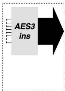
RAVE 81s: 8 AES ins
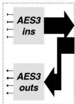
flowchart
graph TD
    A["AES3 ins"] --> B
    C["AES3 outs"] --> B
RAVE 88s: 4 AES ins + 4 AES outs

RAVE 160s-24: 16 analog outs

RAVE 161s-24: 16 analog ins

flowchart
graph TD
    A["ADCs"] --> B["DACs"]
    B --> C["Data Flow Left"]
    B --> D["Data Flow Right"]
RAVE 188s-24: 8 analog ins + 8 analog outs
Introduction: Channel Routing
Channel Routing
A RAVE network handles routing in bundles of up to eight audio channels. Each bundle of audio transmitted on the network occupies a unique identifier, or number. In stand-alone mode, each RAVE device handles two bundles—two sent, two received, or one of each. For example, a RAVE 161, with 16 analog audio inputs, supports two bundles for transmission over the network. Therefore, the 161 requires two separate bundle number assignments to enable both groups of audio to be sent onto the network. In default mode, one bundle comprises audio channels 1 through 8—the second bundle, channels 9 through 16. You can always alter the number and order of audio channels within each bundle via SNMP.
Similarly, a RAVE 80, with eight AES3 digital outputs, supports network reception of two bundles (each AES3 output carries two audio channels). With receivers, each bundle number need not be unique. A receiver may "tune-in" to two specific bundles from two separate transmitters or both receiving bundle assignments may be the same. Whether the bundle assignments on a receiver (or multiple receivers) can be duplicated is dependent on whether the particular transmitters are setup for unicast or multicast transmission. On network repeaters, all bundles are multicast. On network switches, the value of the bundle assignment determines the addressing of the transmission.
A RAVE device that both sends and receives, such as the RAVE 188 (eight analog inputs and 8 analog outputs) or RAVE 88 (4 AES3 inputs and 4 AES3 outputs), transmits one bundle and can receive another. Note: in software mode, the RAVE 88 and 188 can support two bundles in each direction.
Behind a removable cover on the front panel of each RAVE unit are four hexadecimal rotary switches. In stand-alone (hardware) mode, these switches are used for selecting the assignments for each of RAVE's two bundles. In software mode, these switches are used to provide a network name for the RAVE.

Bundle Setup:
The two left-most switches set the assignment of the RAVE's first bundle. The default mapping for the first bundle is:
RAVE 81/88/161 and 188- bundle 1 transmitted onto network from audio inputs 1 through 8
RAVE 80 and 160- bundle 1 received from network routes to audio outputs 1 through 8
The two right-most switches set the assignment of the device's second bundle. The default mapping for the second bundle is:
RAVE 81 and 161- bundle 2 transmitted onto network from audio inputs 9 through 16
RAVE 88 and 188- bundle 2 received from network routes to audio outputs 1 through 8
RAVE 80 and 160- bundle 2 received from network routes to audio outputs 9 through 16
NOTE! Detailed instructions on setting network bundle assignments follow later in the Operation chapter.
PRE-INSTALLATION PREPARATION: ANALOG AUDIO SIGNAL LEVELS (RAVE 160/161/188 ONLY)
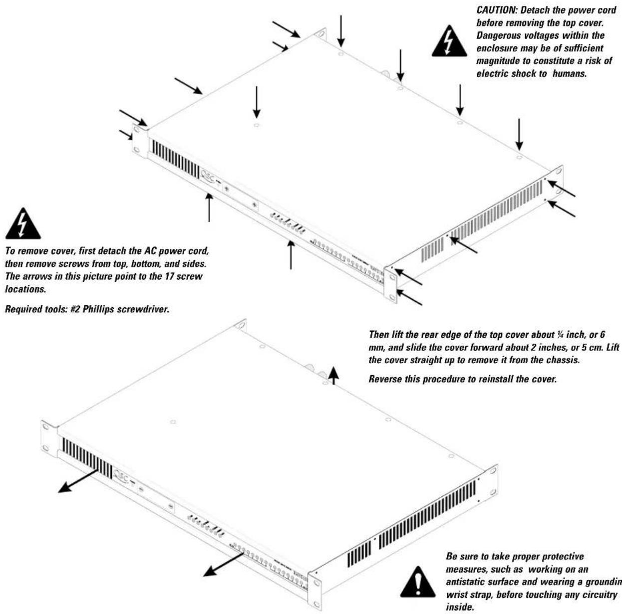
The RAVE models supporting analog audio inputs and/or outputs may require signal level setup to achieve optimum performance. Level setup must be configured before rack-mounting the units. The digital AES3 (digital audio) models do not require any adjustment. Level adjustments are made by configuring internal jumpers on the main circuit board. For access to these jumpers, you must first remove the top cover of the RAVE unit as follows.
NOTE: If synchronizing to an AES3 (AES/EBU) source, see page 18 for AES3 jumper settings.
Input Level Sensitivity (RAVE 161s-24 and 188s-24 only)
Input level sensitivity is the RMS analog signal level at which a sinusoidal waveform will produce a digital full scale signal in the device. The available settings are +24dBu, +18dBu, and +12 dBu (reference: 0 dBu = 0.775 volt), which are 12.3, 6.1, and 3.1 volts rms, respectively. These correspond to 17.4, 8.7, and 4.4 volts peak. Check the specifications of the audio equipment driving the inputs to determine the correct setting. Each channel's sensitivity is independent of the others and must be set individually.
- First, locate the input sensitivity-selection jumper headers, which are in a row of small groups of pins (6 in each group) on the topside of the circuit board, somewhat midway between the front edge of the board and the rear edge. You'll see a row of 16 headers on a RAVE 161, or eight on a RAVE 188—one for each input channel.
- Determine what the correct setting should be for each channel, and set the jumpers as shown in the illustration. There is also a legend printed on the circuit board showing the jumper setting options. Save any unused jumpers for future use.


front of unit ↓
Output Levels (RAVE 160s-24 and 188s-24 only)
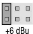
The output level setting determines the absolute RMS level of an analog signal produced by a digital full scale signal representing a sinusoidal waveform. The four selections available are +24dBu, +18dBu, +12dBu, and +6dBu (reference: 0 dBu = 0.775 volt)—12.3 volts, 6.1 volts, 3.1 volts, and 1.5 volts rms, respectively. These voltages respectively correspond to 17.4, 8.7, 4.4, and 2.2 volts peak.
- As with setting the input level, the output level for each channel is set by arranging jumpers on the pins of a header. These headers are located near the rear edge of the circuit board, and there is one header for each analog output: eight in the RAVE 188, and 16 in the RAVE 160.
- Place jumpers as required for the desired output level as shown in this illustration. A legend printed on the circuit board also shows the jumper settings. Save any unused jumpers for future use.


front of unit
RACK MOUNTING (ALL MODELS)
A RAVE unit is 1 RU (1 rack space) high and mounts in any standard 19-inch wide equipment rack. The top cover of the chassis must be in place and properly secured with screws before you can mount the RAVE unit.
- Rack mounting is optional.
- Use four mounting screws to fasten the front ears of the RAVE unit to the mounting rails of the rack.
- The chassis of a RAVE unit also has mounting ears on its rear corners. If used for mobile, portable, touring or other high vibration application, support each RAVE at the rear ears as well. If you have several units stacked in the rack, support the bottom one at the rear corners.
- Dress and support any cables that are to attach to the RAVE unit so that their weight doesn't put an undue strain on their connectors. Do not pinch or otherwise crush CAT-5 Ethernet cable.

Be careful when installing the unit in an equipment rack; its cooling vents must not be obstructed.
Connections: 100BASE-TX Ethernet
ETHERNET CONNECTION (ALL MODELS)
A female modular RJ-45 jack on the rear panel is for connecting the RAVE unit to a 100BASE-TX Ethernet device.

- To connect the network cable to the RAVE unit, insert the RJ-45 male connector—with its locking tab facing down (the only way the connector will fit into the jack)—until the tab clicks into place, just like connecting a modular telephone cable to a telephone.
- To disconnect the network cable from the RAVE unit, grasp the connector and squeeze up on the locking tab, then pull it out of the RJ-45 jack.
A 100BASE-TX network connection requires CAT-5 UTP (unshielded twisted pair) grade cable. Suitable Ethernet cable is readily available at most computer suppliers. To make your own, see the Appendix for connector pinouts and for cable manufacturers.
ANALOG AUDIO CONNECTIONS
The analog RAVE models (RAVE 160 /161 and 188) use normal analog balanced audio inputs and outputs, with three terminals per channel: Hi (+), Lo (-) and Shield..
Analog audio inputs and outputs connect using detachable terminal strip headers on the rear panel of the RAVE unit. These detachable headers allow for pre-wiring of racks and quick connecting and disconnecting for installation, removal, reconfiguration, or replacement. The detachable headers connect to and disconnect from the pins simply by pushing on and pulling off. The illustration at right shows how the detachable headers work.
To connect a wire to a terminal:
- Strip back the insulation on the wire about 14 inch (approximately 6.3 mm).
- Loosen the screw above the header terminal, then insert the wire fully.
- Tighten the screw until the wire is firmly anchored. Do not overtighten.
- Use a wire tie to secure the cable to the grip of the header block.
To connect balanced inputs: insert the +, -, and shield into the header as shown at the right.
To connect unbalanced inputs: insert the signal conductor into the + terminal and the shield to the - terminal, with a jumper to the ground/shield terminal, as shown at the lower right.


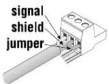
Analog audio connections- RAVE 161s-24 shown

Channel numbers and connector pinouts are labeled on the rear of the unit, as shown in the illustration above. The actual channel assignment depends on the model.
RAVE 188: 16 analog channels; 8 inputs, labeled 1 through 8 and 8 outputs, labeled 1 through 8
RAVE 161: 16 analog audio input channels labeled 1 through 16
RAVE 160 : 16 analog audio output channels labeled 1 through 16 on the rear of the unit.
DIGITAL AUDIO CONNECTIONS
The digital RAVE models (RAVE 80/81/88) use the AES3 (also known as AES/EBU) digital audio standard. Each AES3 XLR jack carries 2 channels of digital audio, each carrying between 16- and 24 bits per sample.
All digital audio I/O on a RAVE unit are terminated in accordance with the AES3 specification. AES3-1992 warns against the use of more than 1 receiver across the cable. If you need to supply the same AES3 signal to more than one receiving device, you will need a suitable digital distribution amplifier. AES3 inputs automatically and independently perform digital sample rate conversion. This allows any source device to run asynchronously to the network and to other sourcing devices.
Each AES3 input or output carries a pair of digital audio channels through a balanced 3-pin XLR connector. Like analog equipment, outputs use connectors with male pins and inputs use connectors with female pins. Unlike analog equipment, AES3 cables must use 110 ohm digital audio cable. The connector's Pin 1 is used for the cable shield and the signal ground. Pins 2 and 3 are for the digital audio signals.


Use 110 ohm AES/EBU digital audio cables for digital audio connections
To construct an AES3 digital audio cable: use 110 ohm digital audio cable; terminate using XLR connectors per the pinout provided to the right.

Channel numbers and connector pinouts are labeled on the rear of the unit, as shown in the illustration above. The actual channel assignment depends on the model.
RAVE 88 : 8 digital AES3 channels (16 audio channels): 4 inputs and 4 outputs labeled 1-2, 3-4, 5-6 and 7-8
RAVE 81 : 8 digital AES3 input channels (16 audio channels) labeled 1-2 through 15-16 on the rear of the unit.
RAVE 80: 8 digital AES3 output channels (16 audio channels) labeled 1-2 through 15-16 on the rear of the unit.
Connections: AC Power and Fuses, Master/Sync Output and Slave/Sync Input
AC POWER:
- The detachable AC power cord connects to the RAVE at the rear-panel IEC connector.
- There is no power switch; the AC disconnect device is the detachable power cord.
• A RAVE operates on line voltages from 100 to 240 VAC, 50 to 60 Hz. No user setting is required.
FUSES:
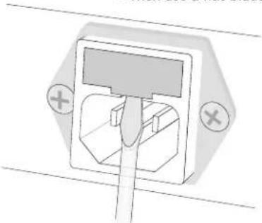
• The fuse holder is an integral part of the IEC connector and contains two fuses.
- To replace a fuse, first detach the AC power cord from the RAVE unit.
- Then use a flat-blade screwdriver to pry the fuse holder out, as shown below, left.
natural_image
Pure electrical outlet diagram without any text, numbers, or symbols
Replace only with the same type fuse.
Use only a power source with a protective earth ground.
The fuses are held in the round openings in the end of the fuse holder as shown at right. Replace one or both fuses with the same type: 20 × 5 mm, 2 amp, 250V.

natural_image
Mechanical assembly diagram showing a piston and connecting rod with arrows indicating force direction (no text or labels)2A 250V 20 x 5 mm FUSE (2 required)
MASTER/SYNC OUTPUT
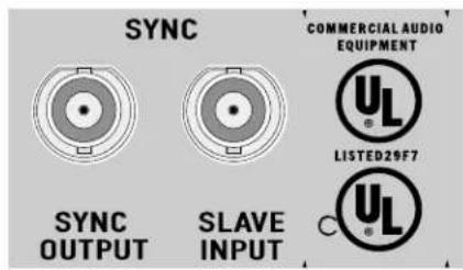
A 5 Vp-p sample rate clock is output this 50 ohm BNC female jack whenever the unit is connected to the network and is operating properly. This clock output can be used to synchronize external digital audio or video equipment, and is synchronous with the clock signal broadcast over the network. No clock signal is produced if the unit loses power, its Ethernet connection, or if a severe fault occurs with the unit. In the event of severe fault within the RAVE unit, the front panel Fault LED will illuminate.
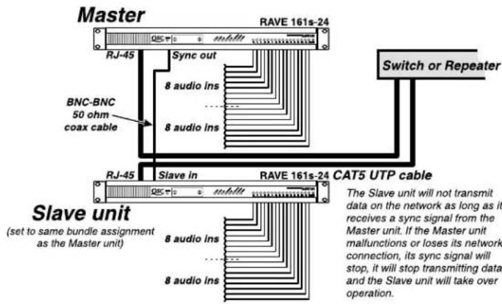
How to use for Redundant Operation: Connect the SYNC OUTPUT to the slave unit's SLAVE INPUT. The loss of this signal to the slave initiates a fail-over event and the slaved unit becomes active. Redundant operation provides a second RAVE for audio backup in mission-critical applications.
Sync connections on the rear panel of a RAVE unit
SLAVE/SYNC INPUT
This 50 ohm BNC female jack can be used to synchronize the network to an external clock source. The unit must be acting as the system "conductor" and the external clock must be a valid increment of the isochronous cycle clock. This cycle is currently fixed at 750Hz . The valid external clock range is from 15kHz to 49.5kHz . To implement external synchronization, the first group of front panel hexadecimal switches must be set between "80" and "FE". This provides well over 100 bundle assignments possible for use with the external synchronization feature. As with all managed features, external synchronization can be configured through the management interface using a software application implementing SNMP.
How to use for Redundant Operation: SLAVE INPUT is connected to master (main) unit's SYNC OUTPUT. During redundant operation, the slave input provides the backup unit with a sample clock from the primary or master RAVE. As long as this signal is present, the slave unit will exist on the network in standby mode. In standby, all network audio communication is suspended and output relays are forced open. If the master clock is lost, the slave senses the missing clock on its slave input and commences network audio communication. The slave unit becomes enabled when the sample clock is missing from its SLAVE INPUT.
Rear panel coax cable and Ethernet connections

Configuration example for redundant audio transmission
Note that audio connections must be present at both devices. This may be accomplished through the use of "Y" connections or by channel duplication from a console or other source device.
Configuration example for redundant audio reception
Note that destination devices will need to be connected to audio sources from both RAVEs. Although RAVE provides a means to do this directly, a splitter box, duplicate console inputs or redundant amplifiers may also be used.

REDUNDANT CONFIGURATION (hardware setup)
To slave one RAVE unit to another, connect a male-to-male BNC jumper cable from the sync output of the master unit to the slave input of the redundant unit. Select the same bundle assignment(s) on the slave unit as are selected on the master unit.
Bundle assignments and additional parameters available for redundant operation may be configured through MI variables via SNMP. Redundancy for network links, hardware and routing is also possible. Refer to the Peak Audio and QSC Audio websites regarding additional methods for redundant and fail-safe operation on switched Ethernet LANs.
RS-232 PORT
The RS-232 port is an auxiliary interface which serves two primary functions. It provides a serial method for upgrading the CobraNet program code and it provides a means to bridge serial data onto Ethernet. The serial bridge allows the user to transmit serial data over the network, from one RAVE unit to another. This is a handy feature for remotely controlling and/or programming accessories and processors that require an RS-232 serial interface. The serial data format is optimized for RAVE at 19,200 baud, 9 bits (or 8 bits w/ parity), 1 stop bit. Note that no parity or data validity detection is done within RAVE. The unit simply bridges the serial data onto the network.
Incoming serial data is buffered and broadcast over the network. All attached stations receive these broadcasts and transmit the data simultaneously out their respective serial ports. When the RS-232 electrical connection is in use, the serial port operates in a half duplex mode. Port parameters (including unicast transmission) may be configured via the management interface, using SNMP.
For the DB-9 pinout information, see the Appendix.
SYNCHRONIZING TO AES/EBU
The RAVE "s" series AES/EBU input models provide some additional means for synchronizing the CobraNet network and deriving on-board clocks. In addition to the on-board PLL and external synch inputs available on all models, the AES/EBU input models allow the user to synchronize the network to a 48 kHz AES/EBU input stream. The 48 kHz stream can be used in a similar manner to the external synchronization feature where a clock is applied to the rear panel "synch input" BNC connector. However, instead of applying an external clock to the rear panel, the RAVE recovers the clock from the AES input stream off the first XLR connector. The 48 kHz recovered clock can then be multiplied to acquire the 12.288 MHz master clock, which is needed for all local audio clocks.
Two methods of synchronization from an AES input stream are supported via jumper selections at J37 and J39. The 3-pin headers for jumpers J37 and J39 are available on the RAVE 81s and 88s models only, as the AES receiver at channel input number 1 is required.
Method 1: Synchronize to the AES input "master clock". When the jumper on header J39 is set to "AES clock", the CobraNet interface will disable the RAVE's on-board PLL and instead use the 12.288 MHz clock recovered from the AES receiver at input number 1. Note that AES receivers are only available on the RAVE 81s and 88s products. Header J39 is located near the front of the RAVE PCB about midway between the status and metering LEDs. The jumper position for implementing synchronization to the AES "master clock" is shown below.
As with all synchronization methods implemented via hardware configuration, the AES/EBU RAVE must be acting as the network conductor. To guarantee that the RAVE configured for synchronization to the AES "master clock" is always the conductor, it is recommended that the unit's conductor priority level be elevated via software with the "condPriority" variable (refer to the CobraNet datasheet variable descriptions). Additionally, the AES input stream at channel 1 must be configured for a 48 kHz sample rate.
The advantage to using the AES "master clock" synch method is that all local audio clocks are derived directly from the AES master clock stream. As with all system synch methods, all performers slave to the network conductor. Additionally, since the network clock is distributed throughout the system, all AES receivers and transmitters will be synchronous to the AES master clock sourced by the AES receiver at input 1 of the conductor unit.
The disadvantage to using the AES "master clock" synch method is that the on-board PLL is permanently disabled when the jumper at header J39 is in the "AES clock" position. If the RAVE device loses the conductor role it will no longer have clock pullability and will likely lose synch to the network.
AES Clock
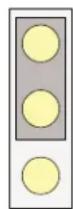
J39
CobraNet
SYNCHRONIZING TO AES/EBU
Method 2: Use the recovered AES 48 kHz clock as an "external clock" source. When the jumper at header J37 is set to "AES", the CobraNet interface uses the recovered 48 kHz clock at the first XLR connector (inputs 1 and 2) as the external synchronization clock. This method is similar to the "external synch" or "buddy link" mode of clock distribution in which an external clock is applied to the "synch input" BNC connectors on the rear panel of the RAVE. This method requires that the RAVE device be acting as the network conductor and be configured for external synchronization mode. External synchronization mode can be invoked by setting the left pair of hexadecimal switches on the RAVE's front panel to "80" or above. External synchronization can also be configured through software via SNMP.
Header J37 is located toward the far left side of the RAVE PCB just above the power supply capacitors and to the left of U137. The jumper configuration for implementing the "external clock" mode of AES synchronization is shown below.
The advantage to implementing the “external clock” method of AES synchronization is that the on-board PLL is still available should the RAVE lose the conductor role. This allows the RAVE device to function properly in the performer role. When acting as the conductor, local audio clocks are derived from the master clock sourced by the on-board PLL. The PLL is synchronized to an external clock, which happens to be the recovered 48 kHz clock from the AES receiver at the channel 1 input.
The disadvantage to using the "external clock" method is that the unit must be configured for external synchronization mode. Audio clocks are derived indirectly from the recovered 48 kHz AES stream.
It should be noted that external synchronization of the CobraNet network requires the on-board PLL. A RAVE AES/EBU device acting as the system conductor, which is synchronizing to an external clock applied to the rear panel "synch input", must not have its jumper at header J39 configured for "AES clock". This is a synchronization violation since the device cannot track the external clock source.

STATUS INDICATORS
The eight status indicator LEDs display the operating condition of the RAVE unit and its connection to the Ethernet network. They are color coded such that green LEDs, when illuminated, signify a good or normal condition, while red LEDs signify a problem. The “Conductor” LED is yellow and simply indicates whether the unit is providing system synchronization and accessibility functions.
Network activity LEDs

G = green colored
R = red colored
Y = yellow colored
Link
This LED illuminates green when the unit has established a link to an operating Ethernet network. In normal operation, this LED remains constantly lit, as long as the circuitry detects the network carrier. If this LED is not illuminated, there is a fault, possibly at the network device or in the cable connection. Note that this indicator does not confirm that the link is 100 Mbps or that the network device is supported by RAVE.
100 Mbps
This LED illuminates green when the unit establishes a link to a 100BASE-TX Ethernet device. If this indicator does not illuminate, the RAVE has not established link with a supported Ethernet device. Check the network device hardware and or configuration. Note that network routers, 10 Mbps and 1000 Mbps links are not supported for directly interfacing to RAVE.
Rx
This green LED lights for 50 milliseconds or longer whenever the unit receives Ethernet data, whether it is addressed to the unit or not. This indicator will blink when receive activity is present. The activity of this indicator is dependent on the RAVE model and bundle type. This is a physical layer indicator and does not guarantee that data is being received properly at the CobraNet core.
Rx Error
This red LED illuminates for at least 1 second if the unit has trouble receiving CobraNet related data. If illuminated, the failure may be due to problems with Ethernet reception, overcommitted transmission, excessive network delay or an internal fault. This indicator will also illuminate with the TxError LED if the device cannot synchronize to the network clock.
Tx
This LED illuminates green for at least 50 milliseconds while the unit is transmitting Ethernet data. This indicator will blink when transmit activity is present. The activity of this indicator is dependent on the RAVE model and bundle type. This is a physical layer indicator and does not guarantee that data is being transmitted properly from the CobraNet core.
Tx Error
This LED illuminates red for at least 1 second if a unit is having trouble transmitting CobraNet related data. Failure here may be due to network inaccessibility, duplicate transmit bundle assignments, improper network configuration or an internal fault. This indicator will also illuminate with the RxError LED if the device cannot synchronize to the network clock.
Conductor
This yellow LED will illuminate whenever the unit is acting as the system "conductor". In this mode, the unit provides the system synchronization and accessibility resources. Arbitration for the conductor role is initiated during system initialization or when a unit with a higher priority than the current conductor is added to the network. Conductor priority is based on the transmission capabilities of the device. The device with the least amount of transmission requirements is the best candidate for the conductor role. Currently, the hierarchy is as follows:
- RAVE 160s-24 and 80s highest
- RAVE 188s-24 and 88s mid position
- RAVE 161s-24 and 81s lowest
In the event there are two or more units with the highest priority arbitrating for the conductor role, the MAC address will be used as the deciding factor.

Note that there should be one, and only one, conductor per LAN or VLAN. Multiple conductor indicators may point to an unintentional partition in the network architecture because of multicast filtering.
Fault
This red LED illuminates whenever the unit detects an unexpected internal fault. If the RAVE unit cannot pass its self-induced self-test (POST), the fault indicator will usually repeat a sequence of flashes, which indicates where the POST failure occurred. If the RAVE does pass the self-test but cannot perform or continue its operation, a blink code consisting of three flash patterns may be repeated on the fault indicator. Additionally, the RAVEs audio metering LEDs may display a binary fault code. Fault codes are provided by Peak Audio for each major release of CobraNet code. When communicated by the user, these front panel fault code displays may help QSC's Technical Services department in providing a quick remedy for a faulty RAVE unit.
AUDIO SIGNAL LEVEL INDICATORS
The tricolor metering LEDs provide visibility to various configuration and metering information. Their primary purpose is to detect the presence of audio signal. However, the metering LEDs also perform device monitoring functions such as indicating the CobraNet firmware revision installed in the RAVE, error reporting, indicating "write" mode for MI use, indicating "software kill", bundle assignments and providing "bundle activity" status. For all of these device monitoring functions, the 16 metering LEDs are split into two 8-channel groups. The current signal LED indicating functions for the RAVE products are described below.
AUDIO METERING
Each audio channel on RAVE has its own metering LED. The audio channel signal LEDs' primary function is to provide audio metering for each of the 16 audio channel inputs, outputs or a combination of 8 inputs and 8 outputs. In the metering mode, the tricolor LEDs (green, yellow and red) provide an indication of the amount of signal present as well as the amount of headroom available. The signal level at which the LED's three colors are tripped is dependent upon the input sensitivity selected for each channel (analog models) or the AES signal's relation to DFS (digital full scale). Refer to the section on sensitivity selection (p.16) for details on input levels. In relation to digital full scale, the indicators react as follows:
- Bright green—when the channel's peak level is above -40dBFS (40dB below digital full scale).
• Yellow—when the signal peaks exceed -12dBFS - Red—when the signal peaks reach -2dBFS and above.
During normal operation, the channel signal indicators should be flashing bright green or yellow, and perhaps once in a while, a quick flash of red. If an LED stays dim green, the signal level is too low and you're not taking full advantage of the digital headroom. If an LED glows red often and for long durations, the signal level is probably too high and you'll experience digital "clipping," which tends to be very harsh. As with any audio device, you should consider the dynamic nature of the program material in judging the correct level indications.
CobraNet VERSION
When powering up a RAVE with CobraNet version 2, the major and minor release of the firmware is displayed on the two 8-channel groups in binary format. The left group displays the major release and the right group displays the minor release. For example, if the CobraNet version in the RAVE is 2.8.5, the left group would display a binary 8 and the right group would display a binary 5. If a "1" indicates illumination and a "0" indicates that the LED is off, 8.5 would be displayed as "0000100000000101" on the front-panel of the RAVE. The CobraNet version is displayed in red when the box is in hardware mode. In this default mode, bundle assignments and configuration setup is through the front panel hexadecimal switches. The CobraNet version is illuminated in yellow when the RAVE is in "write" mode and all configuration setup is accomplished through the Management Interface via SNMP. In "write" mode, the "flashPersistEnable" MI variable is set and the front panel switches are used for unit I.D.
ERROR REPORTING
Each release of the CobraNet firmware has an associated list of error codes, which identifies a specific cause in the event that a unit is failing a self-test or is experiencing operational problems. The RAVE devices may display this error code on the right 8-channel group of the metering LEDs. This code will be displayed in binary format with red LEDs. In the event that a unit should fail, this code can assist a Technical Services representative to troubleshoot the cause.
BUNDLE ASSIGNMENT
When implementing stand-alone control of the bundle assignments on RAVE products, the binary value of the address is temporarily displayed on the metering LEDs in red. This can be seen by scrolling through the front panel hexadecimal switches and viewing the metering display. Each time a switch is adjusted, the new value of the bundle assignment is quickly displayed. The value of the left-most pair of hex switches is displayed on the left 8-channel group of metering LEDs and the value of the right pair of hex switches is displayed on the right group of metering LEDs. Note that changing the bundle assignment of CobraNet bundles via SNMP has no effect on the metering LEDs.
BUNDLE ACTIVITY
One of the most useful features of the metering LEDs on RAVE products is that they indicate CobraNet connectivity information by providing "bundle activity" status. An active or valid bundle assignment is indicated by illuminating the associated 8-channel group of metering LEDs in dim green. Once viewed, the brightness difference between actual signal presence and bundle activity is very clear. When in multicast mode, the 8-channel transmit group will be illuminated in dim green so long as only one transmitter occupies any bundle assignment. Remember that multiple transmitters on the same bundle assignment creates an invalid condition. This condition applies to both multicast and unicast traffic types. See the Peak Audio website for the exception to this rule with "private" bundles. Note that multicast transmit bundles will be indicated by the dim green display whether or not there are active receivers tuned-in to the same bundle. Multicast receivers will also be indicated by the dim green display so long as there is an active transmitter occupying the same bundle assignment. Multiple receivers will be indicated in multicast mode only.
In unicast mode, an active transmitter will be displayed in dim green only if there is an active receiver on the same bundle assignment. Conversely, an active unicast receiver will only be displayed when a valid transmitter is active on the same bundle assignment.
In short, an active transmitter in multicast mode requires that only one transmitter be active on any bundle assignment. A valid multicast transmitter does not require a receiver to be "listening". In unicast mode, an active transmitter does require that a receiver be listening. To help clarify, consider the following; multicast traffic is analogous to a radio station such that the station is broadcasting program material whether or not there are listeners tuned-in. Unicast traffic is analogous to a telephone call such that a valid connection requires that one initiate the call and that a receiver accept the call.
PROGRAM AND "SOFTWARE KILL"
When all front panel hexadecimal switches are set to "FFFF", the RAVE unit enters a utility mode. This mode can be useful when reprogramming a RAVE or in disabling the software mode of operation.
Reprogramming through the RS-232 connection has given way to the network method, which uses TFTP (trivial file transfer protocol) over the Ethernet connection. The TFTP method creates the least amount of network disruption and provides the simplest implementation.
Since a RAVE may be configured via SNMP and retain its parameter settings, it is possible that a unit may arrive at an installation site where no method of interacting with the device through the software interface is possible. If a unit arrives in this "write" mode, the front panel hexadecimal switches will only affect the device I.D. No bundle or configuration setup is possible through the switch interface in this mode. Setting all front panel hexadecimal switches to "FFFF" and resetting (power cycling) the unit will provide a type of "software kill". The front panel switches can then be set to the desired bundle assignments and a second device reset will again implement hardware control.
ROUTING
A RAVE network routes audio signals in bundles of up to 8 channels. Behind the removable cover on the front panel are two pair of hexadecimal switches for assigning bundles to the 8-channel audio groups. Note that the following discussion only applies to front panel configuration of RAVE devices (stand-alone or "hardware" mode).

These 2 switches assign the bundle for:
RAVE 81/88/161/188: Transmit bundle assignment for audio input channels 1-8
RAVE 80/160: Receive bundle assignment for audio output channels 1-8
These 2 switches assign the bundle for:
RAVE 81/161: Transmit bundle assignment for audio input channels 9-16 RAVE 88/188: Receive bundle assignment for audio output channels 1-8 RAVE 80/160: Receive bundle assignment for audio output channels 9-16
The left pair of hexadecimal switches assign the bundle for audio channels 1 through 8 on all RAVEs.
-For RAVE 80 and 160: These are outputs, or the channels "received" off of the network
-For RAVE 81, 88, 161 and 188, these are input, or the channels "transmitting" onto the network
The right pair of switches assign the bundle for the remaining channels of the RAVE.
-For the RAVE 80/81/160/161, the right pair of switches apply routing to channels 9 through 16.
-For the RAVE 80/160, these are audio outputs.
- For the RAVE 81/161, these are audio inputs to be transmitted on the network.
- For the RAVE 88/188, the right pair of switches apply routing to channels 1-8.
To make a RAVE unit receive a bundle of CobraNet audio channels from a transmitting unit, set the receive unit's bundle switches to the same hex value as the transmitter.
Operation: Routing (continued)
Switches set to "10" through "FE" hex assign unicast bundles.
Switches set to "01" through "0F" hex assign multicast bundles.
Switch settings "00" and "FF" hex are reserved for special functions.
"FF" hex puts the unit into utility mode for programming and also forces software kill.
"00" hex disables a transmitter, thus preventing network bandwidth consumption when no audio transmission is required.
"00" hex disables a receiver from listening to any bundles.
Multicast addressing
(distributed to all devices)
| Front PanelHexadecimalSwitch Settings | Decimal Value | Bundle Type | MIParameter/Function | ||||
| First Pair | Second Pair | First Pair | Second Pair | ||||
| 0 | 1 | 0 | 1 | 1 | 1 | Multicast | Normal (distributed) |
| through | through | ||||||
| 0 | F | 0 | F | 15 | 15 | Multicast | Normal (distributed) |
Unicast addressing
(point-to-point
| Front PanelHexadecimalSwitch Settings | Decimal Value | Bundle Type | MIParameter/Function | ||||
| First Pair | Second Pair | First Pair | Second Pair | ||||
| 1 | 0 | 1 | 0 | 272 | 272 | Unicast | Normal (point-to-point) |
| through | through | ||||||
| 7 | F | 7 | F | 383 | 383 | Unicast | Normal (point-to-point) |
Unicast with
external synchronization
| Front PanelHexadecimalSwitch Settings | Decimal Value | Bundle Type | MIParameter/Function | ||||
| First Pair | Second Pair | First Pair | Second Pair | ||||
| 8 | 0 | 1 | 0 | 384 | 272 | Unicast | External Sync (pt.-to-pt.) |
| through | through | ||||||
| F | E | F | E | 510 | 510 | Unicast | External Sync (pt.-to-pt.) |
Special purpose
settings
| Front PanelHexadecimalSwitch Settings | Decimal Value | Bundle Type | MIParameter/Function | ||||
| First Pair | Second Pair | First Pair | Second Pair | ||||
| 0 | 0 | 0 | 0 | 0 | 0 | Null | No Transmit |
| F | F | F | F | 511 | 511 | Utility | Serial Program Mode |
| F | F | F | F | 511 | 511 | Utility | Software Kill (w/reset) |

NOTE! Bundle assignments should be limited to 4 multicast bundles per LAN on network switches.
All bundles are multicast on network repeaters.
Network Design Considerations: General Info and Switched Networks
There are a number of ways to design a CobraNet LAN. Several resources such as device specifications, Architect & Engineer's specifications, topology references, lists of approved network hardware and design guidelines are available on the Peak Audio website (www.pekaudio.com). Additionally, QSC Audio Products' website (www.qscaudio.com) posts up-to-date information on applications specific to RAVE and provides links to related resources. It is recommended that these resources be referred to before designing a CobraNet LAN. We offer the following general guidelines:
SWITCHED NETWORKS
- RAVE supports operation on 10/100 Mbps network switches. Switch ports must auto-negotiate their link with RAVE. The CobraNet portion of the LAN must consist only of switches such that all RAVEs are connected directly to an independent port on the switch. Non-CobraNet network devices, such as network Management consoles, may connect to a switched LAN by way of a network repeater.
Switches may be static "simple" switches or managed switches. Simple switches are much like traditional port bridges in that each port is its own 10/100 Mbps collision domain but the entire switch consists of a single broadcast domain. With these types of switches, multiple LANs or Virtual LANs (VLANs) are not supported and any broadcast frames or packets are available at all ports. In contrast, managed switches may allow configuration of VLANs, partitioning, packet filtering, and may support a number of features with the use of industry standard protocols. The actual feature support available depends on the switch model.
Sample switched network showing a managed CobraNet LAN

flowchart
graph TD
    A["Desktop PC #1"] --> B["Edge Switch"]
    B --> C["Core Switch"]
    C --> D["10/100 Mbit/s"]
    B --> E["RAVE 16s-24"]
    E --> F["AUDIO IN Network Bundle 1"]
    B --> G["Redundant Link"]
    G --> H["Printer"]
    H --> I["RAVE 81s"]
    I --> J["Desktop PC #2"]
    C --> K["Edge Switch"]
    K --> L["AUDIO OUT Network Bundle 2"]
    K --> M["RAVE 160s-24"]
    K --> N["AUDIO OUT Network Bundle 1"]
    style A fill:#f9f,stroke:#333
    style B fill:#ccf,stroke:#333
    style C fill:#cfc,stroke:#333
    style D fill:#fcc,stroke:#333
    style E fill:#ffc,stroke:#333
    style F fill:#cff,stroke:#333
    style G fill:#ffc,stroke:#333
    style H fill:#ffc,stroke:#333
    style I fill:#ffc,stroke:#333
    style J fill:#ffc,stroke:#333
    style K fill:#ffc,stroke:#333
    style L fill:#ffc,stroke:#333
    style M fill:#ffc,stroke:#333
Network Design Considerations: Switched Networks (continued)
When a switch is shared with non-CobraNet data, it should be configured so that CobraNet audio is isolated from conventional data communications. Partitioning is usually accomplished by enabling multiple VLANs. CobraNet data should be given the highest network priority in order to prevent the loss of audio. LAN, node, port and data or packet type prioritization can be defined through switch management software, industry protocols - such as Request For Comments (RFCs) supporting Quality of Service (QoS) - and through network design. Information on VLANs, QoS and network protocol support is available on the Peak Audio website and from a host of switch manufacturers.
- Try to assign unicast bundles between RAVE devices when operating on network switches. This provides point-to-point communications, which conserves bandwidth and prevents port flooding. As a rule of thumb, CobraNet supports up to four multicast bundles per broadcast domain or LAN. Audio delivery may be unreliable beyond this limit. If the benefit of switches is needed and the requirement exists for multiple receivers for a given bundle, it may be necessary to partition the network into smaller LANs. This results in multiple independent CobraNet networks on the same switch hardware, each LAN with its own “conductor”. Each LAN can then support up to four multicast bundles.
Conductor priority may also be a concern on network switches when implementing multicast traffic. The RAVE 160s-24 and 80s are currently assigned the highest “conductor” priority. Since these units have the least amount of transmission requirement, they are the best candidates for handling the “conductor” role. A transmitter with two outgoing bundles, such as the RAVE 161s-24, may be overly burdened if it is required to act as “conductor”, transmit both its bundles, receive unintended multicast
bundles and possibly service SNMP messages. The device defaults should handle these conditions appropriately. However, some configurations may require altering the "conductor" priority of some devices through the Management Interface.
- RAVE supports both stand-alone and software configuration. The default mode for RAVE is hardware control. In this mode, the bundle assignments are set through the front panel hexadecimal switches. These switches provide a subset of the available CobraNet bundle assignments. These switches also provide access to some configuration settings such as "external synchronization", "software kill", "serial programming" and selection between "unicast" and "multicast" addressing. You can quickly design a RAVE network right out of the box by simple configuration via the front panel switches.
In software mode, a RAVE is configured through the management interface using SNMP. With the MI, you can have access to additional bundle routing, complex internal audio mapping, audio channel duplication, "conductor" prioritization and more. Generally, a device is configured via SNMP application software and then the RAVE is placed into "write" mode so that all settings are written into permanent memory. The RAVE can then be moved or power-cycled without the loss of its configuration.
Also in software mode, the front panel switches are used to provide a unique network name for each RAVE. This name can be seen in the "sysName" variable within SNMP. Setting the front panel switches to "FFFF", and power-cycling the unit, brings the RAVE out of software control. This "software kill" feature provides a means to return a RAVE to stand-alone control in the event a management console or application software is unavailable.
Network Design Considerations: Repeater Networks
REPEATER NETWORKS
- RAVE supports operation on network repeaters. These repeaters should be 100 Mbps class II devices. Collisions are prevented through CobraNet's proprietary "order persistent" media access scheme. RAVE invokes this access scheme by auto-sensing its link partner (network hardware). In order to reliably connect to a network repeater, the class II device should not support auto-negotiation or 10 Mbps operation.
All bundle distribution is multicast on network repeaters. Additionally, since repeaters provide a half-duplex connection to a shared media network, there is a limit of 8 bundles per LAN. This translates to a maximum of 64 audio channels per 100 Mbps LAN. A repeater network must also be dedicated to CobraNet communications only. Non-CobraNet data should not be directly connected to the same network repeater. However, RAVE does provide a means to bridge serial data onto Ethernet via its RS-232 interface. As with CobraNet audio on repeater ports, serial data transmissions are available at all RS-232 ports.
Sample repeater network using Ethernet hubs with media conversion
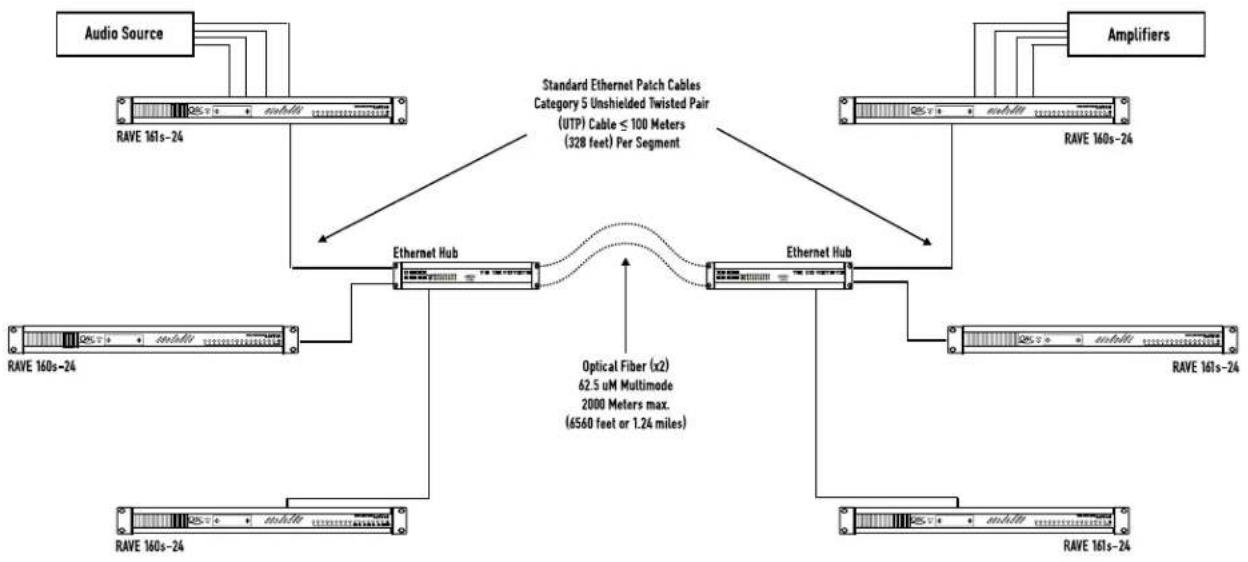
flowchart
graph TD
    A["Audio Source"] --> B["RAVE 161s-24"]
    B --> C["Ethernet Hub"]
    C --> D["Standard Ethernet Patch Cables Category 5 Unshielded Twisted Pair (UTP) Cable ≤ 100 Meters (328 feet) Per Segment"]
    D --> E["Amplifiers"]
    E --> F["RAVE 160s-24"]
    F --> G["Ethernet Hub"]
    G --> H["RAVE 161s-24"]
    H --> I["Optical Fiber (x2) 62.5 µM Multimode 2000 Meters max. (6560 feet or 1.24 miles)"]
    I --> J["RAVE 160s-24"]
    J --> K["Ethernet Hub"]
    K --> L["RAVE 161s-24"]
Specifications
GENERAL
| AC Line Voltage: | 100V to 240V, auto-configuring |
| AC Line frequency: | 50 Hz to 60 Hz, auto-configuring |
| Maximum AC Line Current Draw: | 600 mA @ 100V |
| Thermal Operating Range: | 0^ C to 65^ C |
ANALOG INPUTS
| Connector Type: | 3-pin Phoenix (euro-style), detachable terminal block |
| Audio Resolution (Tx): | 16, 20, 24-bit (software configurable) |
| Input Sensitivity: | +12 dBu, +18 dBu, +24 dBu, ±0.5 dB (via internal jumper selection) |
| Input Impedance: | >8k ohms (balanced) @ +12 dBu input sensitivity |
| >16k ohms (balanced) @ +18 dBu input sensitivity | |
| >33k ohms (balanced) @ +24 dBu input sensitivity | |
| Frequency Response: | 20 Hz to 20 kHz, ±0.5 dB |
| Dynamic Range, typical: | 108 dB FS @ 997 Hz |
| Dynamic Range, worst-case: | >106 dB FS @ 997 Hz |
| Signal-to-Noise (A-weighted): | 110 dB FS (20 Hz to 20 kHz), typical |
| THD+N @ 997 Hz: | .001 %, typical |
| THD+N (20 Hz to 20 kHz): | <.006 %, worst-case |
| Inter-channel Isolation: | >85 dB separation |
| Common Mode Rejection: | >50 dB (20 Hz to 20 kHz) |
AES3 INPUTS
| Connector Type: | XLR, female |
| Audio Resolution: | 20-bit with sample-rate-conversion |
| Sample Rate Support: | 32 kHz, 44.1 kHz, 48 kHz |
| Input Impedance: | 110 ohms (balanced), transformer coupled |
| Dynamic Range: | >120 dB FS(component datasheet spec.) |
| THD+N (20 Hz to 20 kHz): | >96 dB FS(component datasheet spec.) |
ANALOG OUTPUTS
| Connector Type: | 3-pin Phoenix (euro-style), detachable terminal block |
| Audio Resolution (Rx): | 16-, 20-, or 24-bit (auto-configuring) |
| Output Level: | +6 dBu, +12 dBu, +18 dBu, +24 dBu (via internal jumper selection) |
| Output Level Pad: | +1 dB @ 100k ohm load, typical <-.5 dB @ 600 ohm load |
| Maximum Load: | 600 ohms minimum |
Specifications
ANALOG OUTPUTS (continued)
| Output Impedance: < | 200 ohms (electronically balanced) |
| Frequency Response: | 20 Hz to 20 kHz, ±0.5 dB |
| Dynamic Range, typical: | 102 dB FS @ 997 Hz |
| Dynamic Range, worst-case: | >100 dB FS @ 997 Hz |
| Idle Channel Noise (A-weighted): | 104 dB FS (20 Hz to 20 kHz), typical |
| THD+N @ 997 Hz: | .001 %, typical |
| THD+N (20 Hz to 20 kHz): | <.006 %, worst-case |
| Inter-channel Isolation: | >85 dB separation |
AES3 OUTPUTS
| Connector Type: | XLR, male |
| Audio Resolution (Rx): | 16, 20, 24-bit (auto-configuring) |
| Output Impedance: | 110 ohms (balanced), transformer coupled |
REAR PANEL CONNECTIONS
| Female RJ-45 | 100BASE-TX Ethernet receptacle for CAT-5 UTP cable. |
| Female DB-9 | Provides serial bridge, RS-232 to Ethernet (requires host PC and straight-through cable) |
| Female BNC (x2): | "Sync Output" provides word clock output and keep-alive signal for redundant operation."Slave Input" provides external word clock input and receives keep-alive signal for redundant operation. |
| IEC male power receptacle: | For AC lines power connection |
DELAY SPECIFICATIONS
| Component | Sample Delay | Timing Delay |
| A/D converter (AK5392) | 38 792 microseconds | |
| D/A converter (CS4390) | 25 521 microseconds | |
| AES transmitter (CS8401) | 2 42 microseconds | |
| AES receiver (CS8411) | 2 42 microseconds | |
| Sample rate converter (AD1890) | 37 770 microseconds | |
| Audio buffering (CobraNet core) | 256 5.333 milliseconds |
Network device delay
| Device Forwarding Delay | |
| Class II repeater (network hub) <460 nanoseconds | |
| Category 5 UTP cable | approximately 11 nanoseconds per linear meter (round trip) |
| Multimode fiber optic cable | approximately 10 nanoseconds per linear meter (round trip) |
| Network switch: refer to CobraNet store and forward delay specification | |
Specifications Subject To Change Without Notice
AUDIO BUFFERING 256 samples (5.333 microseconds)
NETWORK
Protocol: 100 Mbps FAST Ethernet (FE)
Configuration: Network repeaters OR switches
Audio Channel Capability: 64 channels maximum PER repeater LAN, scalable for network switches
Management Protocol: SNMP (Simple Network Management Protocol)
Auxiliary Feature Support: Serial data support of RS-232 bridged onto Ethernet
Device upgrade via TFTP
Device configuration via hardware interface OR software interface
Cable Type: CAT-5 UTP (unshielded twisted pair)
Network Device Delay: Class II repeater (network hub) <460 nanoseconds
CAT-5 UTP cable \~ 11 nanoseconds per linear meter (round trip)
Multimode fiber optic cable 10 nanoseconds per linear meter (round trip)
Network switch : refer to CobraNet "store & forward" delay specification

Peak Audio and QSC provide support for audio networks built with repeaters, switches and media converters only. (QSC support is only available if the network uses QSC CobraNet products such as RAVE.)
Network products distributing CobraNet audio must meet specific timing requirements. Audio distribution via routers, gateways, protocol bridges, ATM, wireless transceivers, telecom or other WAN products is sometimes possible, but may prove unreliable and may require custom (contracted) support and some trial and error experimentation. Further information is available on the Peak Audio website: http://www.pekaudio.com
SYNCHRONIZATION
Master/Sync Output: 5 volts peak-to peak from 50 ohm BNC connector
Slave/Sync Input: Use to synchronize network to an external clock source or Slave input for redundant operation
50 ohm BNC connector
15 kHz. to 49.5 kHz. valid range of input frequency
To enable Sync: front panel hexadecimal switches must be set between 80 and FE hex or configure via SNMP.
To use as Slave: connect to Master via coax cable Sync, then duplicate hexadecimal switch settings (see pages 16 and 17).
MISC.
Chassis Power Connector Type: IEC, fully filtered for RFI and EMI
Fuse: 2 ampere, 250 VAC, 20mm long X 5mm diameter, 2 required
Appendix
ETHERNET CABLING
This diagram shows the pinout for standard unshielded twisted-pair (UTP) network cable. Both ends of the cable are wired identically.

A crossover cable has the RX and TX wire pairs switched around at one end. There are only two likely situations that would require a crossover cable: to connect two RAVE devices directly, without a repeater or other device in between; and to cascade repeaters or switches that don't have uplink ports.
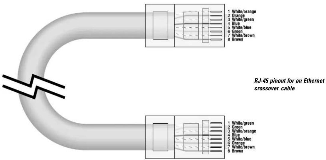
The wire in UTP cabling is twisted together in pairs. Rather than randomly choosing a wiring scheme for the networking cable, it is important to have the RX wires in one pair and the TX wires in another pair, especially in longer cable runs.
RS-232 PORT INFORMATION
Pin assignments of 9-pin female D connector:
Pin 2: TX out
Pin 3: RX in
Pin 5: Ground
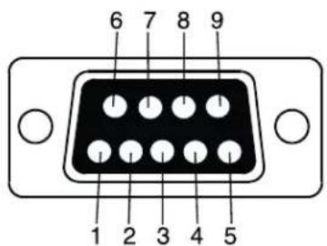
Pins 1 (DCD), 4 (DSR), and 6 (DTR) are tied together. Pins 7 (RTS) and 8 (CTS) are also tied together. DCE (receives on TD) operation; parity bit not checked.
QSC RAVE resources: http://www.qscaudio.com
- Visit our website regularly for up-to-date RAVE information such as:
Technology papers
Configuration procedures
Management aids
Internet links to other networked audio information sources
Client list (venues utilizing RAVE)
Articles and reviews
pdf versions of product documentation
CobraNet resources: http://www.pekaudio.com
- Peak Audio provides the official reference information for CobraNet. One of their currently available software tools available for free download is the CobraNet Discovery utility. This application enables users to assign IP addresses to their RAVE products as required by most management tasks. The utility provides many more useful features. CobraCAD is available for free as well. CobraCAD gives the user a design-rules -checker for designs as well as some network routing utilities.
- Visit their website for this and other network audio information, such as:
CobraNet tutorials
CobraNet specifications
CobraNet network theory and design
Network device requirements/specifications
Download available CobraNet tools
Information on the latest CobraNet release
List of qualified network hardware
Network Hardware Manufacturers
| 3-Com | Fore Systems | Alpha |
| Allied Telesyn | Hewlett-Packard | Belden Cable |
| Bay Networks | Intel | Black Box |
| Canary Communications | Linksys | CableMax |
| Cisco | M. Ian | Clark Wire & Cable |
| D-Link | Nortel | Coleman Cable |
| Edimax | SMC Networks | Consolidated Electronic Wore & Cable |
| Efficient Networks | Storageworks | Data Comm Warehouse |
| Extreme Networks | Transistion Networks | L-Com |
| Liberty Wire & Cable | ||
| Mogami Wire & Cable |
CAT-5 UTP Manufacturers
How to Contact QSC Audio Products
Product Warranty
QSC Audio Products, Inc. ("QSC") guarantees its products to be free from defective material and / or workmanship for a period of three (3) years from date of sale, and will replace defective parts and repair malfunctioning products under this warranty when the defect occurs under normal installation and use - provided the unit is returned to our factory or one of our authorized service stations via prepaid transportation with a copy of proof of purchase (i.e., sales receipt). This warranty provides that the examination of the return product must indicate, in our judgment, a manufacturing defect. This warranty does not extend to any product which has been subjected to misuse, neglect, accident, improper installation, or where the date code has been removed or defaced. QSC shall not be liable for incidental and/or consequential damages. This warranty gives you specific legal rights, and you may also have other rights which vary from state to state. This limited warranty is freely transferable during the term of the warranty period.
Disclaimer
QSC Audio Products, Inc. is not liable for any damage to speakers, amplifiers, or any other equipment that is caused by negligence or improper installation and/or use of any RAVE product. Due to the inherent complexity of network communications between RAVE units, QSC Audio Products, Inc. is not responsible for any direct or indirect damage caused by network communications failure. Some features of RAVE products are dependant upon Peak Audio's CobraNet firmware release version. QSC Audio Products, Inc. is not responsible for feature-set changes caused by changes in firmware versions set forth by Peak Audio.

Peak Audio and QSC provide support for audio networks built with repeaters, switches and media converters only. (QSC support is only available if the network uses QSC CobraNet products such as RAVE.)
Network products distributing CobraNet audio must meet specific timing requirements. Audio distribution via routers, gateways, protocol bridges, ATM, wireless transceivers, telecom or other WAN products is sometimes possible, but may prove unreliable and may require custom (contracted) support and some trial and error experimentation. Further information is available on the Peak Audio website: http://www.pekaudio.com
Address:
QSC Audio Products, Inc.
1675 MacArthur Boulevard
Costa Mesa, CA 92626-1468 USA
Facsimile Numbers:
Sales & Marketing FAX (714) 754-6174
Technical Services FAX (714) 754-6163
Telephone Numbers:
Main Number (714) 754-6175
Sales Direct Line (714) 957-7100
Sales & Marketing (800) 854-4079
(toll-free in USA only)
Technical Services (714) 957-7150
(800) 772-2834
(toll-free in USA only)

World Wide Web:
http://www.qscaudio.com

AUDIO
QSC Audio Products, Inc., 1675 MacArthur Boulevard Costa Mesa, California 92626 USA PH: (714) 754-6175 FAX: (714) 754-6174
RAVE is a trademark of QSC Audio Products, Inc. "QSC" and the QSC logo are registered with the U.S. Patent and Trademark Office
- RAVE
- "S" series Digital Audio Router
- USER MANUAL
- Attention!
- EXPLANATION OF GRAPHICAL SYMBOLS
- EXPLICATION DES SYMBOLES GRAPHIQUES
- AVIS
- RISQUE DE CHOC ÉLECTRIQUE NE PAS OUVRIR
- PRECAUTIONS
- FEDERAL COMMUNICATIONS COMMISSION (FCC)
- INFORMATION
- RAVE "S" Series Digital Audio Router User Manual
- Introduction: How It Works (continued)
- Introduction: Channel Routing
- Channel Routing
- Bundle Setup:
- PRE-INSTALLATION PREPARATION: ANALOG AUDIO SIGNAL LEVELS (RAVE 160/161/188 ONLY)
- Input Level Sensitivity (RAVE 161s-24 and 188s-24 only)
- Output Levels (RAVE 160s-24 and 188s-24 only)
- RACK MOUNTING (ALL MODELS)
- Connections: 100BASE-TX Ethernet
- ETHERNET CONNECTION (ALL MODELS)
- ANALOG AUDIO CONNECTIONS
- To connect a wire to a terminal:
- DIGITAL AUDIO CONNECTIONS
- Connections: AC Power and Fuses, Master/Sync Output and Slave/Sync Input
- AC POWER:
- FUSES:
- MASTER/SYNC OUTPUT
- SLAVE/SYNC INPUT
- Configuration example for redundant audio transmission
- Configuration example for redundant audio reception
- REDUNDANT CONFIGURATION (hardware setup)
- RS-232 PORT
- SYNCHRONIZING TO AES/EBU
- STATUS INDICATORS
- Link
- Mbps
- Rx
- Rx Error
- Tx
- Tx Error
- Conductor
- Fault
- AUDIO SIGNAL LEVEL INDICATORS
- AUDIO METERING
- CobraNet VERSION
- ERROR REPORTING
- BUNDLE ASSIGNMENT
- BUNDLE ACTIVITY
- PROGRAM AND "SOFTWARE KILL"
- ROUTING
- The left pair of hexadecimal switches assign the bundle for audio channels 1 through 8 on all RAVEs.
- The right pair of switches assign the bundle for the remaining channels of the RAVE.
- Operation: Routing (continued)
- Network Design Considerations: General Info and Switched Networks
- SWITCHED NETWORKS
- Network Design Considerations: Switched Networks (continued)
- Network Design Considerations: Repeater Networks
- REPEATER NETWORKS
- Specifications
- NETWORK
- SYNCHRONIZATION
- MISC.
- Appendix
- ETHERNET CABLING
- RS-232 PORT INFORMATION
- QSC RAVE resources: http://www.qscaudio.com
- CobraNet resources: http://www.pekaudio.com
- How to Contact QSC Audio Products
- Product Warranty
- Disclaimer
- Address:
- Facsimile Numbers:
- Telephone Numbers:
- World Wide Web:
Brand : QSC
Model : RAVE 80s
Category : Processor