
PS 128 - Power Supply Extron - Free user manual and instructions
Find the device manual for free PS 128 Extron in PDF.


| Product Type | Power Supply |
| Brand | Extron |
| Model | PS 128 |
| Input Voltage | 100-240 VAC, 50/60 Hz |
| Output Voltage | 12 VDC |
| Output Current | 1.5 A |
| Power Rating | 18 W |
| Dimensions (H x W x D) | 30 mm x 80 mm x 100 mm |
| Weight | 0.3 kg |
| Connector Type | 2.1 mm DC barrel jack |
| Operating Temperature | 0°C to 40°C |
| Storage Temperature | -20°C to 60°C |
| Protection Features | Overload, short circuit, overvoltage |
| LED Indicator | Power on (green) |
| Compliance | CE, FCC Class B |
| Cooling | Natural convection |
| Mounting | Desktop or wall-mountable |
| Input Cable Length | 1.5 m |
| Output Cable Length | 1 m |
| Included Accessories | Power cord, rubber feet |
Frequently Asked Questions - PS 128 Extron
User questions about PS 128 Extron
0 question about this device. Answer the ones you know or ask your own.
Ask a new question about this device
Download the instructions for your Power Supply in PDF format for free! Find your manual PS 128 - Extron and take your electronic device back in hand. On this page are published all the documents necessary for the use of your device. PS 128 by Extron.
USER MANUAL PS 128 Extron
Multiple Output 12 Volt DC Power Supply

Safety Instructions
Safety Instructions • English
WARNING: This symbol, , when used on the product, is intended to alert the user of the presence of uninsulated dangerous voltage within the product's enclosure that may present a risk of electric shock.
ATTENTION: This symbol, △when used on the product, is intended to alert the user of important operating and maintenance (servicing) instructions in the literature provided with the equipment.
For information on safety guidelines, regulatory compliances, EMI/EMF compatibility, accessibility, and related topics, see the Extron Safety and Regulatory Compliance Guide, part number 68-290-01, on the Extron website, www.extron.com.
© 2019 Extron Electronics. All rights reserved.
Trademarks
All trademarks mentioned in this guide are the properties of their respective owners. The following registered trademarks ( ^® ), registered service marks ( ^SM ), and trademarks ( ^TM ) are the property of RGB Systems, Inc. or Extron Electronics (see the current list of trademarks on the Terms of Use page at www.extron.com):
| Registered Trademarks ^(0) |
| Extron, AVTrac, Cable Cubby, CrossPoint, DTP, eBUS, EDID Manager, EDID Minder, Flat Field, FlexOS, Global Configurator, GlobalViewer, Hideaway, Inline, IP Intercom, IP Link, Key Minder, LinkLicense, LockIt, MediaLink, MediaPort, NetPA, PlenumVault, PoleVault, PowerCage, PURE3, Quantum, SoundField, SpeedMount, SpeedSwitch, System INTEGRATOR, TeamWork, TouchLink, V-Lock, VersaTools, VN-Matrix, VoiceLift, WallVault, WindoWall, XTP, and XTP Systems |
| Registered Service Mark ^(SM) : S3 Service Support Solutions |
| Trademarks ^(TM) |
| AAP, AFL (Accu-Rate Frame Lock), ADSP (Advanced Digital Sync Processing), Auto-Image, CableCover, CDRS (Class D Ripple Suppression), DDSP (Digital Display Sync Processing), DMI (Dynamic Motion Interpolation), Driver Configurator, DSP Configurator, DSVP (Digital Sync Validation Processing), eLink, EQIP, FastBite, FOX, FOXBOX, IP Intercom HelpDesk, MAAP, MicroDigital, ProDSP, QS-FPC (QuickSwitch Front Panel Controller), Room Agent, Scope-Trigger, ShareLink, SIS, Simple Instruction Set, Skew-Free, SpeedNav, Triple-Action Switching, True4K, Vector ^TM 4K, WebShare, XTRA, ZipCaddy, ZipClip |
FCC Class B Notice
NOTE: This device complies with part 15 of the FCC rules. Operation is subject to the following two conditions: (1) This device may not cause harmful interference, and (2) This device must accept any interference received, including interference that may cause undesired operation.
This equipment has been tested and found to comply with the limits for a Class B digital device, pursuant to part 15 of the FCC rules. These limits provide reasonable protection against harmful interference in a residential installation. This equipment generates, uses, and can radiate radio frequency energy and, if not installed and used in accordance with the instructions, may cause harmful interference to radio communications. There is no guarantee that interference will not occur. If this equipment does cause interference to radio or television reception, which can be determined by turning the equipment off and on, you are encouraged to try to correct the interference by one or more of the following measures:
- Reorient or relocate the receiving antenna.
- Increase the separation between the equipment and receiver.
- Connect the equipment into an outlet on a circuit different from that to which the receiver is connected.
- Consult the dealer or an experienced radio/TV technician for help.
In order to maintain compliance with FCC regulations, shielded cables must be used with this equipment. Operation with non-approved equipment or unshielded cables is likely to result in interference to radio and TV reception. The user is cautioned that changes and modifications made to the equipment without the approval of the manufacturer could void the user's authority to operate this equipment.
This Class B digital apparatus complies with Canadian ICES-003.
NOTE: For more information on safety guidelines, regulatory compliances, EMI/EMF compatibility, accessibility, and related topics, see the “Extron Safety and Regulatory Compliance Guide” on the Extron website.
VCCI-B Notice
Conventions Used in this Guide
Notifications
The following notifications are used in this guide:
WARNING: Potential risk of severe injury or death.
NOTE: A note draws attention to important information.
TIP: A tip provides a suggestion to make working with the application easier.
Specifications Availability
Product specifications are available on the Extron website, www.extron.com.
Extron Glossary of Terms
A glossary of terms is available at http://www.extron.com/technology/glossary.aspx.
Contents
Introduction....1
Guide Overview....1
Product Description....1
Features 2
Installation and Operation .... 3
Rear Panel Features .... 3
Front Panel Features....5
Mounting....6
Tabletop 6
Rack....6
UL Guidelines for Rack-Mounted Devices......6
Rack-Mounting....7
Furniture 7
Projector in a PoleVault System 7
Introduction
This section provides general information about the this guide, the PS 128 Power Supply, and features. Topics in this section include the following:
- Guide Overview
• Product Description - Features
Guide Overview
This guide contains information about installing and operating the PS 128 Power Supply. In this guide, the terms “PS 128” and “power supply” refer to the PS 128 Power Supply.
Product Description
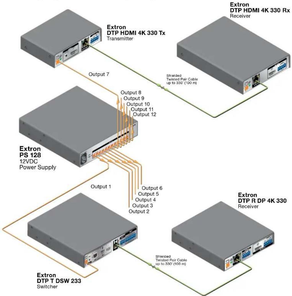
The PS 128 is a rack-mountable, multiple output 12 volt DC power supply. It delivers a total of 8.0 amps across all outputs with no per-port current limitations, allowing connected devices to receive current based on load requirements. The PS 128 reduces the number of desktop power supplies by providing power for up to twelve devices, resulting in power consolidation and centralized power management (see figure 1 on the next page for an example of a typical application).
The following diagram shows a PS 128 powering two devices.
flowchart
graph TD
    A["Extron DTP HDMI 4K 330 Rx"] -->|Transmitter| B["Extron DTP HDMI 4K 330 Tx"]
    B -->|Output 7| C["Extron PS 128 12VDC Power Supply"]
    B -->|Output 8 Output 9 Output 10 Output 11 Output 12| D["Extron DTP T DSW 233 Switcher"]
    B -->|Shielded Twisted Pair Cable up to 330' (100 m)| E["Extron DTP R DP 4K 330 Receiver"]
    B -->|Output 1| F["Extron DTP T DSW 233 Switcher"]
    B -->|Output 6 Output 5 Output 4 Output 3 Output 2| G["Extron DTP R DP 4K 330 Receiver"]
Figure 1. Typical Application Diagram
Features
- Outputs — Provides twelve 12 volt DC outputs, 8.0 amps total, using twelve 2-pin captive screw connectors.
• No per-port amperage limitation
• Up to 96 watts of power
• Dual-color status LED for normal operating and overload conditions - Rack-mountable 1U, one-half rack width, metal enclosure
Installation and Operation
This section contains installation instructions and indicator information. Topics in this section include the following:
- Rear Panel Features
- Front Panel Features
Rear Panel Features

A AC power input connector (see below)
B Overload LED indicator (see below)
© DC power output connectors (see page 4)
Figure 2. Rear Panel Features
AC power input connector — Connect a 100-240 VAC, 50-60 Hz power source to the AC power connector on the rear panel.
B Overload LED indicator — Lights green or red to indicate the power current status.
- Green — Power is applied and the collective current draw is normal (8 amps or less).
• Red — The PS 128 is in a current overload condition (more than 8 amps).
ATTENTION:
NOTE: To identify a shorted output, unplug the outputs one at a time until the LED lights green.
DC power output connectors — Connect up to 12 devices to these 2-pole, 3.5 mm captive screw connectors (see figure 2, on the previous page). Wire the connectors as shown in figure 3. Each output provides 12 VDC. Do not exceed 8 amps of combined current draw for the connected devices.

Figure 3. DC Power Output Wiring
WARNING: Electric shock hazard. The two power cord wires must be kept separate while the power supply is plugged in. Remove power before wiring.
- To verify proper polarity before connection to a device, plug in the power supply with no load and check the output polarity with a voltmeter. Remove power before continuing.
- Do not tin the stripped power supply leads. Tinned wires are not as secure in the captive screw connectors and could be pulled out.
Front Panel Features

Figure 4. Front Panel Features
A Overload LED indicator — Lights green or red to indicate the power current status. This is the same indicator as on the rear panel (see figure 2, B on page 3).
- Green — Power is applied and the collective current draw is normal (8 amps or less).
- Red — The PS 128 is in a current overload condition (more than 8 amps or 96 watts).
ATTENTION:
NOTE: To identify a shorted output, unplug the outputs one at a time until the LED lights green.
Mounting
This section contains basic mounting information. Topics in this section include the following:
- Tabletop
- Rack
- Furniture
- Projector in a PoleVault System
Tabletop
To place the PS 128 on a flat surface like a tabletop or desk, attach the provided rubber feet to the bottom four corners of the enclosure.
Rack
For mounting options in rack environments, go to www.extron.com for a list of compatible rack mounting kits. Follow the mounting kit instructions and see the UL guidelines for rack-mounted devices below.
UL Guidelines for Rack-Mounted Devices
The following Underwriters Laboratories (UL) guidelines pertain to the safe installation of the PS 128 in a rack.
- Elevated operating ambient temperature — If installed in a closed or multi-unit rack assembly, the operating ambient temperature of the rack environment may be greater than room ambient temperature, Therefore, install the PS 128 in an environment compatible with the maximum ambient temperature (Tma = +104 °F, +40 °C) specified by Extron.
- Reduced air flow — Install the equipment in a rack so that the amount of air flow required for safe operation of the equipment is not compromised.
- Mechanical loading — Mount the equipment in the rack so that a hazardous condition is not achieved due to uneven mechanical loading.
- Circuit overloading — Connect the equipment to the supply circuit and consider the effect that circuit overloading might have on overcurrent protection and supply wiring. Appropriate consideration of equipment nameplate ratings should be used when addressing this concern.
- Reliable earthing (grounding) — Maintain reliable grounding of rack-mounted equipment. Pay particular attention to supply connections other than direct connections to the branch circuit (for example, the use of power strips).
Rack-Mounting
The PS 128 is 1U high and half rack wide for rack-mounting. See the PS 128 specifications on www.extron.com for the device dimensions.
NOTE: If required, remove previously installed rubber feet on the bottom of the PS 128.

Figure 5. Mounting in a Rack Example
Furniture
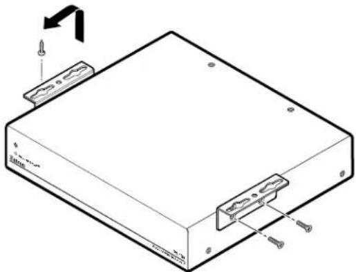
For mounting options under a table or desk, go to www.extron.com for a list of compatible furniture mounting kits. Follow the instructions provided with the kit.
natural_image
Technical line drawing of a rectangular electronic device with mounting hardware and screw base (no text or symbols)Figure 6. Mounting under a Desk Example
Projector in a PoleVault System
For mounting options in an Extron PoleVault system, go to www.extron.com for a list of compatible PoleVault mounting kits. Follow the instructions provided with the kit.
Extron Warranty
Extron Electronics warrants this product against defects in materials and workmanship for a period of three years from the date of purchase. In the event of malfunction during the warranty period attributable directly to faulty workmanship and/or materials, Extron Electronics will, at its option, repair or replace said products or components, to whatever extent it shall deem necessary to restore said product to proper operating condition, provided that it is returned within the warranty period, with proof of purchase and description of malfunction to:
USA, Canada, South America, and Central America:
Extron Electronics
1230 South Lewis Street
Anaheim, CA 92805
U.S.A.
Japan:
Extron Electronics, Japan
Kyodo Building, 16 Ichibancho
Chiyoda-ku, Tokyo 102-0082
Japan
Europe and Africa:
Extron Europe
Hanzeboulevard 10
3825 PH Amersfoort
The Netherlands
China:
Extron China
686 Ronghua Road
Songjiang District
Shanghai 201611
China
Asia:
Extron Asia Pte Ltd
135 Joo Seng Road, #04-01
PM Industrial Bldg.
Singapore 368363
Singapore
Middle East:
Extron Middle East
Dubai Airport Free Zone
F13, PO Box 293666
United Arab Emirates, Dubai
This Limited Warranty does not apply if the fault has been caused by misuse, improper handling care, electrical or mechanical abuse, abnormal operating conditions, or if modifications were made to the product that were not authorized by Extron.
NOTE: If a product is defective, please call Extron and ask for an Application Engineer to receive an RA (Return Authorization) number. This will begin the repair process.
USA: 714.491.1500 or 800.633.9876
Europe: 31.33.453.4040
Asia: 65.6383.4400 Japan: 81.3.3511.7655
Units must be returned insured, with shipping charges prepaid. If not insured, you assume the risk of loss or damage during shipment. Returned units must include the serial number and a description of the problem, as well as the name of the person to contact in case there are any questions.
Extron Electronics makes no further warranties either expressed or implied with respect to the product and its quality, performance, merchantability, or fitness for any particular use. In no event will Extron Electronics be liable for direct, indirect, or consequential damages resulting from any defect in this product even if Extron Electronics has been advised of such damage.
Please note that laws vary from state to state and country to country, and that some provisions of this warranty may not apply to you.
| Extron Headquarters+1.800.633.9876 (Inside USA/Canada Only)Extron USA - West Extron USA - East+1.714.491.1500 +1.919.850.1000+1.714.491.1517 FAX +1.919.850.1001 FAX | Extron Europe+800.3987.6673(Inside Europe Only)+31.33.453.4040+31.33.453.4050 FAX | Extron Asia+65.6383.4400+65.6383.4864 FAX | Extron Japan+81.3.3511.7656+81.3.3511.7656 FAX | Extron China+86.21.3760.1568+86.21.3760.1566 FAX | Extron Middle East+971.4.299.1800+971.4.299.1880 FAX | Extron Australia+61.8.8351.2188+61.8.8351.2511 FAX | Extron India1800.3070.3777Inside India Only+91.80.3055.3777+91.80.3055.3737 FAX |


- Safety Instructions
- Safety Instructions • English
- Trademarks
- FCC Class B Notice
- VCCI-B Notice
- Conventions Used in this Guide
- Notifications
- Specifications Availability
- Extron Glossary of Terms
- Contents
- Introduction....1
- Installation and Operation .... 3
- Mounting....6
- Introduction
- Guide Overview
- Product Description
- Features
- Installation and Operation
- ATTENTION:
- Front Panel Features
- Mounting
- Tabletop
- Rack
- UL Guidelines for Rack-Mounted Devices
- Rack-Mounting
- Furniture
- Projector in a PoleVault System
- Extron Warranty
- USA, Canada, South America, and Central America:
- Japan:
- Europe and Africa:
- China:
- Asia:
- Middle East:
Brand : Extron
Model : PS 128
Category : Power Supply