
PowerCage 411 - Power Supply Extron - Free user manual and instructions
Find the device manual for free PowerCage 411 Extron in PDF.


| Product Type | Power Supply Module |
| Brand | Extron |
| Model | PowerCage 411 |
| Input Voltage | 100-240 VAC, 50/60 Hz |
| Output Voltage | 12 VDC |
| Total Output Current | 4 A |
| Number of Outputs | 4 |
| Form Factor | Module for PowerCage enclosure |
| Cooling Method | Convection cooled |
| Protection Features | Overload, short circuit |
| LED Indicators | Power LED per output |
| Operating Temperature | 0 to 50 °C |
| Storage Temperature | -20 to 70 °C |
| Relative Humidity | 10% to 90% non-condensing |
| Compliance | CE, UL |
| Dimensions (H x W x D) | 1.7 in x 5.2 in x 3.5 in |
| Weight | 1.5 lb |
| Warranty | 3 years |
| Maintenance | Clean with dry cloth; avoid liquids |
| Safety Notes | Use in ventilated area; do not cover |
| Accessories Included | Power cord, mounting screws |
Frequently Asked Questions - PowerCage 411 Extron
User questions about PowerCage 411 Extron
0 question about this device. Answer the ones you know or ask your own.
Ask a new question about this device
Download the instructions for your Power Supply in PDF format for free! Find your manual PowerCage 411 - Extron and take your electronic device back in hand. On this page are published all the documents necessary for the use of your device. PowerCage 411 by Extron.
USER MANUAL PowerCage 411 Extron
PowerCage 411 Enclosure • Setup Guide
This setup guide contains installation information for the PowerCage 411 FOX3 Enclosure using step-by-step instructions. For complete instructions, see the PowerCage 411 Series User Guide at www.extron.com.

WARNING: Potential risk of severe injury. Installation and service must be performed by authorized personnel only.
Figure 1. PowerCage 411 Rear Panel
Power connectors 1 and 2 — Connect these ports to 110-240 VAC, 50-60 Hz power sources using standard IEC power cords.
B Slot 1 through Slot 4 — Install a PowerCage 411- compatible board into each slot.
© LAN port — Use an RJ-45 cable to connect to a LAN (Ethernet) for control of the device.
• Use a straight-through cable for connection to a switch, hub, or router.
• Use a crossover or a straight-through cable for connection directly to a PC.
Remote RS-232 port — To control the unit, connect an RS-232 device to the 3-pole, 3.5 mm captive screw port and configure it as follows: 9600 baud rate, 8 data bits, 1 stop bit, no parity.
Installing Boards into the Enclosure
Any combination of up to four boards can be installed in the PowerCage enclosure. The quantity and type of boards vary depending on the configuration for each installation site.
Before installing the boards in the enclosure, refer to the model-specific guide for each PowerCage board being installed. The guides describe the features of each board and how to set up and cable it.
NOTE: The power supplies and boards are hot-swappable; they can be installed or removed without turning off or disconnecting the power to the PowerCage 411 FOX3 Enclosure.
CAUTION:
- Use ESD precautions when installing a board to avoid damaging it. Keep the board in the anti-static bag until it is needed.
- Prenez les précautions ESD lorsque vous installez une carte afin d'éviter de l'endommager. Gardez la carte dans le sachet dépoussiérant jusqu'à ce que vous en ayez besoin.
- Use proper grounding techniques during installation.
-
Utilisez des techniques de mise à la terre correctes pendant l'installation.
-
Where applicable, remove as many blank plates or previously installed boards from the rear of the PowerCage Enclosure as necessary to accommodate the number of new boards to be installed.
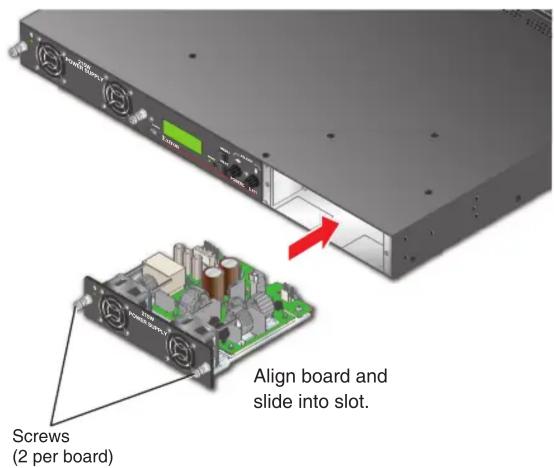
- Carefully slide the board into the slot, aligning the bottom edge of the board with the left and right board mounting slides on the bottom of the enclosure slot. Push the board completely into the slot and finger-tighten the two top screws while pushing in the screws to secure the board in place (see figure 2).
- Repeat step 2 for all boards needing installation.
NOTE: Cover all empty board slots; do not leave them open. Securely fasten the screws for all boards and blank panels.

Figure 2. Board Installation
Front Panel Features

Figure 3. PowerCage 411 FOX3 Front Panel
A Power supply LEDs —
| LED Color - State | Power Supply Status | Fan Status |
| Green - Solid Good | Both fans functional | |
| Red - Solid | Failed | Both fans functional |
| Orange - Solid | No AC power present | Both fans functional |
| Green - Blinking | Good | Either fan not functional |
| Red - Blinking | Failed | Either fan not functional |
| Orange - Blinking | No AC power present | Either fan not functional |
B Power supplies — Connect power to IEC power connector 1 or 2 (see figure 1, A on page 1).
© Fans — For power supplies.
Configuration port — If desired, connect a host device to the front panel USB mini-B port for configuring the enclosure.
NOTE: This port allows communication to the enclosure and the boards.
E LCD screen — The screen displays messages, menu information, and your selections (see Menus, Configuration, and Adjustments on page 3).
F Reset button and LED — Pressing the Reset button sets various enclosure settings to the factory default values. The LED lights green after pressing the Reset button (see the PowerCage 411 Series User Guide for details).
G Navigation buttons —
- MENU — Press MENU to access the PowerCage 411 menu system (see Menus, Configuration, and Adjustments).
- NEXT — From each menu press NEXT to step through submenus (see Menus, Configuration, and Adjustments).
H Navigation adjust knobs —
- Horizontal — Turn the horizontal adjust knob to navigate the menu system (see Menus, Configuration, and Adjustments).
- Vertical — Turn the vertical adjust knob to navigate the menu system (see Menus, Configuration, and Adjustments).
Menus, Configuration, and Adjustments
The PowerCage 411 FOX3 Enclosure has a menu system consisting of four main menus that are selected by pressing the front panel MENU button (see figure 3, Ⓖ on page 2). Each main menu consists of submenus that are accessed by pressing the front panel NEXT button (G). Use the front panel Horizontal and Vertical Adjust knobs (H) to make any submenu adjustments. See the following flowcharts:

flowchart
graph TD
    A["Power On"] --> B["Extron PowerCage 411"]
    B --> C["60-1492-02 FW v1.00.xxx"]
    C --> D["Default Cycle"]
    D --> E["Menu"]
    E --> F["SLOT MENU"]
    F --> G["Menu"]
    G --> H["FRAME STATUS MENU"]
    H --> I["Menu"]
    I --> J["VIEW COMM SETTINGS MENU"]
    J --> K["Menu"]
    K --> L["EXIT MENU"]
    L --> M["Next"]
    M --> D
    N["Menu"] --> L

flowchart
graph TD
    A["PowerOn"] --> B["Extron PowerCage 411"]
    B --> C["60-1492-02 FW v1.00.xxx"]
    C --> D["Slot #1 Fox3 T 301"]
    D --> E["Slot #2 N/A"]
    E --> F["Slot #3 Fox3 T 311"]
    F --> G["Slot #4 FOX3 T 201"]
    G --> H["Menu"]
    H --> I["SLOT MENU"]
    I --> D
    style D fill:#f9f,stroke:#333
    style E fill:#f9f,stroke:#333
    style F fill:#f9f,stroke:#333
    style G fill:#f9f,stroke:#333
    style H fill:#ccf,stroke:#333
    style I fill:#ccf,stroke:#333
Remote Control
The PowerCage 411 can be configured and controlled remotely using Simple Instruction Set (SIS) commands, Product Configuration Software (PCS), and the internal web pages.
NOTE: For details on all the remote control options, see the PowerCage 411 Series User Guide and PowerCage 411 Series PCS Help File.
Simple Instruction Set (SIS) Commands
Use SIS commands for operation and configuration of the PowerCage. Run these commands from a PC connected to:
- A LAN or WAN using the rear panel RJ-45 LAN connector (see figure 1, © on page 1) via an SSH client and port 22023.
- The Remote RS-232 port (see figure 1, D) via DataViewer.
- The front panel USB config port (see figure 3, D on page 2) via an SSH client and IP address 203.0.113.22 and port 22023.
Product Configuration Software (PCS)
Another way to operate the PowerCage is via PCS, which runs on computers that use the Windows® operating system. This program is available at www.extron.com. PCS can be run from a PC connected to the rear panel LAN port (see figure 1, ©) or front panel configuration port (see figure 3, D) on the PowerCage.
NOTE: An Extron Insider account is required to download and use PCS. Contact an Extron support representative to obtain an Insider Account.
Internal Web Pages
Another way to configure and operate the switcher is via its factory-installed internal web pages. The pre-loaded web pages on the PowerCage are accessible through the LAN port (see figure 1, C) via a LAN or WAN connection or the front panel USB config port (see figure 3, D) using a web browser.
NOTE: Compatible web browsers are Microsoft Edge , Mozilla Firefox , Google Chrome TM , and Apple Safari .
Mounting and Cabling
- Turn off or disconnect all equipment power sources.
- Mount the PowerCage 411 to a rack using the pre-installed rack ears or use the optional MBU mounting kit for under-desk mounting (see figure 4).


Figure 4. Mounting Diagrams
NOTES:
- For tabletop mounting, use the included rubber feet. Up to three units may be stacked together, one on top of the other.
-
The optional UTM 100 mounting kit may also be used to mount up to 2 units, one under the other.
-
Connect power to the rear panel IEC connector or connectors (see figure 1, A on page 1).
- Attach cables to the LAN and RS-232 ports, as applicable (see figure 1, C and D).
Replacing the Power Supply
- Use a screwdriver to rotate the left and right captive panel screws to completely loosen the screws.
- Gently but firmly pull on the screws to loosen the power supply from the backplane.
- Slide the power supply out of the enclosure.
- Orient the replacement power supply module to be installed.
- Center the replacement power supply module with the power supply opening.
- Gently slide the replacement power supply module into the enclosure until the power supply meets resistance.
- Gently seat the replacement power supply in the backplane.
- Use a screwdriver to tighten the left and right captive panel screws to lock the replacement power supply in place.
For information on safety guidelines, regulatory compliances, EMI/EMF compatibility, accessibility, and related topics, see the Extron Safety and Regulatory Compliance Guide on the Extron website.


- PowerCage 411 Enclosure • Setup Guide
- Installing Boards into the Enclosure
- CAUTION:
- Front Panel Features
- Menus, Configuration, and Adjustments
- Remote Control
- Simple Instruction Set (SIS) Commands
- Product Configuration Software (PCS)
- Internal Web Pages
- Mounting and Cabling
- NOTES:
- Replacing the Power Supply
Brand : Extron
Model : PowerCage 411
Category : Power Supply