
Quantum Ultra - Power Supply Extron - Free user manual and instructions
Find the device manual for free Quantum Ultra Extron in PDF.

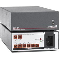
| Product Type | Hot-swappable Redundant Power Supply |
| Brand | Extron |
| Model | Quantum Ultra Power Supply |
| Compatible With | Extron Quantum Ultra videowall processor |
| Input Voltage | 100-240 VAC, 50/60 Hz |
| Power Output | 300 W (estimated) |
| Dimensions (H x W x D) | 1.7 x 4.4 x 8.9 inches (4.3 x 11.2 x 22.6 cm) |
| Weight | 2.2 lbs (1.0 kg) |
| Features | Hot-swappable, redundant operation, front access, locking lever |
| Installation | Slides into dedicated slot, secured with thumbscrews and lever |
| Replacement Kit Contents | Power supply unit, front and back plates (configured for primary slot) |
| Safety | Hot-swappable; disconnect power before servicing internal components |
| Maintenance | Replace failed unit promptly; no user-serviceable parts inside |
| Spare Parts / Repairability | Replacement PSU available from Extron; field-replaceable without tools |
| Compliance | CE, UL, FCC (typical for Extron equipment) |
Frequently Asked Questions - Quantum Ultra Extron
User questions about Quantum Ultra Extron
0 question about this device. Answer the ones you know or ask your own.
Ask a new question about this device
Download the instructions for your Power Supply in PDF format for free! Find your manual Quantum Ultra - Extron and take your electronic device back in hand. On this page are published all the documents necessary for the use of your device. Quantum Ultra by Extron.
USER MANUAL Quantum Ultra Extron
Replacing the Quantum Ultra® Power Supplies

The Quantum Ultra has a primary and a redundant power supply unit (PSU) to ensure continued, uninterrupted operation if a power supply should fail. However, if a power supply does fail, you should replace it as soon as possible. The power supplies are hot-swappable, that is, one can be replaced while the unit is operating with the other PSU supplying power.
NOTE: For full installation, configuration, and operation details, see the Quantum Ultra User Guide, available at www.extron.com.
Replacing the Primary Power Supply
This section describes the procedure for replacing the primary power supply. If the redundant power supply needs to be replaced, some additional steps are required (see Replacing the Redundant Power Supply on page 4).
To replace the Quantum Ultra primary power supply:
- Using a screwdriver or other tool, loosen the two thumbscrews on the power supply and the two thumbscrews on the protective cover panel (see figure 1, ①).
ATTENTION:
NOTE: The thumbscrews cannot be removed completely from the plates.

Figure 1. Unfastening the Power Supply
- Remove the cover panel ( ②).
- Rotate the primary power supply lever to the right ( ③) until it is in a horizontal position, parallel to the top and bottom of the unit.
NOTE: If you are removing the redundant power supply, rotate its lever (see figure 1, 4) to the right instead of the primary supply lever (3).
Replacing the Quantum Ultra Power Supplies (Continued)
- As you rotate the lever, the power supply slides to the right. If necessary, continue sliding the PSU to the right as far as possible (see figure 2, ①).

Figure 2. Rotating the Latch and Sliding the Primary Power Supply to the Right and Out
-
Lift the power supply up slightly and slide it toward you, out of the chassis ( ②).
-
Slide the new power supply into the empty slot vacated by the failed PSU, until its back panel is flat against the back wall of the power supply compartment.
NOTE: There are two keyhole slots in the back wall and one on the front surface of the power supply compartment. The power supply has three protruding pegs (see figure 3, ①).

natural_image
Pure technical diagram of a mechanical component with no text, numbers, or symbolsFigure 3. Pegs on the Back of the Power Supply
These pegs must be in the slots on the back wall and front surface of the power supply compartment when you slide the power supply all the way in. Otherwise, the power supply does not lie flat against the back of the compartment, so the levers cannot lock the PSU in place and the supply does not function.
If the power supply is in place, its front panel is flush with the front panel of the other power supply. If the new power supply is not even with the other one, slide the new one out again and lift it up slightly as you slide it in again, until it touches the back of the compartment.
-
When the power supply is in position, slide it to the left as far as you can without forcing it.
-
Ensure that the round end of the locking lever on the power supply (see figure 4, ②) is positioned between the two pegs (①), located on the chassis adjacent to the power supply, then rotate the lever to the left until the power supply is locked in place.
NOTE: If replacing the redundant power supply, position lever ④ between the two pins on the bottom unit (③).
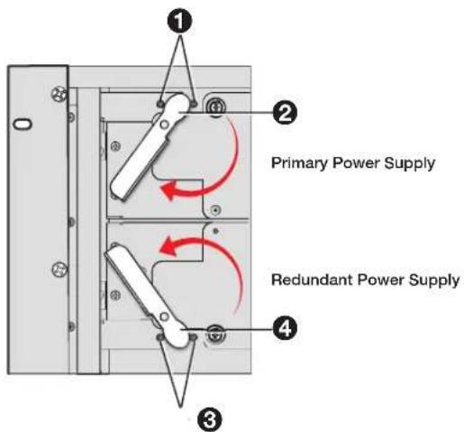
Figure 4. Positioning the Lever between the Two Pegs on the Chassis
- Use a tool to tighten the two thumbscrews on the power supply as follows:
a. Grasp the screw firmly and press it inward.
b. Continue to press inward as you turn the screw to the right, until it is securely in place.
- Reattach the protective cover panel.
Replacing the Redundant Power Supply
Replacing the redundant (bottom) power supply requires some additional steps to be performed prior to the procedure described in the previous section. The primary and redundant power supplies are essentially the same unit, but they are configured slightly differently in order to fit into their slots in the chassis.
The replacement power supply kit is shipped with the power supply configured to replace the top (primary) PSU. If the lower (redundant) power supply fails instead, you must replace the front and back metal plates of the new PSU with those of the failed redundant power supply.
To replace a failed redundant power supply:
- Perform steps 1 through 5 of the primary power supply replacement procedure, starting on page 1, to remove the redundant power supply from the chassis.
- Remove the front plate (containing the latch, handle, and thumbscrews) from the failed redundant power supply by unfastening the three round-headed Philips screws at the top of the plate (see figure 5). (Retain the front plate and screws to attach to the replacement power supply in step 5).
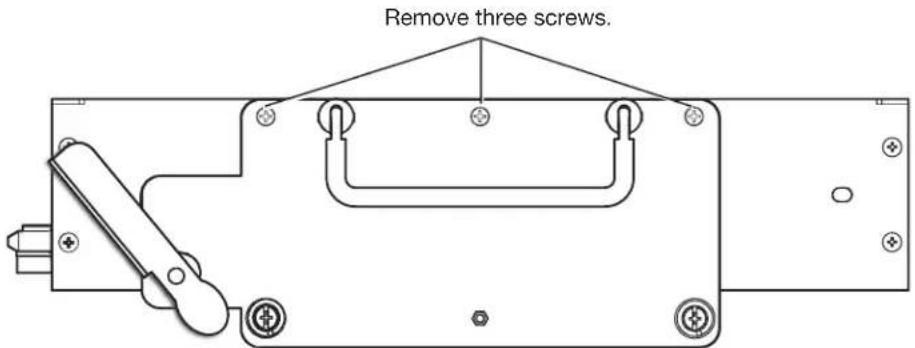
Figure 5. Removing the Plate from the Failed Redundant Power Supply Front Panel
- Remove the metal strip from the back of the failed redundant power supply by unfastening the three flat-headed screws (see figure 6). (Retain the back plate and screws to reattach the strip in step 6).
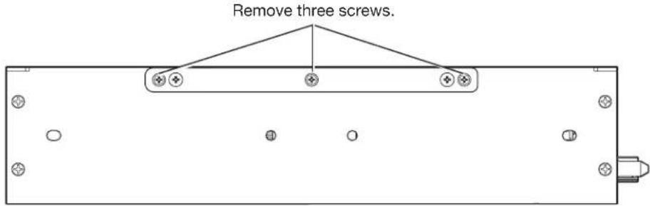
Figure 6. Removing the Metal Strip from the Failed Redundant Power Supply Back Panel
- Remove the front and rear panels from the replacement power supply by unfastening the three screws on the front and back panels. (These panels and screws will not be needed again.)
- Attach the front plate that was removed from the failed redundant power supply in step 2 to the three holes on the back panel of the replacement power supply. Use the three round-headed screws that also were removed in step 2.
- Attach the metal strip from the back of the failed power supply to the three holes on the front of the replacement power supply, using the three flat-headed screws removed in step 3.
- Perform the steps 6 through 10 of the primary power supply replacement procedure, on page 3.
| Extron Headquarters+800.633.9876 Inside USA/Canada OnlyExtron USA - West Extron USA - East+1.714.491.1500 +1.919.850.1000+1.714.491.1517 FAX +1.919.850.1001 FAX | Extron Europe+800.3967.6673Inside Europe Only+31.33.453.4040+31.33.453.4050 FAX | Extron Asia+85.6383.4400+85.6383.4664 FAX | Extron Japan+81.3.3511.7655+81.3.3511.7656 FAX | Extron China+86.21.3760.1566+86.21.3760.1566 FAX | Extron Middle East+971.4.299.1800+971.4.299.1880 FAX | Extron Australia+61.8.6113.6800+61.8.6351.2511 FAX | Extron India1800.3070.3777(Inside India Only)+91.80.3055.3777+91.80.3055.3737 FAX |


Brand : Extron
Model : Quantum Ultra
Category : Power Supply