
TLI Pro 101 - Electronic controller Extron - Free user manual and instructions
Find the device manual for free TLI Pro 101 Extron in PDF.


| Product Type | HDMI over Twisted Pair Transmitter/Receiver |
| Brand | Extron |
| Model | TLI Pro 101 |
| Dimensions (H x W x D) | 4.3 x 2.6 x 1.0 in (10.9 x 6.6 x 2.5 cm) |
| Weight | 0.5 lb (0.23 kg) |
| Power Supply | 5V DC, 1A via included external power adapter |
| Supported Resolutions | Up to 1920x1200 @ 60 Hz, 1080p Full HD |
| Maximum Transmission Distance | 100 m (328 ft) over CAT6/7 cable |
| Input Connector | 1x HDMI Type A |
| Output Connector | 1x RJ-45 (shielded) |
| Audio Support | Embedded audio pass-through (LPCM, Dolby Digital, DTS) |
| Key Features | EDID management, HDCP pass-through, Bi-directional IR and RS-232 control |
| Mounting | Surface mountable with included brackets |
| Operating Temperature | 32°F to 122°F (0°C to 50°C) |
| Storage Temperature | -4°F to 140°F (-20°C to 60°C) |
| Humidity | 10% to 90% non-condensing |
| Included Accessories | Power supply, mounting brackets, user manual |
| Maintenance & Cleaning | Wipe with a dry, soft cloth; avoid solvents. |
| Safety | Rated for indoor use; keep away from moisture and extreme temperatures. |
| Repairability | No user-serviceable parts; contact Extron for service. |
Frequently Asked Questions - TLI Pro 101 Extron
User questions about TLI Pro 101 Extron
0 question about this device. Answer the ones you know or ask your own.
Ask a new question about this device
Download the instructions for your Electronic controller in PDF format for free! Find your manual TLI Pro 101 - Extron and take your electronic device back in hand. On this page are published all the documents necessary for the use of your device. TLI Pro 101 by Extron.
USER MANUAL TLI Pro 101 Extron
Safety Instructions • English

WARNING: This symbol, ⚠, when used on the product, is intended to alert the user of the presence of uninsulated dangerous voltage within the product's enclosure that may present a risk of electric shock.
ATTENTION: This symbol, ⚠️, when used on the product, is intended to alert the user of important operating and maintenance (servicing) instructions in the literature provided with the equipment.
For information on safety guidelines, regulatory compliances, EMI/EMF compatibility, accessibility, and related topics, see the Extron Safety and Regulatory Compliance Guide, part number 68-290-01, on the Extron website, www.extron.com.
This equipment has been tested and found to comply with the limits for a Class A digital device, pursuant to part 15 of the FCC rules. The Class A limits provide reasonable protection against harmful interference when the equipment is operated in a commercial environment. This equipment generates, uses, and can radiate radio frequency energy and, if not installed and used in accordance with the instruction manual, may cause harmful interference to radio communications. Operation of this equipment in a residential area is likely to cause interference. This interference must be corrected at the expense of the user.
NOTE: For more information on safety guidelines, regulatory compliances, EMI/EMF compatibility, accessibility, and related topics, see the Extron Safety and Regulatory Compliance Guide on the Extron website.
Battery Notice
This product contains a battery. Do not open the unit to replace the battery. If the battery needs replacing, return the entire unit to Extron (for the correct address, see the Extron Warranty section on the last page of this guide).
CAUTION: Risk of Explosion if Battery is replaced by an Incorrect Type. Dispose of Used Batteries According to the Instructions.
© 2014 - 2020 Extron Electronics. All rights reserved.
Trademarks
All trademarks mentioned in this guide are the properties of their respective owners.
The following registered trademarks®, registered service marks(SM), and trademarks(TM) are the property of RGB Systems, Inc. or Extron Electronics (see the current list of trademarks on the Terms of Use page at www.extron.com):
| Registered Trademarks® |
| Cable Cubby, ControlScript, CrossPoint, DTP, eBUS, EDID Manager, EDID Minder, Extron, Flat Field, FlexOS, Glitch Free, Global Configurator, Global Scripter, GlobalViewer, Hideaway, HyperLane, IP Intercom, IP Link, Key Minder, LinkLicense, LockIt, MediaLink, MediaPort, NetPA, PlenumVault, PoleVault, PowerCage, PURE3, Quantum, ShareLink, Show Me, SoundField, SpeedMount, SpeedSwitch, StudioStation, System INTEGRATOR, TeamWork, TouchLink, V-Lock, VideoLounge, VN-Matrix, VoiceLift, WallVault, WindoWall, XPA, XTP, XTP Systems, and ZipClip |
| Registered Service Mark(SM) : S3 Service Support Solutions |
| Trademarks(TM) |
| AAP, AFL (Accu-Rate Frame Lock), ADSP (Advanced Digital Sync Processing), Auto-Image, AVEdge, CableCover, CDRS (Class D Ripple Suppression), Codec Connect, DDSP (Digital Display Sync Processing), DMI (Dynamic Motion Interpolation), Driver Configurator, DSP Configurator, DSVP (Digital Sync Validation Processing), eLink, EQIP, Everlast, FastBite, Flex55, FOX, FOXBOX, IP Intercom HelpDesk, MAAP, MicroDigital, Opti-Torque, PendantConnect, ProDSP, QS-FPC (QuickSwitch Front Panel Controller), Room Agent, Scope-Trigger, SIS, Simple Instruction Set, Skew-Free, SpeedNav, Triple-Action Switching, True4K, True8K, VectorTM 4K, WebShare, XTRA, and ZipCaddy |
Conventions Used in this Guide
In this user guide, the following are used:
Notifications
WARNING: Potential risk of severe injury or death.
CAUTION: Risk of minor personal injury.
NOTE: A note draws attention to important information.
Software Commands
Commands are written in the fonts shown here:
NOTE: For commands and examples of computer or device responses mentioned in this guide, the character "0" is used for the number zero and "0" represents the capital letter "o".
Computer responses and directory paths that do not have variables are written in the font shown here:
C:\Program Files\Extron
Variables are written in slanted form as shown here:
ping xxx.xxx.xxx.xxx -t SOH R Data STX Command ETB ETX
Selectable items, such as menu names, menu options, buttons, tabs, and field names are written in the font shown here:
From the File menu, select New. Click the OK button.
Specifications Availability
Product specifications are available on the Extron website, www.extron.com.
Extron Glossary of Terms
A glossary of terms is available at www.extron.com/technology/glossary.aspx.
Contents
Introduction....1
About the TLI Pro 101....1
Features....1
Application Diagram....2
Requirements....2
Software 2
Hardware 2
Installation Overview......3
Panel Features, Connections, and Setup....5
TLI Pro 101 Rear Panel Features and Connections....5
TLI Pro 101 Front Panel Features....12
On-screen Menus....13
Setup Menu....13
Status 13
Network....14
Output 16
Audio 18
Input 19
Advanced 21
Calibration Screen....22
Configuration Software....23
Configuration Software....23
Downloading software from the product page 24
Downloading software from the alphabet menu....25
Using the Software....25
Toolbelt 25
GUI Designer 25
Global Configurator Plus and Professional.....25
Global Scripter 25
TLI Pro 101 Web Page....26
Updating the Firmware....27
Downloading Firmware Using Extron Firmware Loader....27
Mounting 29
Tabletop Placement....29
Rack Mounting....29
Underwriters Laboratories Guidelines for Rack Mounting ....29
Rack Mounting the TLI Pro 101......29
Under-desk Mounting....29
Reference Material....30
Network Port Requirements and Licensed Third-party Software Used by the Touchpanels....30
Reset Modes....30
Use Factory Firmware 30
Reset All IP Settings....31
Reset to Factory Defaults....31
Enable or Disable the DHCP Client....32
Secure Sockets Layer (SSL) Certificates......32
IEEE 802.1X Certificates....33
Certificate File Requirements....33
Private Key File Requirements....33
Introduction
This guide describes the function, installation, and operation of the TLI Pro 101. Unless otherwise stated, the terms "interface" and "TouchLink Pro interface" refer to the TLI Pro 101. This section provides an overview of the TLI Pro 101:
• About the TLI Pro 101
- Features
• Application Diagram
- Requirements
About the TLI Pro 101
The Extron TLI Pro 101 is a TouchLink Interface that works with any Extron IP Link Pro control processor to allow a third-party touchscreen display to be used as a point of control within an Extron Pro Series control system. The scaled output supports displays with resolutions up to 2K.
Events such as button presses on the touchpanel trigger signals to the TLI Pro 101. These signals are converted to a form that can be understood by an IP Link Pro Control Processor. When the control processor sends return signals, the TLI Pro 101 outputs a video signal to the touchpanel showing the status of feedback events. When the third-party touchpanel and TLI Pro 101 have been set up correctly, they have control system capabilities similar to other Extron TLP Pro products.
Features
Compatible with third-party touchscreen displays — integrates third-party touchscreen displays up to 2K or touchpanels with ultra-low radiation emission into Extron systems.
Fast processing and ample memory — allows for quicker configuration uploads and more storage for GUI pages.
Compatible with all IP Link Pro control processors — providing control for a wide range of systems.
Compliant with the requirements of Power over Ethernet (PoE) 802.3af, class 3 — receives power and control over a single Ethernet cable, eliminating the need for a local power supply (the power injector is sold separately).
Supports HDCP-compliant HDMI — for full-motion video preview and monitoring.
Advanced Extron video signal processing — with a high performance scaling engine.
One USB 2.0 port — for third-party touchscreens or HID support. Increases device functionality.
Automatic clock synchronization — for accurate time and date display.
Adjustable sleep timer — puts interface into sleep mode.
Fully customizable using Extron control system software — GUI Designer combined with Global Configurator Plus and Global Configurator Professional.
Supports TouchLink for iPad and TouchLink for Web
Energy-efficient external universal power supply included — provides worldwide compatibility, low power consumption, and reduced operating costs.
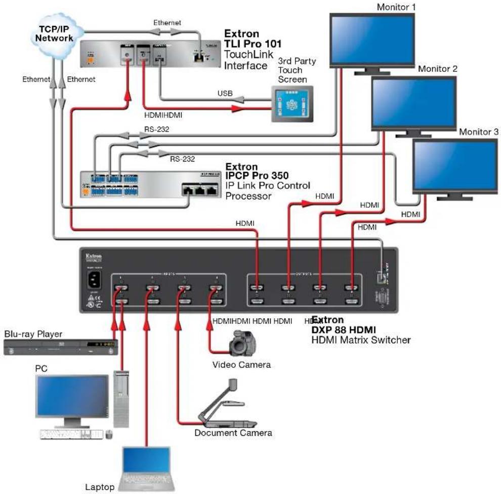
Application Diagram
flowchart
graph TD
    A["TCP/IP Network"] -->|Ethernet| B["Extron TLI Pro 101 TouchLink Interface"]
    B -->|USB| C["3rd Party Touch Screen"]
    C --> D["Monitor 1"]
    C --> E["Monitor 2"]
    C --> F["Monitor 3"]
    B --> G["Extron IPCP Pro 350 IP Link Pro Control Processor"]
    G --> H["HDMI"]
    G --> I["HDMI"]
    G --> J["HDMI"]
    G --> K["HDMI"]
    G --> L["HDMI"]
    G --> M["HDMI"]
    G --> N["HDMI"]
    G --> O["HDMI"]
    G --> P["HDMI"]
    G --> Q["HDMI"]
    G --> R["HDMI"]
    G --> S["HDMI"]
    G --> T["HDMI"]
    G --> U["HDMI"]
    G --> V["HDMI"]
    G --> W["HDMI"]
    G --> X["HDMI"]
    G --> Y["HDMI"]
    G --> Z["HDMI"]
    G --> AA["HDMI"]
    G --> AB["HDMI"]
    G --> AC["HDMI"]
    G --> AD["HDMI"]
    G --> AE["HDMI"]
    G --> AF["HDMI"]
    G --> AG["HDMI"]
    G --> AH["HDMI"]
    G --> AI["HDMI"]
    G --> AJ["HDMI"]
    G --> AK["HDMI"]
    G --> AL["HDMI"]
    G --> AM["HDMI"]
    G --> AN["HDMI"]
    G --> AO["HDMI"]
    G --> AP["HDMI"]
    G --> AQ["HDMI"]
    G --> AR["HDMI"]
    G --> AS["HDMI"]
    G --> AT["HDMI"]
    G --> AU["HDMI"]
    G --> AV["HDMI"]
    G --> AW["HDMI"]
    G --> AX["HDMI"]
    G --> AY["HDMI"]
    G --> AZ["HDMI"]
    G --> BA["HDMI"]
    G --> BB["HDMI"]
    G --> BC["HDMI"]
    G --> BD["HDMI"]
    G --> BE["HDMI"]
    G --> BF["HDMI"]
    G --> BG["HDMI"]
    G --> BH["HDMI"]
    G --> BI["HDMI"]
    G --> BJ["HDMI"]
    G --> BK["HDMI"]
    G --> BL["HDMI"]
    G --> BM["HDMI"]
    G --> BN["HDMI"]
    G --> BO["HDMI"]
    G --> BP["HDMI"]
    G --> BQ["HDMI"]
    G --> BR["HDMI"]
    G --> BS["HDMI"]
    G --> BT["HDMI"]
    G --> BU["HDMI"]
    G --> BV["HDMI"]
    G --> BW["HDMI"]
    G --> BX["HDMI"]
    G --> BY["HDMI"]
    G --> BZ["HDMI"]
    G --> CA["HDMI"]
    G --> CB["HDMI"]
    G --> CC["HDMI"]
    G --> CD["HDMI"]
    G --> CE["HDMI"]
    G --> CF["HDMI"]
    G --> CG["Document Camera"]
    G --> CH["Video Camera"]
    G --> CI["Laptop"]
Figure 1. TLI Pro 101 Application Diagram
Requirements
Software
For a complete list of the requirements for running GUI Designer, Global Configurator Plus and Professional, Global Scripter, or Toolbelt, see the Extron Web page for the appropriate software.
NOTE: The TLI Pro 101 is not compatible with Global Configurator 3 or GUI Configurator.
Hardware
An Extron IP Link Pro control processor must be connected to the same network domain as the TLI Pro 101. See www.extron.com for a list of suitable controllers.
NOTE: The TLI Pro 101 is not compatible with Extron IP Link (non-Pro) control processors.
Installation Overview
- Before starting, download and install the latest versions of the following software:
☐ GUI Designer — for designing layouts for Extron TouchLink Pro touchpanels and third party touch interfaces.
Global Configurator Plus and Professional — for setting up and configuring the control processor and touchpanel.
□ Toolbelt — provides device discovery, device information, firmware updates, and configuration of network settings, system utilities, and user management for TouchLink Pro devices.
Global Scripter — Provides an integrated development environment for Extron control systems programming.
See Configuration Software on page 23.
- Obtain the following network information from your network administrator:
☐ DHCP setting (On or Off). If the DHCP setting is Off, you also need:
□ TLI Pro 101 IP address
□ Subnet mask
□ Gateway IP address
☐ User name — by default these are either admin or user.
☐ Passwords — the factory configured passwords for all accounts on this device have been set to the device serial number. Passwords can be changed during configuration. They are case sensitive.
NOTE: If the device is reset to default settings, the passwords are reset to the default password, which is extron (for either admin or user).
☐ MAC address — make a note of the TLI Pro 101 MAC address.
-
Mount the units. Stand the TLI Pro 101 on a convenient surface, mount it in a standard rack, or use an under-table mounting kit (see Mounting on page 29). To mount the third-party touchpanel follow the instructions provided by the manufacturer.
-
Connect cables to the TLI Pro 101 (see TLI Pro 101 Rear Panel Features and Connections on page 5).
☐ Connect the HDMI output from the TLI Pro 101 (figure 2, Ⓐ on page 5) to the third-party touchpanel.
☐ Connect the USB port from the TLI Pro 10(D) to the third-party touchpanel.
NOTE: The USB connection passes information to the TLI Pro 101 about where on the screen the touchpanel was pressed. To use a normal monitor instead of a touchscreen, connect a mouse to the TLI Pro 101 USB connection. Use the mouse to click on screen icons.
- Connect the power cords and power on all devices (see Power on page 6 or Network and Power over Ethernet (PoE) Connector on page 10).
ATTENTION:
☐ Connect the PC that you will use for setup, the control processor, and the TLI Pro 101 to the same Ethernet subnetwork.
☐ Use the Setup Menu (see page 13) or Toolbelt (see the Toolbelt Help File) to set the DHCP status and, if necessary, the IP address, subnet mask, gateway, and related settings for the interface.
- Configure the Interface — the Global Configurator Professional and Global Configurator Plus Help File and the GUI Designer Help File provide step-by-step instructions and detailed information.
The Global Configurator Professional and Global Configurator Plus Help File includes an introduction to the software and sections on how to start a project and configuration.
Global Scripter provides an Extron-exclusive Python library (ControlScript) and Global Scripter modules to get you started. See the GlobalScripter Help File for more information.
Panel Features, Connections, and Setup
This section describes:
• TLI Pro 101 Rear Panel Features and Connections
• TLI Pro 101 Front Panel Features
TLI Pro 101 Rear Panel Features and Connections

Figure 2. TLI Pro 101 Rear Panel
A Power (see page 6)
B HDMI Input (see page 8)
© HDMI Output (see page 8)
USB Connector (see page 9)
E Network and Power over Ethernet (PoE) Connector (see page 10)
F Reset mode LED (see page 12)
G Reset button (see page 12)
Power (see figure 2, A, on page 5)—Connect the 2-pole, 3.5 mm captive screw connector from the provided 12 VDC power supply to the power supply socket on the rear panel. Figure 3 shows how to wire the connector. Ensure the connections have the correct polarity.
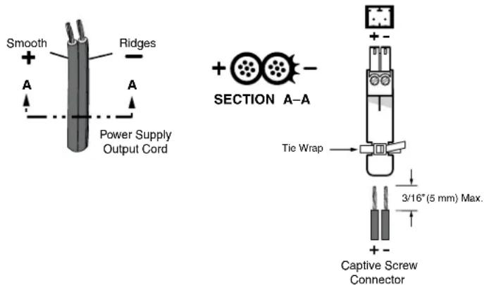
Figure 3. Wiring the Power Connector
WARNING: The two DC output cables must be kept separate from each other while the power supply is plugged in. Remove power before wiring.
CAUTION: Risk of Explosion if the battery is replaced by an incorrect type. Dispose of used batteries according to the Instructions.
- The TLI Pro 101 ships with a 12 VDC, 1.5 A power supply and is also Power over Ethernet (PoE 802.3af, class 3) compliant. The power injector must be purchased separately.
- If a 12 VDC power supply and a PoE power injector are both connected to the TLI Pro 101, the power injector takes precedence. If a PoE power loss is detected, the interface switches seamlessly to the 12 VDC supply without needing a system reboot.
ATTENTION:
B HDMI Input (see figure 2 on page 5) — Plug the cable from the input source device into this female HDMI type A connector. Secure the HDMI connector to the TLI Pro 101
with the provided LockIt HDMI lacing bracket (see "LockIt HDMI Lacing Bracket Installation", below).
The wiring of the connector follows the HDMI single link format. The diagram to the right and the table below show the HDMI pin configuration.

Type A Receptacle
| Pin Signal Pin Signal Pin Signal | ||||
| 1 TMDS data 2+ 7 TMDS data 0+ | 13 CE control | |||
| 2 TMDS data 2 shield 8 TMDS data 0 shield 14 Reserved (NC) | ||||
| 3 TMDS data 2- 9 TMDS data 0- 15 SCL | ||||
| 4 TMDS data 1+ 10 TMDS clock+ | 16 SDA | |||
| 5 TMDS data 1 shield 11 TMDS clock shield 17 DDC/CEC ground | ||||
| 6 TMDS data 1- 12 TMDS clock- | 18 +5 V power | |||
| 19 Hot plug detect | ||||
C HDMI Output — Connect this female HDMI type A connector to a third-party touch screen. A full list of supported Screen Resolutions for video output is shown on the following page.
LockIt HDMI Lacing Bracket Installation:
Secure the HDMI connector to the TLI Pro 101 with the provided LockIt HDMI lacing bracket by following these instructions:
- Plug the source HDMI cable into this input port.
- Loosen the HDMI connection mounting screw from the TLI Pro 101 rear panel enough to allow the LockIt lacing bracket to be placed over it. The screw does not have to be removed.
- Place the Locklt lacing bracket on the screw and against the HDMI connector, then tighten the screw to secure the bracket.
ATTENTION:
Figure 4. Securing the HDMI Connector
- Loosely place the included tie wrap around the HDMI connector and the LockIt lacing bracket as shown.
- While holding the connector securely against the lacing bracket, tighten the tie wrap, then remove any excess length.
Screen Resolutions
| Resolution | 23.98 Hz | 24 Hz | 25 Hz | 29.97 Hz | 30 Hz | 50 Hz | 59.94 Hz | 60 Hz | |
| 800x600 X | |||||||||
| 1024x768 X | |||||||||
| 1280x768 X | |||||||||
| 1280x800 X | |||||||||
| 1280x1024 X | |||||||||
| 1360x768 X | |||||||||
| 1366x768 X | |||||||||
| 1440x900 X | |||||||||
| 1400x1050 X | |||||||||
| 1600x900 X | |||||||||
| 1680x1050 X | |||||||||
| 1600x1200 X | |||||||||
| 1920x1200 X | |||||||||
| 720p XXXXX | |||||||||
| 1080p XXXXXX | |||||||||
| 2048x1080 XXXXXXX | |||||||||
| Custom 1 For new resolutions (field support only) | |||||||||
USB Connector (see figure 2 on page 5) — Supports High-speed USB 2.0 control. Plug a USB cable from the third-party touchpanel into this female type B connector.
The USB connection passes information to the TLI Pro 101 about where on the screen the touchpanel was pressed. To use a normal monitor instead of a touchscreen, connect a mouse to the TLI Pro 101 USB connection. Use the mouse to click screen icons.
E Network and Power over Ethernet Connector (see figure 2 on page 5) —
Connect the interface to the LAN using a twisted pair cable, terminated with an RJ-45 connector. Use a straight-through Ethernet cable to connect the panel to a switch or router. Use a crossover cable to connect the panel directly to a computer.
An Extron IPL Pro Control Processor must also be connected to the same network domain as the interface. See the www.extron.com for a list of suggested models.
The network port has two LEDs. The green LED lights steadily to indicate that the interface is connected correctly to a network. The amber LED blinks to indicate that data is being passed to or from the interface.

Although a 12 VDC, 1.5 A power supply is provided, the
TLI Pro 101 is compliant with the requirements of PoE 8.203af, class 3, which means the unit can be powered by Power over Ethernet. To use Power over Ethernet, connect this port to a PoE power injector (not provided).
ATTENTION:
Use a straight-through Ethernet cable to connect the power injector to a switch or router. This cable carries network information from the switch or router to the power supply input. A second straight-through cable carries the network information and power from the power supply to the TLI Pro 101. Connect the IEC power cord to a convenient 100 VAC to 240 VAC, 50-60 Hz power source.
The figure below shows the Extron XTP PI 100. Your power injector may look different.

Figure 5. Connecting the Power Injector
CAUTION: Risk of Explosion if the battery is replaced by an incorrect type. Dispose of used batteries according to the instructions.
F Reset mode LED (see figure 2 on page 5) — Provides feedback about the reset status when the reset button is pressed (see Reset Modes on page 30).
G Reset button (recessed) — Allows the unit to be reset in any of three different modes (see Reset Modes).
TLI Pro 101 Front Panel Features
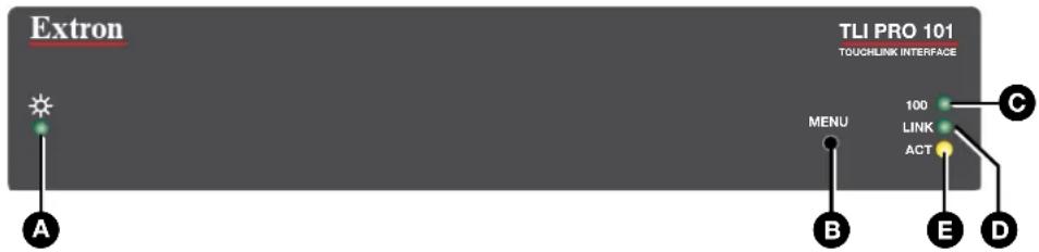
Figure 6. TLI Pro 101 Plus Front Panel
Power LED — Lights when the unit is powered on.
B Menu button (recessed) — Opens the Setup Menu (see the following page) and Calibration Screen (see page 22) for the interface:
Setup Menu
- Press the button briefly (less than 2 seconds) to open the setup menu screens.
- Press the button briefly for a second time to exit the setup menu.
Calibration Screen
- Press and hold the button (at least 3 seconds) to open the calibration screen. Follow the on-screen instructions to calibrate the touchpanel.
- Complete the calibration process or press the button briefly (less than 2 seconds) for a second time to exit the Calibration screen.
C 100 Mb network LED — Lights when the unit is connected to a 100 Mb network.
D Network link LED — Lights when the unit is connected to a network.
E Network activity LED — Flashes when there is activity on the network connection.
On-screen Menus
On-screen menus allow initial configuration of the TLI Pro 101.
- Setup Menu
• Calibration Screen
Setup Menu
To access the setup menus, press the recessed front-panel Menu button (see figure 6, B, on page 12).
The menu opens at the Status screen. There are six different screens (Status, Network, Output, Audio, Input, and Advanced) that can be selected by pressing the appropriate button in the navigation panel at the top of the screen.
There is also a red Exit button in the top right corner of the screen. Pressing this button applies and saves any changes and closes the menu screens.
Status

Figure 7. Status Screen
This is a read-only screen. The Info panel provides basic information about the TLI Pro 101. Each of the other five panels shows a summary of the information on the other screens. Pressing any of the panels opens the corresponding screen in exactly the same way as pressing the buttons in the top navigation panel.
The bubble in the Network panel lights green when there is a network connection or amber if there is no connection. The bubble in the Advanced panel lights green when a control processor is connected or amber if none is connected.
Network
Press the Network button in the navigation panel at the top of the screen to open the Network screen.
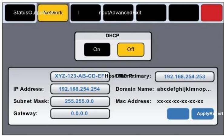
Figure 8. Network Screen
-
If IP addresses are assigned by DHCP, press On. If the IP address is to be assigned manually, press Off.
-
When DHCP is off, the Host Name is grayed out and cannot be edited. All addresses can be edited.
-
When DHCP is on, the Host Name can be edited. The addresses are grayed out and cannot be edited because they are set by the DHCP server.
-
If DHCP is on, press the Host Name button to edit the host name. The Host Name dialog box opens:

Figure 9. Host Name Dialog Box
Use the keypad to enter a new name, which appears in the Host Name text box.
- If DHCP is disabled, set the unit IP address, subnet mask, gateway address, and DNS server address.
a. Press the button for the address to be edited. A dialog box opens, showing the address and a numerical keypad.
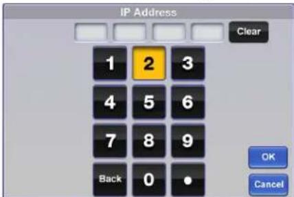
Figure 10. Numeric Pad for Setting IP Addresses
b. Enter the 3-digit value for that octet (leading zeroes in an octet are ignored).
NOTES:
- Octets can have any value between and 255.
- If you attempt to enter an invalid number, for example 892, you are able to enter the 89 but the 2 cannot be entered.
- When a valid 3-digit value is entered, the next octet is automatically selected.
c. Press OK to save the changes and return to the Network screen or press Cancel to return to the Network screen without saving the changes.
- If you have changed any of the values in the Network screen, the background color of the button changes to blue. Press Apply to apply the new values or press Revert to return to the previous values without saving the changes. The button returns to gray. If you have not made any changes, the Apply and Revert buttons are grayed out.
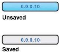
Figure 11. IP Address, unsaved (top) and saved (bottom).
Output
Press the Display button in the navigation panel at the top of the screen to open the Display screen.
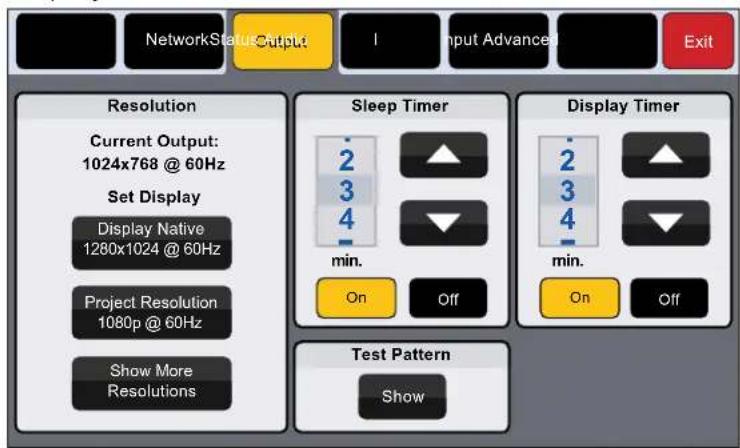
Figure 12. Output Screen
Resolution
The Resolution panel shows the current resolution of the TLI Pro 101 output signal and offers three main options for setting the resolution of the TouchPanel display.
- Click Display Native to set the resolution of the TLI Pro 101 output to the native resolution of the display device.
- Click Project Resolution to use an imported GUI Designer project to set the resolution of the TLI Pro 101 output.
- Click Show More Resolutions for more options:
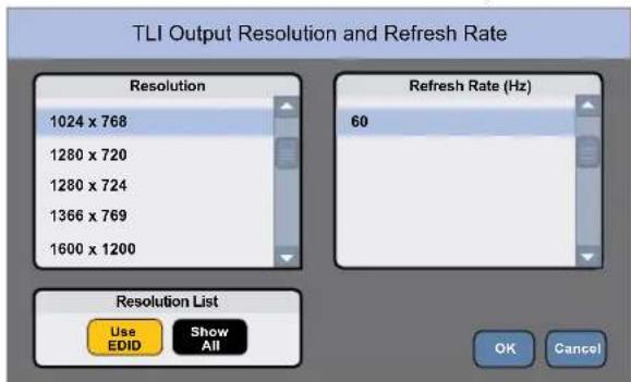
Figure 13. TLI Pro 101 Output Resolution and Refresh Rate
When the panel opens, by default, Use EDID is selected. The resolutions for which EDID files are available are listed on the left. When a resolution is selected, the list of refresh rates available for that resolution can be seen on the right.
Click Show A11 to display all the resolutions and refresh rates supported by the interface (for a complete list, see Screen Resolutions on page 9).
Sleep timer
The Sleep Timer can be toggled between On and Off.
- If the sleep timer is On, after a period of inactivity, the screen goes dark to save power (Sleep mode). Use the up and down arrows to set how long the period of inactivity should be. The value can be between 1 and 120 minutes.
- If the sleep timer is Off, the panel does not enter sleep mode.
Display timer
The Display Timer can be toggled between 0n and Off. If it is 0n, it determines how long the panel is inactive before the output sync is disconnected.
- To deactivate the display timer, click Off. The controls for the Display Timer are grayed out.
- To set the display timer, ensure the function is activated by clicking On. Adjust the time. The value can be between 1 and 120 minutes.
NOTES:
- When the sleep timer is used to deactivate the screen, the screen goes dark, which provides partial energy savings. The screen reactivates quickly when it is touched.
- When the display timer is used to deactivate the screen, the output sync is disconnected and the screen switches off. This provides better energy savings but the screen takes longer to reactivate when it is touched.
Test patterns
The TLI Pro 101 provides eight test patterns, which can be used to calibrate the third-party touchpanel display. Click the Show button to open the test pattern menu.


Figure 14. Test Pattern Menu
- Select the test pattern you need by pressing the icon.
- Swipe the screen from left to right to show the previous test pattern or swipe the screen from right to left to show the next test pattern.
- Touch any part of the screen to show the menu box.
- Click Exit to close the Test Patterns dialog and return to the Output window.
Audio
Press Audio in the navigation panel to open the Audio screen.
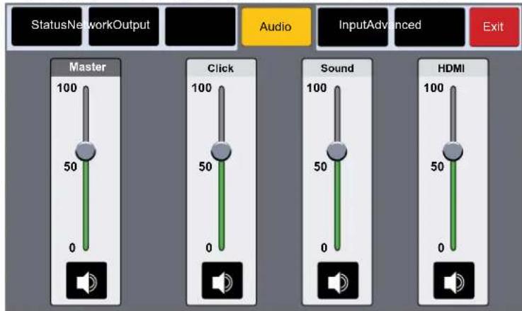
Figure 15. Audio Screen
Use the slider control to adjust the Master, Click, Sound, and HDMI In settings. The slider adjusts the volume setting from 0 to 100% in 1% increments. By default all sliders are set to 80%.
- Master volume sets the maximum volume for all the other sound volume settings. For example, if the master volume is set to 80% (80 percent of maximum), and the the Sound volume is set to 75%, the overall Sound volume is 60% of maximum (75% of 80%).
- Click sets the level for audible feedback that accompanies events such as a screen button being pressed.
• Sound sets the audio level from any audio file playback.
• HDMI sets the HDMI audio input level.
Underneath each slider control is the mute button, which toggles the volume between audio mute and the value set by the corresponding slider. When the Master volume is muted, all other settings (Click, Sound, and HDMI) are also muted.
Input
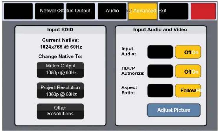
Figure 16. Input Screen
Input EDID
The EDID file is stored by the interface and passed to the video source to ensure that the signal generated by the source is compatible with the display. It determines the resolution and refresh rate of the signal produced by the video source.
Press one of the three Input EDID buttons to determine which EDID will be stored by the interface and passed to the video source:
Match Output (default setting) — The EDID matches the native resolution and refresh rate of the display connected to the HDMI output.
Project Resolution — The EDID is the one set in the GUI Designer project and can be altered only by changing the GUI Designer project file.
Show More Resolutions — Opens a dialog (see figure 15, below) that allows you to select the resolution and refresh rate for the EDID that will be used.

other
Custom EDID | Resolution | Value | | :--- | :--- | | 1024 x 768 | | | 1280 x 1024 | | | 1600 x 1200 | | | 1920 x 1200 | | | 720p | | | Refresh Rate (Hz) | Value | | :--- | :--- | | 23.98 | | | 24 | | | 25 | | | 29.97 | | | 30 | | OK CancelFigure 17. Custom EDID Dialog
- Select the resolution and refresh rate from the lists.
- Click OK to save this EDID or click Cancel to close the dialog without changing the EDID.
Input Audio and Video
The two pairs of buttons on the right of the screen allow three settings to be toggled On and Off.
Input Audio — Enables 2CH PCM support on input EDID. Input Audio is On by default.
HDCP Authorize — When this setting is enabled, HDCP-encrypted input signals pass to the output display. HDCP Authorize is On by default.
Aspect Ratio — Press Fill to stretch the image so that it fills the entire screen. Press Follow for the image to maintain the aspect ratio of the input signal.
Adjust Picture — Press Adjust Picture to open a dialog to adjust the input video picture. Press Brightness,
Contrast, or Detail to adjust those values. Active Pixels and Active Lines are read-only and cannot be edited.
Brightness — ∅ to 127 (default 64)
Contrast — ∅ to 127 (default 64)
Detail — ∅ to 127 (default 64)
Active Pixels (status only)
Active Lines (status only)
Presets — Allows the current values to be saved as a preset and opens the Presets dialog (see figure 16, below).
Default all — Returns the picture values to their default settings.
Exit — Closes the dialog.


flowchart
graph TD
    A["Input Audio:"] --> B["OffOn"]
    C["HDCP Authorize:"] --> D["OffOn"]
    E["Aspect Ratio:"] --> F["FollowFill"]
    G["Adjust Picture"] --> H["End"]
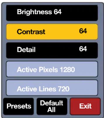
Figure 18. Presets Dialog
Save — Highlight one of the presets and press Save to save the current Brightness, Contrast, and Detail settings to that preset.
Recall — Highlight one of the presets and press Recall to replace the current settings for Brightness, Contrast and Detail with those saved by that preset.
Rename — Highlight one of the presets and press Rename to assign a new name to the preset.
Clear — Highlight one of the presets and press Clear to clear the values stored by that preset.
Advanced
The Advanced window provides additional information about the interface and the GUI Designer project that is uploaded to it.

Figure 19. Advanced Screen
System and GUI Project Panels
These panels are read only, providing information about the system, the Global Configurator Project, and the GUI Designer Project.
Menu PIN
To prevent unauthorized access to the setup menu, users can set a PIN, which is a 4-digit number. Each digit can have any value from 0-9. The PIN setup options allow you to enable, disable, or change the setup menu PIN.
By default, PIN use is disabled.
- Enter a four-digit PIN.

Figure 20. Numeric Keypad for Setting PIN
The title bar changes to Confirm New Menu Pin.
- Enter the PIN a second time. When the PIN entered on the second occasion matches the PIN entered on the first occasion, the PIN is set and the dialog closes.
Calibration Screen

Figure 21. Touch Calibration Screen
- Press and hold down the recessed front-panel Menu button (see figure 6, B, on page 12) for at least 3 seconds.
- Release the button. The calibration screen opens to show cross-hairs (see figure 21, above).
- Press the cross-hairs on the screen until they move to another area of the screen.
- Repeat step 3 until you have pressed all five sets of cross-hairs (one in each corner and one in the center of the screen).
The touchpanel exits the calibration screen once the calibration process is completed.
Configuration Software
This section of the user guide provides information about:
- Configuration Software
• TLI Pro 101 Web Page - Updating the Firmware
Configuration Software
Toolbelt, GUI Designer, Global Configurator Plus and Professional, and Global Scripter can be downloaded from www.extron.com.
NOTES:
- You will need an Extron Insider account to run Global Scripter or Global Configurator Plus and Professional. To obtain one, contact the Extron Sales Department.
- The TLI Pro 101 is not compatible with earlier Extron software (GUI Configurator or Global Configurator 3). Ensure you are downloading GUI Designer and Global Configurator Plus and Professional.

Figure 22. Software Downloads from the Extron Website
- Open www.extron.com and select the Download tab (1).
- Click Software (②)
The Download Center Software page opens:

Figure 23. Selecting Software to Download
- The software may be shown in the panels at the top of the page. Figure 23 (1) shows Global Configurator Plus and Professional.
You may need to use the left (<) or right (>) arrows (②) to find the software. If the software is still not shown, click on the initial letter of the program in the alphabet menu (③).
Downloading software from the product page
Clicking on the panels at the top of the page takes you to the software product page on the Extron website. Figure 24 shows the GCP product page.

Figure 24. GCP Product Page
To download and install the product, click Download (1) and follow the onscreen instructions. The software is downloaded and installed on your PC. By default, the software is saved in a newly created folder: C:\Program Files (x86)\Extron\
Downloading software from the alphabet menu
Clicking on the initial letter of the software product (see figure 23, ③, on the previous page) generates a list of software products with that initial letter.
- Scroll down to the product you wish to download. Figure 25 shows the panel for Toolbelt.

Figure 25. Downloading from the Alphabet Menu
- Click Learn More (①) to go to the software product page.
- Click Release Notes (①) to find out what has been updated in the software since the previous release.
- To download and install the product, click Download (②) and follow the onscreen instructions. By default, the software is saved in a newly created folder: C:\Program Files (x86)\Extron\
.
Using the Software
NOTE: You need an Extron Insider account to run Global Configurator. To obtain one, contact the Extron Sales Department.
Use the appropriate software help file for step-by-step instructions and more detailed information. The Global Configurator Help File also includes an introduction to the software and sections on how to start and configure a project.
Toolbelt
Use Toolbelt to provide device information, firmware updates, certificate management, and configuration of network settings, system utilities (reset, reboot), and user management (username and password) for TouchLink Pro devices.
GUI Designer
Design the layout of the screen text and graphics using GUI Designer, which is a Windows ^® -based application. You can either customize one of several existing templates or create an entirely new interface.
After the user interface has been designed, the project is saved, built, and imported into Global Configurator Plus and Professional or Global Scripter.
Global Configurator Plus and Professional
Use Global Configurator Plus and Professional to assign functions to the screen text and graphics.
After assigning the control functions, the project is rebuilt and uploaded to the control processor and touchpanel.
Global Scripter
You can use Global Scripter as an alternative to GCP. Global Scripter provides an integrated development environment for Extron control systems programming, including an Extron-exclusive Python library (ControlScript) and Global Scripter modules to get you started. See the GlobalScripter Help File for more information.
TLI Pro 101 Web Page
To access the TLI Pro 101 default web page, enter the IP address of the unit into the web browser of a PC connected to the same subnet.
A dialog opens asking for your user name and password.
NOTES:
- The factory configured passwords for all accounts on this device have been set to the device serial number. Passwords can be changed during configuration. They are case sensitive.
- If the device is reset to default settings, the passwords are reset to the default password, which is extron (for either admin or user).
The single page provides general and network information about the unit. It also allows you to upgrade the unit firmware.
Use the Setup Menu (see page 13) or Toolbelt to configure the network settings of the TLI Pro 101.
Extron Electronics

Figure 26. TLI Pro 101 Web Page
Updating the Firmware
Firmware for the TLI Pro 101 can be upgraded using Toolbelt or the TLI Pro 101 web page. Before starting, consult your IT team and ensure that the interface has a unique IP address. To update firmware, first download and run the file from the Extron website. Then use Toolbelt or the TLI Pro 101 web page to upload the file to the touchpanel.
Downloading Firmware Using Extron Firmware Loader
- The firmware must be downloaded to a PC on the same sub-network as the TLI Pro 101.

Figure 27. Firmware Download Center
- Go to www.extron.com and click Download (1).
- Click Firmware (②).
The Download Firmware page opens:
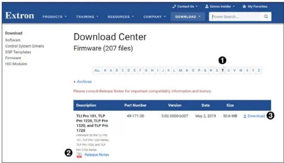
Figure 28. Selecting Firmware to Download.
-
Click the letter T from the list of letters (①).
-
Scroll down the page until you find the firmware for the TLI Pro 101.
NOTE: Your product will appear in this list only if a new version of the firmware has been released since the product was first introduced.
- (Optional) Click Release Notes for more information about the firmware (see figure 28, ②, on the previous page).
- Click Download (3).
- Follow the on-screen instructions to download the program. An executable file is downloaded to the PC.
- Go to the Downloads folder and click on the file to install the firmware on the PC. By default, it is stored at C:\Program Files (x86)\Extron\Firmware\
\ . - Use Toolbelt or the Touchpanel web page to upload this file to the touchpanel (see the Toolbelt Help File or the following section).
Updating Firmware Using the Touchpanel Web Page
- If you have not already done so, download the firmware file to a computer on the same network as the touchpanel (see the previous section).
- Open the TLI Pro 101 Web Page (see page 26).

Figure 29. Touchpanel Web Page: Firmware Uploader
- Click Browse and navigate to the firmware location.
- Click on the file to highlight it.
- Click Upload. The firmware file is uploaded to the touchpanel. Follow the on-screen instructions.
Mounting
This section outlines the various options for mounting the TLI Pro 101.
- Tabletop Placement
- Rack Mounting
• Under-desk Mounting
Tabletop Placement
Attach the four provided rubber feet to the bottom of the unit and place it in any convenient location.
Rack Mounting
Underwriters Laboratories Guidelines for Rack Mounting
The following Underwriters Laboratories (UL) guidelines are relevant to the safe installation of these products in a rack:
Elevated operating ambient temperature — If the unit is installed in a closed or multi-unit rack assembly, the operating ambient temperature of the rack environment may be greater than room ambient temperature. Therefore, install the equipment in an environment compatible with the maximum ambient temperature (Tma: +122 °F, +45 °C) specified by Extron.
Reduced air flow — Install the equipment in the rack so that the equipment gets adequate air flow for safe operation.
Mechanical loading — Mount the equipment in the rack so that uneven mechanical loading does not create a hazardous condition.
Circuit overloading — Connect the equipment to the supply circuit and consider the effect that circuit overloading might have on overcurrent protection and supply wiring. Give appropriate consideration to the equipment nameplate ratings when addressing this concern.
Reliable earthing (grounding) — Maintain reliable grounding of rack-mounted equipment. Pay particular attention to supply connections other than direct connections to the branch circuit (such as the use of power strips).
Rack Mounting the TLI Pro 101
The TLI Pro 101 can be mounted on any Extron standard rack system (not provided). See www.extron.com for a list of appropriate kits and follow the instructions included with the kit.
Under-desk Mounting
Mount the unit under a desk or podium, using an Extron under-desk mounting kit (not provided). See www.extron.com for a list of appropriate kits and follow the instructions included with the kit.
Reference Material
This section describes:
• Network Port Requirements and Licensed Third-party Software Used by the Touchpanels
- Reset Modes
- Secure Sockets Layer (SSL) Certificates
• IEEE 802.1X Certificates
Network Port Requirements and Licensed Third-party Software Used by the Touchpanels
For information about network port requirements and licensed third-party software for all the touchpanels described in this guide, please refer to the Pro Series Control Product Network Ports and Licenses Guide, which is available at www.extron.com.
Reset Modes
The TLI Pro 101 has three reset modes that are initiated by pressing the Reset button:
• Use Factory Firmware
- Reset All IP Settings
- Reset to Factory Defaults
- Enable or Disable the DHCP Client
The Reset button is found on the rear panel (see figure 2, G on page 5).
Use Factory Firmware
This mode is used to boot up the unit with factory-installed firmware for a single power cycle if a firmware update fails or incompatibility issues arise with user-loaded firmware.
Activation
To start the Use Factory Firmware reset mode and replace firmware:
- Remove power from the touchpanel.
-
On the touchpanel, hold down the recessed Reset button (see figure 2, G) while applying power to the unit. When power is restored, the Reset LED (F) lights. Hold the Reset button for a further two seconds before releasing it. The touchpanel enters factory firmware mode.
-
Upload new firmware to the unit as desired (see Updating the Firmware on page 27).
NOTE: Do not continue to operate the touchpanel using the factory firmware version. If you want to use the factory default firmware, you must upload that version again (see Updating the Firmware).
Result
The unit reverts to factory-installed firmware. Event scripting does not start if the unit is powered on in this mode. All user files and settings such as drivers, adjustments, and IP settings are maintained.
NOTE: To return the unit to the firmware version that was running prior to the reset, cycle power to the unit.
Reset All IP Settings
This mode resets all IP settings to factory defaults.
Activation
To reset all IP settings:
- Hold down the Reset button (see figure 2, G on page 5) for about 6 seconds until the Reset LED (F) blinks twice (once at 3 seconds, again at 6 seconds).
- Release and press the Reset button momentarily (for <1 second) within 1 second. Nothing happens if the momentary press does not occur within 1 second.
Result
- Resets All IP Settings mode:
- Sets the IP address back to factory default (192.168.254.251)
- Sets the subnet mask back to factory default (255.255.255.0)
- Sets the gateway address to the factory default ( . . . )
- Sets all other IP settings, addresses, and domain and host names back to factory default
- Turns DHCP off
Reset to Factory Defaults
This mode resets all IP settings and touchpanel settings, including passwords, to factory defaults and removes all configurations. It allows you to start over with configuration and uploading.
NOTES:
- The factory configured passwords for all accounts on this device have been set to the device serial number. Passwords can be changed during configuration. They are case sensitive.
- If the device is reset to default settings, the passwords are reset to the default password, which is extron (for either admin or user).
Activation
To reset the unit to all factory default settings:
- Hold down the Reset button for about 9 seconds until the Reset LED blinks three times (once at 3 seconds, again at 6 seconds, again at 9 seconds).
- Release and press the Reset button momentarily (for <1 second) within 1 second. Nothing happens if the momentary press does not occur within 1 second.
Result
Reset to Factory Defaults mode performs a complete reset to factory defaults (except the firmware).
- Does everything Reset All IP Settings mode does.
- Removes touchpanel user interface layout and configurations.
- Resets all touchpanel settings to factory default.
Enable or Disable the DHCP Client
This mode toggles between DHCP enabled and DHCP disabled. This can also be carried out from the Network screen of the Setup Menu (see page 13) and from the device Network tab in Toolbelt (see the Toolbelt Help File).
Activation
To enable or disable the DHCP client for the LAN port:
- Press the Reset button five times, consecutively (see figure 2, G on page 5).
- Release the button. Do not press the button within 3 seconds, following the fifth press.
Result
- If DHCP was enabled, it is now disabled. The Reset LED ( F) blinks three times.
- If DHCP was disabled, it is now enabled. The Reset LED blinks six times.
NOTES:
- By default DHCP is off and the unit uses a static IP address.
- When you disable DHCP, the unit reverts to using the previously-set static IP address.
Secure Sockets Layer (SSL) Certificates
Extron TouchLink Pro products ship with factory-installed SSL certificates created by Extron. If you want or are required to use a different SSL certificate at your installation site, then you can use system utilities in the Toolbelt software to change the SSL certificate at any time. The Toolbelt Help File provides instructions on how to apply an SSL certificate.
NOTES:
- You must run Toolbelt as an administrator.
- Some certificates require a passphrase that is created when the certificate is created. If a passphrase is required, you must enter that passphrase before uploading and applying the certificate.
These devices support standard OpenSSL certificate encodings such as .pem (Privacy-enhanced Electronic Mail) and .der (Distinguished Encoding Rules) file types. PEM file types are ASCII encoded and are the required format for uploading to the Extron control product. DER file types are binary encoded and can typically have several file extension variations, such as .crt and .cer. There are many standard tools that can convert from DER to PEM file encodings if needed.
NOTE: A DER format file must be converted to PEM encoding before uploading it to the button panel, control processor, or collaboration receiver.
To properly create the certificate for uploading to Extron control devices, ensure that the certificate file meets the following requirements:
• contains X.509 certificate information
• contains public and private keys
- uses PEM encoding
NOTE: ITU-T standard X.509 covers aspects of public key encryption, digital cryptography, certificates, and validation.
Contact your IT administrator for more information on what tools and policies are required to obtain or create the SSL certificate and, if necessary, the corresponding passphrase.
IEEE 802.1X Certificates
IEEE 802.1X is a standard that enables port-based network access control via an authentication server. The protocol requires that all devices must be authenticated before gaining privileges to access the secure part of the network.
The Extron implementation of 802.1X supports PEAP - MSCHAPV2 and EAP - TLS methods of authentication. This section of the guide details the Certificate File Requirements and the Private Key File Requirements to be used in the system.
Extron provides resources for learning about 802.1X implementation:
The Extron 802.1X Technology Reference Guide, available from www.extron.com, is the primary resource for background information, system planning, topology, and how to set up these systems.
The Toolbelt Help File provides detailed step-by-step information on using the software to set up 802.1X for IP Link Pro control systems and on troubleshooting.
The 802.1X Primer white paper, also available from www.extron.com, provides a general overview of the protocol and its use within a control system.
NOTES:
- You must run Toolbelt as an administrator.
• Machine certificates require a private key file, which can be encrypted.
Certificate File Requirements
PEM (Privacy-enhanced Electronic Mail) file types are ASCII encoded, and they are the required format for 802.1X authentication for the TouchLink Pro control systems. DER (Distinguished Encoding Rules) file types are binary encoded and can typically have several file extension variations, such as .crt and .cer.
NOTE: DER encoded files (files with .der, .crt, or .cer extensions that are encoded in DER binary format) must be converted to a PEM encoded file type (.pem) before being used for authentication.
DER encoded certificates must be converted to PEM encoding using a third-party tool.
Contact your IT administrator for more information on required tools.
To create the 802.1X security certificate for uploading to Extron TouchLink Pro control systems, ensure that the certificate file meets the following requirements:
- It contains X.509 certificate information.
- It contains a private key (for machine certificates only).
- It is PEM encoded.
- It has a file extension that is .crt or .pem
- Its file name consists of the following types of valid characters:
• Alphanumerical (A-Z, a-z, 0-9) characters - Some special characters (colon [:], underscore [__], and hyphen [-])
NOTE: Spaces are not permitted anywhere in the name.
Private Key File Requirements
Private key files are required only when employing machine certificates. Follow these requirements for creating a private key:
- Its file name consists of the following types of valid characters:
• Alphanumerical (A-Z, a-z, 0-9) characters - Some special characters (colon [:], underscore [_], and hyphen [-])
- It has a file extension that is .key or .pem.
- It can have optional encryption (via password or passphrase).
Extron Warranty
Extron Electronics warrants this product against defects in materials and workmanship for a period of three years from the date of purchase. In the event of malfunction during the warranty period attributable directly to faulty workmanship and/or materials, Extron Electronics will, at its option, repair or replace said products or components, to whatever extent it shall deem necessary to restore said product to proper operating condition, provided that it is returned within the warranty period, with proof of purchase and description of malfunction to:
USA, Canada, South America, and Central America:
Extron Electronics
1230 South Lewis Street
Anaheim, CA 92805
U.S.A.
Asia:
Extron Electronics Asia Pte. Ltd.
135 Joo Seng Road, #04-01
PM Industrial Bldg.
Singapore 368363
Singapore
Japan:
Extron Electronics, Japan
Kyodo Building, 16 Ichibancho
Chiyoda-ku, Tokyo 102-0082
Japan
Europe:
Extron Europe
Hanzeboulevard 10
3825 PH Amersfoort
The Netherlands
China:
Extron China
686 Ronghua Road
Songjiang District
Shanghai 201611
China
Middle East:
Extron Middle East
Dubai Airport Free Zone
F13, PO Box 293666
Dubai, United Arab Emirates
Africa:
Extron South Africa
South Tower
160 Jan Smuts Avenue
Rosebank 2196, South Africa
This Limited Warranty does not apply if the fault has been caused by misuse, improper handling care, electrical or mechanical abuse, abnormal operating conditions, or if modifications were made to the product that were not authorized by Extron.
NOTE: If a product is defective, please call Extron and ask for an Application Engineer to receive an RA (Return Authorization) number. This will begin the repair process.
USA: 714.491.1500 or 800.633.9876 Asia: 65.6383.4400
Europe: 31.33.453.4040 or 800.3987.6673 Japan: 81.3.3511.7655
Africa: 27.11.447.6162 Middle East: 971.4.299.1800
Units must be returned insured, with shipping charges prepaid. If not insured, you assume the risk of loss or damage during shipment. Returned units must include the serial number and a description of the problem, as well as the name of the person to contact in case there are any questions.
Extron Electronics makes no further warranties either expressed or implied with respect to the product and its quality, performance, merchantability, or fitness for any particular use. In no event will Extron Electronics be liable for direct, indirect, or consequential damages resulting from any defect in this product even if Extron Electronics has been advised of such damage.
Please note that laws vary from state to state and country to country, and that some provisions of this warranty may not apply to you.


- Safety Instructions • English
- Battery Notice
- Trademarks
- Conventions Used in this Guide
- Notifications
- Software Commands
- Specifications Availability
- Extron Glossary of Terms
- Contents
- Introduction....1
- Installation Overview......3
- Panel Features, Connections, and Setup....5
- On-screen Menus....13
- Configuration Software....23
- Mounting 29
- Reference Material....30
- Introduction
- About the TLI Pro 101
- Features
- Application Diagram
- Requirements
- Software
- Hardware
- Installation Overview
- ATTENTION:
- Panel Features, Connections, and Setup
- LockIt HDMI Lacing Bracket Installation:
- E Network and Power over Ethernet Connector (see figure 2 on page 5) —
- TLI Pro 101 Front Panel Features
- Setup Menu
- Calibration Screen
- On-screen Menus
- Status
- Network
- NOTES:
- Output
- Resolution
- Sleep timer
- Display timer
- Test patterns
- Audio
- Input
- Input EDID
- Input Audio and Video
- Advanced
- System and GUI Project Panels
- Menu PIN
- Configuration Software
- Downloading software from the product page
- Downloading software from the alphabet menu
- Using the Software
- Toolbelt
- GUI Designer
- Global Configurator Plus and Professional
- Global Scripter
- TLI Pro 101 Web Page
- Extron Electronics
- Updating the Firmware
- Downloading Firmware Using Extron Firmware Loader
- Updating Firmware Using the Touchpanel Web Page
- Mounting
- Tabletop Placement
- Rack Mounting
- Underwriters Laboratories Guidelines for Rack Mounting
- Rack Mounting the TLI Pro 101
- Under-desk Mounting
- Reference Material
- Network Port Requirements and Licensed Third-party Software Used by the Touchpanels
- Reset Modes
- Use Factory Firmware
- Activation
- Result
- Reset All IP Settings
- Reset to Factory Defaults
- Enable or Disable the DHCP Client
- Secure Sockets Layer (SSL) Certificates
- IEEE 802.1X Certificates
- Certificate File Requirements
- Private Key File Requirements
- Extron Warranty
- USA, Canada, South America, and Central America:
- Asia:
- Japan:
- Europe:
- China:
- Middle East:
- Africa:
Brand : Extron
Model : TLI Pro 101
Category : Electronic controller