
M5000 - Monitor SIMRAD - Free user manual and instructions
Find the device manual for free M5000 SIMRAD in PDF.


| Product Type | Marine Graphic Monitor |
| Brand | Simrad |
| Model | M5000 |
| Display Size | 5.7 inches (diagonal) |
| Display Type | LCD, Color |
| Resolution | 640 × 480 pixels |
| Brightness | 1000 nits (sunlight readable) |
| Power Supply | 12 V DC (10–18 V range), 15 W |
| Dimensions (W × H × D) | 200 × 150 × 65 mm (7.9 × 5.9 × 2.6 in) |
| Weight | 1.2 kg (2.6 lbs) |
| Mounting | Flush or bracket mount |
| Water Resistance | IPX6 (protected against powerful water jets) |
| Operating Temperature | -15°C to +55°C (5°F to 131°F) |
| Video Input | 1× composite video (BNC) |
| NMEA Interface | NMEA 2000 / NMEA 0183 |
| Key Functions | Depth, speed, temperature, heading display |
| Alarms | Depth, anchor, waypoint arrival, engine |
| Clean Screen | Soft cloth with mild detergent; avoid abrasives |
| Serviceable Parts | Fuse, mounting bracket (field replaceable) |
| Repairability | Professional service recommended |
Frequently Asked Questions - M5000 SIMRAD
User questions about M5000 SIMRAD
0 question about this device. Answer the ones you know or ask your own.
Ask a new question about this device
Download the instructions for your Monitor in PDF format for free! Find your manual M5000 - SIMRAD and take your electronic device back in hand. On this page are published all the documents necessary for the use of your device. M5000 by SIMRAD.
USER MANUAL M5000 SIMRAD
M5000 Series Monitors
User Guide
ENGLISH
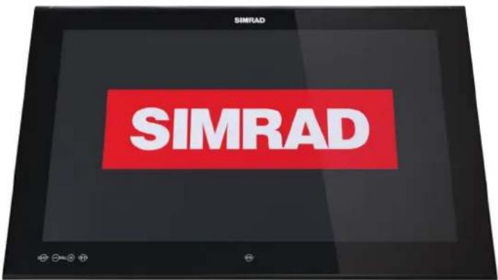
Preface
As Navico is continuously improving this product, we retain the right to make changes to the product at any time which may not be reflected in this version of the manual. Please contact your nearest distributor if you require any further assistance.
It is the owner's sole responsibility to install and use the equipment in a manner that will not cause accidents, personal injury or property damage. The user of this product is solely responsible for observing safe boating practices.
NAVICO HOLDING AS AND ITS SUBSIDIARIES, BRANCHES AND AFFILIATES DISCLAIM ALL LIABILITY FOR ANY USE OF THIS PRODUCT IN A WAY THAT MAY CAUSE ACCIDENTS, DAMAGE OR THAT MAY VIOLATE THE LAW.
Governing Language: This statement, any instruction manuals, user guides and other information relating to the product (Documentation) may be translated to, or has been translated from, another language (Translation). In the event of any conflict between any Translation of the Documentation, the English language version of the Documentation will be the official version of the Documentation.
This manual represents the product as at the time of printing. Navico Holding AS and its subsidiaries, branches and affiliates reserve the right to make changes to specifications without notice.
Copyright
Copyright © 2016 Navico Holding AS.
Warranty
The warranty card is supplied as a separate document.
In case of any queries, refer to the brand web site of your display or system: www.navico.com/commercial
Compliance Statements
The M5000 series monitors complies with:
• IEC 60945 (2002)
• IEC 62288 edition 1 (2008)
• IEC 62288 edition 2 (2014)
- IEC 60174
The relevant Declaration of Conformity is available in the following website under model documentation section: www.navico.com/commercial

xxx/xx
The Wheelmark
The Marine Equipment Directive 96/98/EC (MED), applies to all new ships, to existing ships not previously carrying such equipment, and to ships having their equipment replaced for ships flying EU or EFTA flags.
This means that all system components covered by annex A1 must be type-approved accordingly and must carry the Wheelmark, which is a symbol of conformity with the Marine Equipment Directive.
The M5000 Series (M5016, M5019, M5024 and M5027) monitors comply with IEC62388 Ed.2 for Radars. The monitors can be used as part of a radar system applying for type approval.
The M5024 and M5027 monitors are color calibrated according to ECDIS requirements (IHO S-52). Only the M5024 and M5027 monitors can therefore be used as part of an ECDIS system applying for type approval.
→ Note: The monitors only comply with the Marine Equipment Directive as part of a type approved system, not as stand-alone units.
Navico has no responsibility for incorrect installation or use of the monitor, so it is essential for the installer to be familiar with the relevant requirements as well as with the contents of the manuals, which covers correct installation and use.
Trademarks
• NMEA 2000 is a registered trademark of the National Marine Electronics Association
- B&G, Simrad, StructureScan, Navico, SonicHub, SimNet, Skimmer, InsightHD, Broadband Radar and Broadband Sonar are trademarks of Navico, registered in the US and other countries
- The terms HDMI and HDMI High-Definition Multimedia Interface, and the HDMI Logo are trademarks or registered trademarks of HDMI Licensing LLC in the United States and other countries
About this manual
This manual is a reference guide for installing and operating the Simrad M5000 Series monitors.
Important text that requires special attention from the reader is emphasized as follows:
→ Note: Used to draw the reader's attention to a comment or some important information.
▲ Warning: Used when it is necessary to warn personnel that they should proceed carefully to prevent risk of injury and/or damage to equipment/personnel.
Contents
6 Introduction
6 Items included
7 Installation
7 Cutout template
8 Fixing options
8 Flush-mounting the display
11 VESA mounting the display
12 Connecting the display
12 Rear connections
12 Cable retention
13 Connecting power
14 Color calibration connection for MARIS ECDIS900 MK5 PC
14 Serial connection using the CT&A cable
15 Operating the display
15 First time operation
16 OSD menu
18 Cleaning and maintenance
18 Display removal
18 Replacing the gasket
19 Replacing the filters
19 Other maintenance
19 Checking current firmware version
19 Installing an update
20 Troubleshooting
21 Accessories
22 Specifications
23 Dimensional drawings
1
Introduction
The Simrad M5000 series monitors offer a low profile solution for displaying video from a variety of sources. This includes 4 models; M5016, M5019, M5024 and M5027.
• The whole M5000 series range complies with IEC62388 for Radars.
- The M5024 and M5027 monitors are color calibrated according to ECDIS requirements. The monitors can be used as part of a type approved ECDIS system.
Note: A color calibrated monitor used in an ECDIS system should be regularly tested to detect the stage at which the display can no longer be used to discriminate important features by color. Refer to the color verification process in your ECDIS documentation.
Items included
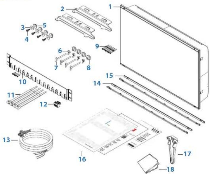
1 Monitor
2 Dash mount brackets (x2)
3 Washer, M4, 12 mm, SS (x4)
4 Phillips pan head machine screw, M4 x 12 mm, SS (x4)
5 Plastic spacer (x4)
6 Wing nut M5 (x4)
7 Wing head machine screw (x4)
8 Plastic stopper - dash mount (x4)
9 Phillips pan head self-tapping screws 4G x 1/2"
10 Cable retention bracket with screws 4G x 1/2" (x4)
11 Cable ties (x4)
12 Connector block (serial data)
13 Power cable with connector
14 Bezel trim, black (x2)
15 Bezel trim, silver (x2)
16 User manual, Cut-out template and Warranty card
17 Drill and screw guide tool
18 Microfiber cleaning cloth
2
Installation
It is recommended that the unit be powered and connected to a video source to assist in selecting a suitable mounting location, prior to irreversible modification of the vessel's helm station. When planning the monitor location, the following points should be considered to ensure safe, comfortable and reliable operation:
- Convenience - the mounting location should be easily accessible to allow operation of the controls and should enable easy viewing of the monitor.
- Viewing distance - the monitor is designed with a nominal viewing distance of 1 meter (3 ft).
- Access - there must be sufficient space behind the monitor to allow cable connections to the rear connectors, avoiding tight bends in the cable. Also ensure there is sufficient access for tightening wing nuts/screws on the mounting brackets, where used.
- Interference - the selected location should be far enough away from devices that may cause interference, such as motors, generators and radio transmitters/receivers.
- Compass safe distance -
| 16" monitors 19" monitors 24" monitors 27" monitors | |
| Standard compass 1.90 m (6.3 ft) 2.00 m (6.6 ft) 2.30 m (7.6 ft) 1.4 m (4.6 ft) | |
| Steering compass 1.10 m (3.7 ft) 1.10 m (3.7 ft) 1.20 m (4.0 ft) 0.75 m (2.4 ft) | |
- Environment - to prevent overheating, do not restrict airflow at the rear of the monitor; ensure that there is adequate ventilation, particularly if the monitor is pod-mounted. If the space behind the monitor is air conditioned or cooled by a fan, it will help in keeping the unit's temperature down. The monitors are designed to operate in protected environments, however, we recommend the units not be mounted in a location where they will be exposed to direct sunlight for prolonged periods.
The monitor should be protected from physical damage and excessive vibration. Although the monitor is waterproof from the front when installed correctly, it is good practice to mount it in a protected area away from prolonged and direct exposure to rain and salt spray.
→ Note: Where flush mounted, the enclosure should be dry and well ventilated. The ventilation of the space behind the unit should be enough to prevent excessive heat build up as a combined result of radiated heat off the monitor, and sunlight heating of the enclosure. In very small enclosures, it may be required to fit forced cooling.
⚠ Warning: Inadequate ventilation and subsequent overheating of display may cause unreliable operation and reduced service life. Ensure enclosure does not consistently exceed +55°C (+131°F) during normal daytime operation (in direct sunlight, and at full screen brightness).
Cutout template
Use the supplied scale template to help mark up the cutout area.
→ Note: Always check the template dimensions against the physical monitor to ensure dimensions are correct, prior to making the cutout.
Fixing options
The M5000 series monitors can be dash or bracket mounted (using optional VESA adaptor). When dash mounting, unit should be fitted using the rear mounted dash mount brackets, and bezel screws from the front. Exclusion of the dash mount bracket will increase strain on bezel screws and adjacent bezel plastics, and is not recommended.
→ Note: The VESA adaptor fixing option is NOT tested against IEC 60945. Monitors that are part of a type approved system can therefore NOT use the VESA bracket mounting option.
Flush-mounting the display
→ Note: The following guidelines and warnings apply:

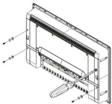
- Fit the supplied M4 machine screws, washers, and plastic spacers to each of the four threaded fittings on the back case of screen. Hand tighten only.
-
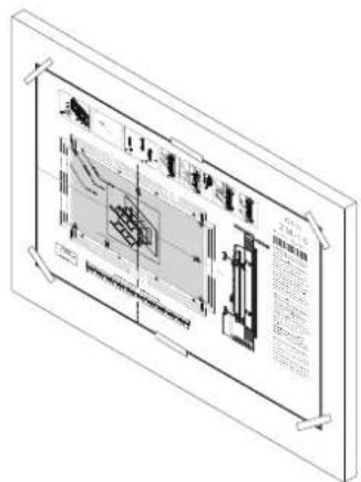
Tape appropriate mounting template in place on dash, and ensure cutout lines are level relative to a reference point on dash.
-
Drill cutout corners with a small pilot drill bit followed with 13 mm drill bit. Complete cutout with jigsaw or similar tool.
→ Note: It is recommended to drill the screw pilot holes using the drill and screw guide tool included in the box.
- Place the display in the dash hole.
- Place the guide tool on the glass of the display.
- Slide the tool across so the drill bit hole guide lines up with the center of a screw location hole on the case of the display.
- Drill the pilot hole.

natural_image
Technical line drawing of a mechanical assembly with an inset showing a close-up of a component (no text or symbols present)→ Note: Before drilling the rest of the pilot holes it is recommended to secure the display with at least one screw to allow for movement in the dash cutout.
- Insert one of the supplied screws in to the screw guide and tighten using a hand screw driver.

natural_image
Technical line drawing of a mechanical assembly with a magnified inset showing a close-up of a component (no text or symbols present)- Repeat for the rest of the mounting screws.

natural_image
Technical line drawings of mechanical components including a bracket and a vertical plate assembly (no text or symbols)- Wind wing nut on to wing screw, then wind the wing screw assembly in to bracket till approximately 5 mm of threaded rod protrudes through other side of bracket.
- Fit stopper foot on to end of wing screw.
-
Complete for both threaded holes on each bracket.
-
Fit brackets to rear of display, aligning 'key holes' on bracket with screws on back of display case.

natural_image
Technical line drawing of a mechanical assembly with no visible text or symbols
- With bracket making contact with back of monitor, slide bracket down till it engages with a click and is held in place.
→ Note: Not applicable for M5027 monitor.
-
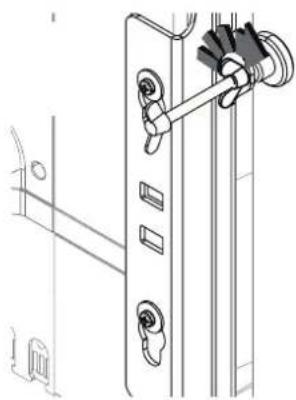
Wind in the wing screw, until stoppers make firm contact with rear of dashboard material.
-
Check front of unit, ensuring that unit's bezel is making even contact with the dash surface.
natural_image
Technical line drawing of a door handle assembly with mounting holes and a lever mechanism (no text or symbols)
natural_image
Technical line drawing of a mechanical assembly with no visible text or symbols-
Hand tighten wing nuts against the back of the mounting brackets to lock the wing screw in place. Hold wing screw stationary if it turns while adjusting the wingnut.
-
When fitting bezels, ensure hook tabs on back of each bezel recess into opposing slots on screen frame. Once flush with front surface of screen, slide top bezel to the left, and bottom bezel to the right to lock in to place.

natural_image
Pure technical diagram of a mechanical assembly with no text, numbers, or symbolsVESA mounting the display
→ Note: The VESA adaptor fixing option is NOT tested against IEC 60945. Monitors that are part of a type approved system can therefore NOT use the VESA bracket mounting option.
VESA bracket adaptor is available as an optional part for all display sizes, allowing a variety of wall and free standing bracket mounting options. The fasteners for attachment to the display are included with the bracket.
Monitors mounted using a Vesa bracket should be mounted in an area sheltered from rain and sea spray.
→ Note: For IPX rating refer to "Specifications" on page 22.

natural_image
Technical line drawing of an electronic device chassis with labeled ports and connectors (no text or symbols present)→ Note: Tilting the monitor forward by more than 15 degrees compromises the IPX2 rating. In fully enclosed helm stations, this limitation may be disregarded.
→ Note: The bracket mounting points on the monitor are only intended to carry the weight of the monitor - do not install monitor in such a place where it may be used as a handhold, or have additional equipment attached to it.
3
Connecting the display
The M5000 series monitors largely use industry standard cables, which can be purchased pre-terminated in a variety of lengths. The following chapter provides additional detail where cables require field termination by the installer.
Rear connections
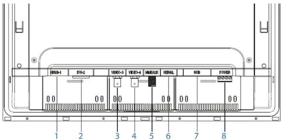
| Key Connection Function | |
| 1 HDMI-1 Video input (digital) | |
| 2 DVI-2 Video input (digital) | |
| 3 VIDEO-3 Video input for camera (composite - analogue) | |
| 4 VIDEO-4 Video input for camera (composite - analogue) | |
| 5 NMEA2K Control input/output, software upgrade | |
| 6 SERIAL Color calibration (used by some systems only) | |
| 7 USB NOT USED | |
| 8 POWER 12/24 V DC power supply input | |
→ Note: HDMI-1, and DVI-2 inputs do not support HDCP (High bandwidth Digital Content Protection). Sources such as protected DVDs may not display correctly/at all on this monitor.
⚠ Warning: Make sure power is switched off before commencing with installation.
Cable retention
Cables fitted to the display should utilize some form of strain relief. All displays are supplied with a retention bracket, which should be attached to the rear case.

natural_image
Technical line drawing of a rectangular electronic component with internal channels and mounting holes (no text or symbols)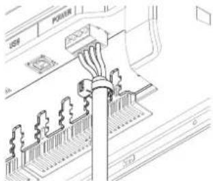
natural_image
Technical line drawing of a mechanical assembly with no visible text or symbolsWith the cable and plug fitted in place, secure the cable to the retention bracket using a cable tie. Do not secure in such a way that applies strain to the cable, or causes the plug or socket to be bent out of alignment.
Connecting power

| Key Color Function | |
| 1 Yellow Power control | |
| 2 Green Chassis ground | |
| 3 Red Positive DC supply (12 V or 24 V system) | |
| 4 Black Negative DC supply (12 V or 24 V system) | |
| 5 Fuse - see table at end of section | |
| 6 DC supply | |
→ Note: This display is not intended for use vessels fitted with a positive ground electrical system. The power input cable screen drain wire should be connected to a negative ground.
→ Note: Chassis ground will typically not be required. In certain problematic installations it may help stabilize touch screen sensitivity, i.e. prevent 'false' touches, or non-registered touches.
→ Note: In an ECDIS configuration connect the red and yellow wires in parallel.
| Recommended fuse rating | ||||
| Model | M5016 | M5019 | M5024 | M5027 |
| Fuse | 3 amp | 4 amp | 4 amp | 4 amps |
Color calibration connection for MARIS ECDIS900 MK5 PC
The M5000 series monitors support color calibration and brilliance control from the MARIS ECDIS900 MK5 PC system. The connection must be made using the CT&A cable.
Serial connection using the CT&A cable
The M5000 series monitors must always be connected to the MARIS ECDIS900 MK5 PC via serial. Make all connections with power turned off.

| Key Function CT&A serial cable colors | |
| 1 RX+ yellow | |
| 2 RX- red | |
| 3 TX+ green | |
| 4 TX- blue | |
| 5 CT&A cable | |
4
Operating the display
The display is configured and controlled using the row of touch sensitive buttons along the lower edge of the monitor frame. All buttons are backlit - only the power button is illuminated when the monitor is turned off.

| Key Description | |
| 1 ON/OFF key- Press to return to previous menu level when the OSD menu is active- Press and hold (2 seconds) to turn the unit ON/OFF | |
| 2 BRILLIANCE adjustment keys- Press minus key to decrease brightness and plus key to increase it (no on-screen display of brightness level)- Press minus key to move cursor down and plus key to move it up when OSD menu is activate- Simultaneously press and hold (2 seconds) both keys to reset the brightness level to default value. The default value is set in the OSD menu * | |
| 3 ENTER key- Press to confirm a selection when operating the OSD menu | |
| 4 Red LED- Solid red = 'active off' (no video source)- Flashing = booting or upgrading | |
| 5 Menu key- Press and hold (2 seconds) to activate the OSD menu |
* Not applicable for ECDIS where the default values for brilliance, contrast and colour temperature are set according to the calibrated values for current active palette.
First time operation
The display has the capability to automatically adjust itself to the resolution of the source to which it is attached. This auto adjustment will take place when the unit is first installed and connected to a source and there after, if the video input changes, or is user initiated.
OSD menu
This menu accesses controls for all aspects of picture setup, and is accessed by pressing and holding the Menu key for 2 seconds when the monitor is on. The main menu options are explained in the following:
| Option Sub option Range Function | |||
| Display | Brightness | 0-100 | Adjusts backlighting level |
| Default Brightness | Sets the default brightness, activated by pressing the Minus/Plus keys simultaneously when the OSD is not displayed | ||
| Contrast | Adjusts image contrast (range between darkest and lightest) | ||
| Hue(analogue video only) | Shifts colors represented by screen | ||
| Saturation(analogue video only) | Varies colour intensity, from dull to full and rich | ||
| Option Sub option Setting Function | |||
| Scaling | HDMI-1 | 1:1, FILL, ASPECT | Sets input image to true size, fill available screen area, or to fill screen vertically or horizontally but maintain correct aspect ratio |
| DVI-2 | |||
| VID-3 | |||
| VID-4 | |||
| Option Sub option Setting/ | Range | Description | |
| PIP Control (Picture-in-Picture) | PIP Mode | OFF, PIP, Split | Sets to either no PIP, regular PIP as dictated by following settings, or 50:50 split pane (image scaled to fit) |
| PIP Swap Swaps | main source | with PIP source | |
| PIP Size | Small, Medium, Large | Controls PIP window size. Sets screen area to: small: 409 x 240 pixels medium: 555 x 312 pixels large: 683 x 384 pixels | |
| PIP Horizontal | 0-100 | Adjusts horizontal position, where 0 = left, and 100 = right | |
| PIP Vertical | 0-100 | Adjusts vertical position, where 0 = bottom, and 100 = top | |
| Option Sub option Setting/Range Description | |||
| Source | Main Source | HDMI-1, DVI-2, VID-3, VID-4 | Select which physical input should be displayedNote: PIP source can only be set to VID-3 or VID-4 when HDMI or DVI are the main source. The reverse applies when either of the analogue sources is set as main source |
| PIP Source | |||
| Option Sub option Range Description | |||
| OSD Position | Horizontal | 0-100 | Adjusts horizontal position, where 0 = left, and 100 = right |
| Vertical | Adjusts vertical position, where 0 = left, and 100 = right | ||
| Option Sub option Description | ||
| Language | EnglishFrenchGermanSpanishItalianPortuguese | Select language for OSD text |
| Option Sub option Range Description | |||
| Configuration | Power Control | Slave, Master | In slave mode monitor will turn on if 12/24 V is detected on the yellow wire. In master mode monitor will turn on slave devices by switching 12 V to yellow wire when monitor is on |
| Key Beeps Off, On Turns on or off the OSD key beeps | |||
| Factory Reset Yes, No Restore all settings to default | |||
5
Cleaning and maintenance
If the display requires cleaning, use a damp soft cloth (e.g. microfiber) with a mild, non-abrasive glass cleaner. Ensure cloth is regularly washed or replaced.
→ Note: Do not use paper products as they may scratch the surface. To minimize the risk of abrasion, allow the screen to air dry.
→ Note: Never use acidic, ammonia based, or abrasive cleaning products to clean the display. These products will damage special coatings on the glass.
→ Note: To prevent damage caused by lightning strikes, it is recommended to disconnect the display from the power source during intense storms, or when the product is not in use for extended periods.
Display removal
The display's top and bottom bezel trim must be removed in order to undo the fasteners holding unit in place by the mounting flange. The bezel trim have been designed to be very low profile, and therefore fully conceal the locking tabs that keep them from being accidentally disengaged from the mounting flange. To release the locking tab, it is necessary to gently lever the centre of the bezel trim away from the mounting flange. To remove the cover, simultaneously slide it sideways; to the right for the top cover, and to the left for the bottom cover.

natural_image
Isometric diagram of a rectangular panel with directional arrows indicating movement or force (no text or symbols)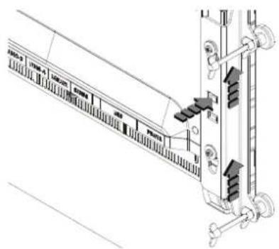
The mounting brackets should be loosened in reverse order to fitting. To remove the brackets, depress the locking tab before sliding brackets upwards.
Replacing the gasket
The foam gasket on the rear of the display bezel is available as an optional accessory, should the factory installed item be damaged.

natural_image
Technical diagram of an electrical connector assembly with internal components and directional arrows (no text or labels)Fit the two lengths of foam gasket in to the rebated channel on the back of the displays mounting flange. Only remove backing paper from the side to be stuck to monitor, and only remove a small amount at a time. Ensure the gasket ends of the two halves overlap and make contact.
→ Note: Take care not to stretch gasket when applying. Only pull gasket minimum amount required to lay it on straight. The backing paper on outside of gasket will help prevent stretch, and should only be removed when display is ready to install in to dashboard.
Replacing the filters
Where displays are installed in an unsealed enclosure, air intake filters should be inspected yearly, and replaced if noticeably fouled. If vessel is subject to major works involving spray painting or sanding, it is recommended that the monitor either be removed, or completely covered in a clean fabric drop cloth.
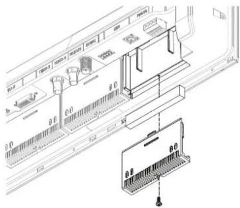
→ Note: M5016 and M5019 models require three filter elements. The filter accessory kit includes five elements.
Other maintenance
Only qualified service personnel should perform any repairs that require opening of the case.
⚠ Warning: Some components in the display unit operate on high voltages. Repairs require specialized service procedures and tools only available to service technicians - there are no user serviceable parts or adjustments. The operator should never remove the display unit cover or attempt to service the equipment. Any attempt to do so may make the warranty invalid.
Updating the firmware
Updates to the M5000 series monitor firmware may occasionally become available. The updates will typically include improvements to existing functionality or new features, and will be made available via the Simrad PRO website: www.navico.com/commercial
Checking current firmware version
On the Configuration page it is possible to see the name of the monitor, resolution (native), OSD version, BIOS version, and the serial number.
Installing an update
Updates should be loaded via a compatible Simrad device such as the NSO evo2. Refer to the applicable product manual on how to upgrade a device over NMEA 2000.
Alternatively, return the device to a Navico dealer to arrange updating.
→ Note: We do not recommend updating more than two displays at the same time. Do not update the display being used to monitor the update status. In the rare occurrence the update fails, the LED indicator will flash and nothing will be visible on the screen.
6
Troubleshooting
| Issue Possible Cause | |
| No picture - red LED ON | LED on continuously indicates no (compatible) video is available on currently selected source;Confirm that the correct video input is selectedCheck that the video signal cable is properly connected to the display. Test cable with 'known good' equipmentCheck display settings of the video source - ensure the resolution is supported by the displayEnsure brightness is turned up to a suitable level |
| No picture - red LED flashing | Flashing LED indicates there is no ground connection detected. |
| No picture - red LED OFF | Make sure power is connected to an appropriate DC voltage source, and that the fuse is fitted or breaker is switched on. After pressing power button, the red LED should blink as monitor starts up, followed by momentary display of the logo on the screen. Make sure brightness level is set to a suitable level. |
| Image persistence | Image persistence occurs when a ghost of an image remains on the screen after the screen image has been changed. Unlike a CRT monitor, an LCD monitor's image persistence is not permanent. To erase an image ghost, turn the monitor off for several hours. To avoid this condition, do not leave the monitor displaying the same image unnecessarily, for an extended period of time |
| Picture quality & image stability | Check for video cable condition; is shield intact, and does cable not exceed maximum distance for video standardCheck the signal source is outputting a compatible resolution at a supported frequencyMonitor may be receiving incorrect/bad sync signals from sourceVideo compromised by interference from other equipment |
| Low level backlight | Supply voltage has dropped below 10 V. Will restore at >11 VUnit has been subject to excessively hot direct sunlight for an extended period and/or unit enclosure is too hot. Automatic thermal protection has been enabled |
| Slight distortion in text or graphics | Not working in native resolution, where possible adjust the video source to output correct resolution |
| Display is present but "bars" appear or roll across screen | Ground loop problem between video source and monitorVideo compromised by interference from other equipment |
| Vertical shaded bars on screen image | Incoming video may be in 4:3 ratio, either leave in 'aspect' mode, or set to 'fill' to use full screen space. |
7
Accessories
| Part description Part number | |
| M5016 bezel trim, silver and black (4 pieces) 000-11620-001 | |
| M5019 bezel trim, silver and black (4 pieces) 000-11621-001 | |
| M5024 bezel trim, silver and black (4 pieces) 000-11622-001 | |
| M5027 bezel trim, silver and black (4 pieces) 000-13550-001 | |
| M5016 Vesa bracket 000-11615-001 | |
| M5019 Vesa bracket 000-11616-001 | |
| M5024 Vesa bracket 000-11617-001 | |
| M5027 Vesa bracket 000-13548-001 | |
| M5027 Gimbal bracket kit 000-13547-001 | |
| Cable retention bracket (all models), includes 4 cable ties, screws 000-11614-001 | |
| M5016/19/24/27 rear mounting kit 000-11618-001 | |
| M5016/19/24 dash seal kit (6 pieces) 000-11619-001 | |
| M5027 dash seal kit 000-13549-001 | |
| M5016/19/24/27 inlet filters (5 pack) 000-11623-001 | |
| M5016/19/24/27 inlet filter cover 000-11624-001 | |
| HDMI cable (3 m) 000-11248-001 | |
| HDMI cable (10 m) 000-11249-001 | |
| Connector kit (power and serial plugs) 000-11625-001 | |
→ Note: Available accessories may change - refer to the website: www.navico.com/commercial
8
Specifications
→ Note: The most up-to-date specifications list is available at: www.navico.com/commercial
| LCD display | 15.6" TFT Active Matrix Panel18.5" TFT Active Matrix Panel24.0" TFT Active Matrix Panel27.0" TFT Active Matrix Panel | Weight (monitor only): | M5016 = 3.60 KgM5019 = 4.60 KgM5024 = 6.60 KgM5027 = 9.00 Kg |
| Brightness 300 nit Screen glass | Anti-Reflective (AR) and Anti-Fingerprint (AF) | ||
| Native resolution | M5016: 1366 x 768M5019: 1366 x 768M5024: 1920 x 1080M5027: 1920 x 1080 | Protection | Thermal: auto screen dimming, overvoltage, reverse polarity, low voltage |
| Contrast ratio | M5016: 500 :1M5019: 1000 :1M5024: 5000 :1M5027: 3000 : 1 | Power and setup keys | Capacitive touch |
| Viewing angles | M5016: 80°M5019: 160°M5024: 89°M5027: 178° | ||
| Power consumption | M5016: 12WM5019: 13WM5024: 30 WM5027: 30 W | Comms / Control RS422, USB, NMEA 2000 | |
| Display colors 16 | 7 million Video inputs | 1x HDMI, 1x DVI-I, 2x composite (NTSC & PAL) | |
| Temperature | Operating: -15°C to +55°CNon-operating: -20°C to 60°C | Picture in Picture | YES; variable position & size |
| Operable humidity | 95% | Auto video detection | YES |
| Bezel & rear case | PC/ABS | Auto video scaling | YES |
| Water ingress resistance(M5016/19/24) | IPX6 (dash mount - front only exposed) | Supply voltage 12 V / 24 V DC (9-31.2 V) | |
| Compass safe distance | ||||
| 16" monitors 19" monitors 24" monitors 27" monitors | ||||
| - Standard compass | 1.90 m (6.3 ft) | 2.00 m (6.6 ft) | 2.30 m (7.6 ft) | 1.4 m (4.6 ft) |
| - Steering compass | 1.10 m (3.7 ft) | 1.10 m (3.7 ft) | 1.20 m (4.0 ft) | 0.75 m (2.4 ft) |
| Supported Resolutions | |||
| 640 x 480(8-32 bit colour, 59, 60 Hz) | 800 x 480(8-32 bit colour, 60 Hz) | 1280 x 768(8-32 bit colour, 60 Hz) | 1366 x 768(8-32 bit colour, 60 Hz) |
| 720 x 480(8-32 bit colour, 59, 60 Hz) | 800 x 600(8-32 bit colour, 60 Hz) | 1280 x 720(8-32 bit colour, 50-60 Hz) | 1920 x 1080(8-32 bit colour, 50-60 Hz) |
| 720 x 576(16-32 bit colour, 50-60 Hz) | 1024 x 600(8-32 bit colour, 60 Hz) | 1360 x 768(8-32 bit colour, 60 Hz) | 1920 x 1080(8-32 bit colour, 25, 29, 30, 60 Hz) |
| 1024 x 768(8-32 bit colour, 60 Hz) | |||
9
Dimensional drawings
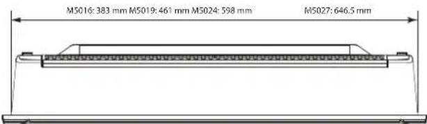
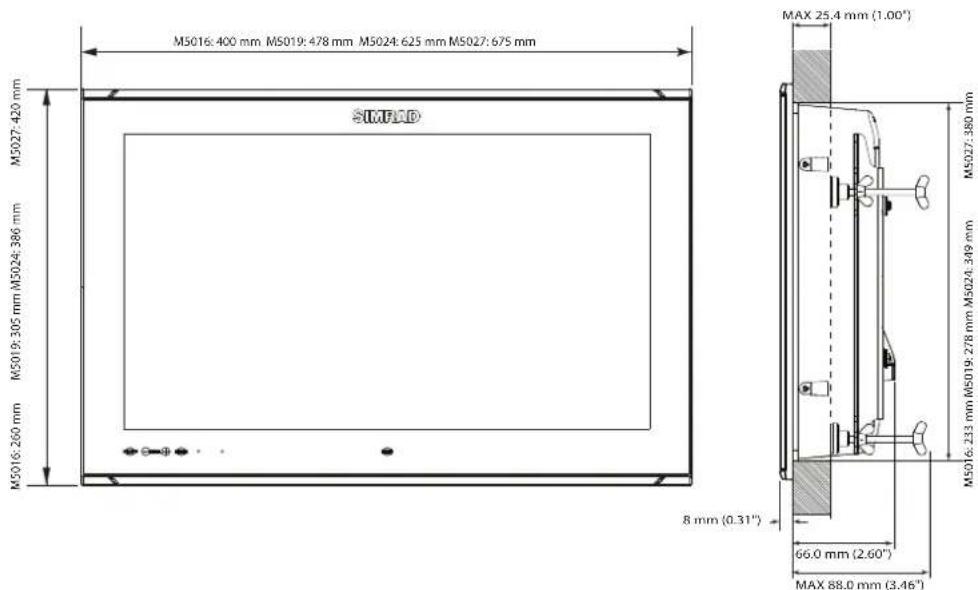
SIMRAD
- M5000 Series Monitors
- Preface
- Copyright
- Warranty
- Compliance Statements
- The Wheelmark
- Trademarks
- About this manual
- Contents
- Introduction
- Installation
- Connecting the display
- Operating the display
- Cleaning and maintenance
- Troubleshooting
- Accessories
- Specifications
- Dimensional drawings
- 1
- Introduction
- 2
- Installation
- Cutout template
- Fixing options
- Flush-mounting the display
- VESA mounting the display
- 3
- Connecting the display
- Cable retention
- Color calibration connection for MARIS ECDIS900 MK5 PC
- Serial connection using the CT&A cable
- 4
- Operating the display
- First time operation
- OSD menu
- 5
- Cleaning and maintenance
- Display removal
- Replacing the gasket
- Replacing the filters
- Other maintenance
- Updating the firmware
- Checking current firmware version
- Installing an update
- 6
- Troubleshooting
- 7
- Accessories
- 8
- Specifications
- 9
- SIMRAD
Brand : SIMRAD
Model : M5000
Category : Monitor