
SFID325B - Weight bench Body-Solid - Free user manual and instructions
Find the device manual for free SFID325B Body-Solid in PDF.


| Product Type | Weight Bench |
| Brand | Body-Solid |
| Model | SFID325B |
| Overall Dimensions | 69" L x 24" W x 38" H (174 x 61 x 97 cm) |
| Weight Capacity | 800 lbs (363 kg) |
| Product Weight | 95 lbs (43 kg) |
| Frame Material | 17-gauge heavy-duty steel |
| Back Pad Adjustment | Flat, Incline, Decline (multiple positions) |
| Seat Adjustment | Yes, adjustable angle |
| Leg Extension / Curl Attachment | Included with rotating ankle pads |
| Preacher Curl Pad | Included, adjustable |
| Foam Padding | High-density, durable foam |
| Transport Wheels | Yes, for easy relocation |
| Warranty | Lifetime frame warranty, 2-year parts |
| Assembly Required | Yes, tools included |
| Power Source | None (manual) |
| Maintenance | Periodic lubrication of moving parts; clean with mild soap and water |
| Safety Features | Locking pins for adjustments, non-slip rubber feet |
| Replaceable Parts | Foam pads, cables (if any), and adjustment knobs |
| Repair Service | Contact Body-Solid customer support for parts |
Frequently Asked Questions - SFID325B Body-Solid
User questions about SFID325B Body-Solid
0 question about this device. Answer the ones you know or ask your own.
Ask a new question about this device
Download the instructions for your Weight bench in PDF format for free! Find your manual SFID325B - Body-Solid and take your electronic device back in hand. On this page are published all the documents necessary for the use of your device. SFID325B by Body-Solid.
USER MANUAL SFID325B Body-Solid
Body-Solid® Built for Life
SFID325
natural_image
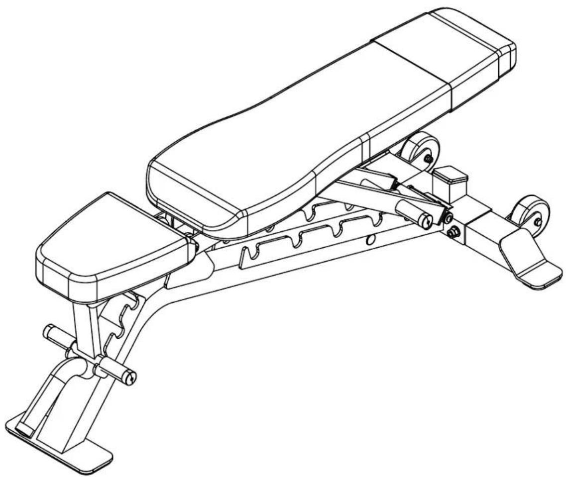
Line drawing of a balance beam exercise machine (no text or symbols)STEP 1
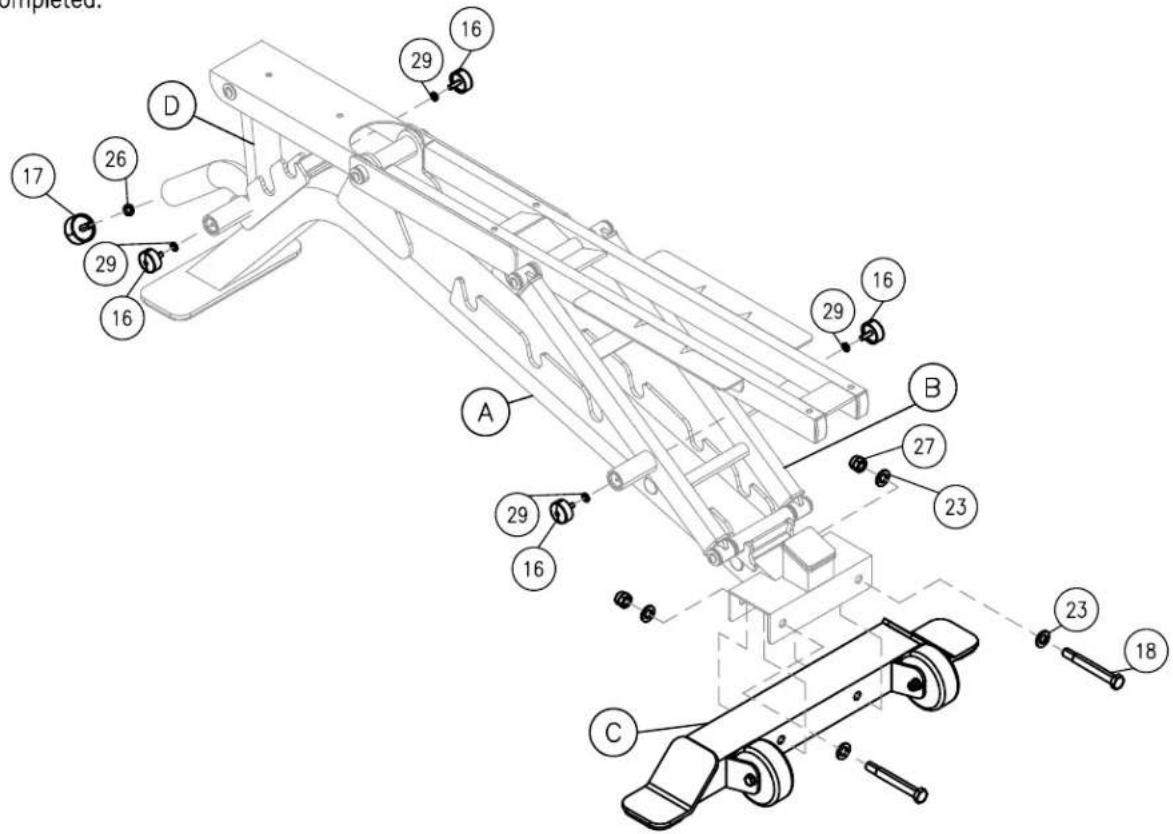
Be careful to assemble all components in the sequence they are presented.
NOTE:
Finger tighten all hardware in this step. Do Not wrench tighten until end of step 2.
A. Attach rear leg (C) to mainframe (A) as shown using:
two 18 (Hex Bolt M12 X 105mm)
four 23 (Flat Washer 12mm)
two 27 (Nylon Lock Nut M12)
B. Attach two End Cap (16) to Back Pad Support structure (B) handle as shown using:
two 16 (End Cap ∅25)
two 29 (spring washer 6mm)
C. Attach two End Cap (16) to Seat Support Structure (D) handle as shown using:
two 16 (End Cap ∅25)
two 29 (spring washer 6mm)
D. Attach two End Cap (17) to mainframe (A) front handle as shown using:
one 17 (End Cap ∅30)
one 26 (spring washer 8mm)
natural_image
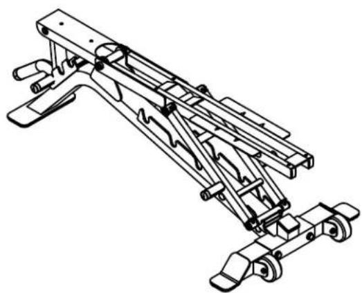
Technical line drawing of a mechanical lifting device (no text or symbols)Above shows STEP 1 assembled and completed.
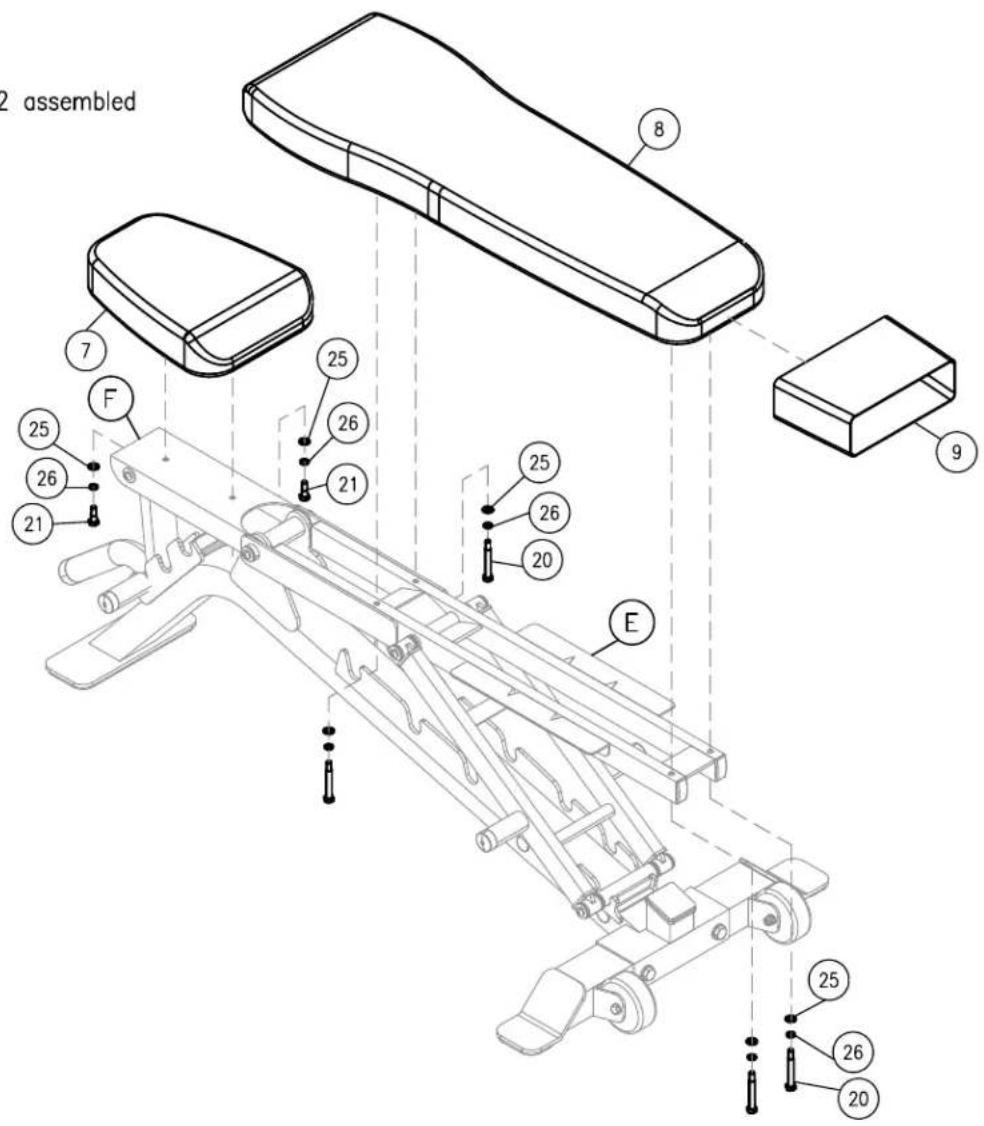
Be careful to assemble all components in the sequence they are presented.
NOTE:
Finger tighten all hardware in this step. Do Not wrench tighten until end of step 2.
A. Attach Back Pad (8) with Pad Wrap (9) to Back Pad Structure (E) as shown using:
four 20 (hex bolt M8 x 55 mm)
four 26 (spring washer 8mm)
four 25 (flat washer 8mm)
B. Attach Seat Pad (7) to Seat Pad Structure (F) as shown using:
two 21 (hex bolt M8 x 21 mm)
two 26 (spring washer 8mm)
two 25 (flat washer 8mm)
natural_image
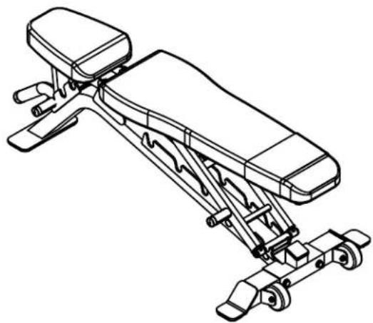
Line drawing of a horizontal bar with adjustable arms and wheels (no text or symbols)Above shows STEP 2 assembled and completed.
SFID325 Hardware
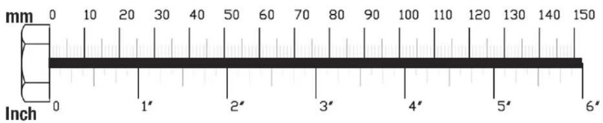
(Actual Size Shown)

(18) HEX BOLT 12mm X 105mm PARTIAL THREAD QTY. 2
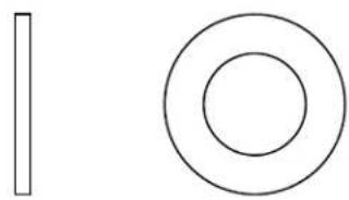
natural_image
Simple geometric shapes: a vertical rectangle and two concentric circles (no text or symbols)(23) FLAT WASHER 12mm QTY.4
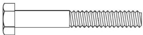
natural_image
Technical line drawing of a hexagonal bolt with threaded shaft (no text or symbols)(19) HEX BOLT M8 X 60mm PARTIAL THREAD QTY. 2
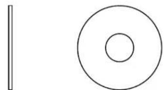
natural_image
Simple geometric shapes: a vertical line and a concentric circle (no text or symbols)(24) BIG FLAT WASHER 8mm QTY, 8
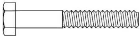
natural_image
Technical line drawing of a bolt with threaded shaft (no text or symbols)(20) HEX BOLT M8 X 55mm PARTIAL THREAD QTY. 4
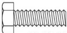
(21) HEX BOLT M8 X 25mm PARTIAL THREAD QTY. 2
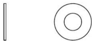
natural_image
Simple geometric shapes: a vertical line and a concentric circle (no text or symbols)(25) FLAT WASHER 8mm QTY. 10
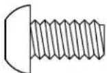
(22) ROUND ALLEN HEAD M8 X 15mm FULL THREAD BOLT QTY. 8
natural_image
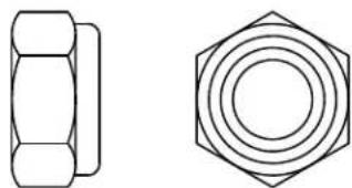
Technical line drawings of a hexagonal nut and its top view (no text or symbols)(27) NYLON LOCK NUT 12mm QTY. 2
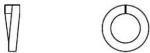
(26) SPRING WASHER 8mm QTY. 15
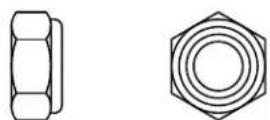
(28) NYLON LOCK NUT 8mm QTY. 2
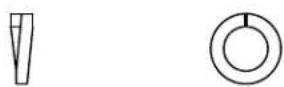
(29) SPRING WASHER 8mm QTY. 4

Mainframe Parts List
Part# Qty Description
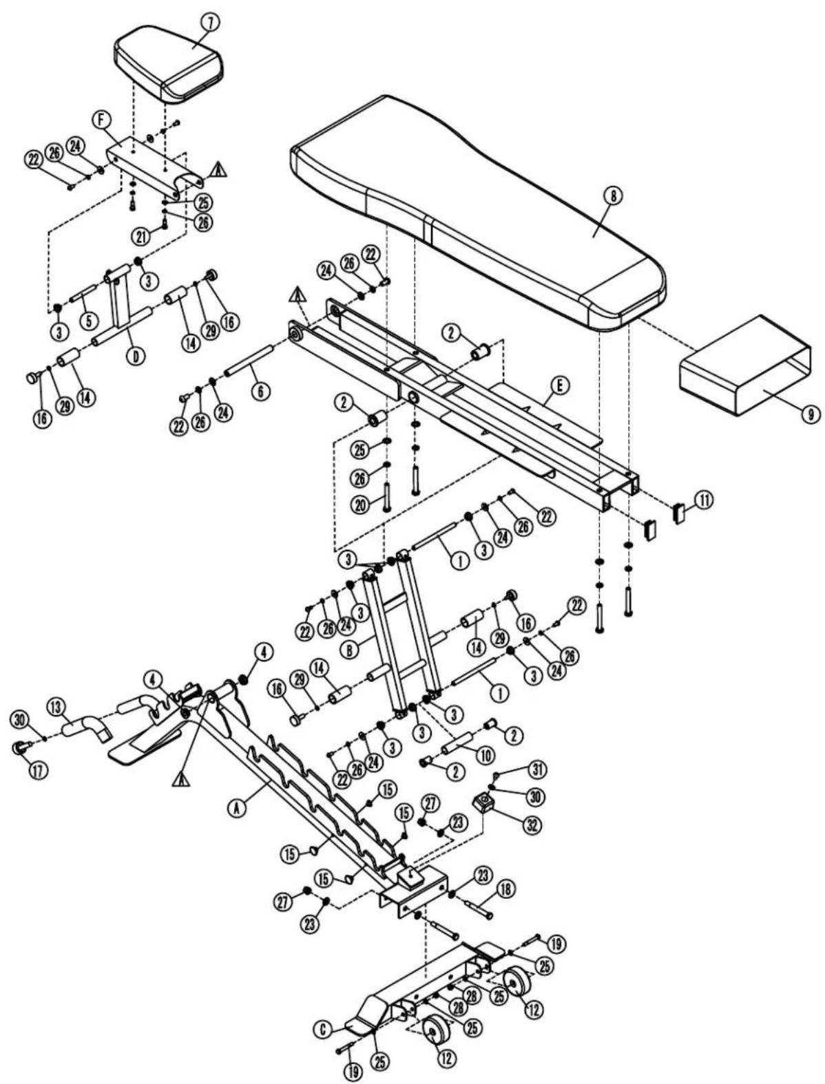
1 2 shaft
2 4 Long Bushing
3 10 Short Bushing
4 2 Bushing Φ30
5 1 Seat Pad Struture Shaft
6 1 Main Pivot Shaft
7 1 Seat Pad
8 1 Back Pad
9 1 Pad Wrap
10 1 Back Frame Support Tubing
11 2 Back Pad Structure End Cap
12 2 Transfer Wheel
13 1 Front Handle Foam Grip
14 4 Side Handle Foam Grip
15 4 Plug
16 4 End Cap Φ25
17 1 End Cap Φ30
18 2 Hex Bolt M12 X 105mm
19 2 Hex Bolt M8 X 60mm
20 4 Hex Bolt M8 X 55mm
21 2 Hex Bolt M8 X 25mm
22 8 Round Allen Head Bolt M8 X 15mm
23 4 Flat Washer 12mm
24 8 Big Flat Washer 8mm
25 10 Flat Washer 8mm
26 14 Spring Washer 8mm
27 2 Nylon Lock Nut M12
28 2 Nylon Lock Nut M8
29 4 Spring Washer 6mm
30 2 Spring Washer 10mm
31 1 Round Allen Head Bolt M10 X 20mm
32 1 Back Pad Rubber Stopper
A 1 Bottom Frame
B 1 Rear Frame
C 1 Rear Leg
D 1 Seat Pad Support Frame
E 1 Back Pad Frame
F 1 Seat Pad Board
SFID325 Exploded View
NOTE
Body-Solid® Built for Life
1900 S. Des Plaines Ave.
Forest Park, II 60130
1 (800) 556-3113
Hours: M-F 8:30 - 5:00
www.bodysolid.com
© Copyright 2010. Body-Solid. All rights reserved. Body-Solid reserves the right to change design and specifications when we feel it will improve the product. Body-Solid machines maintain several patented and patent pending features and designs. All rights reserved on all design patents and utility patents.
Brand : Body-Solid
Model : SFID325B
Category : Weight bench