AVN-PX8 - Hand blender Sonifex - Free user manual and instructions
Find the device manual for free AVN-PX8 Sonifex in PDF.


| Product Type | Hand Blender |
| Brand | Sonifex |
| Model | AVN-PX8 |
| Dimensions (L x W x H) | 7.9 x 2.8 x 4.3 inches (200 x 70 x 110 mm) |
| Weight | 1.5 lbs (0.68 kg) |
| Power Supply | AC 120V/60Hz or 230V/50Hz, 300W |
| Speed Settings | Variable speed with 2 fixed speeds |
| Blade Material | Stainless Steel |
| Shaft Material | Stainless Steel |
| Motor Type | Brushed DC Motor |
| Safety Feature | Safety lock button to prevent accidental operation |
| Dishwasher Safe Parts | Detachable shaft and blade assembly |
| Cleaning | Wipe motor body with damp cloth; blade and shaft dishwasher safe |
| Warranty | 1 year limited warranty |
| Certification | CE, RoHS compliant |
| Accessories Included | Beaker (600ml), wall mount bracket |
| Cord Length | 4.9 ft (1.5 m) |
| Noise Level | Approx. 80 dB(A) |
| Repairability | Available spare parts: blades, motor brush, power cord |
| Usage | For blending, pureeing, emulsifying in home kitchens |
Frequently Asked Questions - AVN-PX8 Sonifex
User questions about AVN-PX8 Sonifex
0 question about this device. Answer the ones you know or ask your own.
Ask a new question about this device
Download the instructions for your Hand blender in PDF format for free! Find your manual AVN-PX8 - Sonifex and take your electronic device back in hand. On this page are published all the documents necessary for the use of your device. AVN-PX8 by Sonifex.
USER MANUAL AVN-PX8 Sonifex
Presenter Mixer System


Manufacturers of audio & video products for radio & TV broadcasters
SONIFEX
Presenter Mixer System Handboc
For the latest Sonifex handbook information please vis Sonifex website at www.sonifex.co.uk
This handbook is for use with the following product: Sonifex Presenter Mixer System, consisting of the AVN-PX8x4C Mix Engine Rack, AVN-MPPR Presenter Remote Unit & AVN-MPTR Technician Remote Unit
Revision 1.03 Novembert 2021
©Sonifex Ltd, 2021
All Rights Reserved
Sonifex Ltd, 61, Station Road, Irthlingborough, Northants, NN9 5QE, England.
Tel: +44 (0)1933 650 700
Fax: +44 (0)1933 650 726
Email: sales@sonifex.co.uk
Website: https://www.sonifex.co.uk
Information in this document is subject to change without notice and does not represent a commitment on the part of the vendor. Sonifex Ltd shall not be liable for any loss or damage whatsoever arising from the use of information or any error contained in this manual.
No part of this manual may be reproduced or transmitted in any form or by any means, electronic mechanical, including photocopying, recording, information storage and retrieval systems, for any purpose other than the purchaser's personal use, without the express written permission of Sonifex Ltd. Unless otherwise noted, all names of companies, products and persons contained herein are part of a completely fictitious adaptation and are designed solely to document the use of Sonifex product.
Made in the UK by SONIFEX
Contents
Product Warranty - 2 Year Extended i
Sonifex Warranty & Liability Terms & Conditions i 1. Definitions i
- Warranty i
Unpacking Your Product ii
Repairs & Returns iii
CE Conformity iii
Safety & Installation of Mains Operated Equipment iii Voltage Setting Checks iii
Fuse Rating iii
Power Cable & Connection iii WEEE Directive iv
Atmosphere/Environment
-
Sonifex Presenter Mixer System Manual 1 Overview 1
-
AVN-PX8x4C Mix Engine Rack 2
Front Panel Controls 3
Status LEDs 3
OLED Display 3
Menu fast keys 3
Power button 3
Reset button 3
Rear Panel Connections 4
Network Ports 4
Standard GPIO Connector 4
Analogue Audio Inputs & Outputs 5
Audio Levels and dBFS equivalences 5
- AVN-MPPR Presenter Remote Unit 6
Front Panel Controls 7 Status and Mixer ID LEDs 7
Rotary Controls 8
Headphone sockets 9
@PO button 9
Reset button 10
IP address reset 10
ar Panel 10
Network Connector 10
Mix Output Mono Analogue Output 10
Standard GPIO Connector 10
Hardware ID Settings 10
Mounting the AVN-MPPR Presenter Remote Unit 10
- AVN-MPTR Technician Remote Unit 11
Front Panel Controls 11
Status LEDs 11
Mixer Selection buttons 12
GPO and Enable button 12
OLED Display 12
Menu fast keys 12
Reset button 12
Power button 12
Rear Panel 13
Network Connector 13
Standard GPIO Connector
-
Third Party API
-
Operational Specification
Startup
Authorisation
Control Precedence
Group/Studio Assignment
Configuration
- Webpages & Local Display Settings (Mix Engine)
Mix Engine web page menu structure
Information Web Page
Audio Config -> VM Sources Web Page
Audio Config -> VM Metering Web Page
Audio Config -> AoIP Output Streams Web
Audio Config -> Physical Audio Setup Web
Group Config -> Allowed Devices Web Page
Group Config ->VM Assignment Web Page
Group Config ->Group Assignments Web Page
Group Config ->Group Aliases Web Page
Misc Settings Web Page
System Web Page
Mix Engine local screen menu structure
- Webpages (Presenter Remote)
MPPR web page menu structure
Misc Settings Web Page
System Web Page
- Webpages & Local Display Settings
(Technician Remote)
MPTR web page menu structure
Misc Settings Web Page 34
System Web Page 35
MPTR local screen menu structure 36
- Technical Specifications 37
Contents
Fig 2-1: AVN-PX8x4C Front and Rear 2
Fig 3-1: AVN-MPPR Front and Rear 6
Fig 3-2A: AVN-MPPR Front Panel Illumination In Normal Operation 8
13 Fig. 3-2B: AVN-MPPR Front Panel Illumination With Knob
Pressed 9
5 Fig 3-3: AVN-MPDB Presenter Controller Desk Mount
Bracket 10
5 Fig 4-1: AVN-MPTR Front and Rear 11
6 Fig 7-1: Information Web Page 19
Fig. 7-3: Source Dialog 20
Fig. 7-4: Physical Input Dialog 20
19 Fig 7-5: AoIP Input Dialog 20
Fig207-2: Audio Config -> VM Sources Web Page
Fig217-6: Audio Config -> VM Metering Web Page
PageFig227-7: Audio Config -> AoIP Output Streams Web Pac
Page 23 Fig. 17-8: Audio Config -> Physical Audio Setup Web Pac
Fim 7-9: Group Config -> Allowed Devices Web Page
126 7-9. Group Coming → Allowed Devices Web Page
Fig 7-10: Group Config -> Editing a device
Fig 7-11: Group Config -> Adding a device
28 Fig 7-12: Group Config ->VM Assignment Web Page
29 Fig 7-14: Confirmation Dialog 27
32 Fig 7-13: Group Config ->Group Assignments Web Page
Fig 7-15: Group Config ->Group Aliases Web Page
32 Fig 7-16: Misc Settings Web Page 28
33 Fig 7-17: System Web Page 29
4 Fig 7-18: Misc Settings Web Page 32
34g 7-19: Misc Settings Web Page 34
Warranty Registration
SONIFEX
Register Online for an Extended 2 Year Warranty
As standard, Sonifex products are supplied with a 1 year back to warranty.
If you register the product online, can increase your product warranty 2 years and we can also keep you informed of any product design improvements or modifications.
ase Product:
you Serial No: to
To register your product, please go online to www.sonifex.co.uk/register
Warranty
Product Warranty - 2 Year Extended 'the Contract' means the quotation, these Conditions of Sale and any other document incorporated in a contract between the Company and the Purchaser. As standard, Sonifex products are supplied with a 1 year back to base warranty. In order to register the date of purchase and so that we can keep
you informed of any product design improvements or modifications, if this is the entire Contract between the parties relating to the subject important to complete the warranty registration online. Additionally, if matter hereof and may not be changed or terminated except in writing it register the product on the Sonifex website, you can increase your productance with the provisions of this Contract. A reference to the conse warranty to 2 years. Go to the Sonifex website at: www.sonifex.co.uk/acknowledgement, authority or agreement of the Company means in register to apply for your 2 year warranty. writing and only by a director of the Company.
Note: For your own records the product serial number is recorded on the 2. Warranty
CE certification page of this handbook.
Sonifex Warranty & Liability Terms & Conditions
1. Definitions
'the Company' means Sonifex Ltd and where relevant includes companies within the same group of companies as Sonifex Limited.
'the Goods' means the goods or any part thereof supplied by the Company and where relevant includes: work carried out by the Company on items supplied by the Purchaser; services supplied by the Company; and software supplied by the Company.
'the Purchaser' means the person or organisation who buys or has agreed to buy the Goods.
a. The Company agrees to repair or (at its discretion) replace Goods which are found to be defective (fair wear and tear excepted) and which are returned to the Company within the Warranty Term provided that each of the following are satisfied:
i. notification of any defect is given to the Company immediately upon its becoming apparent to the Purchaser;
the Goods have only been operated under normal operating conditions and have only been subject to normal use (and in particular the Goods must have been correctly connected and must not have been subject to high voltage or to ionising radiation and must not have been used contrary to the Company's technical recommendations);
'the Price' means the Price of the Goods and any other charges incurred by the Goods are returned to the Company's premises at the the Company in the supply of the Goods. Purchaser's expense;
'the Warranty Term' is the length of the product warranty which is usually any Goods or parts of Goods replaced shall become the 12 months from the date of despatch; except when the product has been property of the Company;
registered at the Sonifex website when the Warranty Term is 24 months from the date of despatch.
v. no work whatsoever (other than normal and proper maintenance) has been carried out to the Goods or any part of the Goods without the Company's prior written consent;
Warranty
vi. the defect has not arisen from a design made, furnished ore. specified by the Purchaser;
vii. the Goods have been assembled or incorporated into other goods only in accordance with any instructions issued by the Company;
viii. the defect has not arisen from a design modified by the Purchaser;
ix. the defect has not arisen from an item manufactured by a person other than the Company. In respect of any item manufactured by a person other than the Company, the Purchaser shall only be entitled to the benefit of any warranty guarantee provided by such manufacturer to the Company.
b. In respect of computer software supplied by the Company the Company does not warrant that the use of the software will be uninterrupted or error free.
c. The Company accepts liability:
i. for death or personal injury to the extent that it results from the negligence of the Company, its employees (whilst in the course of their employment) or its agents (in the course of the agency
ii. for any breach by the Company of any statutory undertaking as to title, quiet possession and freedom from encumbrance.
d. Subject to conditions (a) and (c) from the time of despatch of the Goods from the Company's premises the Purchaser shall be responsible for any defect in the Goods or loss, damage, nuisance
interference whatsoever consequential economic or otherwise or wastage of material resulting from or caused by or to the Go
particular the Company shall not be liable for any loss of profits. Each product is shipped in protective packaging and should be inspected for other economic losses. The Company accordingly excludes all liability for the same. The company's product packaging and notify the carrier immediately with all the relevant
At the request and expense of the Purchaser the Company will test the Goods to ascertain performance levels and provide a report of the results of that test. The report will be accurate at the time of the test, to the best of the belief and knowledge of the Company, and the Company accepts no liability in respect of its accuracy beyond that set out in Condition (a).
f. Subject to Condition (e) no representation, condition, warranty or other term, express or implied (by statute or otherwise) is given by the Company that the Goods are of any particular quality or standard or will enable the Purchaser to attain any particular performance or result, or will be suitable for any particular purpose or use under warranty specific conditions or will provide any particular capacity, notwithstanding that the requirement for such performance, result or capacity or that such particular purpose or conditions may have been known (or ought to have been known) to the Company, its employees or agents.
g. (i) To the extent that the Company is held legally liable to the Purchaser for any single breach of contract, tort, representation from the course or other act or default, the Company's liability for the same shall not exceed the price of the Goods.
The restriction of liability in Condition (g)(i) shall not apply to any liability accepted by the Seller in Condition (c).
h. Where the Goods are sold under a consumer transaction (as defined by the Consumer Transactions (Restrictions on Statements) Order 1976) the statutory rights of the Purchaser are not affected by these or Conditions of Sale.
ds In Unpacking Your Product
details of the shipment. Packing materials should be kept for inspection and also for if the product needs to be returned.
The product is shipped with the following equipment so please check ensure that you have all of the items below. If anything is missing, contact the supplier of your equipment immediately.
Item Quantity
Product unit 1
IEC mains lead fitted with moulded mains plug 1
If you require a different power lead, please let us know when ord product.
Repairs & Returns
Please contact Sonifex or your supplier if you have any problems with Sonifex product. Email technical.support@sonifex.co.uk for the repair/upgrade/returns procedure, or for support & questions regarding the product operation.
CE Conformity
The products in this manual comply with the essential requirements relevant European health, safety and environmental protection legislati
The technical justification file for this product is available at Sonifex Ltd.
The declaration of conformity can be found at: http://www.sonifex.co.uk/declarations
i on and Safety & Installation of Mains Operated Equipment
There are no user serviceable parts inside the equipment. If you should ever need to look inside the unit, always disconnect the mains supply before removing the equipment covers. The cover is connected to earth by means of the fixing screws. It is essential to maintain this earth/ground connection to ensure a safe operating environment and provide electromagnetic shielding.
Voltage Setting Checks
Entire that the machine operating voltage is correct for your mains power supply by checking the box in which your product was supplied. The volt is shown on the box label. The available voltage settings are 115V, or 2: Please note that all products are either switchable between 115V and 230
Fuse Rating
The product is supplied with a single fuse in the live conducting path of mains power input. For reasons of safety it is important that the correct rating and type of fuse is used. Incorrectly rated fuses could present a possible fire hazard, under equipment fault conditions. The active fuse is fitted on the outside rear panel of the unit.
Power Cable & Connection
An IEC power connector is supplied with the product which has a mould plug attached.
The mains plug or IEC power connector is used as the disconnect device. The mains plug and IEC power connector shall remain readily operable to disconnect the apparatus in case of a fault or emergency.
The mains lead is automatically configured for the country that the produce is being sent to, from one of:
Safety & Installation
Territory Voltage IEC Lead Type Image
| UK & Middle East 230V UK 3 pin to IEC lead |  | ||
| Europe 230V | European Schuko round 2 pin IEC lead |  | |
| USA, Canada and South America | 115V 3 flat pin to IEC lead |  | |
| Australia & New Zealand | 230V Australasian 3 flat pin to IEC le |  | |
Connect the equipment in accordance with the connection details and before applying power to the unit, check that the machine has the operating voltage for your mains power supply.
This apparatus is of a class I construction. It must be connected to socket outlet with a protective earthing connection.
Important note: If there is an earth/ground terminal on the rear part, the product then it must be connected to Earth.
WEEE Directive

The Waste Electrical and Electronic Equipment (WEEE) Directive was agreed on 13 February 2003, along with the related Directive 2002/95/EC on Restrictions of the use of certain Hazardous Substances in electrical and electronic
equipment (RoHS). The Waste Electrical and Electronic Equipment Directive (WEEE) aims to minimise the impacts of electrical and electronic equipment on the environment during their life times and when they become waste. All products manufactured by Sonifex Ltd have the WEEE directive label
placed on the case. Sonifex Ltd will be happy to give you information about correct local organisations that can reprocess the product when it reaches its "end of use", or alternatively all products that have reached "end of use" can be returned to Sonifex and will be reprocessed correctly free of charge.
Atmosphere/Environment
This apparatus should be installed in an area that is not subject to excessive temperature variation ( <0^, >50^ ), moisture, dust or vibration.
This apparatus shall not be exposed to dripping or splashing, and no objects filled with water, such as vases shall be placed on the apparatus.
1. Sonifex Presenter Mixer System Manual
Overview
The presenter mixer system allows on-air presenters to adjust the audio levels fed to their radio or wired IEM systems, whilst also allowing Sound Control Room operators to adjust the levels remotely. The system consists of 3 types of unit all connected on a common Ravenna Audio over IP (AoIP) network with added audio sources derived from Ravenna based AoIP mixers or input portals. Setup and control can be provided via webpages and/or 3 applications. The system uses mono audio throughout.
The 3 units are:
• AVN-PX8x4C - a 2U rack mounted Mix Engine Rack.
• AVN-MPPR - a small desk, or microphone stand, mounted Presenters' Remote Unit – aka PRU.
- AVN-MPTR - a 1U rack mounted Technicians' Remote Unit - aka TRU.
2 AVN-PX8x4C Mix Engine Rack
2. AVN-PX8x4C Mix Engine Rack
Power Button used to indicate power status, switch action can be disabled in software

AVN-PX8x4C 8x4 mixer with 24 audio inputs & 16 audio outputputs & outputs provided on D-Types in AES59 format

Fig 2-1: AVN-PX8x4C Front and Rear
Power supplies with knurled thumb screws for easy removal
The Mix Engine, as well as using AES67 audio streams, accepts 24 an optional that both MPTRs could also select the same VM so a maximum of 6 mono input channels on 3 x DB25 connectors and output 16 analog devices can control the mix levels of a VM.
channels on 2 x DB25 connectors. Each mixer unit is able to create and control 8 virtual mixers, each capable of mixing any 4 sources (analogue or AoIP) to a single mixed output that is available locally at an output and via an AoIP stream (to the Presenter Unit and other destinations). The analogue audio line-up level will default to +18dBU = 0dBFS. The Mix Engine will allow a maximum of 32 audio over IP input streams (each stream can be up to 8 channels). There are 8 virtual mixer outputs available. Each Virtual Mixer has 4 sources and 1 mixed output. There are also 2 more monitor outputs which play out the audio of the VM selection made on each of the 2 connected Technician Remote Units.
A built-in webserver is used for configuration settings, input/output and for defining which Presenter and Technician Remote Units are to the particular Mix Engine and Virtual Mixers. Up to 4 MPPRs can be assigned to each Virtual Mixer on a first-come first-served basis. It's
The Mix Engine has dual universal AC power supplies which are hot-swappable assigned in the event of failure and have a green LED to indicate within spec operation. The front panel has LED indications and GPOs to warn of power supply failure. There are also front panel LEDs for network and sync/clock failure.
Front Panel Controls
Status LEDs
On the left side of the panel, there are a number of status LEDs used to provide a basic overview of various system parameters such as power supply failure, network and sync/clock failures.
Each of these LEDs can be illuminated in different combinations of and flashing or non-flashing states. The table below provides an over what each LED state signifies.
| Led Name | State Description | |
| AoIP Red | No network | connection on AoIP network port |
| Green AoIP | network port connected. | |
| Ethernet Red | Red No network connection on control network port | |
| Green Control network port connected. | ||
| Auth Off | Auth LED not currently used. | |
| Clock Red | PTP master | offset clock is greater than 10000ns. |
| Yellow PTP | master offset is less than 10000ns but greater than 1000ns. | |
| Green PTP | master offset is less than 1000ns. Or this unit is the master clock. | |
| Flash Yellow | PTP in listening state - master clock negoti taking place. | |
| PSU1/PSU2 | Red Power | state error |
| Yellow Power | state warning | |
| Green Power | state is OK | |
OLED Display
The OLED display allows the user to view system info such as the IP address, serial number etc. It also allows the user to name the unit, check or change which are the network settings, set brightness of the LEDs or contrast of the OLED, as and to change the mixer sources used for the selected Virtual Mixer. These menus are selected by pressing the menu fast key (see below) or holding colowns the centre button on the selector spinwheel for around half a second view they can be set to require a password before access is granted.
Menu fast keys
The are 4 menu fast keys are available to help jump to the corresponding menu on the OLED display.
- "Menu" jumps to the Main menu.
- "Assign" jumps to the VM assign menu where the user can assign a VM to a particular group of MPPRs.
- "Release" jumps to the release menu which allows the user to release a particular group of MPPRs.
- "Grab" jumps to the grab menu which allows user to grab a particular group of MPPRs.
ation Power button
The Front Panel on/off button is configured to power up the unit from Standby mode and can be enabled to provide a power off function. The function will always default to power off disabled - the user would need to enter the system menu to enable this function. When the power off function is enabled, pressing and holding the power button for 2 seconds will power down the unit.
Reset button
The recessed reset button at the bottom left corner of the front panel triggers a hardware reset of the unit.
2 AVN-PX8x4C Mix Engine Rack
Rear Panel Connections
Network Ports
The Mix Engine has 2 network ports; the primary port is the AoIP p is mainly used for the transport of audio - between the Mix Engine MPPRs, and between the Mix Engine and the Main Studio Mixing De network will also provide connection for discovery of devices and Em control, status and metering information.
The control port will provide webserver access to settings. This port intended to run on a physically different network, so engineers/operat can interrogate/set device parameters on the system without their net overhead impacting on the AoIP network. The webserver can also be accessed via the AoIP port.
Standard GPIO Connector
This is a 15-way female 'D'-type connector which has 10 ports with pin assignable direction & function, and a voltage free relay switched output with normally open and normally closed contacts. The Technician and Presenter Units have a single connector, and the Mix Engine has two of
these connectors, allowing 20 x GPIO and 2 x relay closures.
| Pin Number Description | |
| Pin 1 GPIO 1 | |
| Pin 2 GPIO 2 | |
| Pin 3 the GPIO 3 | |
| Pin This GPIO 4 | |
| Pin 5 GPIO 5 | |
| Pin 6 Relay - Normally open contact | |
| Pin 7 Relay - Normally closed contact | |
| Pin 8 Relay - common | |
| Pin 9 GPIO 6 | |
| Pin 10 GPIO 7 | |
| Pin 11 GPIO 8 | |
| Pin 12 GPIO 9 | |
| Pin 13 GPIO 10 | |
| Pin 14 Fused (200mA) +12V DC supply | |
| Pin 15 Ground | |
When the pin is defined as an input then the pin should be pulled to ground to activate it. When the pin is defined as an output then when the output is active the pin will be pulled to ground – and is capable of sinking 20mA.
Analogue Audio Inputs & Outputs
The audio inputs and outputs on the mix engine are all on 25-way female 'D'-type connectors. (Note the same connector type for both inputs and outputs) so that standard Tascam analogue (AES59) cables can be used.
| Pin Number | Analogue Input Description | Analogue Output Description | Pin Number | Analogue Input Description | Analogue Output Description |
| Pin 1 In 8 + | (Phase) Out 8 + (Phase) | Pin 14 In 8 - (Non Phase) | Out 8 - (Non Phase) | Phase) | |
| Pin 2 In 8 GND | Out 8 GND | Pin 15 In 7 + (Phase) | Out 7 + (Phase) | Phase) | |
| Pin 3 In 7 - | (Non Phase) Out 7 - (Non Phase) | Pin 16 | In 7 GND Out | 7 GND | |
| Pin 4 In 6 + | (Phase) Out 6 + (Phase) | Pin 17 In 6 - (Non Phase) | Out 6 - (Non Phase) | Phase) | |
| Pin 5 In 6 GND | Out 6 GND | Pin 18 In 5 + (Phase) | Out 5 + (Phase) | Phase) | |
| Pin 6 In 5 - | (Non Phase) Out 5 - (Non Phase) | Pin 19 | In 5 GND Out | 5 GND | |
| Pin 7 In 4 + | (Phase) Out 4 + (Phase) | Pin 20 In 4 - (Non Phase) | Out 4 - (Non Phase) | Phase) | |
| Pin 8 In 4 GND | Out 4 GND | Pin 21 In 3 + (Phase) | Out 3 + (Phase) | Phase) | |
| Pin 9 In 3 - | (Non Phase) Out 3 - (Non Phase) | Pin 22 | In 3 GND Out | 3 GND | |
| Pin 10 | In 2 + (Phase) Out 2 + | (Phase) Pin 23 In 2 - (Non Phase) | Phase) Out 2 | - (Non Phase) | |
| Pin 11 | In 2 GND Out 2 GND | Pin 24 In 1 + (Phase) | In 1 + (Phase) | Out 1 + (Phase) | |
| Pin 12 | In 1 - (Non Phase) | Out 1 - (Non Phase) | Pin 25 | In 1 GND | Out 1 GND |
| Pin 13 | N/C | N/C | |||
Audio Levels and dBFS equivalences
Each of the analogue inputs and outputs can be configured to set the desired 0dBFS line-up level. By default, this setting is 0dBFS = +18dBu, for operation in most European countries, however this can be modified to one of the following values: +12dBu, +15dBu, +18dBu, +20dBu, +22dBu or +24dBu, to match global requirements. This setting is changed via the web browser, by clicking Configuration >Audio Config >Physical Audio Setup (see section 7 Audio Config -> Physical Audio Setup Web Page)
3 AVN-MPPR Presenter Remote Unit
3. AVN-MPPR Presenter Remote Unit
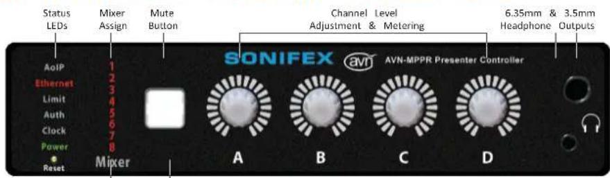
Mixer being controlled indicator Mute button can be LEDs. Green = connected mixer, labelled as required: Red = mixer waiting for Mute, Cough, etc. "approval". These LEDs are hidden until lit, to prevent confusion with meter LEDs.
Main PoE plus network audio & data connection
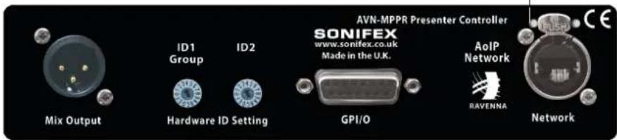
Fig 3-1: AVN-MPPR Front and Rear
The MPPR Presenter Remote Unit - also known as the PRU, will provide control levels to the virtual mixer, and display the status information and data generated by the mixer. The virtual mixer audio output will be available on the rear panel Mix Output or via headphone outputs on the front panel.
Front Panel Controls
Status and Mixer ID LEDs
On the left side of the panel, there are a number of status LEDs at the word "Mixer" there is also an indication of the virtual mixer being controlled. When the unit has been grabbed by a mix engine and to a virtual mixer, the appropriate LED will be illuminated to indicate virtual mixer currently under control. If the unit is not currently assigned a virtual mixer, the Mixer ID LEDs will all flash red to indicate that case.
There are also a number of status LEDs which are used to provide overview of various system parameters. A software enabled limiter on Virtual Mixer output is configured to prevent audio over-hitting. When limiter is operational, the front panel Limit LED illuminates red. The panel also has LED indication to warn of power supply failure, network sync/clock failures.
Each of these LEDs can be illuminated in different combinations of c and flashing or non-flashing states. The table on the next page provides what each LED state signifies.
| Led Name | State Description | |
| nd aboveing assigned the signed to | Off Unit has not joined an audio multicast group. | |
| Red | Unit has joined an audio multicast group but audio data is being received | |
| Green | Unit has joined an audio multicast group and audio data is being received. | |
| this is the Ethernet | Red No network connection | |
| Green Network connected | ||
| a basic limit the front | Off | Audio level for the virtual mixer that is und control is OK |
| Red | Audio level for the virtual mixer that is und control is limiting. | |
| work and Auth | Flash Yellow | Unit has not yet been grabbed by a mix er |
| Green Unit | has been grabbed by a mix engine | |
| pours des and Clock | Red PTP master offset clock is greater than 10000ns. | |
| Yellow | PTP master offset is less than 10000ns but greater than 1000ns. | |
| Green | PTP master offset is less than 1000ns. Or th is the master clock. | |
| Flash Yellow | PTP in listening state - master clock negotia taking place. | |
| Power | Red Power state error | |
| Yellow Power state warning | ||
| Green Power state is OK | ||
3 AVN-MPPR Presenter Remote Unit
Rotary Controls
The rotary encoders on the front panel act as level controls for the sources assigned to the virtual mixer that the unit is currently controlled. Turning the encoder will increase/decrease the mix level by 4dB per 100 MHz from Mute, then -80dB up to -60dB, switching to 2dB per step up between -60dB and a maximum of +10dB gain. The total number of 41 which represents just under 2 complete rotations and will be shown in the level display by the 21 LEDs. This level is shown on the scale I LED pattern, so that initially LED 1 will be lit then LEDs 1 & 2, then only then LEDs 2&3 etc, so we have a total of 42 states between maximum.
Level Mode
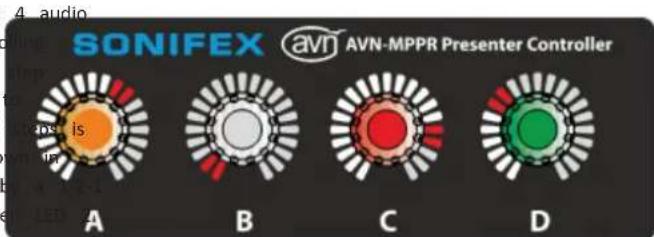
mute and Fig 3-2A: AVN-MPPR Front Panel Illumination In Normal Operation
It is possible for a technician unit to lock out presenter units from The default display mode is "Level". In this mode, the level of each channel controlling the signal levels for a virtual mixer. In this case, the rotary shown by the LEDs around the rotary controls. The rotary controls are controls will be illuminated blue with the level or metering displayed illuminated to show the signal presence of the assigned audio channel and LEDs around the control (depending on the display mode that is set will see off when no audio is present. The controls will be illuminated green, below). If the user of the unit attempts to adjust a level by turning yellow or red when the audio input level is within certain thresholds; green encoder, the encoders will all flash blue to indicate that the user input yellow/normal, yellow high and red the overload state.
received but no level change will actually take place – the technician unit
will have to reinstate control to the presenter unit to allow it to pressing the control will activate the metering display around the rotary levels again. control, with a system wide scale showing signal level in green, yellow and red sections. The metering will be displayed until a configurable timeout
There are 2 selectable display modes that allow the user to select what expired or until the control is pressed or turned again. The timeout is displayed by the LEDs around the rotary encoders. The "Display Mode configurable in the "Misc Settings" section of the web page using the be set from the "Misc Settings" section in the web pages for the undefined Display Duration" setting. The default duration is 20 seconds. web page menu, the modes are called "Level" and "Metering".
Metering Mode
Press knob to show metering.
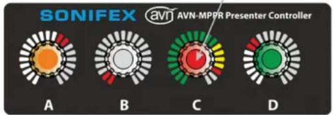
Fig 3-2B: AVN-MPPR Front Panel Illumination With Knob Pressed
The second display mode is "Metering". In this mode, the metering each channel is shown by the LEDs around the rotary controls. The controls are not normally illuminated in this mode.
Pressing or turning the control will activate the displaying of the level for the channel. The level is displayed until the configured Display Duration" timeout expired or until the control is pressed
Virtual Mixer Assignment
It is possible to reassign the virtual mixer (VM) for the MPPR via panel rotary controls. This is only possible if the unit is grabbed by engine – this is indicated by the Auth led being illuminated green.
VM assignment mode, press and hold rotary controls A and B simultaneously for 3 seconds. Once the unit enters VM selection m rotary control D will be illuminated blue. Turning rotary control D through the VMs as indicated by the Mixer LEDs. Once the Mixer corresponds to the desired VM selection is illuminated, press rotary D to confirm the new selection.
Headphone sockets
XLR Mute
By default, the audio on the XLR output on the rear of the unit is not when headphones are connected to one of the sockets on the front of unit. However, there is a "Headphone XLR Mute" configuration setting in the "Misc Settings" section of the webpages to enable the muting of the XLR output on headphone connection if required.
Attenuation
The headphones will have an additional software-configurable output level control (one for each headphone output) to set the attenuation of the signal to the headphone driver for comfortable levels at normal signal level data of from the output. At present we know of 3 headphone types - 120 Ohm rotary (default), 2 kOhm (high impedance), and 8 Ohm (low impedance). The maximum output of the headphone drivers is +12dBu so the minimum
curatenuation parameter is 6db, which is present for all headphone types. The "Alteratuation parameter will act as a second attenuation and will have a againrange from 0 to 24dB – the latter value will be chosen to provide suffi range to easily cater for the lowest impedance headphones. The "6.35mm Att." and "3.5mm Att." attenuation settings can be set via the web page at the front of the Misc Settings" section.
ToPentebutton
The button between the Mixer LEDs and the rotary controls provides a virtual GPO from the unit that can be used on the Mix Engine to trigger its remote port. This button will illuminate red when it has been LEDed by this MPPR and will be yellow when initiated by a paralleled control or MPTR. A MPPR can only de-assert a GPO that it has originally assessed. However, the GPO can always be de-asserted by a MPTR. The selection of the GPO is determined by the VM that the MPPR is current connected - VM1 maps to GPO1 and so on to VM8, which maps to GP. The text on the button is a plastic insert so can be changed to suit your particular application.
3 AVN-MPPR Presenter Remote Unit
Reset button
The recessed reset button at the bottom left corner of the front triggers a hardware reset of the unit
IP address reset
As well as being able to set the IP address of the unit via the wall also possible to reset the IP address of the unit from the front panel factory default. To carry out the reset, press and hold the GPO but rotary control D while the unit is booting up. This will take roughly 2 seconds. When the IP address is reset, the Ethernet LED will be ill used. Yellow and all 4 encoders and the GPO button will flash yellow for 2 seconds. The unit will then reboot. The IP address of the unit will be reset to the factory default of 192.168.0.100.
Rear Panel
The rear panel of the Presenter Unit has three connectors and two
Network Connector
This is a Neutrik etherCON RJ45 CAT5e connector with latching lock PoE plus for unit power
Mix Output Mono Analogue Output
The mix output is a XLR 3 pin XLR male output which is electronically balanced, which has the following connections:
| Pin Number Description | |
| Pin 1 Screen | |
| Pin 2 Phase | |
| Pin 3 Non-phase | |
Standard GPIO Connector
This is a 15-way female 'D'-type connector with the same pin connects as for the AVN-PX8x4C Mix Engine.
Hardware ID Settings
These are two 16 position rotary switches, currently labelled ID1 Group and ID2. ID1 (Group) rotary switch selects the group assignment for the MPPR and is used by the Mix Engine when determining which MPPRs to grab and authorise. Currently ID 2 is unused, but it may be necessary to use this ab pages, it is selection to extend the ID1 allocation if the number of group selections nel to a exceeds 16.
Mounting the AVN-MPPR Presenter Remote Unit
There are two mounting methods: around 5
then AEN-MPDB Presenter controller desk mount bracket allows the Unit to be mounted either up on the underside or top side of a desk.
The AVN-MPMB Presenter controller desk mount, controls is a bracket that mounts to the underside of the Unit and allows it to be fixed to the top of a 5 Whitworth microphone stand screw socket. It has with adjustments in various planes to allow it to be suitably positioned in front of, or to the side of. Preser.
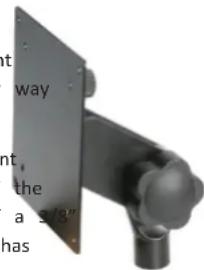
Fig 3-3: AVN-MPDB Presenter Controller Desk Mount Bracket
4. AVN-MPTR Technician Remote Unit

Mute button is normally a display of Mute activity on the selected mixer. Pressing the Enable button allows the Mute button to become active as a control. This can be software configurable/allowable.
Select which mixer the technician unit 4 x Channel volume controls. 21 LEDs normally show volume setting controls. These buttons can be coloured to show other states. of the knob. Press knob to show: Input level meter. Knob illuminates green to show audio present and red when limiting.
Main PoE Network Audio & Data Connection

Fig 4-1: AVN-MPTR Front and Rear
Each of these LEDs can be illuminated in different combinations of colour
The MPTR Technician Remote Unit - also known as the TRU - allows a technician to have control of a Virtual Mixer, paralleling the Presenter and hashing of non-flashing states. The table below provides an overview what each of the LED states signifies.
Remote Unit controls. The MPTRs are assigned to a gallery and hence normally tied to a Mix Engine. Note that no audio is present on the Technician's Remote Unit – the monitor audio for this is provided by output on the Mix Engine routed to the technician's area, but this has similar connectivity to the MPPR and we can supply audio enable versions of the MPTR if required.
Front Panel Controls
Status LEDs
On the left side of the panel, there are a number of status LEDs used to provide a basic overview of various system parameters. A s enabled limiter on the Virtual Mixer output is configured to prevent over-hitting. When the limiter is operational, the front panel Limit Li illuminates red. The front panel also has LED indication to warn of supply failure, network and sync/clock failures.
| e areLed Name State | Description | |
| AolP Off AoIPan | LED not currently used. | |
| productEtherneted | Red No network connection | |
| Green Network | connected | |
| Limit | Off | Audio level for the virtual mixer th under control is OK |
| Red | Audio level for the virtual mixer th under control is limiting. | |
| which areSoftware | Flash Yellow | Unit has not yet been grabbed by engine. |
| Green Unit has | been grabbed by a mix engine | |
| audioOff Clock | LED not currently used. | |
| Dpower | Red Power state error | |
| Yellow Power state warning | ||
| Green Power state is OK | ||
4 AVN-MPTR Technician Remote Unit
Mixer Selection buttons
OLED Display
The Virtual Mixer (VM) to be controlled is selectable using the VirtualMiOLED display allows the technician to view system info such as the IP buttons labelled Pres 1 – Pres 8 on the front panel. (Note that keypad press, serial number etc. It also allows the user to name the unit, check buttons are used so labels can be produced for different virtual mixer or change the network settings, set brightness of the LEDs or contrast of names). The mixer selection buttons are only active when the MPTR the OLED, and to change the mixer sources used for the selected Virtual grabbed by a mix engine (as indicated by a green Auth LED). When MixerM These technician menus are selected by pressing the menu fast key selected, the corresponding button will be illuminated green (or blue (see below) or holding down the centre button on the selector spinwheel MPPR lock out is set for that VM – see below). If no VM is selected, there shall half a second, and they can be set to require a password before the mixer select button LEDs will be off. Once a VM has been selected, this granted.
rotary encoders act in the same way as on the Presenter Unit. (See section
3, Rotary Controls – note that the VM assignment mode detailed in section fast keys
3, Metering Mode, is not present on the MPTR) The are 4 menu fast keys are available to help jump to the corresponding menu on the OLED display.
The MPTR is able stop MPPRs that are assigned to a particular VM from controlling the source levels (see section 3, Rotary Controls, for details "Menu" jumps to the Main menu.
the MPPR lock out behaviour). To initiate the MPPR lockout, press and "Assign" jumps to the VM assignment menu which allows the MPTR to the corresponding mixer select button for 2 seconds. The Mixer select assign a VM to a particular group of MPPRs
button will be illuminated blue to indicate that the MPPR lock out is "release" jumps to the release menu which allows the MPTR to tell the VM. To clear the MPPR lockout and allow MPPRs to control the levels engine to release a particular group of MPPRs.
again, press and hold the mixer select button for 2 seconds. The LED "grab" jumps to the grab menu which allows the MPTR to tell the mix turn green to indicate normal operation. engine to grab a particular group of MPPRs.
Reset button
GPO and Enable button
In normal operation, the GPO (or user selected text) button shows only triggers a hardware reset of the unit.
whether the GPO has been activated by a Presenter Unit and pushing it
does nothing. When the Enable button is selected (which is shown who power button
the Enable button is illuminated green), the GPO button then acts in The Front Panel on/off button is configured to power up the unit from same way as on the Presenter Unit, i.e. the Enable button acts as standard mode and can be enabled to provide a power off function. The enabling the operation of the GPO button. The GPO button will illumination will always default to power off disabled - the user would need to red when it has been selected by this MPTR and will be yellow whenter the system menu to enable this function. When the power off initiated by a paralleled MPPR or MPTR. A MPTR can de-assert any function is enabled, pressing and holding the power button for 2 seconds regardless of the original device that asserted it. will power down the unit.
AVN-MPTR Technician Remote Unit 4
Rear Panel
The rear panel of the Technicians Unit has two connectors:
Network Connector
This is a Neutrik etherCON RJ45 CAT5e connector with latching lock with PoE plus for unit power.
Standard GPIO Connector
This is a 15-way female 'D'-type connector with the same pin connection details as for the AVN-PX8x4C Mix Engine Rack.
5 Third Party API
5. Third Party API
We are using a protocol called Ember+ for the IP control so all control and status messages are available to third parties using Ember+.
There is a simple app (EmberPlusViewer) for a Windows PC that can be invoked to show this functionality and Ember+ is a freely usable protocol. We will publish relevant schemas as we develop them, with full specifications of the parameters used.
We also have available a simple PC application that will use Bonjour (mDNS-SD) to show devices available on the network and to provide basic device info about them.
6. Operational Specification
Startup
that it controls. This association will be driven by either the Hardware ID
All units will have a unique ID since each unit will need 1 MAC address from the back of the PPRs, or by internal & front panel selection each Ethernet port. The serial number of the unit will also be embedded MPTRs.
into the device, which is accessible via Ember+ and is used in the default
naming of the device.
Authorisation
By default, the units' IP addresses will be provided statically from an When a MPPR advertises itself to the network, it also reports the value internally stored value in Flash, but this can be changed, though it by the ID1 Group selector switch on the rear of the unit. When the mix recommended, to use a Dynamic Addressing Mode. This will attempt engine receives the advertisement, it checks whether the MPPR is in its link to a DHCP server on the network to gain an IP address from allowed devices. If the MPPR is in the list and if the mix engine is this fails, then the unit will fall-back to an AutolP address range by graying the group reported by the MPPR, the MPPR will be grabbed by the connection to a series of IP addresses in a defined range. Engine (the Auth led will turn green to show this) and it will be assigned
All units have a built in recovery system, that has minimal operating(numbers) will all flash amber together to indicate that no virtual mixer firmware and an update web page that is accessed at a fixed static IP address of 192.168.0.100 on the Ethernet port and 192.168.1.100 on the
AoIP port. This recovery system is designed to repair a system that is thating MPPR is not listed in the allowed devices list on the mix engine, due to a bad firmware upgrade and will start automatically if the current be grabbed by the mix engine and the Auth LED on the MPPR will firmware – that is stored on the embedded SD card – fails to start recently the flashing yellow state. The MPPR can be added to the allow on 3 tries. In extremis, the recovery system will allow a system to devicebullet on the Mix Engine or any MPTR via their webpages, or even on a brand new SD card, though this would also require the system their front panels.
be re-entered.
Once a MPPR is authorised, it will fetch the settings from the Mix Engin
The Virtual Mixers in the Mix Engine are controlled by settings from an allow the presenter full control of the levels and receive audio from Ember+ interface that are sent via the AoIP network from the assigner output.
Presenter or Technician units. The metering levels are sent from the Mix
Engine and received by the appropriate Presenter or Technician units.
Control Precedence
The Mix Engine has a webserver that is used to access the system settings for the Virtual Mixers and for the associated Remote Units. When a Remote Unit comes online and is authorised then it will advertise itself as being available to the network using mDNS messages. The Mix Engine will receive
these messages and determine if the device 'belongs' to a Virtual Mixer However it may be that MPTRs will want to take away the level control MPPRs, (see sections 3, Rotary Controls, and 4, Mixer Selection Buttons)
6 Operational Specification
Group/Studio Assignment
The MPPRs are normally assigned as a studio to a group and that studio is closely aligned with a gallery which contains a Mix Engine and 1 or 2 MPTRs. To 'move' a studio from one gallery to another, the user will need to de-allocate the group from one Mix Engine and assign it to another. The Grab function does this automatically, though in a managed system it would be good practice to release a group from one Mix Engine before grabbing it in another.
To do this Mix Engine that has current ownership of the group will need to relinquish that control by entering the menu or web page on a MPTR (or Mix Engine) and going to the Assignment. Select the group to be released and allow it to be de-assigned. Now the other gallery MPTR (or Mix Engine) can perform a similar function, but this time select the group and grab it.
Operational Specification 6
Configuration
- System Parameters.
The normal configuration is done via a webserver on the Mix Engine. ThisButton actions and timeout for metering/level on remote level will allow the user to define everything about the Mix Engine, its Virtualcontrols.
Mixers and the Remote Units connected to it, with the following settings: Headphone attenuation settings.
• Network Settings.
- Connectivity.
* Number of Virtual Mixers and their associated ID.
* Incoming audio channels by connector and port.
* Outgoing audio channels by connector and port.
* Selected AoIP input channels.
* Creation of outgoing AoIP output sources.
- Naming.
* The unit itself with ID number.
* The Virtual Mixers.
* The analogue input sources.
* The AoIP sources if the Ravenna name is not sufficiently informative.
• Virtual Mixer Setups by Number (1-8).
* The 4 input sources used.
* Output routing.
* GPIO port setup.
* Controls enabled/disabled at individual control level.
* Sharing settings for other Presenter and Technician Units.
• GPIO Interconnection Map.
- Unit Parameters.
* MPPR headphone attenuation x 2
* LED brightness settings
System Parameters should be the same for all Mix Engines, so changing setting on one Mix Engine will cause the parameters on all Mix Engines be altered, and as new Mix Engines are connected to the system, they fetch the current settings from an active Mix Engine. Equally as new MP and MPTRs are connected they will fetch the appropriate info from their connected Mix Engine and update global parameter values used by them.
The webserver pages will also allow firmware updating of local and remo units either on connection or on webpage command.
Finally, there will be 2 configuration file options.
-
To save and recall the complete setup, as above, to or from local memory on a PC. This is so that if a Mix Engine unit is replaced, can immediately upload the settings to a new unit which should include the network settings.
-
A partial load for system wide parameters to ensure that changes can be uploaded from other Mix Engine units within an installed system, but without changing the local network settings.
7. Webpages & Local Display Settings (Mix Engine)
Some of the generic webpages – Information, Network Settings, PTP Settings are covered in the AVN Overview document. The specific pages for the presenter mixer products are explained here.
Mix Engine web page menu structure
Main Page
|- Information Information about the device and firmware
|
|- Configuration Configuration top level menu
|- Network Network Settings (for both ports)
|- PTP Profiles PTP Settings
|- Audio Config
| | |- VM Sources Setup each VM with 1-4 audio sources
| | |- VM Metering Set multicast addresses for metering info
| | |- AoIP Output Streams Setup AoIP streams created by the mixer
| |- Physical Audio Setup Settings for Audio Ins and Outs on rear panel
| |- Group Config
| | |- Allowed Devices Enable and disable various discovered devices
| | |- VM Assignments Settings for devices VM used in each group
| | |- Group Assignments Selection of the 4 available Groups
| | |- Group Aliases Aliases for the 16 possible Groups
| |- Misc Settings Miscellaneous settings page
|
|- System Firmware and configuration file update page
Information Web Page
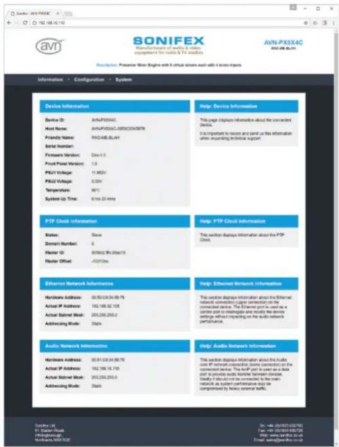
Fig 7-1: Information Web Page
7 Webpages & Local Display Settings (Mix Eng)
Audio Config -> VM Sources Web Page This web page allows the user to setup the virtual mixers on a mix engine. Select the VM wish to change from the VM Select: dropdown list, and then press the edit button associated with the source you wish to setup. This will dialog, where you can select the input source the various parameters that may be associated with it.
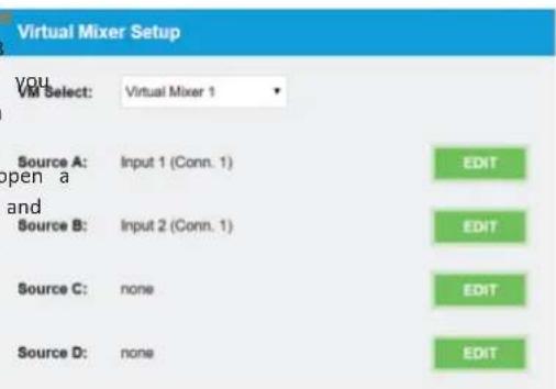
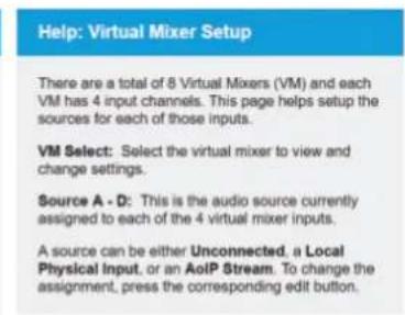
Fig 7-2: Audio Config -> VM Sources Web Page
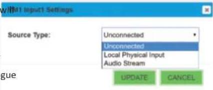
These 3 dialogs show the 3 different source selections available. The first is pretty self-explanatory as the VM source is unused and contain no audio. Levels will continue to be indicated on the MPPR and MPTR but will obviously have no effect on the mixed output.
The second dialog will choose a physical analogue audio input from the back of the mix engine.
There are 3 connectors each with 8 audio inputs7-3: Source Dialog
to choose from - these are imaginatively
numbered 1-24. The actual text here can be changed in the Physical Audio Setup web page to reflect the actual connection
Finally, there is the ability to select AoIP source This lists all the streams that are available on the network and that have been authorised as valid. It is then necessary to select the actual channel that you wish to use from that stream. Most of the time the streams will have a channel count of 2 or 8.
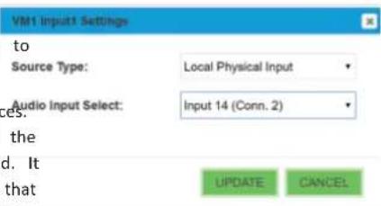
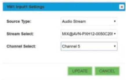
Fig 7-4: Physical Input Dialog Fig 7-5: AoIP Input Dialog
Audio Config -> VM Metering Web Page This web page allows the user to designate the Multicast address to be used for the metering streams that are used by the MPPR and MPTR show the level information on each VM input. The address should be a unique address across the whole AVN system
Virtual Mixer Metering Setup
VM1 Multicast IP Address:
239.1.128.0
VM2 Multicast IP Address:
239.2.128.0
VM3 Multicast IP Address:
239.3.128.0
VM4 Multicast IP Address:
239.4.128.0
VM5 Multicast IP Address:
239.5.128.0
VM6 Multicast IP Address:
239.6.128.0
VM7 Multicast IP Address:
239.7.128.0
VM8 Multicast IP Address:
239.8.128.0
SUBMIT
Fig 7-6: Audio Config -> VM Metering Web Page
Help: Virtual Mixer Metering Setup
The metering information that is provided to the MPPR and MPTR units is sent via IPv4 multicast and is sent separately for each VM. This page allows the user to designate which addresses are used.
VM1 - 8 Multicast IP Address: This sets the IPv4 multicast destination address for the metering data on the corresponding virtual mixer.
Press submit to save the changes to the device.
NOTE: Currently, any changes made here will only take effect after the system has restarted.
7 Webpages & Local Display Settings (Mix Eng
Audio Config -> AoIP Output Streams Web Page
The AoIP Output Streams web page allows the user to specify the type and multicast IP address of the stream outputs generated by the Mix Engine. There are just 2 streams, the first contains 8 channels and consists of the 8 VM mix outputs (VM1 output is channel 1 etc). and the 2 channel stream with the VM outputs selected by the MPTRs. The MPTRs are assigned a device number and channel 1 contains the audio stream being used by device 1 and channel 2 contains stream for device 2. Once again each multicast address
should be unique throughout the AVN system. Fig 7-7: Audio Config -> AoIP Output Streams Web Page
AoIP Output Streams
Source Select:
VM Outputs (8 channels)
DSCP:
Multicast IP
Address:
Stream Name:
AF41
239.69.30.0
VM@AVN-PX8X4C-0050C0345678
SUBMIT
Help: AoIP Output Streams
Source Select: Selects the AoIP source to view and change settings. There are 2 output streams. An 8 channel stream containing the mono output of each VM and a 2 channel stream containing the monitored VM channel for each MPTR.
DSCP: The Differentiated Services Code Point value is used by Diffserv to control the precedence of outgoing AoIP packets for the selected source.
Multicast IP Address: This is the IPv4 multicast destination address for the selected source.
Stream Name: This is the stream name for the selected source that will be visible to other devices on the network. This is currently fixed.
Press submit to save the changes to the device.
Audio Config -> Physical Audio Setup Web Page
The Physical Audio Setup web page allows the user to change the settings for the audio input and outputs on the rear panel of the Mix Eng
Audio Input Settings
Input Channel Select:
ne!Input Name:
Input Enable:
Audio Line Up:
Input 1 (Connector 1)
Input 1 (Conn. 1)

+18dBu = 0dBFS

Audio Output Settings
Output Channel Select:
Output Audio Source:
Audio Line Up:
Output 1 (Connector 1)
VM 1 Output
+18dBu = 0dBFS

SUBMIT
Fig 7-8: Audio Config -> Physical Audio Setup Web Page
Help: Audio Input settings
Input Channel Select: Selects the physical input channel to view and change settings. There are a total of 24 inputs with 8 inputs on each connector.
Input Name: This is the name assigned to the selected input and is used when selecting a source for a particular VM input.
Input Enable: This enables the selected input. Only enabled inputs will be available for VM source selection.
Audio Line Up: Each input has a variable line up which sets the analogue audio level that corresponds to full scale digits in digital levels.
Help: Audio Output Settings
Output Channel Select: Selects the output channel to view and change settings.
Output Audio Source: This selects the audio source for the selected output.
Audio Line Up: Each output has a variable line up which sets the analogue audio level that corresponds to full scale digits in digital levels.
Press submit to save the changes to the device.
7 Webpages & Local Display Settings (Mix Eng
Group Config -> Allowed Devices Web Page
The Allowed Devices web page allows the user to select which devices will be viewable – and therefore selectable – in the other configuration pages. There are filters available to just show a limited set of Presenter Mixer devices.
Adding a device will invoke a dialog where a unit can be selected by discovery or by manually entering the device serial number. The device can also be enabled here or by editing the entry.
Editing a device will give a simple enable/disable option for the MPPR, with an additional option for the MPTR to select the ID (1 or 2) of the device.
Allowed Devices
| Device Type: | Presenter Unit (AVN-MPPR) |
| Device | Serial | Online | G | Enabled |
| GROUP4_1 | 000067 | 192.168.16.137 | 4 | true |
| GROUP2_1 | 000068 | 192.168.16.126 | 2 | true |
| GROUP3_1 | 000063 | 192.168.16.133 | 3 | true |
| GROUP4_3 | 000058 | 192.168.16.139 | 4 | true |
| AVNAMPPR-000054 | 000054 | true | ||
| GROUP2_3 | 000074 | 192.168.16.131 | 2 | true |
| GROUP1_1 | 000075 | true | ||
| GROUP4_0 | 000060 | 192.168.16.136 | 4 | true |
| GROUP2_2 | 000061 | true | ||
| GROUP4_2 | 000057 | 192.168.16.138 | 4 | true |
| AVNAMPPR-000071 | 000071 | true | ||
| GROUP0_0 | 000070 | 192.168.16.132 | 3 | true |
| GROUP1_0 | 000069 | true | ||
| GROUP1_2 | 000062 | true |
Save Device Table
| SAVE DEVICE |
Load Device Table
| Choose File | No file chosen |
| LOAD DEVICE | |
Fig 7-9: Group Config -> Allowed Devices Web Page
Help: Allowed Devices
This is the allowed devices table. The Mix Engine will only communicate with other devices if they exist in this table. Devices can be added either through discovery using Multicast-DNS or manually by entering the unit's serial number.
Device Type: Selects the type of device to show in the allowed devices table.
Allowed Devices Table: The table shows the corresponding list of devices, and specifically for MPPR's, those that will be available for group authorisation.
Device: This will initially contain the unit's ID and serial number but once connected will contain it's friendly name for easier identification.
Serial: The unit's serial number.
Online: When the unit is online this column will display it's IP address.
G: Valid only for Presenter unit's, shows the current group assignment of the unit.
ID: Valid only for Technician unit's, this displays which channel of the MPTR output stream it controls.
Enabled: Enables or disables a device in the table. When it is disabled to device will be ignored.
To add a new device to the table, press the Add button in the table toolbar. After selecting the required settings in the add device dialog, press the Add button to implement the changes.
To change the settings of an existing device, select the entry in the table and press the edit button in the table toolbar. After making the required changes in the edit dialog, press the Update button to implement the changes.
To remove a device from the table, select the entry in the table and press the delete button in the table toolbar.
Help: Save Device Table
The current device table can be written to a local file by clicking the Save Device button.
Help: Load Device Table
The current device table can be overwritten from a previously saved file. Click the select button to locate the required file and then click the Load Device button.
Adding a device will give a dialog with 2 ways of choosing a new device - either by entering the serial number of the part if you know it. The serial number can be read on the back of the unit and is entered as all 7 digits, but without the TL prefix. Alternatively new devices can be discovered, where a list of available connected devices is shown and the user can select the appropriate one. In both cases the device can be enabled or disabled after selection and for the MPTR the unit ID can be selected. Edit AVN-MPPR Device - 000060 Enabled: UPDATE CANCEL
Fig 7-10: Group Config -> Editing a device
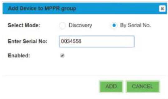
Fig 7-11: Group Config -> Adding a device
7 Webpages & Local Display Settings (Mix Eng
Group Config ->VM Assignment Web Page
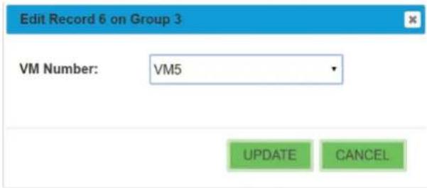
The Group Authorisation web page allows the user to select a group and then to assign the VM that will be used for devices in that group. There are a maximum 128 MPPR devices available and for each of 16 groups, each mix engine they can be assigned a Virtual Mixer or of course remain unassigned. Once a group is controlled or grabbed by a mix engine then then assignment is used to route the virtual mixer audio as long as the MPPR is set to be a member of that group selection switch on the MPPR rear panel. To edit a VM used by a device, first select the group to edited in the dropdown selection at the top of the p, then scroll or page through the device list to the des MPPR.
VM Assignments
| Presenter Devices | Serial | Online | G | VM |
| AVN-MPPR-000054 | 000054 | 0 | ||
| GROUP2_1 | 000058 | 0 | ||
| AVN-MPPR-0083523 | 0083523 | 0 | ||
| GROUP4_1 | 000057 | 0 | ||
| GROUP4_9 | 000050 | 0 | ||
| AVN-MPPR-000063 | 000053 | 192.168.18.140 | 5 | 4 |
| GROUP3_1 | 000053 | 0 | ||
| GROUP2_0 | 000056 | 0 |
Help: VM Assignments
Group Select: Selects the group to show the authorised devices.
VM Assignment Table: The table shows the list of devices that are authorised for the selected group.
To change the settings of an existing device, select the entry in the table and press the edit button in the table toolbar. After making the required changes in the edit dialog, press the Update button to implement the changes.
Fig 7-12: Group Config ->VM Assignment Web Page
Group Config ->Group Assignments Web Page
The Group Assignment web page allows the user to select the 4 active groups to be assigned to Mix Engine from the 16 groups available.
Group Assignments
Group Select:
Studio 3
Group Slot 1: Newsroom
Group Slot 2:
GRAB
RELEASE
RELEASE
RELEASE
RELEASE
Help: Group Assignments
Group Select: Selects the group to be assigned. Press the grab button to assign the selected group to the next available slot. If all 4 slots are currently assigned, the grab button will be disabled.
Group Slot 1 - 4: These show the current group assignments for each slot. To remove the current assignment, press the corresponding release button.
Using both Grab - to add a group to an unused group 3: R + D
and release to free a group from an assigned slot
will cause a double confirmation dialog with the Group Slot 4: Long group alias val
second dialog swapping the Yes No positions to
absolutely ensure that the new group assignment Fig. 7-13: Group Config ->Group Assignments Web Page
is what the user wants. In later software there will
be information about groups that are assigned
elsewhere as the grab function will automatically
remove the group from other mix engines as it is
grabbed locally.
Confirmation Required...
This will grab Studio 3 and assign it to Group Slot 2.
Do you want to continue?
If another Mix Engine is already assigned to a
group it normally is forced to release it when the
user selects a group here, but if the Mix Engine is
disconnected from the network or de-powered
then this cannot happen. Consequently when this
other Mix Engine is connected there will be a clash
as both Mix Engines will want to have control of
the group. In this case the newest Mix Engine will Fig 7.14: Confirmation Dialog
fail to gain control and a message will be shown on
its front panel and the above screen will show
RESOLVE instead of RELEASE. Pressing this will
allow the user to relinquish control of the group or
grab the group and force the other Mix Engine to
relinquish control.
YES
NO
7 Webpages & Local Display Settings (Mix Eng
Group Config ->Group Aliases Web Page The Group Aliases web page allows the user to rename the groups for more easy recognition in group selection dialogs. The group selected is referenced by the MPPR back panel ID 2 Group select rotary switch.
Group Aliases
Group Select:
Group 6
Newsroom2
Group 0:
Group 1:
Group 2:
Group 3: Studio 3
Group 4: Long group alias val
Group 5: Newsroom
Group 6: Group 6
Group 7: Group 7
Group 8: Group 8
Group 9: Group 9
Group A: Group A
Group B: Group B
Group C: Group C
Group D: Group D
Group E: Group E
Group F: Group F

Fig 7-15: Group Config ->Group Aliases Web Page
Help: Group Aliases
Group Select: Selects the group to view and change settings.
Group Alias: This assigns an alias name to the selected group.
Group 0 - F: These show the current group aliases for each group.
Press submit to save the changes to the device.
Misc Settings Web Page
The Misc Setting web page is used to change brightness of the front panel LEDs
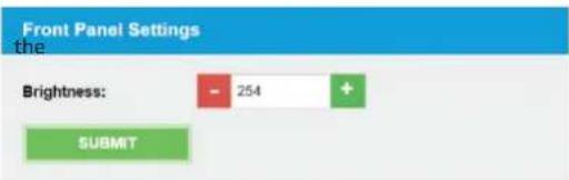
Fig 7-16: Misc Settings Web Page
System Web Page
The system web page allows the user to update the firmware ; to save and load complete configurations from saved files; and to save the system log to a file for examination of fault and conditions. The new firmware will have to be available on the connected PC. These files are downloadable from the Sonifex website – www.sonifex.co.uk and will have an .swu suffix. The upgrade will take around a minute to complete. If the upgrade fails, then there is a fallback recovery system that is permanently available to the unit, which will cause the unit enter a default IP state which can be accessed from a browser at a URL of http://192.168.0.100:8080 Again select the .swu file and click the upgrade button.
The front panel has its own firmware, and this is embedded into the main code above. If the unit starts up an recognises that the front panel code in the firmware is a different version to that currently stored in the front panel then the main board will perform an update on the front panel. It does this by restarting the front panel in a bootstrap mode where the status LEDS 1&2 and 3&4 will flash alternately and where the display will show a progress bar for the update of around 30 seconds. The front panel can be forced into bootstrap mode by holding down the centre ok button and the bottom arrow on the roundel navigation control during a power or reset cycle.
Update Firmware
Please visit our software downloads page for firmware updates.
Current Firmware Version: D1.1.539
Choose File No file chosen
UPDATE
Save Configuration To A File
SAVE CONFIG
Load Configuration From A File
Overwrite Network Settings:
is Choose File No file chosen
LOAD CONFIG
Save System Log To A File
SAVE LOG
Help: Update Firmware
The current firmware version on this unit is shown. Click on the link to visit the Sonifex website to check for new firmware updates.
If an update is available, download the latest file. The file will have the 'SWU' extension. Click the select button to locate the new firmware file and then click Update.
Help: Save Configuration To A File
The current configuration can be written to a local file by clicking the Save Config button.
Help: Load Configuration From A File
The current configuration can be overwritten from a previously saved file. Click Choose file to select the required configuration file and then click the Load Config button.
Help: Save System Log To A File
The System Log records system events which may be useful for resolving configuration issues.
7 Webpages & Local Display Settings (Mix Eng
Mix Engine local screen menu structure
Main Page
- Sys Info Information about the device and firmware
|
- Network Network Settings (for both ports)
| |- Friendly Name Set Friendly Name for unit
| |- Ethernet
| | |- Set Mode Select Dynamic or Static IP Usage
| | |- Set Static IP Address Static IP Address setting
| | |- Set Static Subnet Mask Static Subnet Mask
|
| | - AoIP
| | |- Set Mode Select Dynamic or Static IP Usage
| | |- Set Static IP Address Static IP Address setting
| | |- Set Static Subnet Mask Static Subnet Mask
|
- Display
| |- Contrast    Set Contrast of OLED display
| |- Brightness    Set Brightness of LED indicators
|
- Group Config
| |- Release Group Select a group to be released from the device
| |- Grab Group    Select a group to be added to the device
| |- VM Assign    Selections to change the VM of a device in a group
|
- Close    Close the menu and return to main screen
The display and roundel on the front page allows the user to perform a subset of the functions available on the web pages. It is a little more cumbersome than the web pages as data entry is not as simple without a keyboard, but for an occasional, or emergency change to the setup it is quite usable. The table above shows the structure of the menu screens. The menu is entered by pressing and holding down the roundel centre button – which can be also considered as the enter button – or by pressing the MENU fast key. Use the up and down buttons, or the spinwheel to move to the desired menu selection and then press the enter button. At this level the left button acts like a back key and will move back through the menu structure. And the MENU fast key will exit the menu or sys info and return to the main screen.
Eventually the user will enter either a list of options – with the active option ticked, or will enter a dialog where a parameter can be changed. In a list move the selection to the new choice and press the enter button, followed by moving to the back or close option to exit the list or use the left button to step back along the menu structure. In dialogs the user will have exit options – usually YES/NO or OK/CANCEL use the left and right keys to move between these actions and the press the enter button. If there is a parameter to be changed use the up and down buttons to move between the parameter and the exit options. In the parameter the spinwheel allows the user to change the highlighted element until the setting is correct when a down key followed by the YES or OK option will update the parameter.
The three group config menu selections can be entered directly by pressing the appropriate fast key when the main screen is shown.
8 Webpages (Presenter Remote)
8. Webpages (Presenter Remote)
MPPR web page menu structure
Main Page
- Information Information about the device and firmware
- Configuration Configuration top level menu
  | - Network Network Settings (for both ports)
  | - PTP Profiles PTP Settings
  | - Misc Settings Miscellaneous settings
- System Firmware and configuration file update page
All but the Misc Settings web page on the MPPR
have similar functions and controls to the Mix Engine as shown above.
Misc Settings Web Page
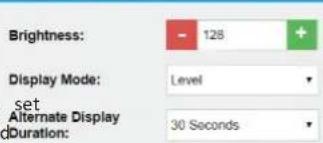
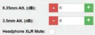
The Misc Settings web page allows the user to set the brightness and LED knob display options and duration: to set the audio attenuation to be applied to the 2 types of jack socket (1/4inch and 3.5mm) on the front panel.
Front Panel Settings
Help: Front Panel Settings
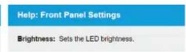
Brightness: Sets the LED brightness.
Display Mode: Sets the default mode of the LEDs around the rotary controls.
Alternate Display Duration: This sets the period the metering is shown in level display mode, or the volume level is shown in metering display mode, when a control is clicked.
Audio Settings
Help: Audio Settings
6.35mm Att. (dB): Sets the attenuation of the 6.35mm jack on the front of the unit. Value is an integer between 0 and 24 dB.
3.5mm Att. (dB): Sets the attenuation of the 3.5mm jack on the front of the unit. Value is an integer between 0 and 24 dB.
Headphone XLR Mute: Sets whether to mute the rear panel XLR output, when headphones are connected to one of the front panel sockets.
Press submit to save the changes to the device.
Fig 7-18: Misc Settings Web Page
System Web Page
The system web page allows the user to update the firmware ; to save and load complete configurations from saved files; and to save the system log to a file for examination of fault and conditions. The new firmware will have to be available on the connected PC. These files are downloadable from the Sonifex website - www.sonifex.co.uk and will have an .swu suffix. The upgrade will take around a minute to complete. If the upgrade fails, then there is a fallback recovery system that is permanently available to the unit, which will cause the unit to enter a default IP state which can be accessed from a browser at a URL of http://192.168.0.100:8080 Again select the .swu file and click the upgrade button.
The front panel has its own firmware, and this is embedded into the main code above. If the unit starts up an recognises that the front panel code in the firmware is a different version to that currently stored in the front panel then the main board will perform an update on the front panel. It does this by restarting the front panel in a bootstrap mode where the encoder knobs 1&2 and 3&4 will flash alternately and where the VM select LEDS will show the progress for the update of around 30 seconds. The front panel can be forced into bootstrap mode by holding down the encoder knobs 1 & 3 during a power or reset cycle.
9. Webpages & Local Display Settings (Technician Remote)
MPTR web page menu structure
Main Page
- Information Information about the device and firmware
- Configuration Configuration top level menu
  | - Network Network Settings (for both ports)
  | - Misc Settings Miscellaneous settings
- System Firmware and configuration file update page
All but the Misc Settings web page on the MPTR have similar functions and controls to the Mix Engine as shown above.
Misc Settings Web Page
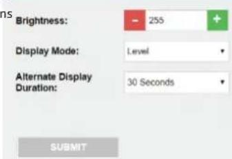
The Misc Settings web page allows the user to set the brightness and LED knob display options on the front panel
Front Panel Settings
Help: Front Panel Settings
Brightness: Sets the LED brightness.
Display Mode: Sets the default mode of the LEDs around the rotary controls.
Alternate Display Duration: This sets the period the metering is shown in level display mode, or the volume level is shown in metering display mode, when a control is clicked.
Press submit to save the changes to the device.
Fig 7-19: Misc Settings Web Page
System Web Page
The system web page allows the user to update the firmware; to save and load complete configurations from saved files; and to save the system log to a file for examination of fault and conditions. The new firmware will have to be available on the connected PC. These files are downloadable from the Sonifex website – www.sonifex.co.uk and will have an .swu suffix. The upgrade will take around a minute to complete. If the upgrade fails, then there is a fallback recovery system that is permanently available to the unit, which will cause the unit to enter a default IP state which can be accessed from a browser at a URL of http://192.168.0.100:8080 Again select the .swu file and click the upgrade button.
The front panel has its own firmware, and this is embedded into the main code above. If the unit starts up an recognises that the front panel code in the firmware is a different version to that currently stored in the front panel then the main board will perform an update on the front panel. It does this by restarting the front panel in a bootstrap mode where the encoder knobs 1&2 and 3&4 will flash alternately and where the VM select buttons and the display will show a progress bar for the update of around 30 seconds. The front panel can be forced into bootstrap mode by holding down the encoder knobs 1 & 3 during a power or reset cycle.
9 Webpages & Local Display Settings (Technician Remo
MPTR local screen menu structure
Main Page
|- Sys Info Information about the device and firmware
|
|- Network Network Settings (for both ports)
| |- Friendly Name Set Friendly Name for unit
| |- Ethernet
| | |- Set Mode Select Dynamic or Static IP Usage
| | |- Set Static IP Address Static IP Address setting
| | |- Set Static Subnet Mask Static Subnet Mask
|
|- Display
| |- Contrast Set Contrast of OLED display
| |- Brightness Set Brightness of LED indicators
|
|- Group Config
| |- Release Group Select a group to be released from the device
| |- Grab Group Select a group to be added to the device
| |- VM Assign Selections to change the VM of a device in a group
|
|- Close Close the menu and return to main screen
The MPTR menu options have similar functions and identical controls to the Mix Engine as shown above.
10. Technical Specifications
AVN-PX8x4C Audio Inputs - Gain setting 0dBFS = +18dBu unless otherwise stated
Parameter Line Input
Input Impedance >20kΩ balanced
0dBFS line-up +15/+18/+20/+22/+24dBu Balanced*
Frequency Response 20Hz to 20kHz, +0/-0.2dB
THD+N <-110dBFS, -30dBFS, 20Hz to 20kHz, All input gain settings, 20kHz BW
Noise -110dBFS, 20kHz BW, Rs=200Ω
Crosstalk <-100dB
Common Mode Rejection >70dB @ 1kHz, All input gain settings
AVN-PX8x4C Audio Outputs - Gain setting 0dBFS = +18dBu unless otherwise stated
Parameter Line Output
Output Impedance <50Ω balanced
0dBFS line-up +15/+18/+20/+22/+24dBu Balanced*
Frequency Response 20Hz to 20kHz, +0/-0.5dB
THD+N <-110dBFS, -30dBFS, 20Hz to 20kHz, All input gain settings, 20kHz BW
Noise -110dBFS, 20kHz BW, Rs=200Ω
AVN-MPPR Audio Output - Gain setting 0dBFS = +18dBu unless otherwise stated
Parameter Line Output Headphone Output
Output Impedance <50Ω balanced Drives 150mW into 8Ω to 600Ω headphones
0dBFS line-up +15/+18/+20/+22/+24dBu Balanced* +20dBu Maximum when no attenuation factor applied.
Frequency Response 20Hz to 20kHz, +0/-0.5dB 20Hz to 20kHz, +0/-0.2dB
THD+N <-110dBFS, -30dBFS, 20Hz to 20kHz,
All input gain settings, 20kHz BW <-108dBFS, -30dBFS, 20Hz to 20kHz, unity gain, 20kHz BW
Noise -110dBFS, 20kHz BW, Rs=200Ω -110dBFS, 20kHz BW
*+18dB, +22dB and +24dB are handled in hardware, +15dB and +20dB in DSP
AVN-PX8x4C Power - Dual redundant IEC 85 - 264VAC 47 - 63Hz Max 60W 2Amp Fused type T 2A L
AVN-MPPR PoE Power- Standard 802.3af, Class 3, PD Power Range 6.49W to 12.95W, Typical PSE Power Usage 14W, Max PSE Power Usage 15.4W
AVN-MPTR PoE Power - Standard 802.3af, Class 3, PD Power Range 0.44W to 12.94W, Typical PSE Power Usage 7W, Max PSE Power Usage 15.4W
Network Capability - 10/100/1000BASE-T IEEE 802.3 compliant, Automatic MDI/MDIX crossover
SFP Type - SGMII, 1000BASE-X & 100BASE-FX Media support for both Copper and fibre SFP modules
Network Requirements - IEEE1588-2008, IGMP, QoS (DiffServ)
Notes
Notes
SONIFEX
w w w . s o n i
t:+44 (0)1933 650 700
f:+44 (0)1933 650 726
sales@sonifex.co.uk
f e x . c o . u k
- Presenter Mixer System Handboc
- Contents
- SONIFEX
- Register Online for an Extended 2 Year Warranty
- Warranty
- Sonifex Warranty & Liability Terms & Conditions
- Definitions
- ds In Unpacking Your Product
- Item Quantity
- Repairs & Returns
- CE Conformity
- i on and Safety & Installation of Mains Operated Equipment
- Voltage Setting Checks
- Fuse Rating
- Power Cable & Connection
- Safety & Installation
- WEEE Directive
- Atmosphere/Environment
- Sonifex Presenter Mixer System Manual
- Overview
- AVN-PX8x4C Mix Engine Rack
- AVN-PX8x4C Mix Engine Rack
- Front Panel Controls
- OLED Display
- Menu fast keys
- ation Power button
- Reset button
- Rear Panel Connections
- Standard GPIO Connector
- Analogue Audio Inputs & Outputs
- Audio Levels and dBFS equivalences
- AVN-MPPR Presenter Remote Unit
- AVN-MPPR Presenter Remote Unit
- Rotary Controls
- Metering Mode
- Virtual Mixer Assignment
- Headphone sockets
- XLR Mute
- Attenuation
- ToPentebutton
- IP address reset
- Rear Panel
- Network Connector
- Mix Output Mono Analogue Output
- Hardware ID Settings
- Mounting the AVN-MPPR Presenter Remote Unit
- AVN-MPTR Technician Remote Unit
- Status LEDs
- AVN-MPTR Technician Remote Unit
- Mixer Selection buttons
- GPO and Enable button
- Third Party API
- Third Party API
- Operational Specification
- Startup
- Authorisation
- Control Precedence
- Operational Specification
- Group/Studio Assignment
- Operational Specification 6
- Configuration
- Webpages & Local Display Settings (Mix Engine)
- Information Web Page
- Webpages & Local Display Settings (Mix Eng)
- Virtual Mixer Metering Setup
- Help: Virtual Mixer Metering Setup
- Webpages & Local Display Settings (Mix Eng
- AoIP Output Streams
- Help: AoIP Output Streams
- Audio Input Settings
- Audio Output Settings
- Help: Audio Input settings
- Help: Audio Output Settings
- Help: Allowed Devices
- Help: Save Device Table
- Help: Load Device Table
- Group Config ->VM Assignment Web Page
- Help: VM Assignments
- Group Config ->Group Assignments Web Page
- Group Assignments
- Help: Group Assignments
- Confirmation Required...
- Group Aliases
- Help: Group Aliases
- System Web Page
- Update Firmware
- Save Configuration To A File
- SAVE CONFIG
- Load Configuration From A File
- Save System Log To A File
- SAVE LOG
- Help: Update Firmware
- Help: Save Configuration To A File
- Help: Load Configuration From A File
- Help: Save System Log To A File
- Webpages (Presenter Remote)
- Webpages (Presenter Remote)
- Help: Front Panel Settings
- Help: Audio Settings
- Webpages & Local Display Settings (Technician Remote)
- Misc Settings Web Page
- Technical Specifications
Brand : Sonifex
Model : AVN-PX8
Category : Hand blender