S1 - Hand blender Sonifex - Free user manual and instructions
Find the device manual for free S1 Sonifex in PDF.


| Product Type | Hand Blender (Immersion Blender) |
| Brand | Sonifex |
| Model | S1 |
| Power | 400 W |
| Voltage | 220-240 V |
| Speed Settings | 2 speeds + Turbo function |
| Blade Material | Stainless Steel |
| Shaft Length | 20 cm |
| Weight | 1.2 kg |
| Dimensions (approx.) | 40 x 10 x 10 cm |
| Cord Length | 1.5 m |
| Housing Material | Plastic |
| Safety Features | Overheat protection, automatic shut-off |
| Dishwasher Safe Parts | Blade shaft and mixing jar |
| Cleaning | Wipe motor body with damp cloth; rinse blade under water |
| Warranty | 2 years |
| Included Accessories | Mixing jar, whisk attachment (optional) |
Frequently Asked Questions - S1 Sonifex
User questions about S1 Sonifex
0 question about this device. Answer the ones you know or ask your own.
Ask a new question about this device
Download the instructions for your Hand blender in PDF format for free! Find your manual S1 - Sonifex and take your electronic device back in hand. On this page are published all the documents necessary for the use of your device. S1 by Sonifex.
USER MANUAL S1 Sonifex
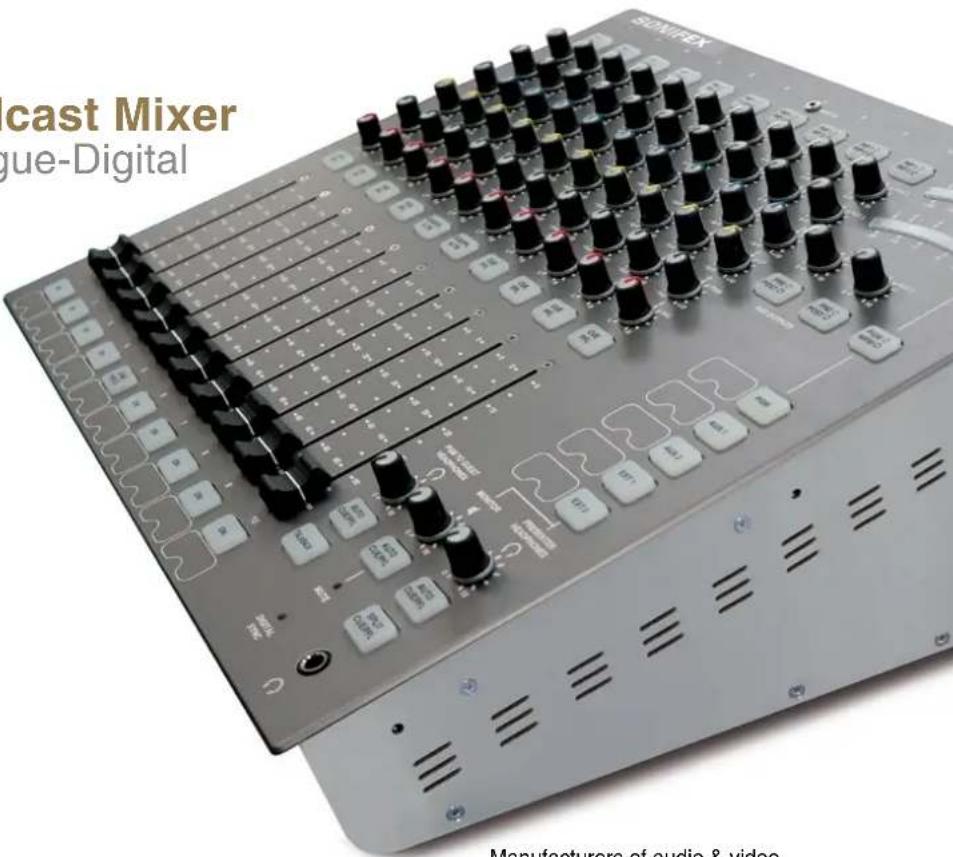
Radio Broadcast Mixer
HANDBOOK
S1 Radio Broadcast Mixer
10 Channel Analogue-Digital
Manufacturers of audio & video products for radio & TV broadcasters
SONIFEX
S1 Handbook
For the latest Sonifex handbook information please visit the Sonifex website at www.sonifex.co.uk
This handbook is for use with the following product:
S1 Radio Broadcast Mixer, 10 Channel Analogue-Digital
AW10777
Stock Code: 30-172
Revision 1.05, July 2020
©Sonifex Ltd, 2020
All Rights Reserved
Sonifex Ltd, 61, Station Road, Irthlingborough,
Northants, NN9 5QE, England.
Tel: +44 (0)1933 650 700
Fax: +44 (0)1933 650 726
Email: sales@sonifex.co.uk
Website: http://www.sonifex.co.uk
Information in this document is subject to change without notice and does not represent a commitment on the part of the vendor. Sonifex Ltd shall not be liable for any loss or damage whatsoever arising from the use of information or any error contained in this manual.
No part of this manual may be reproduced or transmitted in any form or by any means, electronic or mechanical, including photocopying, recording, information storage and retrieval systems, for any purpose other than the purchaser's personal use, without the express written permission of Sonifex Ltd. Unless otherwise noted, all names of companies, products and persons contained herein are part of a completely fictitious adaptation and are designed solely to document the use of Sonifex product.
Made in the UK by SONIFEX
Contents
Product Warranty - 2 Year Extended i
Sonifex Warranty & Liability Terms & Conditions i
Unpacking Your Product ii
Repairs & Returns iii
CE Conformity iii
Safety & Installation of Mains Operated Equipment iii
Voltage Setting Checks iii
Fuse Rating iii
Power Cable & Connection iii
WEEE Directive iv
Atmosphere/Environment iv
1 Introduction 1
Innovative Design 1
Superb Audio Quality & Unquestionable Reliability 1
Installation Notes 2
2 User Guide 5
User Guide – Section 2-1 5
User Guide – Section 2-2 Input Channels 7
User Guide – Section 2-3 Front Panel Channel Features 8
User Guide – Section 2-4 Metering and Monitors 11
Monitor and Headphone Controls 12
Meter Controls 13
User Guide – Section 2-5 Output Buses 13
Auxiliary Outputs 14
3 Mixer Applications 16
Presenter Controlled Studio 16
Producer Controlled Studio With Separate Presenter 18
User Guide – Section 2-3 Making the most of auxiliary outputs 19
User Guide – Section 3-4 External equipment and the S1 20
Telephone hybrid 20
4 Advanced Configurations 22
User Guide – Section 4-1 Using the Remote Control 22
User Guide – Section 4-2 General purpose inputs
and outputs 23
User Guide – Section 4-3 SCi and the S1 24
SCi for S1 24
Channel Configuration 25
GPIO Configuration 27
Contents & Figures
System configuration 28
Talkback Setup Box 29
Information & Updates 29
RS-232 indicators 30
Options menu 30
5 Connectors and Cabling 31
Connector Pin Outs 32
6 Technical Specification 35
7 Default Settings 37
8 Serial Communication Protocol 39
Serial Data Format 39
Remote Control Commands 39
9 Glossary 46
Figures
Fig 1-1: S1 Top View 1
Fig 1-2: Dimensions & Cut-Out Sizes For S1 Mixer 3
Fig 1-3: S1 Mixer Rear View 3
Fig 1-4: S1 Mixer Top View 4
Fig 2-1: input Stages 5
Fig 2-2: Output & Power Board 6
Fig 2-3: Main Mix Stage 6
Fig 2-4: Monitors 7
Fig 2-5: Channels 1 and 2 Mic / Line Inputs 7
Fig 2-6: Channels 3 and 4 - Mic / Mono Line / Stereo Line Inputs 7
Fig 2-7: Channel 5 - Mic / Telco Input 7
Fig 2-8: Channel 6 – Stereo Line / Stereo Cleanfeed Input 8
Fig 2-9: Channel 7 and 8 - Stereo Line / RCA Inputs 8
Fig 2-10: Channel 9 and 10 - Stereo Line / Digital Inputs 8
Fig 2-11: External Inputs 8
Fig 2-12: Input Selection 8
Fig 2-13: DROP-IN Jack 8
Fig 2-14; AUX Controls 9
Fig 2-15: Equalisation Controls 9
Fig 2-16: TRIM Control 9
Fig 2-17: PAN Control 9
Fig 2-18: Balance Control 9
Fig 2-19: CUE/PFL Selection 9
Fig 2-20: CUE/PFL & T/B Selection 10
Fig 2-21: ON Selection 10
Fig 2-21B: LINE HOLD 10
Fig 2-22: Scribble Pad 10
Fig 2-23: Fader 11
Fig 2-24: Monitor and headphone sockets 11
Fig 2-25: Presenter & Guest Headphones Connector 11
Fig 2-26: Level controls 12
Fig 2-27: Program/ Meters Follow Monitors 13
Fig 2-28: PPM / VU 13
Fig 2-29: PGM Output 13
Fig 2-30: Cleanfeed Outputs 13
Fig 2-31: Digital Outputs 14
Fig 2-32: Lock Indicator 14
Fig 2-33: Stereo Aux Outputs 14
Fig 2-34: Auxiliary master gain and PRE / POST Selection 14
Fig 3-1a: Presenter In Studio - External Equipment Connections 16
Fig 3-1b: Presenter In Studio - Telephone Line Connections 17
Fig 3-1c: Presenter In Studio - Presenter and Guest Connections 17
Fig 3-2a: Presenter And Producer In Control Room - External
Equipment Connections 18
Fig 3-2b: Presenter And Producer In Control Room -
Telephone Line Connections 18
Fig 3-2c: Presenter And Producer In Control Room -
Presenter and Guest Connections 19
Fig 3-3: On-Air Light 21
Fig 4-1: RS-232 Serial Port 24
Fig 4-2: SCi Launcher 24
Fig 4-3: Main Screen 24
Fig 4-4: Channel Configuration Screen 25
Fig 4-5: GPIO Configuration Screen 27
Fig 4-6: System Configuration Screen 28
Fig 4-7: Information & Updates Screen 29
Fig 5-1: XLR 3 Pin Connectors 31
Fig 5-2: RCA Phono Connector 31
Fig 5-3: BNC Connector 31
Fig 5-4; 6.35mm 'A' Gauge Stereo Jack Plugs 31
Fig 5-5: D Type Connectors 32
Warranty Registration
SONIFEX
Register Online for an Extended 2 Year Warranty
As standard, Sonifex products are supplied with a 1 year back to base warranty.
If you register the product online, you can increase your product warranty to 2 years and we can also keep you informed of any product design improvements or modifications.
Product: ____ Serial No: ____
To register your product, please go online to www.sonifex.co.uk/register
Product Warranty - 2 Year Extended
As standard, Sonifex products are supplied with a 1 year back to base warranty. In order to register the date of purchase and so that we can keep you informed of any product design improvements or modifications, it is important to complete the warranty registration online. Additionally, if you register the product on the Sonifex website, you can increase your product warranty to 2 years. Go to the Sonifex website at: http://www.sonifex.co.uk/technical/register/index.asp to apply for your 2 year warranty.
Note: For your own records the product serial number is recorded on the CE certification page of this handbook.
Sonifex Warranty & Liability Terms & Conditions
1. Definitions
'the Company' means Sonifex Ltd and where relevant includes companies within the same group of companies as Sonifex Limited.
'the Goods' means the goods or any part thereof supplied by the Company and where relevant includes: work carried out by the Company on items supplied by the Purchaser; services supplied by the Company; and software supplied by the Company.
'the Purchaser' means the person or organisation who buys or has agreed to buy the Goods.
'the Price' means the Price of the Goods and any other charges incurred by the Company in the supply of the Goods.
'the Warranty Term' is the length of the product warranty which is usually 12 months from the date of despatch; except when the product has been registered at the Sonifex website when the Warranty Term is 24 months from the date of despatch.
'the Contract' means the quotation, these Conditions of Sale and any other document incorporated in a contract between the Company and the Purchaser.
This is the entire Contract between the parties relating to the subject matter hereof and may not be changed or terminated except in writing in accordance with the provisions of this Contract. A reference to the consent, acknowledgement, authority or agreement of the Company means in writing and only by a director of the Company.
2. Warranty
a. The Company agrees to repair or (at its discretion) replace Goods which are found to be defective (fair wear and tear excepted) and which are returned to the Company within the Warranty Term provided that each of the following are satisfied:
i. notification of any defect is given to the Company immediately upon its becoming apparent to the Purchaser;
ii. the Goods have only been operated under normal operating conditions and have only been subject to normal use (and in particular the Goods must have been correctly connected and must not have been subject to high voltage or to ionising radiation and must not have been used contrary to the Company's technical recommendations);
iii. the Goods are returned to the Company's premises at the Purchaser's expense;
iv. any Goods or parts of Goods replaced shall become the property of the Company;
v. no work whatsoever (other than normal and proper maintenance) has been carried out to the Goods or any part of the Goods without the Company's prior written consent;
Warranty
vi. the defect has not arisen from a design made, furnished or specified by the Purchaser;
vii. the Goods have been assembled or incorporated into other goods only in accordance with any instructions issued by the Company;
viii. the defect has not arisen from a design modified by the Purchaser;
ix. the defect has not arisen from an item manufactured by a person other than the Company. In respect of any item manufactured by a person other than the Company, the Purchaser shall only be entitled to the benefit of any warranty or guarantee provided by such manufacturer to the Company.
b. In respect of computer software supplied by the Company the Company does not warrant that the use of the software will be uninterrupted or error free.
c. The Company accepts liability:
(i) for death or personal injury to the extent that it results from the negligence of the Company, its employees (whilst in the course of their employment) or its agents (in the course of the agency);
(ii) for any breach by the Company of any statutory undertaking as to title, quiet possession and freedom from encumbrance.
d. Subject to conditions (a) and (c) from the time of despatch of the Goods from the Company's premises the Purchaser shall be responsible for any defect in the Goods or loss, damage, nuisance or interference whatsoever consequential economic or otherwise or wastage of material resulting from or caused by or to the Goods. In particular the Company shall not be liable for any loss of profits or other economic losses. The Company accordingly excludes all liability for the same.
e. At the request and expense of the Purchaser the Company will test the Goods to ascertain performance levels and provide a report of the results of that test. The report will be accurate at the time of the test, to the best of the belief and knowledge of the Company, and the Company accepts no liability in respect of its accuracy beyond that set out in Condition (a).
f. Subject to Condition (e) no representation, condition, warranty or other term, express or implied (by statute or otherwise) is given by the Company that the Goods are of any particular quality or standard or will enable the Purchaser to attain any particular performance or result, or will be suitable for any particular purpose or use under specific conditions or will provide any particular capacity, notwithstanding that the requirement for such performance, result or capacity or that such particular purpose or conditions may have been known (or ought to have been known) to the Company, its employees or agents.
g. (i) To the extent that the Company is held legally liable to the Purchaser for any single breach of contract, tort, representation or other act or default, the Company's liability for the same shall not exceed the price of the Goods.
(ii) The restriction of liability in Condition (g)(i) shall not apply to any liability accepted by the Seller in Condition (c).
h. Where the Goods are sold under a consumer transaction (as defined by the Consumer Transactions (Restrictions on Statements) Order 1976) the statutory rights of the Purchaser are not affected by these Conditions of Sale.
Unpacking Your Product
Each product is shipped in protective packaging and should be inspected for damage before use. If there is any transit damage take pictures of the product packaging and notify the carrier immediately with all the relevant
details of the shipment. Packing materials should be kept for inspection and also for if the product needs to be returned.
The product is shipped with the following equipment so please check to ensure that you have all of the items below. If anything is missing, please contact the supplier of your equipment immediately.
Item
Quantity
Product unit 1
IEC mains lead fitted with moulded mains plug 1
Handbook and warranty card 1
GSM stubby antenna 1
If you require a different power lead, please let us know when ordering the product.
Repairs & Returns
Please contact Sonifex or your supplier if you have any problems with your Sonifex product. Email technical.support@sonifex.co.uk for the repair/ upgrade/returns procedure, or for support & questions regarding the product operation.
CE Conformity
The products in this manual comply with the essential requirements of the relevant European health, safety and environmental protection legislation.
The technical justification file for this product is available at Sonifex Ltd.
The declaration of conformity can be found at: http://www.sonifex.co.uk/declarations
Safety & Installation of Mains Operated Equipment
There are no user serviceable parts inside the equipment. If you should ever need to look inside the unit, always disconnect the mains supply before removing the equipment covers. The cover is connected to earth by means of the fixing screws. It is essential to maintain this earth/ground connection to ensure a safe operating environment and provide electromagnetic shielding.
Voltage Setting Checks
Ensure that the machine operating voltage is correct for your mains power supply by checking the box in which your product was supplied. The voltage is shown on the box label. The available voltage settings are 115V, or 230V. Please note that all products are either switchable between 115V and 230V, or have a universal power supply.
Fuse Rating
The product is supplied with a single fuse in the live conducting path of the mains power input. For reasons of safety it is important that the correct rating and type of fuse is used. Incorrectly rated fuses could present a possible fire hazard, under equipment fault conditions. The active fuse is fitted on the outside rear panel of the unit.
Power Cable & Connection
An IEC power connector is supplied with the product which has a moulded plug attached.
The mains plug or IEC power connector is used as the disconnect device. The mains plug and IEC power connector shall remain readily operable to disconnect the apparatus in case of a fault or emergency.
The mains lead is automatically configured for the country that the product is being sent to, from one of:
Safety & Installation
Territory Voltage IEC Lead Type Image
| UK & Middle East 230V UK 3 pin to IEC lead | |
| Europe 230V | European Schuko round 2 pin to IEC lead |
| USA, Canada and South America | 115V 3 flat pin to IEC lead |
| Australia & New Zealand | 230V Australasian 3 flat pin to IEC lead |
Connect the equipment in accordance with the connection details and before applying power to the unit, check that the machine has the correct operating voltage for your mains power supply.
This apparatus is of a class I construction. It must be connected to a mains socket outlet with a protective earthing connection.
Important note: If there is an earth/ground terminal on the rear panel of the product then it must be connected to Earth.
WEEE Directive

The Waste Electrical and Electronic Equipment (WEEE) Directive was agreed on 13 February 2003, along with the related Directive 2002/95/EC on Restrictions of the use of certain Hazardous Substances in electrical and electronic
equipment (RoHS). The Waste Electrical and Electronic Equipment Directive (WEEE) aims to minimise the impacts of electrical and electronic equipment on the environment during their life times and when they become waste. All products manufactured by Sonifex Ltd have the WEEE directive label placed on the case. Sonifex Ltd will be happy to give you information about local organisations that can reprocess the product when it reaches its "end of use", or alternatively all products that have reached "end of use" can be returned to Sonifex and will be reprocessed correctly free of charge.
Atmosphere/Environment
This apparatus should be installed in an area that is not subject to excessive temperature variation (<0°C, >50°C), moisture, dust or vibration.
This apparatus shall not be exposed to dripping or splashing, and no objects filled with water, such as vases shall be placed on the apparatus.
1 Introduction
The Sonifex S1 Mixer is a compact, low cost, fixed format radio on-air mixing console designed to cater for a wide and far reaching broadcast market. On the surface, it is simple and easy to use but it also has hidden layer of variety and flexibility for those who like to get into the heart of their products, tweak the engine so to speak. Using the latest technology components, S1 offers digital audio quality with analogue reliability. S1 has both digital and analogue input channels, together with simultaneous analogue and digital outputs.
Innovative Design
- The S1 can be rackmounted or used as a desktop mixer
- The back panel connections can be rotated onto the back of the unit or onto the base of the unit
- Large back-lit buttons allow you to see the status of the mixer at all times.
Superb Audio Quality & Unquestionable Reliability
- The S1 uses the latest semiconductor technology to allow input of SPDIF & Toslink digital audio signals up to 24bit, 192kHz, and the output of AES/EBU and S/PDIF digital audio signals up to 24 bit, 96kHz sample rate.
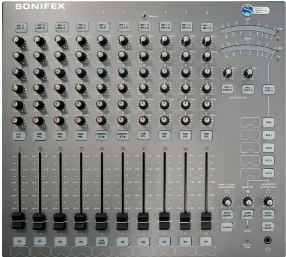
Fig 1-1: S1 Top View
1 Introduction
- The analogue signal paths use low noise circuitry to provide superb audio performance well capable of satisfying radio listeners worldwide.
- The high reliability and build quality of the S1 minimises the chance of failure, avoiding lost air-time.
- ALPS long-throw 100mm faders give a smooth, repeatable response and the XLR Neutrik connectors used are an industry standard.
- The use of VCA's controlled by the faders ensures tight stereo tracking and eliminates mechanical and electronic noise.
- The S1 has an internal power supply providing regulated, ripple-free power, to the mixer.
• High quality anodised aluminium is used for the chassis to...
Progress
Following on from the Sonifex Sovereign range of audio mixers, the S1 combines all the features needed of a radio broadcast mixer in a stylish, flush-mounting chassis: a wide range of input and output channels, CUE/PFL, fader-start operation of equipment, automatic monitor muting on mic-live, light switching remote outputs, EQ on input modules, two auxiliary buses, two external inputs and a main program audio bus.
Flexible
The S1 is a highly configurable unit and has been designed to be jumper free, allowing the user to alter the configuration quickly whilst still on air rather than having to take apart the unit armed with a pair of tweezers and a magnifying glass. The majority of the desk can be setup and controlled using the Sonifex SCI Software. This opens up a world of options:
- Producer Controlled Environment – SCi allows the producer or engineer to control all settings and parameters reducing the required skill set of the Presenter and leaving them to focus on their broadcast.
-
Remote Control – Control external equipment using the dedicated remote control ports. These are great for starting or stopping CD players and other external equipment and are fully configurable to suit most manufacturers and remove limitations.
-
Global Talkback – Allow all your guests to hear each other through their headphones, alleviating the risk of Mic/ Headphone feedback. (for more details refer to page 19.
- Automation Tally – Give a visual indication of an impending event to a presenter using the versatile GPIO system.
- Many more examples covered in the user setup section.
Installation Notes
Atmosphere
The S1 mixer should be installed in an area which is not subject to excessive heat or cold. Also, you should avoid installing it in atmospheric conditions which are dusty, smoky, or dirty, or where there is moisture or vibration. Do not use any liquids to clean the fascia of the mixer: a soft dry brush is ideal. Use a clean cloth moistened with water or ethyl alcohol to clean the trim and scribble pads. Other solvents may cause damage to paint or plastic parts.
Electromagnetic Radiation
Avoid using the S1 mixer close to strong sources of electromagnetic radiation such as, video monitors or high power electric cabling. This may cause degradation of the audio quality due to induced voltages in connecting leads and chassis. In all cases the S1 mixer should be installed and serviced by qualified personnel.
Dimensions and Cut-Out Sizes
The cut-out size is for reference only and should be checked with your mixer.
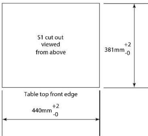
Fig 1-2: Dimensions & Cut-Out Sizes For S1 Mixer
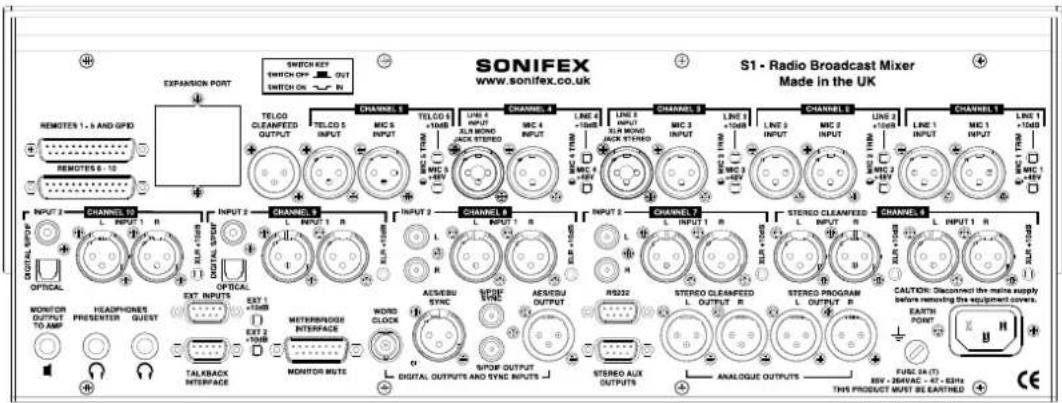
Fig 1-3: S1 Mixer Rear View
1 Introduction
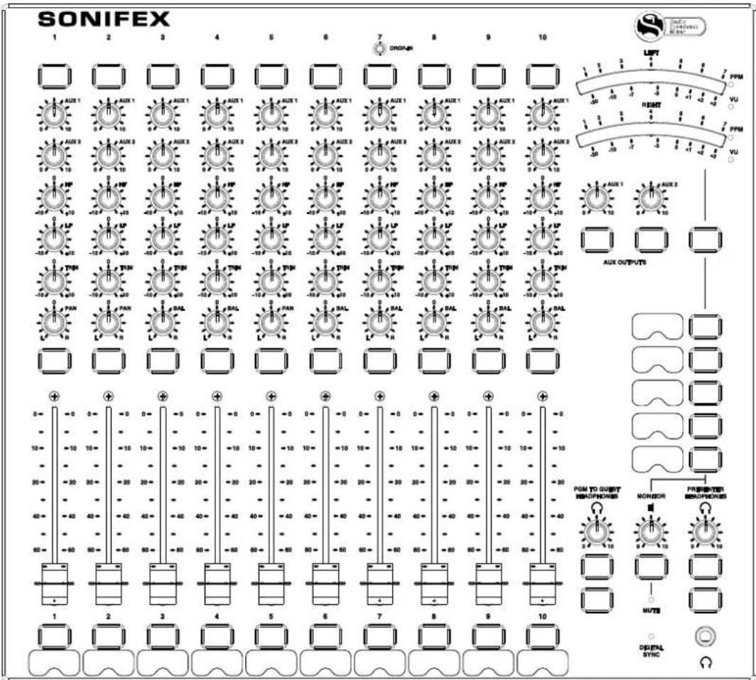
Fig 1-4: S1 Mixer Top View
2 User Guide
Getting to know your mixer
The following section will display and explain the features of S1 Mixer from input through to output. Please read this section thoroughly to acquaint yourself thoroughly with the myriad of options available. However, if you are more interested in setting it up skip to the next chapter - Mixer Applications.
The following section is divided into these parts:
- System block diagrams – If you are electronically inclined, dive into the inner workings of the S1.
- Input channel types – Discover the type of Inputs available to you. Page 7.
- Front panel channel features – All channel knobs and buttons explained. Page 8.
- Metering, monitors and headphones – Explore the Metering options and find out where to plug in your monitors and stick your headphone jack. Page 12.
- Output buses – Understand all the output options you have. Page 13.
User Guide – Section 2-1
System Block Diagrams
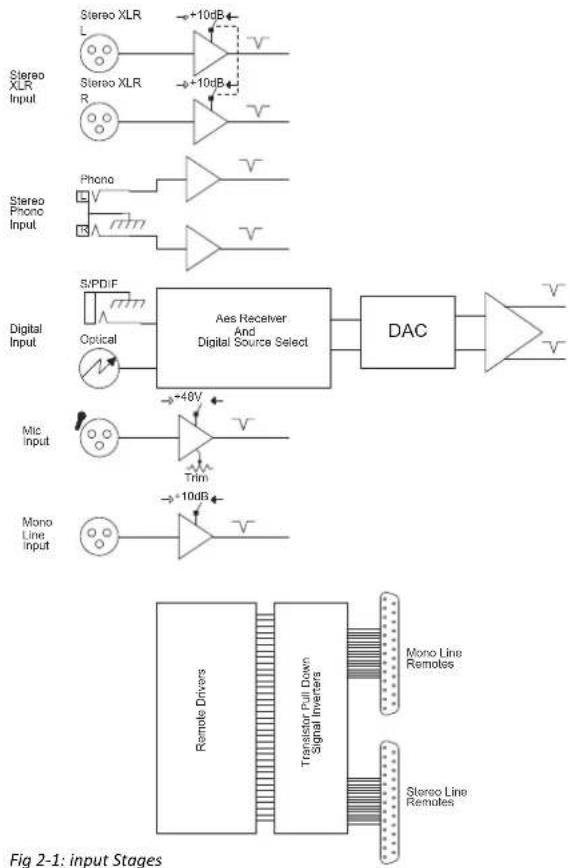
flowchart
graph TD
    A["Stereo XLR Input"] --> B["+10dB"]
    C["Stereo XLR R"] --> D["+10dB"]
    E["Phono"] --> F["+48V"]
    G["Digital Input"] --> H["Aes Receiver And Digital Source Select"]
    I["Mic Input"] --> J["+48V"]
    K["Mono Line Input"] --> L["+10dB"]
    M["Remote Drivers"] --> N["Transistor Pull Down Signal Inverters"]
    O["Mono Line Remotes"] --> P["+10dB"]
    Q["Stereo Line Remutes"] --> R["+10dB"]
    S["+10dB"] --> T["DAC"]
    U["+10dB"] --> V["Output Stage"]
2 User Guide
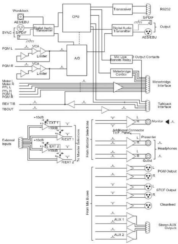
flowchart
graph TD
    subgraph External Inputs
        A["Wordclock"] --> B["Digital Audio Transceiver"]
        C["AES/EBU"] --> B
        D["SYNC"] --> B
        E["S/PDIF"] --> B
        F["PGM L"] --> G["Limiter"]
        H["PGM R"] --> I["Limiter"]
        J["Meter L"] --> K["VCA"]
        L["Meter R"] --> M["VCA"]
        N["PFL L"] --> O["Limiter"]
        P["PFL R"] --> Q["VCA"]
        R["PGM L"] --> S["VCA"]
        T["PGM R"] --> U["Limiter"]
    end

    subgraph External Inputs
        V["External Inputs"] --> W["+10dB"]
        X["TBOUT"] --> Y["+10dB"]
        Z["To Monitor Selections"] --> AA["+10dB"]
        AB["To Monitor Selections"] --> AC["+10dB"]
        AD["To Monitor Selections"] --> AE["+10dB"]
        AF["To Monitor Selections"] --> AG["+10dB"]
        AH["To Monitor Selections"] --> AI["+10dB"]
        AJ["To Monitor Selections"] --> AK["+10dB"]
        AL["To Monitor Selections"] --> AM["+10dB"]
        AN["To Monitor Selections"] --> AO["+10dB"]
        AP["Additional Connector To F. Panel"] --> AQ["L"]
        AR["Presenter"] --> AS["L"]
        AT["Headphones"] --> AU["R"]
        AV["Guest"] --> AW["L"]
        AX["PGM Output"] --> AY["R"]
        AZ["STCF Output"] --> BA["R"]
        BB["Cleanfeed"] --> BC["AUX 1"]
        BD["Stereo AUX Outputs"] --> BE["AUX 2"]
    end

    subgraph External Inputs
        BF["Transceiver"] --> BG["S/PDIF"]
        BH["Digital Audio Transmitter"] --> BI["AES/EBU"]
        BJ["Mic Live Remote Relay"] --> BK["Meterbridge Control"]
        BL["Meterbridge Interface"] --> BM["Talkback Interface"]
    end

    subgraph External Inputs
        BN["Microcontroller"] --> BO["Output"]
    end

    subgraph External Inputs
        BP["Microcontroller"] --> BQ["Output"]
    end

    subgraph External Inputs
        BR["Microcontroller"] --> BS["Output"]
    end

    subgraph External Inputs
        BT["Microcontroller"] --> BU["Output"]
    end

    subgraph External Inputs
        BV["Microcontroller"] --> BW["Output"]
    end

    subgraph External Inputs
        BX["Microcontroller"] --> BY["Output"]
    end

    subgraph External Inputs
        BZ["Microcontroller"] --> CA["Output"]
    end

    subgraph External Inputs
        CB["Microcontroller"] --> CC["Output"]
    end

    subgraph External Inputs
        CD["Microcontroller"] --> CE["Output"]
    end

    subgraph External Inputs
        CF["Microcontroller"] --> CG["Output"]
    end

    subgraph External Inputs
        CH["Microcontroller"] --> CI["Output"]
    end

    subgraph External Inputs
        CJ["Microcontroller"] --> CK["Output"]
    end

    subgraph External Inputs
        CL["Microcontroller"] --> CM["Output"]
    end

    subgraph External Inputs
        CN["Microcontroller"] --> CO["Output"]
    end

    subgraph External Inputs
        CP["Microcontroller"] --> CR["Output"]
    end

    subgraph External Inputs
        CS["Microcontroller"] --> CT["Output"]
    end

    subgraph External Inputs
        CU["Microcontroller"] --> CY["Output"]
    end

    subgraph External Inputs
        CZ["Microcontroller"] --> CE
        DD["Microcontroller"] --> CY
        DE["Microcontroller"] --> CY
        EF["Microcontroller"] --> CY
        GF["Microcontroller"] --> CY
        GH["Microcontroller"] --> CY
        BI["Microcontroller"] --> CY
        BJ["Microcontroller"] --> CY
        BK["Microcontroller"] --> CY
        BL["Microcontroller"] --> CY
        BM["Microcontroller"] --> CY
        BNX["Microcontroller"] --> CY
        CAX[X/AUX 1/AUX 2/AUX 3/AUX 4/AUX 5/AUX 6/AUX 7/AUX 8/AUX 9/AUX 10/AUX 11/AUX 12/AUX 13/AUX 14/AUX 15/AUX 16/AUX 17/AUX 18/AUX 19/AUX 20/AUX 21/AUX 22/AUX 23/AUX 24/AUX 25/AUX 26/AUX 27/AUX 28/AUX 29/AUX 30/AUX 31/AUX 32/AUX 33/AUX 34/AUX 35/AUX 36/AUX 37/AUX 38/AUX 39/AUX 40/AUX 41/AUX 42/AUX 43/AUX 44/AUX 45/AUX 46/AUX 47/AUX 48/AUX 49/AUX 50/AUX 51/AUX 52/AUX 53/AUX 54/AUX 55/AUX 56/AUX 57/AUX 58/AUX 59/AUX 60/AUX 61/AUX 62/AUX 63/AUX 64/AUX 65/AUX 66/AUX 67/AUX 68/AUX 69/AUX 70/AUX 71/AUX 72/AUX 73/AUX 74/AUX 75/AUX 76/AUX 77/AUX 78/AUX 79/AUX 80/AUX 81/AUX 82/AUX 83/AUX 84/AUX 85/AUX 86/AUX 87/AUX 88/AUX 89/AUX 90/AUX 91/AUX 92/AUX 93/AUX 94/AUX 95/AUX 96/AUX 97/AUX 98/AUX 99/AUX
    end
Fig 2-2: Output & Power Board
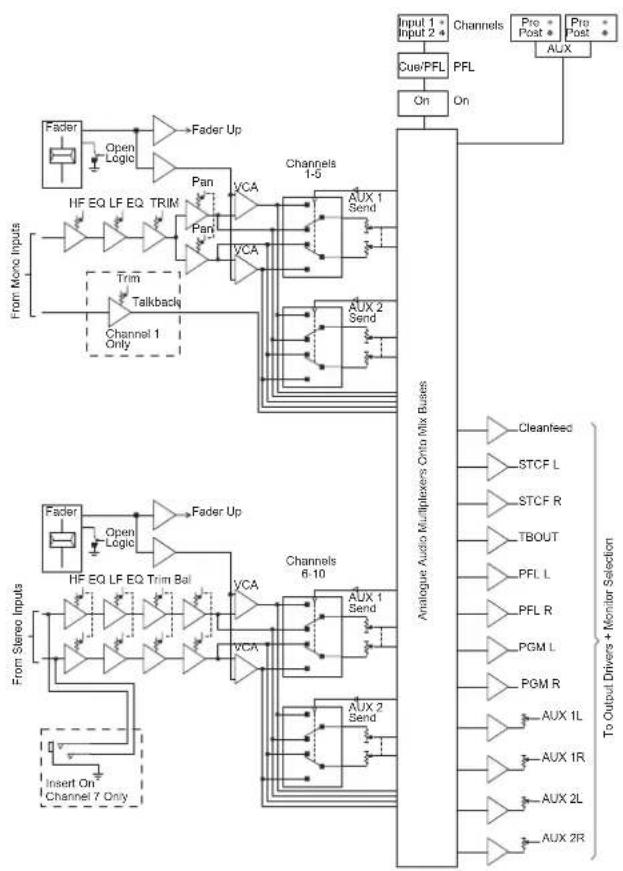
flowchart
graph TD
    A["From Mono Inputs"] --> B["Fader"]
    B --> C["Open Logic"]
    C --> D["Fader Up"]
    D --> E["HP EQ LF EQ TRIM"]
    E --> F["Pan"]
    F --> G["VCA"]
    G --> H["Channels 1-5"]
    H --> I["AUX 1 Send"]
    I --> J["Analog Audio Multiplexers Crito Mix Ruses"]
    J --> K["Cleanfeed"]
    J --> L["STCF L"]
    J --> M["STCF R"]
    J --> N["TBOUT"]
    J --> O["PFL L"]
    J --> P["PFL R"]
    J --> Q["PGM L"]
    J --> R["PGM R"]
    J --> S["AUX 1L"]
    J --> T["AUX 1R"]
    J --> U["AUX 2L"]
    J --> V["AUX 2R"]
    W["From Stereo Inputs"] --> X["Fader"]
    X --> Y["Open Logic"]
    Y --> Z["Fader Up"]
    Z --> AA["HP EQ LF EQ Trim Bal"]
    AA --> AB["VCA"]
    AB --> AC["Channels 6-10"]
    AC --> AD["AUX 1 Send"]
    AC --> AE["AUX 2 Send"]
    AE --> AF["Analog Audio Multiplexers Crito Mix Ruses"]
    AF --> AG["Cleanfeed"]
    AF --> AH["STCF L"]
    AF --> AI["STCF R"]
    AF --> AJ["TBOUT"]
    AF --> AK["PFL L"]
    AF --> AL["PFL R"]
    AF --> AM["PGM L"]
    AF --> AN["AUX 1L"]
    AF --> AO["AUX 1R"]
    AF --> AP["AUX 2L"]
    AF --> AQ["AUX 2R"]
    style A fill:#f9f,stroke:#333
    style W fill:#f9f,stroke:#333
    style W fill:#f9f,stroke:#333
Fig 2-3: Main Mix Stage
flowchart
graph TD
    A["Input Port"] --> B["Control"]
    B --> C["Monitor"]
    C --> D["LED"]
    D --> E["Output Port"]
    F["Input Port"] --> G["Control"]
    G --> H["Monitor"]
    H --> I["LED"]
    I --> J["Output Port"]
    K["Antenna Multiplexes"] --> L["Loadboxerter Motor"]
    M["Antenna Multiplexes"] --> N["Headzone Motor"]
    O["Antenna Multiplexes"] --> P["Signal Headsets"]
    Q["Antenna Multiplexes"] --> R["Signal Headsets"]
    S["Antenna Multiplexes"] --> T["Signal Headsets"]
    U["Antenna Multiplexes"] --> V["Signal Headsets"]
    W["Antenna Multiplexes"] --> X["Signal Headsets"]
    Y["Antenna Multiplexes"] --> Z["Signal Headsets"]
    AA["Antenna Multiplexes"] --> AB["Signal Headsets"]
    AC["Antenna Multiplexes"] --> AD["Signal Headsets"]
    AE["Antenna Multiplexes"] --> AF["Signal Headsets"]
    AG["Antenna Multiplexes"] --> AH["Signal Headsets"]
    AI["Antenna Multiplexes"] --> AJ["Signal Headsets"]
    AK["Antenna Multiplexes"] --> AL["Signal Headsets"]
    AM["Antenna Multiplexes"] --> AN["Signal Headsets"]
    AO["Antenna Multiplexes"] --> AP["Signal Headsets"]
    AQ["Antenna Multiplexes"] --> AR["Signal Headsets"]
    AS["Antenna Multiplexes"] --> AT["Signal Headsets"]
    AU["Antenna Multiplexes"] --> AV["Signal Headsets"]
    AW["Antenna Multiplexes"] --> AX["Signal Headsets"]
    AY["Input Port"] --> AZ["Power R"]
    BA["Input Port"] --> BB["Pump R"]
    BC["Pump R"] --> BD["Pump R"]
    BE["Pump R"] --> BF["Pump R"]
    BG["Pump R"] --> BH["Pump R"]
    BI["Pump R"] --> BJ["Pump R"]
    BK["Pump R"] --> BL["Pump R"]
    BM["Pump R"] --> BN["Pump R"]
    BO["Pump R"] --> BP["Pump R"]
    BQ["Pump R"] --> BR["Pump R"]
    BS["Pump R"] --> BT["Pump R"]
    BU["Pump R"] --> BV["Pump R"]
    BW["Pump R"] --> BX["Pump R"]
    BY["Pump R"] --> BZ["Pump R"]
    CA["Pump R"] --> CB["Pump R"]
    CC["Pump R"] --> CD["Pump R"]
    DE["Pump R"] --> DF["Pump R"]
    DG["Pump R"] --> DH["Pump R"]
    DI["Pump R"] --> DJ["Pump R"]
    DK["Pump R"] --> DL["Pump R"]
    DV["Pump R"] --> DW["Pump R"]
    DX["Pump R"] --> DXP["Pump R"]
    DBP["Pump R"] --> DBQ["Pump R"]
    DBQ --> DC["Pump R"]
    DDP["Pump R"] --> DDQ["Pump R"]
    DDQ --> DCP["Pump R"]
    DDY["Pump R"] --> DDZ["Pump R"]
    DDY --> DDX["Pump R"]
    DDY --> DDYP["Pump R"]
    DDYP --> DDZP["Pump R"]
    DDYQP["Pump R"] --> DDYQP["Pump R"]
    DDYQP --> DDYQD["Pump R"]
    DDYQD --> DDYQD1["Pump R"]
    DDYQD --> DDYQD2["Pump R"]
    DDYQD --> DDYQD3["Pump R"]
    DDYQD --> DDYQD4["Pump R"]
    DDYQD --> DDYQD5["Pump R"]
    DDYQD --> DDYQD6["Pump R"]
    DDYQD --> DDYQD7["Pump R"]
    DDYQD --> DDYQD8["Pump R"]
    DDYQD --> DDYQD9["Pump R"]
    DDYQD --> DDYQD10["Pump R"]
Fig 2-4: Monitors
User Guide – Section 2-2 Input Channels
S1 Input Channels
The S1 has 10 fixed format channels with two selectable inputs on each channel:
• 2 x Mono XLR Mic / Mono XLR Line Inputs
• 2 x 1 Stereo Jack Line Input
• 1 x Mono XLR Mic / Mono XLR Telco Input
• 1 x Stereo XLR Line / Stereo XLR Cleanfeed Input
• 2 x Stereo XLR Line / Stereo RCA Inputs
• 2 x Stereo XLR Line / Stereo SPDIF & Toslink Digital Inputs
Each balanced line channel has the option of a coarse 10dB boost and each microphone channel has the option of 48V phantom power. Both of these options are activated by pressing a small push button close to the inputs on the rear connectors. These buttons are recessed so that they can not be set
accidentally. You will need a small screwdriver or something similar to push these in or out.
Channels 1 and 2 Mic / Line Inputs
The Mic/Line Input channel is a mono input with a button switch to select either Mic or Mono Line. Channel 1 is used for the presenter's mic and is the source for talkback. The Talkback source can be set to come from either the Mic or the Line source irrespective of the channel input selection.
Channels 3 and 4 - Mic / Mono Line / Stereo Line Inputs The Mic/Mono Line/Stereo line Input channel is a stereo input channel with a button switch to select either Mic, Mono Line or Stereo Line. The stereo line is fed through a jack connector which is found in the centre of the XLR line connectors.
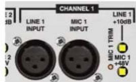
Fig 2-5: Channels 1 and 2 Mic / Line Inputs
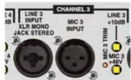
Fig 2-6: Channels 3 and 4 - Mic / Mono Line / Stereo Line Inputs
Channel 5 - Mic / Telco Input The telco channel is used to interface the S1 with a telephone hybrid unit. The hybrid unit is connected through an XLR with a Microphone channel provided as an alternative. The telco channel connector group also contains a cleanfeed output via XLR to return to the Hybrid.
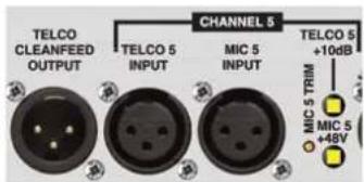
Fig 2-7: Channel 5 - Mic / Telco Input
2 User Guide
Channel 6 – Stereo Line / Stereo Cleanfeed Input
The Stereo Cleanfeed channel has one balanced stereo input and a balanced stereo cleanfeed input, on XLR connectors. The channel is intended for use where a remote stereo source, such as another studio connected via ISDN, requires a stereo cleanfeed return. The cleanfeed is generated by a separate stereo cleanfeed bus which follows the PGM output routing matrix.
Channel 7 and 8 – Stereo Line / RCA Inputs
Channels 7 & 8 have one balanced stereo input and an unbalanced RCA stereo input. Channel 7 also has DROP IN connector which allows for an input from a a 3.5mm jack connector.
Channel 9 and 10 - Stereo Line / Digital Inputs
The Digital Stereo Input channel has one standard stereo XLR Analogue Input channel & one 24-bit 192kHz digital inputs with a button switch to select between them. The digital input is auto sensing & can be connected via either SPDIF or Toslink. The digital signals are converted to analogue and from this point the channel functions are the same as the Dual Stereo Line Input channel.
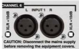
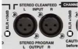
Fig 2-8: Channel 6 – Stereo Line / Stereo Cleanfeed Input
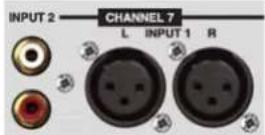
Fig 2-9: Channel 7 and 8 – Stereo Line / RCA Inputs
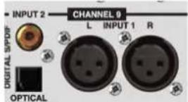
Fig 2-10: Channel 9 and 10 - Stereo Line / Digital Inputs
External Inputs
Two external inputs are available to the S1 through a 9 pin D-Type connector located on the rear panel. The external inputs are used for audio which should be heard in the control room but not on air. The pin out for this connector can be found in Appendix B.
User Guide – Section 2-3 Front Panel Channel Features
Input Selection
Selecting the button changes the channel input connection between Input 1 (Mic) and Input 2 (Line). The button is illuminated in red to indicate when input 2 is selected. When the channel is routed, so that the ON button glows green, the input selection cannot be changed.
Channels 3 and 4 have three selectable inputs; Mic, XLR Mono Line, 12 " unbalanced stereo line. The input selection button will glow red when Mono Line is selected and Orange to indicate the stereo input is selected. The button can be configured using SCi so that the button is forced to a particular input or alternatively the selection of either the Line input or the Stereo Line input can be inhibited so that the button has only two options as two line sources cannot be simultaneously connected.
DROP-IN Jack
On Channel 7 only, there is a 3.5mm insert jack allowing the direct connection of mp3 players
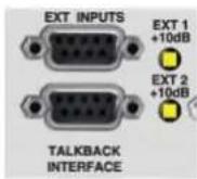
Fig 2-11: External Inputs
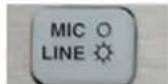
Fig 2-12: Input Selection
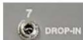
Fig 2-13: DROP-IN Jack
or other portable consumer equipment. When the INSERT jack is in use, it overrides the Input Selection Button.
AUX Controls
Each channel is sent to both auxiliary buses at all times. The AUX controls allow adjustment of the level of each channel on the bus to achieve a perfect mix. The control changes the level between fully attenuated and unity so to remove a mix from a particular auxiliary bus, fully attenuate that particular channel.
Equalisation Controls
In some situations you made need to change the equalisation of your audio. The HF and LF controls are used to adjust the equalisation of the signal. The HF control boosts and cuts the signal by ±7dB at 6.5kHz. The LF control boosts and cuts the signal by ±7dB at 100Hz. The fundamental frequency of human voice generally sits between 100 and 150 Hz. Try lowering the LF control on microphone channels to get rid of any unnecessary low frequency audio while slightly boosting the HF to add clarity.
TRIM Control
The Trim control is used to tweak the level of the channel on the PGM output. It provides an additional ±12dB of gain to fine tune the input signal level. It is a good idea to set up all your audio channels so that they are all at the same reference level when the fader is fully up, meaning the mix levels are determined solely by the position of the faders. This is where to use the trim pots, for level adjustment which remains constant through the mix.
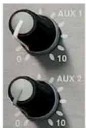
Fig 2-14: AUX Controls
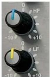
Fig 2-15: Equalisation Controls
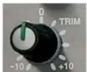
Fig 2-16: TRIM Control
PAN Control
The Pan control is used to pan the mono input signal on channels 1,2 and 5 in the stereo image. Fully anti-clockwise pans the signal to the left and increases the signal by 3dB (right channel reduces by 70dB); full clockwise pans the signal to the right and increases the signal by 3dB (left channel reduces by 70dB).
Balance Control
The balance control is used to alter the stereo image of a stereo input source on channels 3, 4, 6, 7, 8, 9 and 10. Turning the potentiometer fully anti-clockwise shifts the signal to the left and increases the signal by 6dB (right channel reduces by 6dB); fully clockwise shifts the signal to the right and increases the signal by 6dB (left channel reduces by 6dB).
CUE/PFL Selection
Selecting the CUE/PFL button routes the pre-fader input signal to the monitoring system where the signal can be heard via headphones and/or loudspeakers. The level may be checked on meters and adjusted via the TRIM control and panned via the PAN control. The button is illuminated in green when CUE/PFL is active. There is a configuration option to cancel the CUE/PFL selection when the fader is raised. This button works with both a momentary
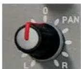
Fig 2-17: PAN Control
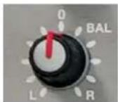
Fig 2-18: Balance Control
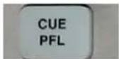
Fig 2-19: CUE/PFL Selection
2 User Guide
and latched operation. If held down, the selection is cancelled when released, otherwise the button is alternate action.
CUE/PFL & T/B Selection
On channels 5 and 6 the CUE/PFL and T/B button operates similarly to a standard CUE/PFL button except the talkback source is also routed to the respective cleanfeed output when the channel input is set to Input 2 (5. Telco or 6. Stereo Cleanfeed).
An additional option that is configurable using SCi allows the presenter to CUE/PFL the Telco or STCF inputs whilst preventing the talkback source from being routed to the cleanfeed outputs. If Talkback routing on this channel is 'disabled', the CUE/PFL & T/B button shall flash green when selected to indicate that talkback is not routed to the cleanfeed bus. Talkback can be routed to the stereo cleanfeed bus by holding the CUE/PFL & T/B button and the button will glow solid. When the button is released, talkback will return to the unrouted state & the button will return to flashing green. CUE/PFL can be deactivated by a momentary press of the button. This option only applies to Input B of this channel.
ON Selection
The ON (called LINE HOLD on channel 5) button works in conjunction with the fader. It is used to control channel remote output logic, channel routing, and timers. The button LEDs show the various operational states of the channel.
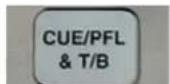
Fig 2-20: CUE/PFL & T/B Selection
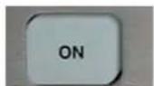
Fig 2-21: ON Selection
Unlit
When unlit the channel is off.
On solid - red
Steady red indicates that the channel is ON and "armed", ready for the fader to be raised.
On solid - green
Raising the fader changes the illumination to green indicating that the channel is live. With the button unlit the fader may be raised and the channel can be operated simply by selecting ON. The illumination in this case toggles between unlit and green. The channel remotes and timers are triggered when the fader is up and the channel ON button shows green.
Flashing red
On channels 9 and 10 when Input 2 (Digital Input) is selected, the channel ON button will flash red to indicate that the input is not locked to a valid source. The channel cannot be opened if the Digital input is not synchronised to a valid source.
The button can also flash green and flash orange. Please refer to the tally back portion of section 4 (page 23) for more information.
Scribble Pad
A scribble pad is provided at the bottom for user labelling of the channel function. This is useful to remind a producer or presenter which channels contain which segments of audio. It is advisable to use a non-permanent pen or pencil in case of changes.
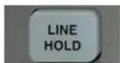
Fig 2-21B: LINE HOLD

Fig 2-22: Scribble Pad
Fader
The 100mm VCA fader provides a method of dynamic in-show level control and operates between fully attenuated in its lowest position and unity gain when fully open. The channel input signal is routed to the PGM output whenever the fader is open, and the ON button is selected. If using the auxiliary bus post fade, the fader position also affects the level of the channel on the auxiliary buses. The faders can be forced up for remote control applications using one of the General Purpose Inputs.
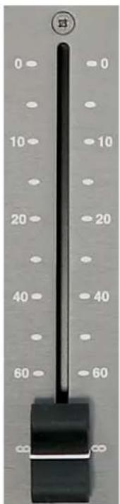
Fig 2-23: Fader
User Guide – Section 2-4 Metering and Monitors
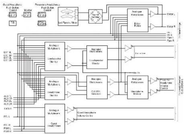
Monitor and headphone sockets The S1 provides a monitoring system to monitor all output channels or the external inputs. The is useful for setting up the mixer outputs or to simply listen to the mix in a control room. There are four jack outputs in total; two paralleled presenter outputs, one guest output and one monitor output. The source which is heard on the monitoring system is selectable via push button. The buttons are set to interlocking mode by default, which means the button pressed becomes the source, cancelling all others. An alternative mode of operation is mixing mode, which mixes the output sources onto the monitor bus instead. All the buttons can be locked out in either the off or on positions to stop accidental selection. To find out how to set up these functions further please view section 4 - SCi (page 24). The PGM, AUX1 and AUX2 buttons all illuminate in green. EXT1 and EXT2 both illuminate in red.
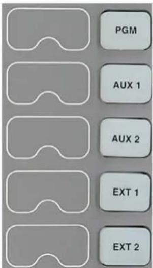
Fig 2-24: Monitor and headphone sockets
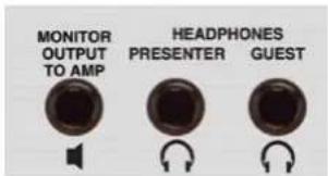
Fig 2-25: Presenter & Guest Headphones Connector
2 User Guide
Presenter & Guest Headphones Connector
This standard 6.35mm jack socket is used for the control room headphones and the guest headphones. The presenter jack is wired in parallel with the headphone connector on the front panel. Each connector is capable of driving 35 ohm impedance headphones. Please see section 3 – Applications (page 16) if you would like to use more than one set of headphones on a particular output.
Control Room Monitors Connector
This standard 6.35mm jack socket is the output for the control room monitor loudspeakers. A suitable amplifier should be used to send this signal to the loudspeakers, or connect active loudspeakers directly to this output.
Monitor and Headphone Controls
Level controls
Each monitor output has it's own level control which operates on a range of zero to ten. Zero represents fully attenuated and ten represents +6dB in the guest and presenter headphones or unity in the monitor.
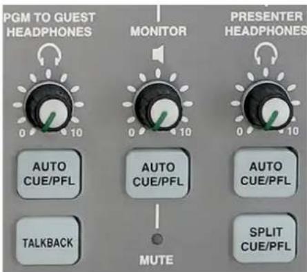
Fig 2-26: Level controls
Auto CUE/PFL
When the green illuminated AUTO CUE/PFL button is selected, any input channels selected to CUE/PFL are automatically routed to the appropriate out. The selection of this button can be locked if required.
Split CUE / PFL
The presenter headphones have the additional facility of SPLIT CUE/PFL. When this button is selected, the monitor source will be heard in mono in the left headphone, and CUE/PFL will be heard in mono in the right headphone. The button is illuminated yellow when selected. The selection of this button can be locked if required.
Talkback
When pressed, the Talkback button will route talkback from the talkback microphone to the guest headphones. The talkback signal can be configured to either cut or mix into the headphones.
While the talkback button is pressed, the switch is illuminated RED and the talkback is active. The buttons work with both a momentary and latched operation. If held down, the selection is cancelled when released, otherwise the button is alternate action.
If necessary it is also possible to permanently route the talkback audio to the talkback connector on the back panel irrespective of whether TALKBACK or CUE/PFL & T/B have been pressed. This may be required if an additional talkback routing panel is used to route talkback to multiple locations.
Mute
The red mute LED will illuminate whenever a mic channel, which has been designated to Control Room mute, goes live. This will mute the control room monitors to prevent feedback. Two pairs of contacts on the remote connector of the PGM output channel will close whenever the mute function is active. These can be used to remotely illuminate "Mic Live" lights.
Dim / Mute
When a channel with the monitor mute option configured has PFL selected, the control room monitors can be set to either dim or mute. If the fader is then opened, the monitors will mute irrespective of this setting. The red mute LED will still illuminate if the monitors are set to DIM rather than MUTE on PFL.
Meter Controls
Program / Meters Follow Monitors
The PGM / MFM Button selects whether the meters should display PGM only or display the selection that is heard in the presenters headphones. The selection of this button can be locked if required. This button is illuminated RED if MFM is selected.
Fig 2-27: Program/Meters Follow Monitors
PPM / VU
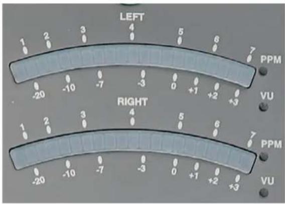
Fig 2-28: PPM / VU
The meters can be configured to display either PPM or VU. A red LED is illuminated next to the currently active scale. The meter mode is a configuration option available through SCi
The PPM meters have a 1-7 scale and will be configured such that a 1kHz signal, at 0dBu at the PGM output, will indicate a meter reading of 4. Each mark on the PPM scale indicates a 4dB change in signal level.
The VU meter operates between -20 and +3 Volume units and follows the standard definition for a VU meter. Please see ANSI C16.5-1942, BS 6840 or IEC 60268-17 for more details.
User Guide – Section 2-5 Output Buses
PGM Output
The PGM output provides stereo balanced XLR outputs. The PGM Output is used as the main transmission bus. All channels that are on and faded in are mixed on to this bus.
Cleanfeed Outputs
The Telco cleanfeed is a mono balanced output used to return a mono version of the program bus back to telephone hybrid. All channels except channel 5, input 2 (Telco) are routed to this bus.
The stereo cleanfeed output works in a similar way to the to the telco cleanfeed. Essentially, it is the same as the PGM output without channel 6, input2 routed. This can then be used as a return for an ISDN codec.
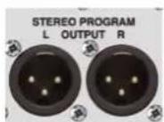
Fig 2-29: PGM Output
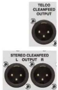
Fig 2-30: Cleanfeed Outputs
2 User Guide
Digital Outputs
The S1 has two digital outputs that work at the same time. The first is AES/EBU which is on a balanced XLR connector. The second is S/PDIF which is found on an unbalanced RCA connector. These both carry
the PGM output. The digital output can be synced to either the on-board master clock or either of the designated sync inputs. There are three distinct synchronisation modes:
Master Mode
The digital outputs are locked to the on-board master clock and is therefore constantly operating at the chosen sample rate. No sync signal is used or required. The internal clock can be set to 32, 44.1, 48, 88.2 and 96kHz.
Slave Mode
The digital outputs are locked to one of the three external sync inputs; AES/EBU, S/PDIF or word clock. If the lock is lost, the digital PGM output is disabled until another lock is secured.
Auto Mode
The digital outputs are locked to one of the three external sync inputs but if the sync is lost, the master clock replicates and resumes at the sample rate of the lost signal.
When the digital output of the mixer is set to either slave or auto modes, the desk will automatically synchronise to the first available input source. The three sync inputs, AES/EBU, S/PDIF and word clock are all auto sensing.
To learn more about the configuration of synchronisation options, read section 4 – SCi (page 24).
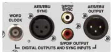
Fig 2-31: Digital Outputs
Lock Indicator
The illuminated lock indicator shows that the digital output is locked. If synchronisation is lost then the indicator will flash.
Auxiliary Outputs
The S1 has two auxiliary buses so that alternative outputs from the PGM can be created and used. The mix that is created on these buses is available from a 9 pin d-type connector which is located on the rear panel. For more information on the use of the auxiliary bus, please read section 3 – Making the most of the auxiliary outputs (page 19).

Fig 2-32: Lock Indicator
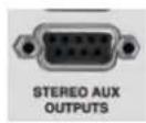
Fig 2-33: Stereo Aux Outputs
Auxiliary master gain and PRE / POST Selection
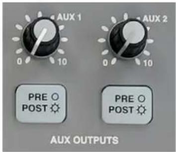
Fig 2-34: Auxiliary master gain and PRE / POST Selection
Each auxiliary bus has a master gain control. This controls the level of the whole bus between fully attenuated and unity. Each bus also has a global setting of PRE or POST fader. If PRE is selected, each channels audio is routed to the auxiliary bus before it passed through the fader. This means
that the fader has no effect. If POST is selected, the audio is routed to the auxiliary bus after it has passed through the fader. This means that the fader now plays a part in the overall level of that channel on the auxiliary bus. This is true whether the channel is turned on or not. If POST is selected, the button will be illuminated red. Both buttons can be locked in either mode. Additionally, by default, a POST auxiliary bus can not be set to PRE until all the faders are down. For more information on how to configure these options, please read section 4 – SCi (page 24).
3 Mixer Applications
3 Mixer Applications
The following section will show you how to setup and use the mixer for most standard applications. It is intended as a quick 'how to' guide to get you up and running as quickly and efficiently as possible. If you are already comfortable with setting up the mixer, please move on to the next chapter – Advanced Configuration to learn how to further configure your desk and get the most from your equipment.
Before reading this section it is recommended that you familiarise yourself with all the different types of connectors and cabling that is used on the S1. Please refer to appendix A.
The following section is divided into these parts:
• 1. Standard setup and applications. Page 16.
• 2. Making the most of Auxiliary Outputs. Page 19.
• 3. The use of external equipment with the S1. Page 20.
Presenter Controlled Studio
The following setup with a presenter in a studio controlling all aspects of the transmission is ideal where space or resources are limited. This kind of setup would suit small radio stations including university or hospital radio. The setup diagrams are divided into 3 figures for clarity.
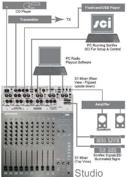
flowchart
graph TD
    A["CD Player"] --> B["Transmitter"]
    B --> C["TX"]
    D["Flashcard/USB Player"] --> E["PCI"]
    E --> F["PC Running Sonifex SCI For Setup & Control"]
    G["PC Radio Playout Software"] --> H["S1 Mixer (Rear View - Flipped upside down)"]
    I["Amplifier"] --> J["Speakers"]
    K["S1 Mixer (Top View)"] --> L["SONIFEX SignalLED Illuminated Signs"]
    M["Studio"] --> N["Speaker"]
Fig 3-1a: Presenter In Studio - External Equipment Connections
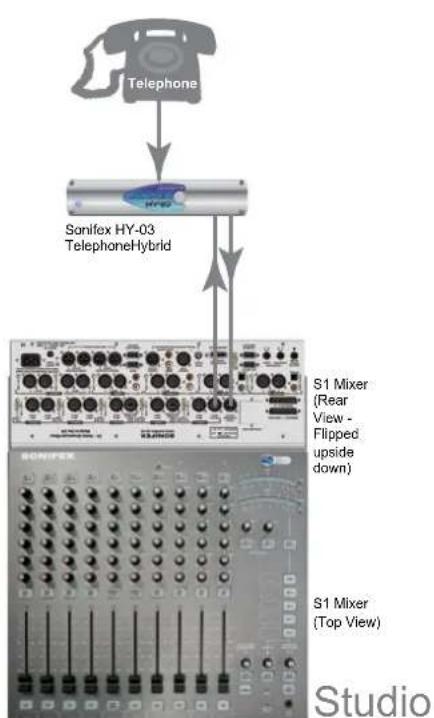
flowchart
graph TD
    A["Telephone"] --> B["Sonifex HY-03 Telephone Hybrid"]
    B --> C["S1 Mixer (Rear View - Flipped upside down)"]
    B --> D["S1 Mixer (Top View)"]
Fig 3-1b: Presenter In Studio - Telephone Line Connections
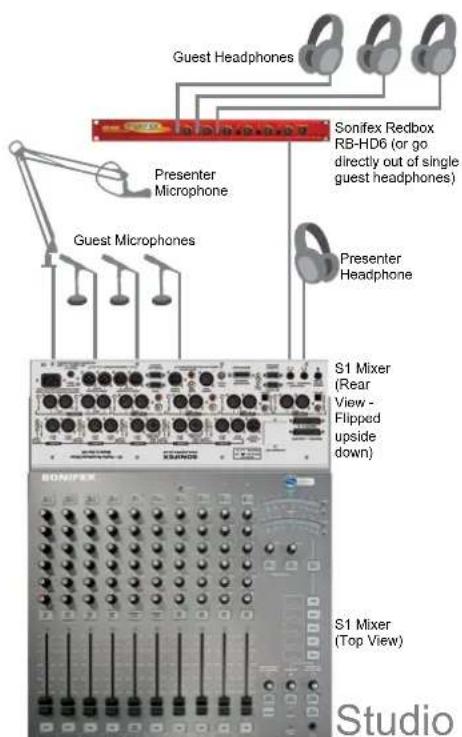
Fig 3-1c: Presenter In Studio - Presenter and Guest Connections
3 Mixer Applications
Producer Controlled Studio With Separate Presenter
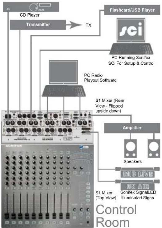
Setting up the mixer in this way allows the presenter to present and hands the production responsibility to someone else. This kind of setup would be ideal in situations where the presenter is unskilled with mixing desks
flowchart
graph TD
    A["CD Player"] --> B["Transmitter"]
    B --> C["TX"]
    D["Flashcard/USB Player"] --> E["PCI"]
    E --> F["PC Running Sonifex SCI For Setup & Control"]
    G["PC Radio Playout Software"] --> H["S1 Mixer (Rear View - Flipped upside down)"]
    I["Amplifier"] --> J["Speakers"]
    J --> K["MIC LIVE"]
    K --> L["ON AIR"]
    L --> M["S1 Mixer (Top View)"]
    M --> N["Sonifex SignalLED Illuminated Signs"]
    style A fill:#f9f,stroke:#333
    style D fill:#f9f,stroke:#333
    style I fill:#f9f,stroke:#333
    style K fill:#ccf,stroke:#333
    style L fill:#ccf,stroke:#333
    style M fill:#ccf,stroke:#333
Fig 3-2a: Presenter And Producer In Control Room - External Equipment Connections
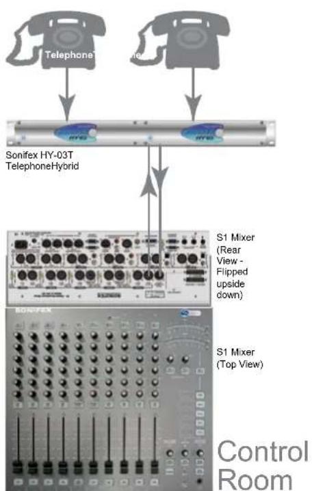
allowing an engineer to control the audio quality, while the presenter concentrates on the audio content. Another case for this method is if the presenter and guests are being filmed. The equipment can be discretely in another room, rather than cluttering the video. Again, the setup diagram is split into 3 figures for clarity.
flowchart
graph TD
    A["Telephone"] --> B["Sonifex HY-03T Telephone Hybrid"]
    C["Phone"] --> B
    B --> D["S1 Mixer (Rear View - Flipped upside down)"]
    B --> E["S1 Mixer (Top View)"]
    D --> F["Control Room"]
    E --> F
Fig 3-2b: Presenter And Producer In Control Room - Telephone Line Connections
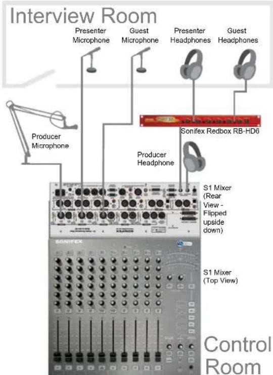
Fig 3-2c: Presenter And Producer In Control Room - Presenter and Guest Connections
Global Talkback
The Global Talkback Mode provides a method of guests talking to each other when all of their faders are down. The Global Talkback Mode, automatically activates the CUE/PFL button on the respective channels as well as turning on AUTO CUE/PFL on the Guest Headphones allowing the guests to hear and talk to each other. The presenter can cancel any of the channel CUE/PFL's at any time. When a channel fader in the global talkback group goes up, the global talkback mode deactivates and the CUE/PFL and AUTO CUE/PFL buttons return to their original state. To Configure a Global Talkback please refer to the SCi chapter of the handbook.
User Guide – Section 2-3 Making the most of auxiliary outputs
The auxiliary buses provide two alternative outputs to use as desired. This opens up several practical options to the user.
Auxiliary bus to record a session
The user can connect the either auxiliary output to recording equipment and record what is present on the bus. The producer decides what audio is on the bus by setting the volume on each channel to the appropriate level, creating a totally new mix. Using PRE and POST allows the producer to discriminate between recording all audio or just what is faded in at the time. The producer can also decide what output level the mix should have by using the master volume control for the particular AUX channel in use.
Auxiliary bus to record an off air phone call
It is possible to use an auxiliary bus to record a telephone conversation off air, whilst transmitting from the PGM output. Before the conversation, chose an auxiliary bus and turn down all of the individual channel gains. Turn the gain on the presenters channel (typically channel 1) and the telco channel (typically channel 5) to the required levels and set the bus to PRE. When the phone call is received, the presenter can press the CUE/PFL & T/B button and talk to the caller. The conversation can be recorded using
3 Mixer Applications
external equipment connected to the specific auxiliary output on the back panel.
Log the presenter
The user can create content review material by logging all presenter dialogue. Chose an auxiliary channel and turn down all individual channel gains for that channel. Turn the presenters auxiliary channel gain to the required level, set the master gain and use in POST mode. All on air material from the the presenters mic can be recorded from the auxiliary output on the back panel.
To avoid the patches of silence that would occur while audio or jingles are playing, use the remote control start and stop signals that are used to trigger the CD player, jingle player etc to also trigger the logging equipment if this option is available. Find out more about the remote control ports in chapter 4.
Create a talkback source
If you require multiple talkback sources, create a custom talkback mix on an aux channel and set is to PRE. Connect the Aux Output L to the channel 1 LINE input. After connecting the presenters Mic to channel 1, Use SCi (to find out more about SCI, turn to section 4) to configure the talkback source to channel 1 Line and lock the channel 1 source button to Mic Input. This will prevent a loop back connection.
Use an auxiliary bus to create a clean feed for a hybrid unit If the user would like to use a second hybrid, an auxiliary channel can be used to create a clean feed return. Turn the gain to all channels that are being broadcast to the required levels except for the channel which is receiving the audio from the second hybrid. Select POST so that everything that is heard has been mixed correctly. This channel should be muted. Connect the left channel of the auxiliary output to the the second hybrids clean feed input. If presenter would like to talk to the caller off air, turn off the presenter channel and fade in. This will allow the the presenter to be heard on the auxiliary bus but not on the PGM output. The presenter can press CUE PFL on the second hybrid channel to listen to the caller.
User Guide – Section 3-4 External equipment and the S1
Most of the equipment needed such as microphones, headphones and CD players are self-explanatory. Occasionally you may need extra external equipment to really make the most of the mixer. Here are a few suggestions:
Headphone distribution amplifiers
If the application requires more than one set of guest headphones, then a headphone distribution amplifier is required. This will take one headphone output and create multiple new outputs from it, without affecting the signal or line impedance. Simply take the output from the guest headphones socket and connect it to the distribution amplifier. It is recommended that you use the SONIFEX RB-HD series.
Microphone amplifiers
Some applications may require more microphone inputs. If this is the case you could use the Line inputs with dedicated microphone amplifier. Connect your microphone to the amplifier's input and connect the amplifier's output to the required line input. It is recommended that you use the SONIFEX RB-MA series.
Telephone hybrid
Use a telephone hybrid to open the show up to interaction with the outside world. A hybrid allows you to receive phone calls and send them to your mixer as audio. Connect the hybrids audio output to the mixers telco channel (channel 5) and connect the channel's clean feed output to the line input on the hybrid. The mixer has been designed to work with the Sonifex HY-03.
On-Air Light
S1 rear panel 9 way
D-Type Talkback connector
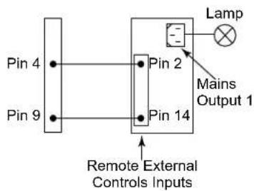
Fig 3-3: On-Air Light
The On-Air light, also known as Mic Live, is used to indicate to everyone inside or outside of the Control Room and/or Studio that microphones are live and on-air. A set of latching relay contacts, activated by a control room mute, are available on the Talkback 9 way D type socket on the rear panel of the mixer for the Control Room On-Air light. See the pin-outs of the talkback interface for details. Shown below is an example of connecting the latching relay contacts on the talkback interface to a SONIFEX RB-LC3. The remote connection on the RB-LC3 is active low.
Mic Cue Light
The mic cue light is used to indicate to a guest, etc, situated in a talks studio, that they should speak. The cue light is usually green, and there is usually one per microphone. This should not be confused with a mic live light, which is red and there is one per studio or control room, also known as "On Air light" (see above).
Open collector outputs for each channel are provided on the Remote Connectors. See the remote connectors section for details
NOTE: It is vital that mains voltages are NOT connected to any of the connectors on the mixer. If your On-Air light is to be mains operated then you should use a suitable opto-isolated solid-state mains relay. The SONIFEX RB-LC3 Light/Power controller is a suitable unit that will control up to three On-Air lights and/or Mic cue lights.
Voice Processors On Mic Channels
To use an outboard effects unit with a microphone, for example, a voice processor an auxiliary bus could be used and returned through a spare input channel.
Use of the external inputs
The external inputs found on the rear panel are used to send audio to the presenter and guest headphones and to the monitor output. The external inputs can not be routed to the PGM output. Theses should be used to relay information information or audio to the presenter and guests which should be kept isolated from the transmission path.
Connect portable audio sources using DROP-IN
The drop in socket is used to add audio from an additional external source such as a portable MP3 player. Connect the source to the mixer and the source will over ride all audio on Channel 7. This can be routed to the PGM output.
Meterbridge
The meterbridge is an expansion port that allows external meterbridge components to be connected. This includes a variety of different meter, timer and monitor panels. The meterbridge port can also supply up to 15V @ 200mA to external equipment if required. Appendix A (page 31) contains the pin out and pin description for this port. For more information on meterbridge components, please contact Sonifex.
4 Advanced Configurations
4 Advanced Configurations
The following section will show you how to truly maximise the mixers potential. Learn how to control and trigger external equipment from your mixer, send visual messages to the presenter enable off air group discussions and much more.
The following section is divided into these parts:
- Remote Control – Control external equipment with fully configurable remote control functions.
- General purpose inputs and outputs – Use a single or multiple combination of mixer events to control external function. Page 23.
- SCI control interface – Learn how to configure your mixer using the dedicated software interface, page 24.
User Guide – Section 4-1 Using the Remote Control
The remote control ports are available so that the user can control external equipment from the mixer. The two remote connectors on the rear panel contain all of the START & STOP outputs from the input channels. Each channel input has its own START and STOP remote controls except the microphone inputs which only have START outputs. In the eventuality that you require a microphone stop control signal, this could be configured using one of the general purpose outputs.
Remote Mode
The remotes can be configured in a variety of different ways:
- Remotes Disabled
- The remotes are not used and are not controlled by the desk
- If the stop control is set to continuous, then the stop signal will always be on
- If the stop control is set to pulsed, then the stop signal will always be off
- Start from ON & Fader Up
- The start signal is generated when the channel is live (when the ON button is solid green)
- A stop signal is generated when the channel is not live
- Telco Mode
- The Telco mode sends the start pulse when the channel is initially armed (ON button glows RED) This allows a hybrid to connect before the channel goes live.
- n this mode the stop signal is generated when the ON button is turned off (not glowing)
- Start from CUE/PFL & ON
- As well as the start signals being generated when the channel is live, a start pulse can be configured to be sent when the CUE/PFL button is pressed. This option would allow the automatic start of a CD player for example, when the presenter prefades that particular channel.
- Telco Mode with CUE/PFL
- This operates the same as the telco mode except the CUE/PFL button can also generate start and stop remote signals
Momentary/Continuous
- Each remote output can be configured to operate in momentary or continuous modes.
Repeated Starts Mode
It is possible to configure the ON button to operate in a Repeated Start Mode. If this option is enabled, a start pulse will be sent when the channel initially goes live. If whilst the channel is live (ON button is green), the ON button is pressed again, an additional start pulse will be sent.
User Guide – Section 4-2 General purpose inputs and outputs
The S1 has five General Purpose Inputs/Outputs (GPIO) available. Each GPIO has been designed to be very versatile & almost any operation with the mixer can be achieved when utilising them.
General Purpose Inputs
Each GPI can be configured to perform up to 10 different operations from a single input. For example, in a remote play out situation, you may want to:
• Force 4 channels ON with the faders forced up
• Force 4 channels to input 1
- Mute the Control Room Monitors
This configuration would utilise 9 of the 10 operations available for an individual GPI.
Options / Configuration
The Input can be configured to operate in several different ways:
• Momentary / Continuous GPI
• Active High / Low GPI
To Configure a GPIO please refer to the GPI: mode in the Serial Command Interface Section.
General Purpose Outputs
Each GPO can be configured to generate an output from up to 10 different internal controls. For example, a GPO could be configured to generate a global talkback function. The GPO would be setup so that:
- When microphones 2, 3 and 4 are all not live, generate a GPO continuous output
The GPO could then be linked back into one of the GPI's with the Input Configured to:
• Force PFL on Mics 2,3 & 4
- Enable Auto CUE/PFL Guest
This would allow the guests to freely talk to each other until one of their mics goes live.
Options / Configuration
The Output can be configured to operate in several different ways as well:
• Momentary / Continuous GPO
• Active High / Low GPO
Tally Back
In addition to the telco remote mode, the channel can be configured to show the state of the external equipment. Once the channel has been armed, the channel will flash green, until a GPI signal (tally back) has been received back to confirm that the external equipment is now online. This will then allow the channel to be opened. If the external tally is lost (ie a TBU goes offline), the mixer will wait for 1 second before muting the channel & returning to the green flashing state.
In telco mode, it is possible to use the telco mode to set up an external link and then switch over to use the other input on that particular channel. If the tally is lost whilst still monitoring the other side of the input channel, the on button shall flash orange at a 25% duty cycle, to show that the external link has been lost.
To re-setup the link, the user must switch to the channel with the telco mode, turn the channel off, & then turn it back on. When the tally is received from the external equipment, the orange/green flashing will stop.
Automation Tally
An automation tally can be used as a visual indication to the presenter that something is happening or about to happen. When an auto tally is configured on a playout system channel for example, the auto tally could be used to indicate to the presenter that the playout track is about to end.
4 Advanced Configurations
When the GPI becomes active the ON button will flash green.
To configure all GPIO and tally modes, please refer to the SCi section
User Guide – Section 4-3 SCi and the S1
Sonifex SCI software is free of charge software available to control and configure the S1 Mixer, as well as a plethora of other Sonifex products, using RS-232 connections. The S1 Mixer is supported in version 1.110 and above.
Download the latest SCi Software This is located on the Sonifex website in the Sonifex Downloads section: http://www.sonifex.co.uk/technical/software
Download and install the software.
Connecting the RS-232 Serial Port: Simply connect the S1 Mixer to your computer using a serial cable, or USB to RS-232 adapter, to be ready for operation.
Using SCi for the first time:
Once the S1 Mixer is connected to the computer, launch SCi. The first thing to appear will be the SCi Launcher.
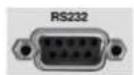
Fig 4-1: RS-232 Serial Port
![Launcher S1 Mixer S1-MIXER [0001234]](/content/2026/05/904925/images/92dc8569787294af58c6eefdc0d85473973bbebe41af9f4e993b6026439ec19f.jpg)
Fig 4-2: SCi Launcher
Click on the large plus button and the software will try and communicate with the relevant serial ports to discover any Sonifex products connected. The S1 Mixer will be shown in the list. If they are not listed, check the cable between the S1 Mixer and the computer. Close the device list and the S1 Mixer should now be in the launcher.
Double click the S1 Mixer to launch the S1 SCi interface.
SCi for S1
SCi allows the user control and configure the S1 Mixer remotely via RS-232. When using SCi for the S1 Mixer, it should not be run with a display resolution less than 1024x768. 1280x1024 is recommended.
The user interface consists of the main screen showing the status of the mixing desk and configuration screens for individual channels, system settings and GPIO.
Main Screen
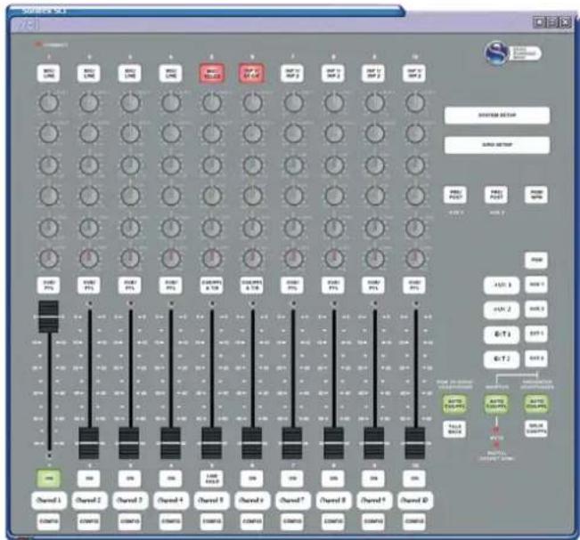
Fig 4-3: Main Screen
The main screen is designed to emulate the user controls and displays on the physical mixing console. It displays the live status of the buttons, faders, digital synchronisation and control room monitor mute.
In addition, the main screen also has an indicator for the RS-232 connection. When red the desk is connected, when yellow the desk is connecting and when white it is disconnected.
Button states can be modified by clicking on the button whereupon a menu will appear with the relevant options for the button. Through the menu it is possible to turn buttons on or off and also lock them to their current state.
The following buttons also have additional options:
- Input Select:
Set input to A or B (or C for channels 3 & 4)
Disable Mono or Stereo input (channels 3 & 4 only)
• CUE/PFL:
Turn button off when the fader is up Enable Talkback (channels 5 & 6 only)
- AUX:
Lock button when it is set to POST and a fader is up
- Monitor Select:
Interlock or mix with other monitor inputs
Note: The guest talkback button cannot be locked
The faders can also be set to "Forced Up" through the menu or by dragging the fader with the mouse cursor (if Button Control is enabled)
Buttons can be controlled with a single click by enabling "Button Control" in the menu described at the end of this chapter. In this instance the button menu can still be accessed by right-clicking on the button.
Each channel has the ability to have an alias set and displayed in the virtual scribble pad. This is set in the Channel Configuration screens. The monitor inputs (excluding PGM) also have this capability. This is set in the System Configuration screen.
Channel Configuration
Each channel can be configured and tailored to your requirements through the Channel Configuration screen. This is accessed via the "CONFIG" button bellow the virtual scribble pad for each channel.
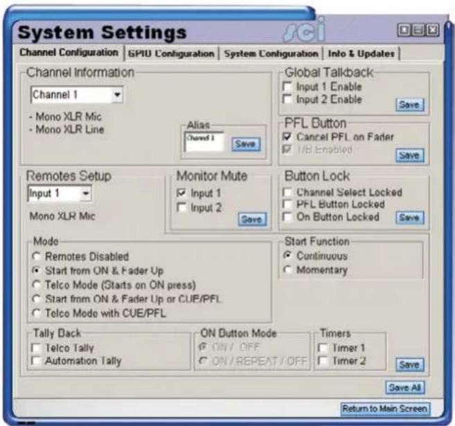
Fig 4-4: Channel Configuration Screen
4 Advanced Configurations
Channel Information Box:
This displays the input options of the channel and allows you to change the alias text on the main screen. To select another channel, use the drop down box.
Global Talkback Box:
This allows you to enable or disable Global Talkback mode for a particular input on the channel. See page 19 for more information on global talkback.
PFL Button Box
Cancel PFL on Fader:
When enabled, the PFL for the channel is turned off when the channel becomes routed (On & fader up)
T/B Enabled (channels 5 & 6 only):
When disabled, the PFL is not routed to the talkback interface unless the CUE/PFL & TB button is held down. If the CUE/PFL & TB button is on (routing to PFL), it will flash to indicate this and solid to indicate it is being routed to the talkback interface.
Button Lock Box:
Locks the buttons on the desk in their current state. For channels 3 & 4 it is possible to restrict the operator to Mic & Mono Line inputs or Mic & Stereo Line inputs.
Monitor Mute Box
This allows you to configure which inputs have the ability to mute the control room monitor output when the channel is routed to the program output.
Remotes Setup Box
Remote input/output options are configured for inputs 1 & 2 independently. The current input displayed can be changed using the drop down box.
Mode:
This allows you to set the conditions for the remote output to be active
- Remotes Disabled – Remote outputs are never started or stopped.
- Start from ON & Fader Up – Started when the ON button is active and the fader is up. Stopped when the fader is down or the ON button is deactivated.
- Telco Mode (Starts on ON press) – Started when the ON button is activated. Stopped when the ON button is deactivated.
- Start from ON & Fader Up or CUE/PFL – As per Start from ON & Fader Up but with the addition of being started when the CUE/PFL button is activated and stopped when it is deactivated.
- Telco Mode with CUE/PFL – As per Telco Mode but with the addition of being started when the CUE/PFL button is activated and stopped when it is deactivated.
Start Function:
This sets whether the Start function is continuous (remains active) or momentary (active for a approximately half a second)
Stop Function:
This sets whether the Stop function is continuous (remains active) or momentary (active for a approximately half a second). Please note, microphone inputs on channels 1-5 have no stop function.
Tally Back
Telco Tally: Enable/ disable the Telco Tally Back input. If enabled, a GPI must be configured to perform this task and the Remote Mode must be set to a Telco Mode
Automation Tally: Enable/ disable the Automation Tally Back input. If enabled a GPI must be configured to perform this task.
ON Button Mode
This allows you to select how the ON button affects the remote signal
- ON/OFF: the remote starts when the button is turned on and stops when the button is turned off
- ON/REPEAT/OFF: as per ON/OFF with an additional start signal being triggered when the ON button is pressed again without being turned off i.e. when the channel is routed.
Timers
This allows you to configure which inputs will trigger a timer signal when the channel becomes routed. This is used with an external timer device such as the Sonifex S2-MT Meterbridge Timer Panel.
GPIO Configuration
The GPIO screen allows the configuration of up to 10 functions for each GPI/GPO and also options for the functions. Lists of common functions and options are provided by Sonifex within SCI. For bespoke functions and options please contact Sonifex.
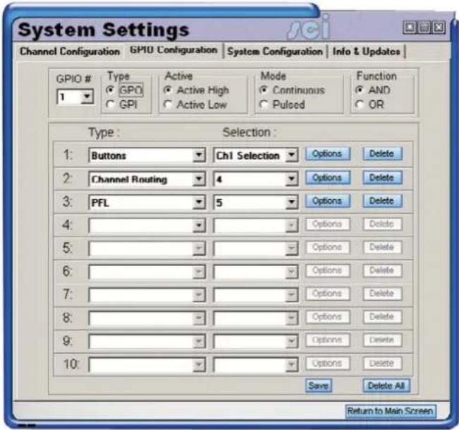
Fig 4-5: GPIO Configuration Screen
4 Advanced Configurations
System configuration
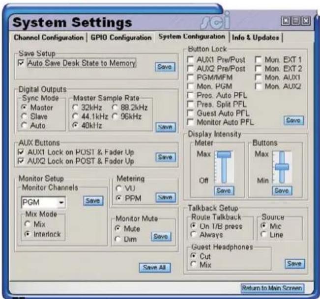
Fig 4-6: System Configuration Screen
Save Setup Box
This configures the internal memory of the S1
Auto Save Desk State to Memory:
This enables or disables the desk state tracking function within the S1. When enabled, the state of the desk including buttons is saved every 10 seconds, unless a button is pressed within those 10 seconds. This enables the desk to restore the state should the desk lose power.
Digital Outputs Box
Here the Synchronisation Mode and the internal sample rate is set.
Sync Mode:
• Master: the output is always the sample rate specified by the Master Sample Rate
- Slave: the output always follows the sample rate of the Sync Input. When no Sync signal is present, the digital output is disabled.
- Auto: The output follows the sample rate of the sync input. When no sync input is present, the sample rate falls back to the Master sample rate.
Master Sample Rate
This is only available when in Master Mode. this allows you to set the sample rate used in Master or when in Auto mode and the sync signal is not present.
AUX Buttons Box
Lock on POST & Fader Up. When enabled, the AUX button is locked if it is set to post and any of the channels are currently routed.
Monitor Set-up
Monitor Channels:
Interlock/ Mix
Select whether the monitor channel will interlock or mix with other monitor channels. When set to interlock, the selection of the channel will deselect another channel also set to interlock. When set to mix, the channel will mix with other monitor channels, including any set to interlock.
Alias
Set the text displayed in the virtual scribble pad on the main screen. Note: this feature is not available for the PGM monitor channel.
Monitor Mute
It is possible to dim the volume of, instead of muting, the Control Room monitor output when Control Room mute has been activated by an input channel
Metering:
Set the meter display method to either Peak Programme Meter (PPM) or Volume Unit (VU)
Button Lock:
Set which buttons, that do not form part of an input channel, are to be locked in their current state.
Display Intensity
It is possible to adjust the brightness of the meter display and the buttons on the mixing desk. Predetermined levels of intensity for the Meters and Buttons are independently selected using the appropriate slide bar. The very top selects maximum intensity and the very bottom selects the lowest intensity. For the meters the lowest intensity is off, this is useful when using an external meter display such as the Sonifex S2-MPPT True PPM Meter Panel.
Talkback Setup Box
Route Talkback
It is possible to configure when talkback audio should be routed to the rear talkback connector output. This can either be permanent or only when the guest talkback button, channel 5 CUE/PFL & TB button or channel 6 CUE/PFL & TB button is on.
Source
The talkback source is always channel 1 but the input that acts as the talkback can be set to either Mic (Default) or Line. This is useful when using a line level input i.e. an external microphone amplifier or voice processing unit.
Guest Headphones:
When the Guest talkback button is pressed, select whether the talkback audio mixes with the current guest monitor output or replaces the output.
Information & Updates
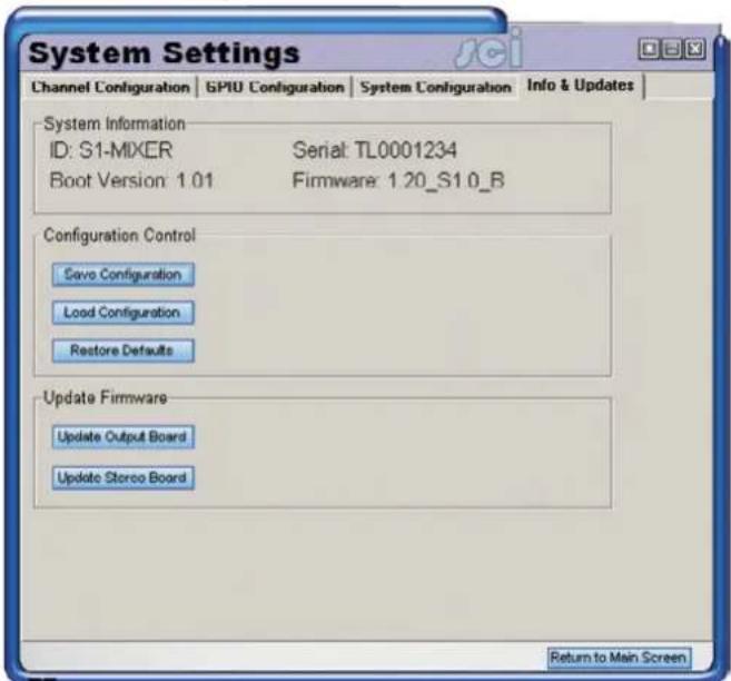
Fig 4-7: Information & Updates Screen
System Information
The system information section displays the mixer identification, serial number, base code version and firmware version. The firmware version shows 2 strings indicating the version of the output board code followed by the stereo board code.
4 Advanced Configurations
Save/ Load Configuration:
SCi provides the ability to configure the desk and store the configuration for later use. For example, a presenter may have a specific set-up for their show, whilst the preceding presenter may have their own desired set-up. Using this function, any number of configurations and be saved and recalled with a few clicks.
First, configure the desk as desired. Secondly, click "Save Configuration" and save. To reload the settings, click "Load Configuration" and select your configuration file.
Restore defaults:
This restores the S1 to factory defaults. Refer to the rest of the manual for information.
Update Firmware:
Occasionally, it may be necessary to upgrade the firmware on the S1 to add new functionality and fix software bugs. New firmware updates will be made available from time to time on the Sonifex website. Visit www.sonifex.co.uk for details. To install new firmware, click "Update Firmware", select the DWN file and click Open.
It is vital that neither the serial connection nor mains power to the S1 should be interrupted during the update process. If this should happen or the update is unsuccessful for any other reason, the S1 will enter a bootstrap mode. Another attempt at uploading the firmware can be made from here.
There are 2 processors running firmware that can be updated: the output board and the stereo board. Please ensure that you select the correct option and the correct file when updating the S1 mixer code.
RS-232 indicators
At the bottom of each screen, a red indicator will show when data is being received from the S1 Mixer and a green indicator will show when data is being sent from SCI.
Options menu
At the top of each screen, the down arrow icon will display a menu when clicked.
Debug:
This displays the data that is being transferred between SCI and the S1 mixer. It is also possible to enter RS-232 commands manually in this screen.
Launcher:
Displays the SCi Launcher
Connect/ Disconnect:
Enable/ Disable the RS-232 connection to the S1.
Properties:
Modify the RS-232 settings including Parity, Data Bits, Stop Bits and Baud Rate. Only the following baud rates are available for use with the S1:9600, 19200, 38400, 57600, 115200. The desk will automatically revert to 19200 when the desk is reset or turned on. Caution should be taken when adjusting RS-232 settings and will never normally need to be modified.
Button Control:
See the main screen section.
5 Connectors and Cabling
Many of the problems associated with installing and maintaining a mixing console are due to the use of poor cables or faulty connections. It is recommended that, wherever possible, pre-wired cables are purchased from recommended manufacturers. If you need bespoke cables making, please ensure that a qualified engineer carries out the work.
The main types of connectors used with the S1 mixers are the following:
XLR 3 Pin Connectors
The following diagram shows the pin details for the 3 pin XLR sockets and plugs:
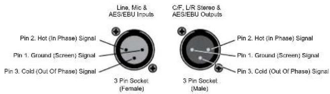
Fig 5-1: XLR 3 Pin Connectors
RCA Phono Connector
This connector is used on the Stereo RCA Channels and the S/PDIF on the digital input/output channels.
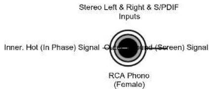
Fig 5-2: RCA Phono Connector
BNC Connector
This connector is used for the Word clock inputs on the PGM output channel.
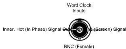
Fig 5-3: BNC Connector
6.35mm 'A' Gauge Stereo Jack Plugs
'A' Gauge Stereo Jack Plugs can be connected as follows:
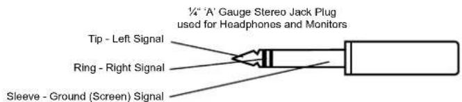
Fig 5-4: 6.35mm 'A' Gauge Stereo Jack Plugs
5 Connectors and Cabling
D Type Connectors
Several different D type connectors are used on the S1. A 25 pin plug is used for the remotes. A 9 pin socket is use for the external inputs, Auxiliary outputs, RS232, & Talkback Interface. A 15 pin socket is used for the meter bridge interface.
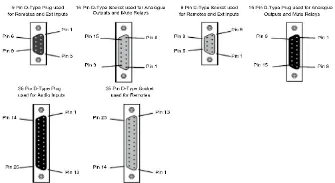
List of ports:
9 way d type socket
Fig 5-5: D Type Connectors
Connector Pin Outs
External Inputs Connector
Pin 1: Chassis ground.
Pin 2: Ext 1 left phase.
Pin 3: Ext 1 right phase.
Pin 4: Ext 2 left phase.
Pin 5: Ext 2 right phase.
Pin 6: Ext 1 left non-phase.
Pin 7: Ext 1 right non-phase.
Pin 8: Ext 2 left non-phase.
Pin 9: Ext 2 right non-phase.
Meterbridge Port
Pin 1: METER AUDIO LEFT Audio being displayed on the S1 meter
Pin 2: CUE PFL CONTROL Logic output to indicate a PFL Button is pressed
Pin 3: TIMER 2 Used to start and stop timer modules.
Can be used for timing voice-overs,
for example
Pin 4: TIMER 1
Pin 5: CUE / PFL AUDIO LEFT Audio for external metering
Pin 6: +15V 15v @ 200mA to power external
equipment
Pin 7: AGND
Pin 8: PROGRAM AUDIO LEFT Audio for external metering
Pin 9: METER AUDIO RIGHT Audio being displayed on the S1 meter
Pin 10: CONTROL ROOM MUTE
Logic signal to indicate control speakers
are muted
Pin 11: REVERSE TALKBACK AUDIO Reverse talkback to presenter
Pin 12: AGND
Pin 13: CUE PFL AUDIO RIGHT Audio for external metering
Pin 14: AGND
Pin 15: PROGRAM AUDIO RIGHT Audio for external metering
Talkback Port
Pin 1: AGND
Pin 2: TALKBACK AUDIO OUT
Pin 3: TALKBACK OUT CONTROL
Pin 4: NORMALLY OPEN RELAY CONTACT
Pin 5: NORMALLY CLOSE RELAY CONTACT
Pin 6: TALKBACK AUDIO IN
Pin 7: TALKBACK IN CONTROL
Pin 8: DGND (used for talkback control referencing)
Pin 9: WIPER RELAY CONTACT
Note: In order for the S1 talkback to be used with a S2, pin 1 and pin 8 should be connected together on the S1.
Auxiliary Output Connector
Pin 1: Chassis ground.
Pin 2: Aux 1 left phase.
Pin 3: Aux 1 right phase.
Pin 4: Aux 2 left phase.
Pin 5: Aux 2 right phase.
Pin 6: Aux 1 left non-phase.
Pin 7: Aux 1 right non-phase.
Pin 8: Aux 2 left non-phase.
Pin 9: Aux 2 right non-phase.
Mono Remote Connector
Pin 1: Channel 1 Mic Start
Pin 2: Channel 1 Line Start
Pin 3: GPIO 1
Pin 4: Channel 2 Line Stop
Pin 5: DGND
Pin 6: Channel 3 Mic Start
Pin 7: Channel 3 Line Start
Pin 8: GPIO 3
Pin 9: Channel 4 Line Stop
Pin 10: DGND
Pin 11: Channel 5 Mic Start
Pin 12: Channel 5 Telco Start
Pin 13: GPIO 5
Pin 14: Channel 1 Line Stop
Pin 15: DGND
Pin 16: Channel 2 Mic Start
Pin 17: Channel 2 Line Start
Pin 18: GPIO 2
Pin 19: Channel 3 Line Stop
Pin 20: DGND
Pin 21: Channel 4 Mic Start
Pin 22: Channel 4 Line Start
Pin 23: GPIO 4
Pin 24: Channel 5 Line Stop
Pin 25: DGND
Stereo Remote Connector
Pin 1: Channel 6 Input 1 Start
Pin 2: Channel 6 Input 2 Start
Pin 3: DGND
Pin 4: Channel 7 Input 1 Stop
Pin 5: Channel 7 Input 2 Stop
Pin 6: Channel 8 Input 1 Start
Pin 7: Channel 8 Input 2 Start
Pin 8: DGND
Pin 9: Channel 9 Input 1 Stop
Pin 10: Channel 9 Input 2 Stop
Pin 11: Channel 10 Input 1 Start
Pin 12: Channel 10 Input 2 Start
Pin 13: DGND
Pin 14: Channel 6 Input 1 Stop
5 Connectors and Cabling
Pin 15: Channel 6 Input 2 Stop
Pin 16: Channel 7 Input 1 Start
Pin 17: Channel 7 Input 2 Start
Pin 18: DGND
Pin 19: Channel 8 Input 1 Stop
Pin 20: Channel 8 Input 2 Stop
Pin 21: Channel 9 Input 1 Start
Pin 22: Channel 9 Input 2 Start
Pin 23: DGND
Pin 24: Channel 10 Input 1 Stop
Pin 25: Channel 10 Input 2 Stop
6 Technical Specification
Input / Output Impedances
Mic Input: >1k5Ω electronically balanced
Mono Line Input: > 20kΩ electronically balanced.
Stereo Line Input: >20kΩ electronically balanced.
PGM Output: < 50Ω electronically balanced
Monitor Outputs: < 75Ω unbalanced.
AES Input/Output: 110Ω
S/PDIF Input/Output: 75Ω
BNC Wordclock input: 50Ω
Input / Output Gain Range
Mic Input: Preset pot +21dB to +64dB ref -50dBu, TRIM pot ± 12dB
Mono Line Input: Switch 0dB to +10dB ref 0dBu, TRIM pot ± 12dB
Stereo Line Input: Switch 0dB to +10dB ref 0dBu, TRIM pot ± 12dB
Telco Input: Switch 0dB to +10dB ref 0dBu, TRIM pot ± 12dB
Telco Output:
Stereo Cleanfeed Input: Switch 0dB to +10dB ref 0dBu, TRIM pot ± 12dB
Stereo Cleanfeed Output:
Digital Input: 0dBFS = +18dBu on input; TRIM pot ± 12dB
Digital Output: 0dBFS = +18dBu
Frequency Response
Mic Input: 40Hz to 20kHz -1dB, +0dB
Line Inputs: 20Hz to 20kHz -0.5dB, +0dB
RCA Input: 20Hz to 20kHz -0.5dB, +0dB
Noise (20Hz to 20kHz)
Mic Input E.I.N.: -130dB with 150Ω source.
Stereo Inputs (fader down, no -92dBu ref 0dB routing):
Stereo Inputs (fader down, -91dBu one channel routed):
Stereo Inputs (unity gain, one channel routed): -86 dBu
Stereo Inputs (unity gain, two channels routed): -83 dBu
Distortion
Total Harmonic Distortion: 0.015% at 1kHz, 0dBu
0.015% at 10kHz, 0dBu
6 Technical Specification
Crosstalk
Inter-channel: > -80dBu typically
Equalisation
LF: Shelving at 100Hz. ± 7dB
HF: Shelving at 6.5kHz. ± 7dB
Range
Pan Range off/-3dB centre/off
Balance Range ± 6dB
Common Mode Rejection Ratio
Mic Input: >60dB typically
Digital I/O
Sync Input Sample Rate 32kHz – 96kHz Range:
Output Sample Rates (Using Onboard Clock): 32kHz, 44.1kHz, 48kHz, & 96kHz
Output Sample Width: 24 bit
Output
Headphone Output Load >45 ohms, recommended 400
Maximum Output (Analogue) +26dBu balanced into 2k or greater
Weight
Unit 10.5 Kg
7 Default Settings
The S1 Mixer is supplied with factory defaults set as follows. The unit can be returned to this state via SCi (see page 30) or by holding down the AUX Pre/Post and the RM/MFM buttons during power up. Hold the 3 buttons
down and 3 lamps will flash for 5 seconds and then switch fully on. Then release the buttons to return the unit to the factory default state.
| Function Options Channel 1,2,5 Channel 3,4 Channel 6-10 | ||||
| Channel SelectSee CHS: Command | Default Button Selection Input | 1 (Mic) Input 1 (Mic) Input 1 | ||
| Lockout Button Button Enabled | Button Enabled Button Enab | ed | ||
| Limit Selection - All 3 inputs selectable - | ||||
| CUE/PFLSee PFL: Command | Default Button Selection PFL | Off PFL Off PFL Off | ||
| Lockout Button Button Enabled | Button Enabled Button Enab | ed | ||
| Auto Cancel PFL Cancel PFL on Fader Up Cancel PFL on Fader Up | Up Cancel PFL on Fader Up | |||
| ONSee CON: Command | Channel armed on Input 1 | Input 1 off | Input 1 off | Input 1 off |
| Channel armed on Input 2 | Input 2 off | Input 2 off | Input 2 off | |
| Mode for Input 1 | Start / Stop | Start / Stop | Start / Stop | |
| Mode for Input 2 | Start / Stop | Start / Stop | Start / Stop | |
| Lockout Button Button Enabled | Button Enabled Button Enab | ed | ||
| Remote Input ASee RMA: Command | Mode for Input 1 | Start from ON & Fader Up | Start from ON & Fader Up | Start from ON & Fader Up |
| Start Operation for Input 1 | Continuous Start | Continuous Start | Momentary Start | |
| Stop Operation for Input 1(a GPO must be configured to use a Mic Remote Stop on channels 1-5) | Continuous Stop | Continuous Stop | Momentary Stop | |
| Input 1 Tally Back (GPI required) | Disabled | Disabled | Disabled | |
| Input 1 Auto Tally Back (GPI required) | Disabled | Disabled | Disabled | |
7 Default Settings
| Function Options Channel 1,2,5 Channel 3,4 Channel 6-10 | ||||
| Remote for Line InputSee RMB: Command | Mode for Input 2 Start from ON & Fader Up Start from ON & Fader Up Start from ON & Fader Up | |||
| Start Operation for Input 2 Momentary Start Momentary Start Momentary Start | ||||
| Stop Operation for Input 2 Momentary Stop Momentary Stop Momentary Stop | ||||
| Input 2 Tally Back (GPI required) | Disabled Disabled Disabled | |||
| Input 2 Auto Tally (GPI required) | Disabled Disabled Disabled | |||
| Control Room MuteSee MCH: Command | Enable on Input 1 Enabled Enabled Disabled | |||
| Enable on Input 2 Disabled Disabled Disabled | ||||
| TimersSee TMR: Command | Timer 1 on input 1 Disabled Disabled | Disabled | ||
| Timer 1 on input 2 Disabled Disabled | Disabled | |||
| Timer 2 on input 1 Disabled Disabled | Disabled | |||
| Timer 2 on input 2 Disabled Disabled | Disabled | |||
8 Serial Communication Protocol
Sonifex SCi remote control software handles all communication with the S1 via a convenient graphical user interface. However, this protocol is provided for those users who wish to develop their own remote control applications or communicate with the S1 using a text-based terminal program. For more information on how to install and operate the SCi software, please see page 24. Details of the protocol are available upon request. Please note that protocol for the GPI and SRQ commands are not included.
Serial Data Format
Connection is 19200,e,8,1 with XON/XOFF flow control.
Commands are case-insensitive and all parameters are in hex.
Commands should be terminated in a carriage return character, a line feed character may be sent but it will be ignored.
Responses will be CR & LF terminated.
After power up a welcome string is sent – "Initialising S1 Mixing Desk... done"
Remote Control Commands
|| indicates a shorter command can be sent. The || indicates the point at which the command can be terminated and will remain valid
On/off style options (1/0) can also be sent the value 2. This state is an ignore operation for that parameter & does not make any changes to that particular setting.
Command Description Response
ACP:a,b||c Configure Auto CUE/PFL Buttons ACK:
| A = Channel number. |
| 1 = Guest CUE/PFL |
| 2 = Monitor CUE/PFL |
| 3 = Presenter CUE/PFL |
| 4 = Reserved |
| 5 = Split CUE/PFL |
| B = Button Control |
| 1 = on |
| 0 = off |
| C = Lock Out Button |
| 1 = Lock out |
| 0 = Normal Operation |
ACP:a? Read Auto CUE / PFL Button Status ACP:a,b,c
AUX:a,b,||c,d Configure Auxiliary Buttons ACK:
A = Aux Channel number.
1 selects Ch 1
2 selects Ch 2
B = Button Control
1 = on
0 = off
C = Lock Out Button
1 = Lock out
0 = Normal Operation
D = Lock Btn if set to Post when Fader is Up
1 = Lock
0 = Normal Operation
AUX:a? Read Auxiliary Button Status AUX:a,b,c,d A = Channel number. (see above)
8 Serial Communication Protocol
| Command | Description | Response |
| Bnn: Baud Rate ACK: (at old rate) | ||
| Nn=11 (115200) | ||
| Nn=57 (57600) | ||
| Nn=38 (38400) | ||
| Nn=19 (19200) | ||
| Nn=96 (9600) | ||
BSV: Base Firmware Version BSV:x
CHS:a,b,||c Configure Channel Select Buttons ACK:
A = Channel number.
1 = Ch 1
2 = selects Ch 2
etc
a = selects Ch 10
for Channels 1,2,5-10:
B = Button Control
2 = No Change
1 = Input 2
0 = Input 1
C = Lock Out Button
2 = No Change
1 = Lock out
0 = Normal Operation
for Channels 3,4:
B = Button Control
2 = Input 3
1 = Input 2
0 = Input 1
C = Lock Out Button
4 = No Change
3 = Disable Stereo Line Input
2 = Disable Mono Line Input
1 = Lock out
0 = Normal Operation
| Command | Description | Response |
| CHS:a? | Read Channel Select Button StatusA = Channel number. (see above)N.B. On Channels 1-2 ,5-10:C will return 3 for normal operation as effectivelyit has the “stereo input” selection modedisabled. | CHS:a,b,c |
COL:a,b,c,d,e Update Intensity ACK:
A = Red
B = Green
C = Green / Orange
D = Red / Orange
E = 3MM RED LEDs
Hex Values for each colour can be in the range
0-f
| COL:? | Read Colour Values | COL:a,b,c,d,e |
| Command | Description | Response |
| 1 = ON / REPEAT / OFF | ||
| F = Lock Button | ||
| 0 = Normal Operation | ||
| 1 = Button Locked | ||
| G = Force Fader Up | ||
| 1 = Fader Forced Up | ||
| 0 = Normal Operation | ||
| N.B. if button is forced on,(F=1) the B / C = Button Control has no effect. | ||
| N.B If Telco mode on Input 1 is enabled, option D shall be forced to 0 = ON / OFF | ||
| N.B If Telco mode on Input 2 is enabled, option E shall be forced to 0 = ON / OFF | ||
| CON:a? Read ON Button Status CON:a,b,c,d,e,f,g,h,i | ||
| A = Channel number. (see above) | ||
| H = Fader Position | ||
| 0 = Fader Down | ||
| 1 = Fader Up | ||
| I = Channel Routed | ||
| 0 = Not Routed | ||
| 1 = Routed | ||
| DIM:a Configure whether a channel with control ACK:room mute selected should dim or mute monitors when it has PFL selected | ||
| A = DIM / MUTE | ||
| 1 = Dim Monitors on PFL | ||
| 0 = Mute Monitors on PFL | ||
| N.B Monitors will always mute when a channel with mute enabled goes live (ON & Fader Up) | ||
| ACK: | ||
| DIM:? Read DIM / MUTE on PFL Status DIM:a,b | ||
| B = Mute Status | ||
| 0 = Not Muting | ||
| 1 = Muting | ||
CON:a,b,c,||d,e,f,g Configure ON Buttons ACK:
A = Channel number.
1 = Ch 1
2 = selects Ch 2
etc
a = selects Ch 10
B = Input 1 ON Control
1 = on
0 = off
C = Input 2 ON Control
1 = on
0 = off
D = Mode for Input 1
0 = ON / OFF
1 = ON / REPEAT / OFF
E = Mode for Input 2
0 = ON / OFF
| Command | Description | Response |
| DIS:? | Read Digital Input Status | DIS:a,b,c,d |
| A = Channel 9 SPDIF / Optical Selection | ||
| 1 = SPDIF | ||
| 0 = Optical | ||
| B = Channel 9 Sync | ||
| 0 = No Sync | ||
| 1 = Sync | ||
| A = Channel 10 SPDIF / Optical Selection | ||
| 1 = SPDIF | ||
| 0 = Optical | ||
| B = Channel 10 Sync | ||
| 0 = No Sync | ||
| 1 = Sync | ||
| DST: | Upload Sub Processor Firmware | |
| DWN: | Upload Processor Firmware | |
| EEP:a,b Save Configuration | ACK: | |
| A = Enable write | ||
| 1 = any config updates will be written to eeprom | ||
| 0 = config updates will not be written to eeprom | ||
| B = Enable Auto Save Settings | ||
| 1 = Auto save desk state enabled | ||
| 0 = Disabled | ||
| EEP:? | Read EEPROM Status | EEP:a,b,c |
| C = EEPROM Auto Save Error | ||
| GPI:a,b | Configure GPIO | |
| A = GPIO Pin Number (1-5) | ||
| B = Data | ACK: | |
8 Serial Communication Protocol
| Command | Description | Response |
| GPI:? Read GPIO Data GPI:X,YX = GPIO Config DataY = GPI Register Control Data | ||
| GTB:a,b,c Configure Global Talkback Mode ACK:A = Channel number.1 = Ch 12 = selects Ch 2etca = selects Ch 10B = Input 1 Global Talkback Enable1 = on0 = offC = Input 2 Global Talkback Enable1 = on0 = off | ||
| GTB:a? Read Global Talkback Mode Status GTB:a,b,cA = Channel number. (see above) | ||
| MCH:a,b,c Configure Control Room Mute ACK:A = Channel number.1 = Ch 12 = selects Ch 2etca = selects Ch 10B = Input 1 Mute1 = Mute Enabled0 = Mute DisabledC = Input 2 Mute1 = Mute Enabled0 = Mute Disabled | ||
| Command | Description | Response |
| MCH:a? | Read Control Room Mute StatusA = Channel number. (see above) | MCH:a,b,c |
| MFM:a,||b | Configure Meter Follows MonitorsA = Button Control1 = on0 = offB = Lock Out Button1 = Lock out0 = Normal Operation ACK: | |
| MFM:? Read MFM Button Status | MFM:a,b | |
| MON:a,b,||c,d | Configure Monitor Selection ButtonsA = Monitor Selection number.1 selects PGM2 selects Aux13 selects Aux24 selects Ext15 selects Ext2B = Button Control1 = on0 = offC = Lock Out Button1 = Lock out0 = Normal OperationD = Interlock or Mix0 = Source will Mix1 = Source is Interlocking | ACK: |
| MON:a? | Read Monitor Selection Button StatusA = Channel number. (see above) | MON:a,b,c,d |
| MTR:a,||b Configure Meter Mode ACK:A = Meter Mode2 = No Change1= PPM0 = VUB = Intensity0 = Meter Disabled1 - 7 = Intensity Levels8 = No Change | ||
| MTR:? Read Meter Status MTR:a,b | ||
| OPM:a Configure Digital Synchronisation ACK:a = Mode0 = Internal1 = External2 = External with fallback to internal | ||
| OPM:? Read Digital Sync Mode Status OPM:a,bB = Output Sync Status0 = No Sync1 = Sync | ||
| OPS:x Configure Internal Operating Frequency of Digital OutputX = Frequency0 = 32kHz1 = 44.1kHz2 = 48kHz3 = Reserved4 = 64kHz5 = 88.2kHz6 = 96kHz | ||
| N.B. This command is only valid when Digital sync is set to InternalIf Sync is not set to Internal, Err:07 shall be returned ACK: | ||
| Command | Description | Response |
| OPS:? Read Internal SYNC Frequency OPS:xIf Sync is not set to Internal, Err:07 shall be returned | ||
| PFL:a,b,||c,d,e Configure CUE/PFL Buttons ACKA = Channel number.1 = Ch 12 = selects Ch 2etca = selects Ch 10B = Button Control1 = on0 = offC = Auto Cancel PFL on Fader Up1 = Auto Cancel on Fader Up0 = Normal OperationD = Talkback Disabled0 = Talkback Disabled1 = Normal OperationE = Lock Out Button1 = Lock out0 = Normal OperationN.B. Mode D is only available on Inputs 5 & 6.If enabled the CUE/PFL Button will on flash when Input 2 is selected. : | ||
| PFL:a? Read PFL Button Status PFL:a,b,c,d,e | ||
| RMA:a,b,c,d,e,f Configure Input 1 Remotes ACK:A = Channel number.1 = Ch 12 = selects Ch 2etca = selects Ch 10B = Start Function1 = Momentary | ACK: | |
8 Serial Communication Protocol
| Command | Description | Response |
| 0 = Continuous | ||
| C = Stop Function | ||
| 1 = Momentary | ||
| 0 = Continuous | ||
| D = Mode | ||
| 0 = Remotes Disabled | ||
| 1 = Start from ON & Fader Up | ||
| 2 = Telco Mode (Starts on On press) | ||
| 3 = Start from ON & Fader Up or CUE/PFL | ||
| 4 = Telco Mode with CUE/PFL | ||
| 5 = no change | ||
| E = Tally | ||
| 0 = Tally Back Disabled | ||
| 1 = Tally Back Enabled | ||
| F = Automation Tally (End of Track ON Button Flash Mode) | ||
| 0 = Tally Disabled | ||
| 1 = Tally Enabled | ||
| N.B. Channels 1-5 on Input 1 do not have stopremotes | ||
| The 'C' parameter must still be supplied, but will be ignored for the mic inputs 1-5A.. | ||
| If B is changed from 1 to 0, the fader may need to be cycled before the change is made | ||
| If C = 0, it will force the channel into START/STOP mode (see CON) | ||
| If D= 2, it will force the channel into START/STOP mode (see CON) | ||
| If E=1, a GPI must be configured as a tally back for this input (see GPI) | ||
| N.B. Tally cannot be enabled if the Remotes are not set to TELCO mode | ||
| If F=1, a GPI must be configured as an Automation Tally Input (see GPI) | ||
| Command | Description | Response |
| RMA:a? Read Input A Remote Configuration RMA:a,b,c,d,e,f,g,hG = Automation Tally Input StatusH = Tally Back Input Status | ||
| RMB:a,b,c,d,e,f Configure Input 2 Remotes ACK:See RMA: function for details | ||
| RMB:a? Read Input B Remote Configuration RMB:a,b,c,d,e,f,g,h | ||
| RST: Reset Mixer | ||
| SER: Unit Serial Number SER:x | ||
| SFD: Sets unit to Factory Defaults and reboots | ||
| SRQ:? Status Request SRQ:data | ||
| TAL:a,b,c,d,e Tally Control ACK:A = Channel number.1 = Ch 12 = selects Ch 2etca = selects Ch 10B = Input 1 Tally Back1 = Active Tally0 = Inactive TallyC = Input 2 Tally Back1 = Active Tally0 = Inactive TallyD = Input 1 Auto Tally1 = Active Tally0 = Inactive TallyE = Input 2 Auto Tally1 = Active Tally0 = Inactive Tally | ||
| TAL:a? Read Tally Input Status TAL:a,b,c,d,e;A = Channel number. (see above) | ||
| TBK:a,||b,c,d | Configure Talkback ACK: | |
| A = Button Control | ||
| 1 = on | ||
| 0 = off | ||
| B = Mix / Cut into Guest Headphones | ||
| 1 = Cut | ||
| 0 = Mix | ||
| C = Talkback Source | ||
| 1 = Channel 1 Line | ||
| 0 = Channel 1 Mic | ||
| D = Talkback Permanently Routed to Talkback Connector | ||
| 1 = Always Routed | ||
| 0 = Only routed when a T/B button is pressed | ||
| TBK:? Read Talkback Status TBK:a,b,c,d | ||
| TMR:a,b,c,d,e | Configure Timers ACK: | |
| A = Channel number. | ||
| 1 = Ch 1 | ||
| 2 = selects Ch 2 etc | ||
| a = selects Ch 10 | ||
| B = Timer 1 on Input 1 | ||
| 1 = Enabled | ||
| 0 = Disabled | ||
| C = Timer 2 on Input 1 | ||
| 1 = Enabled | ||
| 0 = Disabled | ||
| B = Timer 1 on Input 2 | ||
| 1 = Enabled | ||
| 0 = Disabled | ||
| C = Timer 2 on Input 2 | ||
| 1 = Enabled | ||
| 0 = Disabled | ||
| Command | Description | Response |
| TMR:a? Read Channel Timer Settings TMR:a,b,c,d,e | ||
| UID: | Unit Identification | UID:S1-MIXER |
| UPD: | Update EEPROM with current configurationIf an Err:08 is received, then the command Please Wait...cannot save the current configuration ACK:because write is disabled.Write can be enabled by sending:EEP:1,2 | |
| VER: | Firmware Version | VER:x.xx-Sy.y |
| Where x.xx is Output board firmware versionand Sy.y is the Stereo board firmware version | ||
Error Messages
| Err:01 | Command Not Found |
| Err:02 | Missing Parameter |
| Err:04 | Parameter out of Range |
| Err:06 | Serial Number Write Error |
| Err:07 | Command Not Valid in current mode |
| Err:08 | EEPROM write is disabled |
| Err:09 | TWI / Checksum Error |
9 Glossary
9 Glossary
Attenuation The reduction of a signal level. Attenuation is usually measured in dB.
AES Audio Engineering Society.
AES/EBU Professional digital audio standard covering frame format, connections and interfaces. Interface is usually on XLR sockets and plugs.
Balance The relative levels of the left and right channels of a stereo signal.
Cleanfeed A cleanfeed is the signal produced by the telco module, which is used as the output to be fed back to a caller on a telephone line. A true cleanfeed is the sum of all the other signals, which constitute the programme output, except for the caller's audio.
Clipping The onset of severe distortion in the signal path, usually caused by the peak signal voltage being limited by the circuit's headroom.
Common Mode Rejection Ratio This is the ratio of the extent to which a differential amplifier will cancel noise, which is present on both inputs, compared to its ability to amplify the wanted signal.
Cross-talk This is the amount of an unwanted signal which appears, or is induced, on a different or unassimilated signal. The problem is usually most prevalent with adjacent channels.
CUE - See PFL.
dB (decibel) A ratio of two voltages or signal levels, expressed by the equation: dB=20LOG(V1/V2) Adding the suffix "u" denotes that the signal is relative to 0.775V RMS. Adding the suffix "v" denotes that the signal is relative to 1V RMS
EQ EQualisation. This is the method of cutting or boosting selected bands of frequencies in the signal.
Gain The degree of amplification, or attenuation applied to a signal.
Hybrid A device that allows a telephone line to be connected to a broadcast desk in such a way that the caller may hear the programme output without the caller's voice being re-introduced onto the phone line. Essentially a two to four wire converter.
LED Light Emitting Diode.
PAN This controls the levels (usually of a mono signal) sent to the left and right outputs and is an abbreviation of "panorama".
PFL (CUE) Pre Fade Listen, also called CUE. A function that allows the operator to monitor the pre fader signal independently of the programme output.
S/PDIF Sony/Phillips Digital Interface. Domestic digital audio interface standard using phono connectors or optically using fibre-optic connectors.
T/B Talkback (and reverse talkback, Rev T/B). This is the ability for two or more studios to communicate with each other off-air.
Telco TELEphone COmmunication. The telco channel is used by the presenter to talk to telephone callers via a hybrid or TBU.
Notes
SONIFEX
www.sonifex.co.uk
t:+44 (0)1933 650 700
f:+44 (0)1933 650 726
sales@sonifex.co.uk
- S1 Radio Broadcast Mixer
- Channel Analogue-Digital
- S1 Handbook
- For the latest Sonifex handbook information please visit the Sonifex website at www.sonifex.co.uk
- Contents
- Contents & Figures
- Figures
- SONIFEX
- Register Online for an Extended 2 Year Warranty
- Product Warranty - 2 Year Extended
- Sonifex Warranty & Liability Terms & Conditions
- Definitions
- Warranty
- Warranty
- Unpacking Your Product
- Item
- Quantity
- Repairs & Returns
- CE Conformity
- Safety & Installation of Mains Operated Equipment
- Voltage Setting Checks
- Fuse Rating
- Power Cable & Connection
- Safety & Installation
- WEEE Directive
- Atmosphere/Environment
- Introduction
- Innovative Design
- Superb Audio Quality & Unquestionable Reliability
- Progress
- Flexible
- Installation Notes
- Atmosphere
- Electromagnetic Radiation
- Dimensions and Cut-Out Sizes
- User Guide
- User Guide – Section 2-2 Input Channels
- S1 Input Channels
- Channels 1 and 2 Mic / Line Inputs
- User Guide – Section 2-3 Front Panel Channel Features
- AUX Controls
- Equalisation Controls
- TRIM Control
- PAN Control
- Balance Control
- CUE/PFL Selection
- CUE/PFL & T/B Selection
- ON Selection
- Unlit
- On solid - red
- On solid - green
- Flashing red
- Scribble Pad
- Fader
- User Guide – Section 2-4 Metering and Monitors
- Presenter & Guest Headphones Connector
- Control Room Monitors Connector
- Monitor and Headphone Controls
- Level controls
- Auto CUE/PFL
- Split CUE / PFL
- Talkback
- Mute
- Dim / Mute
- Meter Controls
- Program / Meters Follow Monitors
- User Guide – Section 2-5 Output Buses
- PGM Output
- Cleanfeed Outputs
- Digital Outputs
- Master Mode
- Slave Mode
- Auto Mode
- Lock Indicator
- Auxiliary Outputs
- Mixer Applications
- Presenter Controlled Studio
- Producer Controlled Studio With Separate Presenter
- Global Talkback
- User Guide – Section 2-3 Making the most of auxiliary outputs
- Auxiliary bus to record a session
- Auxiliary bus to record an off air phone call
- Log the presenter
- Create a talkback source
- User Guide – Section 3-4 External equipment and the S1
- Headphone distribution amplifiers
- Microphone amplifiers
- Telephone hybrid
- On-Air Light
- Mic Cue Light
- Voice Processors On Mic Channels
- Use of the external inputs
- Connect portable audio sources using DROP-IN
- Meterbridge
- Advanced Configurations
- User Guide – Section 4-1 Using the Remote Control
- Remote Mode
- Momentary/Continuous
- Repeated Starts Mode
- User Guide – Section 4-2 General purpose inputs and outputs
- General Purpose Inputs
- Options / Configuration
- General Purpose Outputs
- Tally Back
- Automation Tally
- User Guide – Section 4-3 SCi and the S1
- SCi for S1
- Channel Configuration
- Channel Information Box:
- Global Talkback Box:
- PFL Button Box
- Cancel PFL on Fader:
- T/B Enabled (channels 5 & 6 only):
- Button Lock Box:
- Monitor Mute Box
- Remotes Setup Box
- Mode:
- Start Function:
- Stop Function:
- ON Button Mode
- Timers
- GPIO Configuration
- System configuration
- Save Setup Box
- Auto Save Desk State to Memory:
- Digital Outputs Box
- Sync Mode:
- Master Sample Rate
- AUX Buttons Box
- Monitor Set-up
- Monitor Channels:
- Interlock/ Mix
- Alias
- Monitor Mute
- Metering:
- Button Lock:
- Display Intensity
- Talkback Setup Box
- Route Talkback
- Source
- Guest Headphones:
- System Information
- Save/ Load Configuration:
- Restore defaults:
- Update Firmware:
- RS-232 indicators
- Options menu
- Debug:
- Launcher:
- Connect/ Disconnect:
- Properties:
- Button Control:
- Connectors and Cabling
- XLR 3 Pin Connectors
- RCA Phono Connector
- BNC Connector
- 6.35mm 'A' Gauge Stereo Jack Plugs
- D Type Connectors
- List of ports:
- Connector Pin Outs
- External Inputs Connector
- Meterbridge Port
- Talkback Port
- Auxiliary Output Connector
- Mono Remote Connector
- Stereo Remote Connector
- Technical Specification
- Input / Output Impedances
- Input / Output Gain Range
- Stereo Cleanfeed Output:
- Frequency Response
- Distortion
- Crosstalk
- Equalisation
- Digital I/O
- Output
- Default Settings
- Serial Communication Protocol
- Serial Data Format
- Remote Control Commands
- Glossary
Brand : Sonifex
Model : S1
Category : Hand blender