AVN-PM8 - Hand blender Sonifex - Free user manual and instructions
Find the device manual for free AVN-PM8 Sonifex in PDF.


| Product Type | Immersion blender (hand blender) |
| Brand | Sonifex |
| Model | AVN-PM8 |
| Power | 800 W |
| Voltage | 220-240 V, 50/60 Hz |
| Shaft Material | Stainless steel |
| Blade Material | Stainless steel |
| Speed Settings | Variable speed with turbo boost |
| Mixing Capacity | Up to 1.5 liters |
| Dimensions (L x W x H) | 40 cm x 7 cm x 7 cm (shaft length 20 cm) |
| Weight | 1.0 kg |
| Cable Length | 1.2 m |
| Main Functions | Blending, pureeing, mixing, emulsifying |
| Accessories Included | Whisk, beaker (600 ml) |
| Safety Features | Safety lock, overheat protection |
| Cleaning | Detachable shaft, dishwasher safe |
| Material | Plastic handle with soft grip |
| Warranty | 2 years |
Frequently Asked Questions - AVN-PM8 Sonifex
User questions about AVN-PM8 Sonifex
0 question about this device. Answer the ones you know or ask your own.
Ask a new question about this device
Download the instructions for your Hand blender in PDF format for free! Find your manual AVN-PM8 - Sonifex and take your electronic device back in hand. On this page are published all the documents necessary for the use of your device. AVN-PM8 by Sonifex.
USER MANUAL AVN-PM8 Sonifex
Multi-Channel Audio Interfaces Using AES67 AoIP - AVN Portals
AVN-PA8/T/D
8 Stereo Analogue Line Inputs & Outputs, AES67 Portal
AVN-PD8/T/D
8 Stereo Digital Line Inputs & Outputs, AES67 Portal
AVN-PM8/T/D
8 Mic/Line Inputs, 8 Stereo Line Outputs, AES67 Portal

Manufacturers of Audio Products for AV,
Installed Sound, Broadcast Radio & Broadcast TV
SONIFEX
AVN-Portals Handbook
For the latest Sonifex handbook information please visit Sonifex website at www.sonifex.co.uk
This handbook is for use with the following product:
AVN-PA8/T/D 8 Stereo Analogue Line Inputs & Outputs, AES67 Portal.
AVN-PD8/T/D 8 Stereo Digital Line Inputs & Outputs, AES67 Portal.
AVN-PM8/T/D 8 Mic/Line Inputs, 8 Stereo Line Outputs, AES67 Portal.
AW10892,
Stock Code: 30-327
Revision 1.05, August 2021
©Sonifex Ltd, 2021
All Rights Reserved
Sonifex Ltd, 61, Station Road, Irthlingborough,
Northants, NN9 5QE, England.
Tel: +44 (0)1933 650 700
Fax: +44 (0)1933 650 726
Email: sales@sonifex.co.uk
Website: https://www.sonifex.co.uk
Information in this document is subject to change without notice and does not represent a commitment on the part of the vendor. Sonifex Ltd shall not be liable for any loss or damage whatsoever arising from the use of information or any error contained in this manual.
No part of this manual may be reproduced or transmitted in any form or by any means, electronic mechanical, including photocopying, recording, information storage and retrieval systems, for any purpose other than the purchaser's personal use, without the express written permission of Sonifex Ltd. Unless otherwise noted, all names of companies, products and persons contained herein are part of a completely fictitious adaptation and are designed solely to document the use of Sonifex product.
Made in the UK by SONIFEX
Contents
Product Warranty - 2 Year Extended i
Sonifex Warranty & Liability Terms & Conditions i
Unpacking Your Product ii
Repairs & Returns iii
CE Conformity iii
Safety & Installation of Mains Operated Equipment iii
Voltage Setting Checks iii
Fuse Rating iii
Power Cable & Connection iii
WEEE Directive iv
Atmosphere/Environment iv
Introduction 1
- Multi-Channel Audio Mix Engines Using AES67
AoIP, AVN Portals 1
Headphone Distribution System 3
-
Quick Start Guide 4
-
Installation 5
Network Connection 5
Audio Inputs 5
Audio Outputs 5
GPIO 5
Power Supply 5
Status Indicators 6
- Front Panel Controls, Indicators & Displays 6
Menu Button 7
User Buttons 7
POLED Display 7
Meter Panel 8
Meter Display 8
Navigation Control 8
Reset Button 8
Power Button 8
- AVN-PA8/T/D 8 Stereo Analogue Line Inputs & Outputs, AES67 Display Portal 9
Rear Panel Connections 9
- AVN-PD8/T/D 8 Stereo Digital Line Inputs & Outputs, AES67 Portal 15
Rear Panel Connections 15
- AVN-PM8/T/D 8 Mic/Line Inputs, 8 Line Outputs, Terminal Block, AES67 Portal 19
Rear Panel Connections 19
- Embedded Web Server 23 Information 24
Configuration 25
Device Name & Security 25
Network Port Settings 26
PTP Profiles 27
Profile Settings 27
Configuring Physical Inputs 41
Configuring Physical Outputs 44
Configuring the Tone Generator 46
Configuring DSP Outputs 47
SNMP Settings 57
System 58
- Front Panel System Menu 60
System Info 60
Network 61
Display 61
Meters 61
- Ember+ Interface 63
Connecting to The Ember+ Interface 63
Identity Node 63
Network Node 64
Audio Routing Node 65
GPIO Nodes 67
BESS Node 71
Parameter Value Specification 73
11.Technical Specifications 79
AVN-PA8/T/D 8 Stereo Analogue Line Inputs & Outputs, AES67 Display Portal 79
AVN-PD8/T/D 8 Stereo Digital Line Inputs & Outputs, AES67 Portal 80
AVN-PM8/T/D 8 Mic/Line Inputs, 8 Line Outputs, Terminal Block, AES67 Portal 82
12.DSCP Names 84
Figures
| Fig 1-1: The AVN-Portal Front Panel 1 | Fig 8-15: AoIP Tab of Add New AoIP Stream Window | |
| Fig 1-2: The AVN-Portal Front Panel with Meter Display 1 | with Manual Entry Checkbox Selected 35 | |
| Fig 4-1: The AVN-Portal Front Panel 6 | Fig 8-16: General Tab of Add New AoIP Input Stream | |
| Fig 4-2: The AVN-Portal Front Panel with Meter Display 6 | Window 35 | |
| Fig 4 3: Main OLED Display 7 | Fig 8-17: EQ Tab of Add New AoIP Input Stream | |
| Fig 4-4: Meter TFT Display 8 | Window 36 | |
| Fig 5-1: AVN-PA8/AVN-PA8D Rear Panel 9 | Fig 8-18: General Tab of Add New AoIP Output Stream | |
| Fig 5-2: AVN-PA8T/AVN-PA8TD Rear Panel 11 | Window 37 | |
| Fig 5-3: 4-Pin Circular DIN 14 | Fig 8-19: AoIP Tab of Add New AoIP Output Stream | |
| Fig 6-1: AVN-PD8/AVN-PD8D Rear Panel 15 | Window 37 | |
| Fig 6-2: AVN-PD8T/AVN-PD8TD Rear Panel 16 | Fig 8-20: EQ Tab of Add New AoIP Output Stream | |
| Fig 6-3: 4-Pin Circular DIN 18 | Window 38 | |
| Fig 7-1: AVN-PM8/AVN-PM8D Rear Panel 19 | Fig 8-21: AoIP Tab of Configure AoIP Output Window 39 | |
| Fig 7-2: AVN-PM8T/AVN-PM8TD Rear Panel 20 | Fig 8-22: Files Tab of Add New File Playback Input | |
| Fig 7-3: 4-Pin Circular DIN 22 | Window 39 | |
| Fig 8-1: Device Information | 24 Fig 8-23: General Tab of Add New File Playback | |
| Fig 8-2: PTP Clock Information | 24 Input Window 40 | |
| Fig 8-3: Ethernet Network Information | 24 Fig 8-24: EQ Tab of Add New File Playback Input | |
| Fig 8-4: Audio Network Information | 24 Window 40 | |
| Fig 8-5: Device Name & Security | 25 Fig 8-25: Files Tab of Configure File Playback Input | |
| Fig 8-6: Network Port Settings | 26 Window 41 | |
| Fig 8-7: PTP Profiles | 27 Fig 8-26: General Tab of Configure Physical Input | |
| Fig 8-8: Profile Settings | 27 Window (AVN-PA8) 41 | |
| Fig 8-9: Front Panel Settings | 30 Fig 8-27: General Tab of Configure Physical Input | |
| Fig 8-10: Meter Panel Settings | 31 Window (AVN-PM8) - Mic Level 42 | |
| Fig 8-11: Discrete Meter Mode Image | 31Fig 8-28: General Tab of Configure Physical Input | |
| Fig 8-12: Continuous Meter Mode Image | 31 Window (AVN-PM8) - Line Level 42 | |
| Table 8-1: Normal Layout. | 32 Fig 8-29: General Tab of Configure Physical Input | |
| Table 8-2: Detailed View. | 32 Window (AVN-PD8) 43 | |
| Fig 8-13: Audio Routing Web Page | 33Fig 8-30: EQ Tab of Configure Physical Input Window 43 | |
| Fig 8-14: AoIP Tab of Add New AoIP Stream Window | Fig 8-31: General Tab of Configure Physical Output | |
| Fig 8-32: General Tab of Configure Physical Output Window (AVN-PD8) 45 | Fig 9-1: Main System Menu | 60 | |
| Fig 10-1: Ember+ Root Structure | 63 | ||
| Fig 8-33: EQ Tab of Configure Physical Output Window 45 | Fig 10-2: Ember+ Identity Branch Structure | 63 | |
| Fig 8-34: General Tab of Configure Tone Generator Input Window 46 | Fig 10-3: Ember+ System Branch Structure | 64 | |
| Fig 10-4: Ember+ Network Branch Structure | 64 | ||
| Table 8-3: DTMF Digits and Their Corresponding Frequencies 46 | Fig 10-5: Ember+ Audio Routing Structure | 65 | |
| Fig 10-6: Ember+ Target Parameters (PA8 Physical Output) | |||
| Fig 8-35: General Tab of Add New DSP Virtual Output Window 47 | Fig 10-7: Ember+ Source Parameters (PA8 Physical Input) | 65 | |
| Fig 8-36: General Tab of Configure DSP Output Window 47 | 65 | ||
| Fig 8-37: Filtered Routing Grid 48 | Fig 10-8: Ember+ Connection Parameters | 66 | |
| Fig 8-38: Show or Hide Status Icons 49 | Fig 10-9: Ember+ Audio Routing Matrix | 66 | |
| Fig 8-39: General Tab of Configure Connection Window 50 | Fig 10-10: Ember+ GPIO Branch Structure | 67 | |
| Fig 8-40: GPIO Routing Example 51 | Fig 10-11: Ember+ Physical GPIO | 67 | |
| Fig 8-41: GPIO Routing Example 2 51 | Fig 10-12: Ember+ Physical GPIO Parameters | 67 | |
| Fig 8-42: General Tab of Add Input Window (GPIO Settings) 52 | Fig 10-13: Ember+ Cough GPIO Parameters | 68 | |
| Fig 10-14: Ember+ Relay Parameters | 69 | ||
| Fig 8-43: General Tab of Add Output Window (GPIO Settings) 54 | Fig 10-15: Ember+ Virtual Node | 69 | |
| Fig 10-16: Ember+ vGPIO Parameters | 69 | ||
| Fig 8-44: Potential GPIO Routing 56 | Fig 10-17: Ember+ User Buttons Node | 70 | |
| Fig 8-45: General Tab of Configure Connection Window (GPIO Settings) | Fig 10-18: Ember+ Button Parameters | 70 | |
| Fig 10-19: Ember+ LED Parameters | 71 | ||
| Fig 8-46: Download Sonifex MIB Files | 57 Table 12-1: DSCP Names & Their Corresponding IP | ||
| Fig 8-47: SNMP Settings | 57 | Precedence | 84 |
| Fig 8-48: Update Firmware | 58 | ||
| Fig 8-49: Save Configuration to A File | 58 | ||
| Fig 8-50: Load Configuration from A File | 58 | ||
| Fig 8-51: Save System Log to A File 58 | |||
| Fig 8-52: Reboot or Factory Reset | 59 | ||
| Fig 8-53: Possible Upgrade or Recovery Mode | 59 | ||
| Fig 8-54: Update Firmware | 59 | ||
Warranty Registration
SONIFEX
Register Online for an Extended 2 Year Warranty
As standard, Sonifex products are supplied with a 1 year back to base warranty.
If you register the product online, you can increase your product warranty to 2 years and we can also keep you informed of any product design improvements or modifications.
Product: ____ Serial No: ____
To register your product, please go online to www.sonifex.co.uk/register
Warranty
Product Warranty - 2 Year Extended ^Thi
As standard, Sonifex products are supplied with a 1 year back to base warranty. In order to register the date of purchase and so that we can you informed of any product design improvements or modifications, it is important to complete the warranty registration online. Additionally, if register the product on the Sonifex website, you can increase your product warranty to 2 years. Go to the Sonifex website at: www.sonifex.co.uk/ a. register to apply for your 2 year warranty.
Sonifex Warranty & Liability Terms & Conditions
1. Definitions
'the Company' means Sonifex Ltd and where relevant includes companies within the same group of companies as Sonifex Limited.
'the Goods' means the goods or any part thereof supplied by the Company and where relevant includes: work carried out by the Company on items supplied by the Purchaser; services supplied by the Company; and software supplied by the Company.
'the Purchaser' means the person or organisation who buys or has agreed to buy the Goods.
'the Price' means the Price of the Goods and any other charges incurred by the Company in the supply of the Goods.
'the Warranty Term' is the length of the product warranty which is usually 12 months from the date of despatch; except when the product has been registered at the Sonifex website when the Warranty Term is 24 months from the date of despatch.
'the Contract' means the quotation, these Conditions of Sale and any other document incorporated in a contract between the Company and the Purchaser.
This is the entire Contract between the parties relating to the subject matter hereof and may not be changed or terminated except in writing in accordance with the provisions of this Contract. A reference to the consent, keep acknowledgement, authority or agreement of the Company means in writing and only by a director of the Company.
Warranty
a. The Company agrees to repair or (at its discretion) replace Goods which are found to be defective (fair wear and tear excepted) and which are returned to the Company within the Warranty Term provided that each of the following are satisfied:
i. notification of any defect is given to the Company immediately upon its becoming apparent to the Purchaser;
ii. the Goods have only been operated under normal operating conditions and have only been subject to normal use (and in particular the Goods must have been correctly connected and must not have been subject to high voltage or to ionising radiation and must not have been used contrary to the Company's technical recommendations);
iii. the Goods are returned to the Company's premises at the Purchaser's expense;
iv. any Goods or parts of Goods replaced shall become the property of the Company;
v. no work whatsoever (other than normal and proper maintenance) has been carried out to the Goods or any part of the Goods without the Company's prior written consent;
vi. the defect has not arisen from a design made, furnished or specified by the Purchaser;
Warranty
vii. the Goods have been assembled or incorporated into other goods only in accordance with any instructions issued by the Company;
viii. the defect has not arisen from a design modified by the Purchaser;
ix. the defect has not arisen from an item manufactured by a person other than the Company. In respect of any item manufactured by a person other than the Company, the Purchaser shall only be entitled to the benefit of any warranty guarantee provided by such manufacturer to the Company.
b. In respect of computer software supplied by the Company the Company does not warrant that the use of the software will be uninterrupted or error free.
c. The Company accepts liability:
(i) for death or personal injury to the extent that it results from the negligence of the Company, its employees (whilst in the course of their employment) or its agents (in the course of the agency);
(ii) for any breach by the Company of any statutory undertaking as to title, quiet possession and freedom from encumbrance.
d. Subject to conditions (a) and (c) from the time of despatch of the Goods from the Company's premises the Purchaser shall be responsible for any defect in the Goods or loss, damage, nuisance or interference whatsoever consequential economic or otherwise or wastage of material resulting from or caused by or to the Goods. In particular the Company shall not be liable for any loss of profits or other economic losses. The Company accordingly excludes all liability for the same.
e. At the request and expense of the Purchaser the Company will test to Goods to ascertain performance levels and provide a report of the
results of that test. The report will be accurate at the time of the test, to the best of the belief and knowledge of the Company, and the Company accepts no liability in respect of its accuracy beyond that set out in Condition (a).
f. Subject to Condition (e) no representation, condition, warranty or other term, express or implied (by statute or otherwise) is given by the Company that the Goods are of any particular quality or standard or will enable the Purchaser to attain any particular performance or result, or will be suitable for any particular purpose or use under specific conditions or will provide any particular capacity, notwithstanding that the requirement for such performance, result or capacity or that such particular purpose or conditions may have been known (or ought to have been known) to the Company, its employees or agents.
g. (i) To the extent that the Company is held legally liable to the Purchaser for any single breach of contract, tort, representation or other act or default, the Company's liability for the same shall not exceed the price of the Goods.
(ii) The restriction of liability in Condition (g)(i) shall not apply to any liability accepted by the Seller in Condition (c).
h. Where the Goods are sold under a consumer transaction (as defined by the Consumer Transactions (Restrictions on Statements) Order or 1976) the statutory rights of the Purchaser are not affected by these Conditions of Sale.
Unpacking Your Product
Each product is shipped in protective packaging and should be inspected for damage before use. If there is any transit damage take pictures of the product packaging and notify the carrier immediately with all the relevant details of the shipment. Packing materials should be kept for inspection and also for if the product needs to be returned.
The product is shipped with the following equipment so please check to ensure that you have all of the items below. If anything is missing, please contact the supplier of your equipment immediately.
Item Quantity
Product unit 1
IEC mains lead fitted with moulded mains plug 1
Handbook 1
Safety & Installation of Mains Operated Equipment
There are no user serviceable parts inside the equipment. If you should ever need to look inside the unit, always disconnect the mains supply before removing the equipment covers. The cover is connected to earth by means of the fixing screws. It is essential to maintain this earth/ground connection to ensure a safe operating environment and provide electromagnetic shielding.
If you require a different power lead, please let us know when ordering product.
Repairs & Returns
Please contact Sonifex or your supplier if you have any problems with Sonifex product. Email technical.support@sonifex.co.uk for the repair/upgrade/returns procedure, or for support & questions regarding the product operation.
CE Conformity
The products in this manual comply with the essential requirements of relevant European health, safety and environmental protection legislation
The technical justification file for this product is available at Sonifex Ltd.
The declaration of conformity can be found at:
https://www.sonifex.co.uk/declarations
Voltage Setting Checks
Ensure that the machine operating voltage is correct for your mains power supply by checking the box in which your product was supplied. The voltage is shown on the box label. The available voltage settings are 115V, or 230V. Please note that all products are either switchable between 115V and 230V, or have a universal power supply.
Fuse Rating
The product is supplied with a single fuse in the live conducting path of the mains power input. For reasons of safety it is important that the correct rating and type of fuse is used. Incorrectly rated fuses could present a possible fire hazard, under equipment fault conditions. The active fuse is fitted on the outside rear panel of the unit.
Power Cable & Connection
An IEC power connector is supplied with the product which has a moulded plug attached.
The mains plug or IEC power connector is used as the disconnect device. The mains plug and IEC power connector shall remain readily operable to disconnect the apparatus in case of a fault or emergency.
The mains lead is automatically configured for the country that the product is being sent to, from one of:
Safety & Installation
Territory Voltage IEC Lead Type Image
| UK & Middle East 230V UK 3 pin to IEC lead | |
| Europe 230V | European Schuko round 2 pin to IEC lead |
| USA, Canada and South America | 115V 3 flat pin to IEC lead |
| Australia & New Zealand | 230V Australasian 3 flat pin to IEC lead |
Connect the equipment in accordance with the connection details and before applying power to the unit, check that the machine has the correct operating voltage for your mains power supply.
This apparatus is of a class I construction. It must be connected to a m socket outlet with a protective earthing connection.
Important note: If there is an earth/ground terminal on the rear panel of the product then it must be connected to Earth.
WEEE Directive

The Waste Electrical and Electronic Equipment (WEEE) Directive was agreed on 13 February 2003, along with the related Directive 2002/95/EC on Restrictions of the use of certain Hazardous Substances in electrical and electronic
equipment (RoHS). The Waste Electrical and Electronic Equipment Directive (WEEE) aims to minimise the impacts of electrical and electronic equipment on the environment during their life times and when they become waste. All products manufactured by Sonifex Ltd have the WEEE directive label placed on the case. Sonifex Ltd will be happy to give you information about local organisations that can reprocess the product when it reaches its "end of use", or alternatively all products that have reached "end of use" can be returned to Sonifex and will be reprocessed correctly free of charge.
Atmosphere/Environment
This apparatus should be installed in an area that is not subject to excessive temperature variation (<0°C, >50°C), moisture, dust or vibration.
This apparatus shall not be exposed to dripping or splashing, and no objects filled with water, such as vases shall be placed on the apparatus.
1. Multi-Channel Audio Mix Engines Using AES67 AoIP, AVN Portals Introduction

Fig 1-1: The AVN-Portal Front Panel

Fig 1-2: The AVN-Portal Front Panel with Meter Display
The AVN portals are part of the Sonifex range of IP based AVN (Audio/adjusted at the input, output or crosspoint along with the addition of a Video/Network) products. The portals consist of three multi-channel audiohigh-pass and low-pass filter on all inputs and outputs.
mix engine interfaces which can perform mixing and routing of audio from
physical analogue, AES3 and microphone inputs and also from AoIP (Audio over IP) input streams, using a comprehensive browser-based mix matrix.
The inputs can be routed to analogue and AES3 physical outputs and to AES67 and RAVENNA compatible AoIP output streams.
The audio levels of each physical input and output can be adjusted and be monitored using the meter displays.
For more information on the AVN product range please refer to the separate guide entitled "Guide to Media Networking & Configuration of AVN Product Range".
- 8 stereo line inputs and 8 stereo line outputs on D-type sockets with AES59 analogue pinout, paralleled with 8 x RJ45 connectors using StudioHub® pinout.
• 'T' version has audio I/O on terminal blocks.
• 'D' version has input & output metering. - Input/output full-scale line-up.
- Responsive webserver software router/mixer.
theUp to 8 AoIP input streams with a maximum of 16 input channels to be routed.
All of the units also allow input from up to 8 AoIP streams with a maximum
of 16 AoIP input channels which can be routed. The units provide up to 8 Dual 1Gb Ethernet & 1Gb SFP port.
AolP output streams with a maximum of 8 channels per stream providing • Dual AC & DC power supply inputs.
up to 64 stream outputs. The level of each routing can be individually • 10 user assignable GPIO ports.
1 AVN-Portals
AVN-PD8 8 Stereo Digital Line Inputs & Outputs, AES67 Portal and output streams are advertised using Avahi/Bonjour and SAP.
- 8 x stereo digital AES3 inputs and 8 x stereo digital AES3 outputs on type sockets with AES59 pinout, paralleled with 8 x RJ45 connectors using StudioHub® pinout.
- 'T' version has audio I/O on terminal blocks.
- 'D' version has input & output metering.
- Individual input sample rate conversion.
- Responsive webserver software mixer/router to mix any input to any output.
- Input and output gain adjustment.
- Up to 8 AoIP input streams with a maximum of 16 input channels to routed.
- Up to 8 AoIP output channels with a maximum of 8 channels each.
AVN-PM8 8 Mic/Line Inputs, 8 Line Outputs, AES67 Portal
- 8 x mic/line inputs on XLR sockets, or terminal blocks.
- 3mm red LED phantom presence indication for each microphone input
- 'T' version has 8 x stereo line outputs on terminal block connectors.
- Non 'T' version has outputs on D-type sockets with AES59 analogue pinout, paralleled with 8 x RJ45 connectors using StudioHub® pinout.
- 'D' version has input & output metering.
- Input and output gain/trim adjustment.
• Additional mic pre-amp gain adjustment. - Output connections capable of supplying analogue power to satellite headphone amplifiers.
- Responsive webserver software router/mixer.
- Up to 8 AoIP input streams with a maximum of 16 input channels to routed.
- Up to 8 AoIP output channels with a maximum of 8 channels each.
• Dual 1Gb Ethernet & 1Gb SFP port.
• Dual AC & DC power supply inputs.
• 10 user assignable GPIO ports.
The AVN portal range can transmit and receive audio using AoIP with support for both RAVENNA and AES67. AoIP input streams are discove
The rear panel contains IEC mains and DC power inputs which allow for power redundancy. There are also two ethernet RJ45 connections (control and AoIP) and an SFP (Small Form-factor Pluggable) port. This allows the user to install an SFP transceiver of their choice such as a 1Gbit/s copper or optical SFP transceiver. When an SFP is used, this replaces the AoIP RJ45 connection.
Each portal has a configurable GPIO system, with 10 physical ports (provided by a D-Sub or terminal block connection) and 10 virtual ports, which can be user configured as inputs or outputs and provide software-controlled
functionality. A voltage free relay contact is also available on the physical port which can be used to operate external equipment.
Audio connectivity is available with either RJ45/XLR and D-Sub connectors or terminal block connectors. The AVN-PM8 also supports microphone inputs and phantom power. If phantom power is activated, the associated LED on the back panel of the device is illuminated.
A built-in web server allows the user to modify and backup the device's configuration and apply firmware updates. An Ember+ interface also gives access to the unit's configuration as well as providing remote control and monitoring of the GPIO and virtual GPIO ports.
The front panel provides status information and allows some of the device configuration to be modified directly. The front panel has an OLED display used to display these menus. The front panel controls also include user configurable buttons which can be set-up to perform actions such as activating a GPIO or as a shortcut button to jump to a specified menu on the OLED display.
A meter display can be added to any of the portals, this provides a live display of the levels of the physical inputs and outputs. It is also possible to select a single input or output and view its metering data in a more detailed view. The scale used on the meter is also user configurable. On devices without a meter display, a smaller display is shown on the main OLED display.
Headphone Distribution System
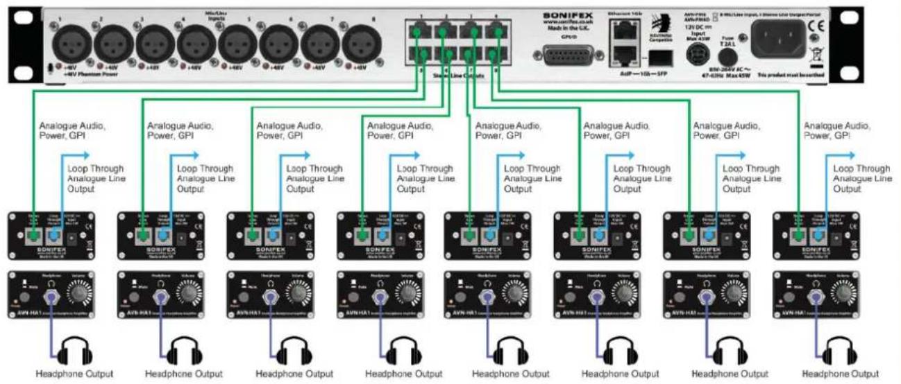
The portals can be combined with the Sonifex AVN-HA1 and AVN-HD1 headphone amplifiers to provide 8 separate headphone signals where each headphone amplifier can be sent a separate feed, mixed from any physical or stream inputs. On portal units with RJ45 outputs, an AVN-HA1 (for the AVN-PA8 and AVN-PM8) of AVN-HD1 (for the AVN-PD8) headphone amplifier can be used to listen to the outputs, with the portals providing power and audio signals. The switches on the front panel of the AVN-HA1 and AVN-HD1 can be used as another GPI for muting the output (in the GPIO settings menu these are known as 'Cough Ports'). Please refer to the Sonifex or website for more information on the AVN-HA1 and AVN-HD1 headphone amplifiers.
Headphone Distribution System Using Analogue Portals (AVN-PA8, AVN-PA8D, AVN-PM8, AVN-PM8D) & 8 x AVN-HA1 Units
flowchart
graph TD
    A["SONIFEX"] -->|Analog Audio, Power, GPI| B["Headphone Output"]
    A -->|Analog Audio, Power, GPI| C["Headphone Output"]
    A -->|Analog Audio, Power, GPI| D["Headphone Output"]
    A -->|Analog Audio, Power, GPI| E["Headphone Output"]
    A -->|Analog Audio, Power, GPI| F["Headphone Output"]
    A -->|Analog Audio, Power, GPI| G["Headphone Output"]
    A -->|Analog Audio, Power, GPI| H["Headphone Output"]
    A -->|Analog Audio, Power, GPI| I["Headphone Output"]
    A -->|Analog Audio, Power, GPI| J["Headphone Output"]
    A -->|Analog Audio, Power, GPI| K["Headphone Output"]
    A -->|Analog Audio, Power, GPI| L["Headphone Output"]
    A -->|Analog Audio, Power, GPI| M["Headphone Output"]
    A -->|Analog Audio, Power, GPI| N["Headphone Output"]
    A -->|Analog Audio, Power, GPI| O["Headphone Output"]
    A -->|Analog Audio, Power, GPI| P["Headphone Output"]
    A -->|Analog Audio, Power, GPI| Q["Headphone Output"]
    A -->|Analog Audio, Power, GPI| R["Headphone Output"]
    A -->|Analog Audio, Power, GPI| S["Headphone Output"]
    A -->|Analog Audio, Power, GPI| T["Headphone Output"]
    A -->|Analog Audio, Power, GPI| U["Headphone Output"]
    A -->|Analog Audio, Power, GPI| V["Headphone Output"]
    A -->|Analog Audio, Power, GPI| W["Headphone Output"]
    A -->|Analog Audio, Power, GPI| X["Headphone Output"]
    A -->|Analog Audio, Power, GPI| Y["Headphone Output"]
    A -->|Analog Audio, Power, GPI| Z["Headphone Output"]
    A -->|Analog Audio, Power, GPI| AA["Headphone Output"]
    A -->|Analog Audio, Power, GPI| AB["Headphone Output"]
    A -->|Analog Audio, Power, GPI| AC["Headphone Output"]
    A -->|Analog Audio, Power, GPI| AD["Headphone Output"]
    A -->|Analog Audio, Power, GPI| AE["Headphone Output"]
    A -->|Analog Audio, Power, GPI| AF["Headphone Output"]
    A -->|Analog Audio, Power, GPI| AG["Headphone Output"]
    A -->|Analog Audio, Power, GPI| AH["Headphone Output"]
    A -->|Analog Audio, Power, GPI| AI["Headphone Output"]
    A -->|Analog Audio, Power, GPI| AJ["Headphone Output"]
    A -->|Analog Audio, Power, GPI| AK["Headphone Output"]
    A -->|Analog Audio, Power, GPI| AL["Headphone Output"]
2 Quick Start Guide
2. Quick Start Guide
This section outlines the steps required to get an AVN portal setup and routing audio.
- Connect the upper Ethernet port to a suitable network to access the web server to configure the initial settings. By default, this port is configured to use the static IP address 192.168.0.100.
- Apply power to the unit via the IEC mains connection or via an externa 12V DC power supply.
-
Once the unit has started and the main screen is shown on the OLED display, open a web browser and connect to the unit by entering the URL: http://192.168.0.100 into the browser address bar. Once connected, the device information web page will be shown. 8.
-
On the web page, select Network from the configuration tab and 9. configure the Ethernet and AoIP ports to the required settings. The IP addresses assigned to the 2 ports must be on different subnets. For example, with the subnet mask on both ports set to 255.255.255.0, if the IP address on the Ethernet port is set to 192.168.0.100, the AoIP port must be set to 192.168.x.y where x is not 0 and y is unique on chosen subnet.
-
Although not essential at this point, it is a good idea to assign a recognisable friendly name so that other users can easily identify and use services from this unit.
-
To simplify the configuration process, make sure the Auto Multicast 10 option is enabled. This removes the need to set the transmit AoIP multicast IP addresses as they will be configured automatically based on the AoIP port IP address. Once the settings on the network page11 have been configured, press the submit button to save them to the connected unit. When the network settings have been changed, the unit will automatically restart. If the settings of the network port the2 browser is connected to have changed, a new browser connection will need to be established using the new IP address. If dynamic address mode has been selected, the active IP address for the network port ca
be found by going to the system info menu on the front panel. See System Info menu item for details.
- If a dedicated grandmaster clock, such as the AVN-GMC from Sonifex, is going to be used as the master PTP clock for the network audio system, the PTP profile on the portal will need to be set to the current setting on the grandmaster device. On the web page, select PTP Profiles from the configuration tab. Select the required profile from the drop-down panel list box and ensure that the domain number for the selected profile matches the grandmaster setting. Press the submit button to save the new settings. If no dedicated grandmaster device is used, all PTP aware the devices in the network will automatically establish a master clock hierarchy. In this case, the default profile can be used.
- Connect the lower AoIP port to the audio network.
- On the web page, select Audio Routing from the Configuration tab. A IP routing grid can now be seen with inputs down the left-hand side and outputs along the top. By clicking on a square in the routing table, the if channels for the input and output corresponding to that square will be shown, clicking the square at which two channels meet routes the on the input channel to the output channel. Where an input is routed to an output, the square will be highlighted in green. Clicking on an existing routing raises a dialog box which allows the user to modify the mix level or remove the routing. (An existing routing can also be removed by holding the Ctrl key and clicking on it).
- AoIP input streams can be added to the routing grid by clicking 'Add AoIP In Stream'. A dialog box will be shown containing a list of the discovered AoIP streams. Select a stream from the list and click 'Add'.
- AoIP output streams can be added to the routing table by clicking 'Add AoIP Out Stream'. A dialog box will be shown and a stream can be set up by typing in an AoIP stream name and clicking 'Add'.
- Clicking on the name of an input or output raises a dialog which allows various settings such as Trim and EQ of the input or output to be adjusted.
3. Installation
Network Connection
All devices in the AVN portal series have two gigabit ethernet network ports.
Upper Port: Configuration and control interface. Lower Port: Audio over IP (AoIP) interface.
In an ideal installation, the lower port should be connected to a dedicated network switch that handles audio and audio related traffic only. All other AoIP sources and destinations, and grandmaster clocks should be connected to this network. The upper port can then be connected to a separate network to provide access to the embedded web server. With setup, potentially heavy network traffic on a company LAN does not affit the performance of the AoIP network.
The AVN portals can be used with a single network connection using the lower (AoIP) port as this also provides access to the embedded web set. The AoIP sources and destinations, and grandmaster clocks should still ideally be connected to a dedicated network switch.
Audio Inputs
The AVN-PA8 has 8 analogue balanced stereo inputs. The AVN-PD8 has digital AES3 inputs and the AVN-PM8 has 8 balanced mono mic/line input. These audio inputs can be monitored using the meter display if fitted, otherwise confidence metering is available on the OLED display. These inputs can be routed to any of the devices physical outputs and any of AoIP output streams. This routing can be controlled through the devices webserver.
Audio Outputs
The AVN-PA8 has 8 analogue balanced stereo outputs. The AVN-PD8 has 8 digital AES3 outputs and the AVN-PM8 has 8 analogue balanced stereo outputs. These audio outputs can be monitored using the meter display if fitted, otherwise confidence metering is available on the OLED display. The audio sent to these outputs can be routed from any of the physical and AoIP input streams. This routing is controlled through the webserver.
ted GPIO
All devices in the AVN portal series have a GPIO connector, this GPIO connector provides the device with 10 physical GPIO ports and a single output relay. Each GPIO port can be disabled, used as an input or used as a output. All devices in the series also have 10 virtual GPIO ports available. All GPIO and relay settings can be configured through the devices webserver. All units with RJ45 type outputs provide an extra 8 GPI ports that can be used in conjunction with the AVN-HA1 (for the AVN-PA8 and AVN-PM8) or AVN-HD1 (for the AVN-PD8). The settings for these GPIO ports can also be configured through the webserver and are known as Cough Ports.
Power Supply
The unit can be powered from the mains via the supplied IEC lead, or by using the optional external 12V DC power supply, part number AVN-DC150. Please contact Sonifex Ltd sales for more details. Both power supplies can be connected and powered at the same time to provide redundancy if required.
4. Front Panel Controls, Indicators & Displays
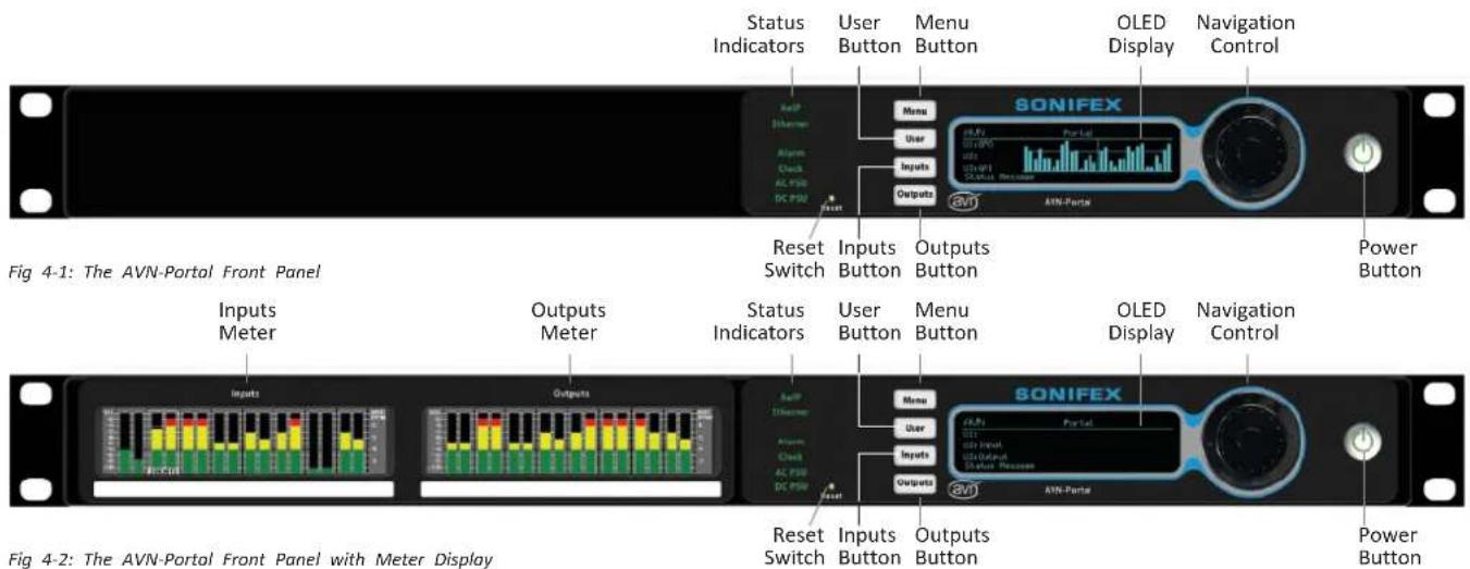
Status Indicators
The RGB status indicators are located on the left side of the main display. Indicates the link status of the Ethernet port (upper network connector).
AoIP
Indicates the link status of the AoIP port (lower network connector).
Green The link is up.
Off The link is down.
The AoIP network interface is configured through the embedded web server.
Ethernet
Indicates the link status of the Ethernet port (upper network connector).
Green The link is up.
Off The link is down.
The Ethernet network interface is configured through the embedded web server.
Alarm
This status LED is not currently used but is reserved for future use.
Front Panel Controls, Indicators CE Conformity
Clock
Indicates the status of PTP clock as follows.
Green The unit is a PTP slave with a clock offset of less or equal to ±1 s or the unit is the PTP master.
Amber The unit is a PTP slave with a clock offset of between ±1 s and ±10 s .
Flash Amber The unit is in a listening state and is not yet acting as the master or a slave.
Red The unit is a PTP slave with a clock offset of greater than ±10 s .
Flash Red The unit is a PTP slave and no master is available.
The devices PTP settings can be configured through the embedded web server.
AC PSU
Indicates the status of the internal AC-DC power supply as follows.
Green AC-DC generated voltage is within normal operating range of +11V to +13V. This is the normal condition.
Amber AC-DC generated voltage is less than +11V or greater than +13V. This indicates a warn condition.
Red AC-DC generated voltage is less than +10V or greater than +14V. This indicates a fault condition if an AC power source connected.
DC PSU
Indicates the status of the DC power input as follows:
Green DC voltage is within normal operating range of +11V to +13V. This is the normal condition.
Amber DC voltage is less than +11V or greater than +13V. This indicates a warn condition.
Red Not connected or DC voltage is less than +10V or greater than +14V. This indicates a fault condition if a DC power source is connected.
NB: Both the AC PSU and DC PSU LEDs can be disabled via the Display Settings web page menu.
Menu Button
Press the menu button to open the front panel main menu. Pressing the button whilst in the menu will close the menu. (The main menu can also be opened by pressing and holding the centre button of the rotary control for 3 seconds).
User Buttons
There are three user buttons on the devices front panel, each one of these buttons can be configured to control various functions on the unit. Information on configuring these buttons can be found here.
these buttons are currently labelled "Menu", "Inputs" and "Outputs" however the labels can be changed to match the configured function.
OLED Display
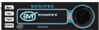
Fig 4 3: Main OLED Display
The portals OLED display shows useful system information and allows the user to view and change device settings from the front panel. The display
CE Conformity | Controls, Indicators & Displays
shows the device ID, friendly name, the user button settings, and on devices without a meter panel, confidence metering of the physical input on the left and the physical outputs on the right (see Fig 4-1).
By holding the centre button of the controls, the user can enter the devices main menu. The user can then use the left and right buttons to move in and out of menus, the up and down buttons or rotary control to move up and down menus and the centre button to move into menus.
Each of the portals can be ordered with input/output metering displays version). These displays show active level metering of the audio at the input and output of the device. An individual input and output can be selected to take up the full display to show a more detailed view of the level. The layout of the metering and type of scale used can be varied either the front panel menu or the embedded web server.
The name of each input and output can also be seen and can be configured to show above the metering, show below the metering, or to be hidden.
Navigation Control
The navigation control, located to the right of the OLED display, can be used to select a stereo input (AVN-PA8 and AVN-PD8) or mono input (AVN-PM8) on the input meter display, or a stereo output on the output meter display. The selected channel or channels will be shown in more detail using the whole screen. To select whether to access the input or output meter display, use the up and down buttons on the navigation control, an individual input or output channel can then be selected using the scroll wheel or the left and right keys and pressing the centre key to confirm.
Reset Button
The recessed reset button is located to the right of the LED status indicators on the front panel and can be used to perform a full hardware reset on the unit.
Power Button
The power button turns the unit on and off. When the unit is on, the indicator is green. When the unit is off, the indicator is red. The power button is disabled by default and can be enabled through the "Display Settings" web page.
5. AVN-PA8/T/D 8 Stereo Analogue Line Inputs & Outputs, AES67 Display Portal
Rear Panel Connections
AVN-PA8/AVN-PA8D 8 Stereo Analogue Line Inputs & Outputs
AES67 Display Portal
D-Sub (DB-25) Stereo Line Input Connections
The AVN-PA8 and AVN-PA8D have 2 female D-Sub (DB-25) input
connections with a TASCAM AES-59 analogue pinout, these connections
paralleled with the 8 RJ45 input connections. This has the following pin
TASCAM AES-59 analogue pinout.
Pin 1: Channel 8 + (Phase)
Pin 2: Channel 8 ground
Pin 3: Channel 7 - (Non-phase)
Pin 4: Channel 6 + (Phase)
Pin 5: Channel 6 ground
Pin 6: Channel 5 - (Non-phase)
Pin 7: Channel 4 + (Phase)
Pin 8: Channel 4 ground
Pin 9: Channel 3 - (Non-phase)
Pin 10: Channel 2 + (Phase)
Pin 11: Channel 2 ground
Pin 12: Channel 1 - (Non-phase)
Pin 13: No connection
Pin 14: Channel 8 - (Non-phase)
Pm 15: Channel 7 + (Phase)
Pin 16: Channel 7 ground
Pin 17: Channel 6 - (Non-phase)
Pin 18: Channel 5 + (Phase)
Pin 19: Channel 5 ground
Pin 20: Channel 4 - (Non-phase)
Pin 21: Channel 3 + (Phase)
Pin 22: Channel 3 ground
Pin 23: Channel 2 - (Non-phase)
Pin 24: Channel 1 + (Phase)
Pin 25: Channel 1 ground

Fig 5-1: AVN-PA8/AVN-PA8D Rear Panel
5 AVN-PA8/T/D
RJ45 Stereo Line Input Connections
The AVN-PA8 and AVN-PA8D have 8 female analogue RJ45 inputs. AnalogPin 13: No connection RJ45s connections for inputs use the StudioHub+ pinout, these connectionPin 14: Channel 8 - (Non-phase) are paralleled with the D-Sub (DB-25) connections. This has the followingPin 15: Channel 7 + (Phase) pinout. Pin 16: Channel 7 ground
StudioHub+ pinout.
Pin 1: I/O Left + (Phase) Pin 2: I/O Left - (Non-phase) Pin 3: I/O Right + (Phase)
Pin 4: Ground
Pin 5: No connection
Pin 6: I/O Right - (Non-phase)
Pin 7: No connection
Pin 8: +12V
D-Sub (DB-25) Stereo Line Output Connections
The AVN-PA8 and AVN-PA8D have 2 female D-Sub (DB-25) output connections with a TASCAM AES-59 analogue pinout, these connections paralleled with the 8 RJ45 output connections. This has the following pinout.
TASCAM AES-59 analogue pinout.
Pin 1: Channel 8 + (Phase)
Pin 2: Channel 8 ground
Pin 3: Channel 7 – (Non-phase)
Pin 4: Channel 6 + (Phase)
Pin 5: Channel 6 ground
Pin 6: Channel 5 – (Non-phase)
Pin 7: Channel 4 + (Phase)
Pin 8: Channel 4 ground
Pin 9: Channel 3 - (Non-phase)
Pin 10: Channel 2 + (Phase)
Pin 11: Channel 2 ground
Pin 12: Channel 1 – (Non-phase)
gPie 13: No connection
rBin 14: Channel 8 - (Non-phase)
gPin 15: Channel 7 + (Phase)
Pin 16: Channel 7 ground
Pin 17: Channel 6 – (Non-phase)
Pin 18: Channel 5 + (Phase)
Pin 19: Channel 5 ground
Pin 20: Channel 4 – (Non-phase)
Pin 21: Channel 3 + (Phase)
Pin 22: Channel 3 ground
Pin 23: Channel 2 – (Non-phase)
Pin 24: Channel 1 + (Phase)
Pin 25: Channel 1 ground
RJ45 Stereo Line Output Connections
The AVN-PA8 and AVN- PA8D have 8 female analogue RJ45 outputs.
Analogue RJ45s connections for outputs use the StudioHub+ pinout, these are connections are paralleled with the D-Sub (DB-25) connections. This has the following pinout.
StudioHub+ pinout.
Pin 1: I/O Left + (Phase)
Pin 2: I/O Left - (Non-phase)
Pin 3: I/O Right + (Phase)
Pin 4: Ground
Pin 5: Cough/Mute (Active low)
Pin 6: I/O Right - (Non-phase)
Pin 7: No connection
Pin 8: +12V
D-Sub (DA-15) GPIO Connection
The AVN-PA8 and AVN-PA8D have a single female D-Sub (DA-15)
connection, this provides 10 configurable GPIO and a voltage free switching relay contact. This has the following pinout.
AVN-PA8/T/D 5
Pin 1: GPIO Port 1
Pin 2: GPIO Port 2
Pin 3: GPIO Port 3
Pin 4: GPIO Port 4
Pin 5: GPIO Port 5
Pin 6: Relay - Normally Open Contact
Pin 7: Relay - Normally Closed Contact
Pin 8: Relay - Common
Pin 9: GPIO Port 6
Pin 10: GPIO Port 7
Pin 11: GPIO Port 8
Pin 12: GPIO Port 9
Pin 13: GPIO Port 10
Pin 14: Fused (200mA) +12VDC Supply
Pin 15: Ground
The +12V supply is fused and has a maximum output current of 200mA.
GPIO ports can be set up as GPO or GPI. GPO are open collector, this the output pin is connected to ground when the GPO is active. GPI are active low this means they are triggered when pulled down to ground. configuration can be managed through the embedded web server.
AVN-PA8T/AVN-PA8TD 24-Pin Phoenix Style Stereo Line Input/Output Terminal Connections, AES67 Portal
24-Pin Phoenix Style Stereo Line Input Terminal Connections
The AVN-PA8T and AVN-PA8TD have 2 female 24-pin Phoenix style terminal blocks used as analogue stereo line inputs. This has the following pinout.
L - Left
R - Right
Block 1
Pin 1: Channel 1L ground
Pin 2: Channel 1L + (Phase)
Pin 3: Channel 1L - (Non-phase)
Pin 4: Channel 1R ground
Pin 5: Channel 1R + (Phase)
Pin 6: Channel 1R - (Non-phase)
Maans Channel 2L ground
Pin 8: Channel 2L + (Phase)
PHO9: Channel 2L - (Non-phase)
Pin 10: Channel 2R ground
Pin 11: Channel 2R + (Phase)
Pin 12: Channel 2R - (Non-phase)

5 AVN-PA8/T/D
Pin 13: Channel 3L ground
Pin 14: Channel 3L + (Phase)
Pin 15: Channel 3L - (Non-phase)
Pin 16: Channel 3R ground
Pin 17: Channel 3R + (Phase)
Pin 18: Channel 3R - (Non-phase)
Pin 19: Channel 4L ground
Pin 20: Channel 4L + (Phase)
Pin 21: Channel 4L - (Non-phase)
Pin 22: Channel 4R ground
Pin 23: Channel 4R + (Phase)
Pin 24: Channel 4R - (Non-phase)
Block 2
Pin 1: Channel 5L ground
Pin 2: Channel 5L + (Phase)
Pin 3: Channel 5L - (Non-phase)
Pin 4: Channel 5R ground
Pin 5: Channel 5R + (Phase)
Pin 6: Channel 5R - (Non-phase)
Pin 7: Channel 6L ground
Pin 8: Channel 6L + (Phase)
Pin 9: Channel 6L - (Non-phase)
Pin 10: Channel 6R ground
Pin 11: Channel 6R + (Phase)
Pin 12: Channel 6R - (Non-phase)
Pin 13: Channel 7L ground
Pin 14: Channel 7L + (Phase)
Pin 15: Channel 7L - (Non-phase)
Pin 16: Channel 7R ground
Pin 17: Channel 7R + (Phase)
Pin 18: Channel 7R - (Non-phase)
Pin 19: Channel 8L ground
Pin 20: Channel 8L + (Phase)
Pin 21: Channel 8L - (Non-phase)
Pin 22: Channel 8R ground
Pin 23: Channel 8R + (Phase)
Pin 24: Channel 8R - (Non-phase)
24-Pin Phoenix Style Stereo Line Output Terminal Connections
The AVN-PA8T and AVN-PA8TD have 2 female 24-pin Phoenix style terminal blocks used as analogue stereo line outputs.
L - Left
R - Right
Block 1
Pin 1: Channel 1L ground
Pin 2: Channel 1L + (Phase)
Pin 3: Channel 1L - (Non-phase)
Pin 4: Channel 1R ground
Pin 5: Channel 1R + (Phase)
Pin 6: Channel 1R - (Non-phase)
Pin 7: Channel 2L ground
Pin 8: Channel 2L + (Phase)
Pin 9: Channel 2L - (Non-phase)
Pin 10: Channel 2R ground
Pin 11: Channel 2R + (Phase)
Pin 12: Channel 2R - (Non-phase)
Pin 13: Channel 3L ground
Pin 14: Channel 3L + (Phase)
Pin 15: Channel 3L - (Non-phase)
Pin 16: Channel 3R ground
Pin 17: Channel 3R + (Phase)
Pin 18: Channel 3R - (Non-phase)
AVN-PA8/T/D 5
Pin 19: Channel 4L ground
Pin 20: Channel 4L + (Phase)
Pin 21: Channel 4L - (Non-phase)
Pin 22: Channel 4R ground
Pin 23: Channel 4R + (Phase)
Pin 24: Channel 4R - (Non-phase)
Block 2
Pin 1: Channel 5L ground
Pin 2: Channel 5L + (Phase)
Pin 3: Channel 5L - (Non-phase)
Pin 4: Channel 5R ground
Pin 5: Channel 5R + (Phase)
Pin 6: Channel 5R - (Non-phase)
Pin 7: Channel 6L ground
Pin 8: Channel 6L + (Phase)
Pin 9: Channel 6L - (Non-phase)
Pin 10: Channel 6R ground
Pin 11: Channel 6R + (Phase)
Pin 12: Channel 6R - (Non-phase)
Pin 13: Channel 7L ground
Pin 14: Channel 7L + (Phase)
Pin 15: Channel 7L - (Non-phase)
Pin 16: Channel 7R ground
Pin 17: Channel 7R + (Phase)
Pin 18: Channel 7R - (Non-phase)
Pin 19: Channel 8L ground
Pin 20: Channel 8L + (Phase)
Pin 21: Channel 8L - (Non-phase)
Pin 22: Channel 8R ground
Pin 23: Channel 8R + (Phase)
Pin 24: Channel 8R - (Non-phase)
24-Pin Phoenix Style GPIO Terminal Connection
The AVN-PA8T and AVN-PA8TD have a single female Phoenix style terminal block, this provides 10 configurable GPIO and a voltage free switching relay contact.
Pin 1: +12VDC
Pin 2: GPIO Port 1
Pin 3: GPIO Port 2
Pin 4: Ground
Pin 5: +12VDC
Pin 6: GPIO Port 3
Pin 7: GPIO Port 4
Pin 8: Ground
Pin 9: +12VDC
Pin 10: GPIO Port 5
Pin 11: GPIO Port 6
Pin 12: Ground
Pin 13: +12VDC
Pin 14: GPIO Port 7
Pin 15: GPIO Port 8
Pin 16: Ground
Pin 17: +12VDC
Pin 18: GPIO Port 9
Pin 19: GPIO Port 10
Pin 20: Ground
Pin 21: Relay - Normally Closed Contact
Pin 22: +12VDC
Pin 23: Relay - Common
Pin 24: Relay - Normally Open Contact
The +12V supply is fused and has a maximum output current of 200mA.
5 AVN-PA8/T/D
GPIO ports can be set up as GPO or GPI. GPO are open collector, this means DC Input
the output pin is connected to ground when the GPO is active. GPI are This 4-pin connector allows an external +12V power supply to be used to active low this means they are triggered when pulled down to ground. GPOver the unit. Both the 12V DC input and the mains AC input can be configuration can be managed through the devices embedded web server connected at the same time, this provides redundancy if needed.
Network Interfacing RJ45 Connections
In an ideal installation, the lower port should be connected to a dedicated network switch that handles audio and audio related traffic only. All other AoIP sources and destinations, and grandmaster clocks should be connected to this network. The upper port can then be connected to a separate network to provide access to the embedded web server. With this setup, potentially heavy network traffic on a company LAN does not affect the performance of the AoIP network.
Ethernet
All devices in the AVN portal series have a female RJ45 used for network interfacing, this is the top port and is used to access the devices embedded in web server.
AoIP
All devices in the AVN portal series have a female RJ45 used for audio transfer and network interfacing, this is the bottom port and is used primarily to transfer audio across a network, however it can also be us access the devices embedded web server.
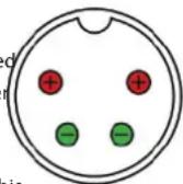
5-3: 4-Pin Circular DIN
As long as the DC power supply used provides +12V to either of the top pins and 0V to either of the bottom pins the unit will be powered, even if the other two pins are incorrect. For example, if a DC power supply has two work +12V pins on the right and two 0V pins on the left, this is still compatible. Therefore, the only invalid configuration is if both bottom pins are supplied with +12V and both top pins are supplied with 0V.
Mains Fuse
This 20mm x 5mm anti-surge mains fuse is rated at 2A.
Mains AC Input
This universally filtered IEC is the mains AC input power supply to the unit.
SFP Interface
AoIP
All units in the portal series are fitted with an SFP (Small Form-factor Pluggable) port this allows the user to install a SFP transceiver of their choice such as a 1Gbit/s copper or optical SFP transceiver. The AoIP network interfacing RJ45 connection cannot be used at the same time as the SFP interface.
6. AVN-PD8/T/D 8 Stereo Digital Line Inputs & Outputs, AES67 Portal
Rear Panel Connections
AVN-PD8/AVN-PD8D
D-Sub (DB-25) Stereo Digital Inputs And Outputs
The AVN-PD8 and AVN-PD8D have 2 female digital D-Sub (DB-25) inputs outputs. These inputs and outputs are in parallel with the RJ45 stereo digital inputs and outputs.
TASCAM AES-59 digital pinout.
Pin 1: Out Channel 7/8 + (Phase)
Pin 2: Out Channel 7/8 ground
Pin 3: Out Channel 5/6 - (Non-phase)
Pin 4: Out Channel 3/4 + (Phase)
Pin 5: Out Channel 3/4 ground
Pin 6: Out Channel 1/2 - (Non-phase)
Pin 7: In Channel 7/8 + (Phase)
Pin 8: In Channel 7/8 ground
Pin 9: In Channel 5/6 - (Non-phase)
Pin 10: In Channel 3/4 + (Phase)
Pin 11: In Channel 3/4 ground
Pin 12: In Channel 1/2 - (Non-phase)
Pin 13: No connection
Pin 14: Out Channel 7/8 - (Non-phase)
Pin 15: Out Channel 5/6 + (Phase)
Pin 16: Out Channel 5/6 ground
Pin 17: Out Channel 3/4 - (Non-phase)
and Pin 18: Out Channel 1/2 + (Phase)
Pin 19: Out Channel 1/2 ground
Pin 20: In Channel 7/8 - (Non-phase)
Pin 21: In Channel 5/6 + (Phase)
Pin 22: In Channel 5/6 ground
Pin 23: In Channel 3/4 - (Non-phase)
Pin 24: In Channel 1/2 + (Phase)
Pin 25: In Channel 1/2 ground
RJ45 Stereo Digital Inputs and Outputs
The AVN-PD8 and AVN-PD8D have 8 female digital RJ45 inputs and 8 digital RJ45 outputs.
StudioHub+ pinout.
Pin 1: I/O AES + (Phase)
Pin 2: I/O AES - (Non-phase)
Pin 3: No connection
Pin 4: Ground

Fig 6-1: AVN-PD8/AVN-PD8D Rear Panel
6 AVN-PD8/T/D
Pin 5: Inputs - No connection. Outputs - Cough/Mute (Active Low)
Pin 6: No connection
Pin 7: No connection
Pin 8: +12V
D-Sub (DA-15) GPIO Connection
The AVN-PD8 and AVN-PD8D have a single female D-Sub (DA-15)
connection, this provides 10 configurable GPIO and a voltage free switching AVN-PD8T/ AVN-PD8TD 24-Pin Phoenix Style Stereo Line Input/relay contact. Output Terminal Connections. AES67 Portal
Pin 1: GPIO Port 1
Pin 2: GPIO Port 2
Pin 3: GPIO Port 3
Pin 4: GPIO Port 4
Pin 5: GPIO Port 5
Pin 6: Relay - Normally Open Contact
Pin 7: Relay - Normally Closed Contact
Pin 8: Relay - Common
Pin 9: GPIO Port 6
Pin 10: GPIO Port 7
Pin 11: GPIO Port 8
Pin 12: GPIO Port 9
Pin 13: GPIO Port 10
Pin 14: Fused (200mA) +12VDC Supply
Pin 15: Ground
The +12V supply is fused and has a maximum output current of 200mA.
GPIO ports can be set up as GPO or GPI. GPO are open collector, this means the output pin is connected to ground when the GPO is active. GPI are active low this means they are triggered when pulled down to ground. GPIO configuration can be managed through the devices embedded web server.
ingVN-PD8T/ AVN-PD8TD 24-Pin Phoenix Style Stereo Line Input/Output Terminal Connections, AES67 Portal
24-Pin Phoenix Style Stereo Digital Input Terminal Connection
The AVN-PD8T and AVN-PD8TD use female Phoenix style terminal blocks.
Pin 1: Channel 1/2 ground
Pin 2: Channel 1/2 + (Phase)
Pin 3: Channel 1/2 - (Non-phase)
Pin 4: Channel 3/4 ground
Pin 5: Channel 3/4 + (Phase)
Pin 6: Channel 3/4 - (Non-phase)
Pin 7: Channel 5/6 ground
Pin 8: Channel 5/6 + (Phase)
Pin 9: Channel 5/6 - (Non-phase)
Pin 10: Channel 7/8 ground
Pin 11: Channel 7/8 + (Phase)
Pin 12: Channel 7/8 - (Non-phase)
Pin 13: Channel 9/10 ground
24-Pin Phoenix Style Stereo Line Input Terminal Connections
24-Pin Phoenix Style GPIO
Terminal Connection
Ethernet 1 Gb 12V DC Female RJ45 Input
Mains AC Input

24-Pin Phoenix Style Stereo Line Output Terminal Connections
AoIP 1Gb SFP Mains Female RJ45 Port Fuse
Fig 6-2: AVN-PD8T/AVN-PD8TD Rear Panel
AVN-PD8/T/D 6
Pin 14: Channel 9/10 + (Phase)
Pin 15: Channel 9/10 - (Non-phase)
Pin 16: Channel 11/12 ground
Pin 17: Channel 11/12 + (Phase)
Pin 18: Channel 11/12 - (Non-phase)
Pin 19: Channel 13/14 ground
Pin 20: Channel 13/14 + (Phase)
Pin 21: Channel 13/14 - (Non-phase)
Pin 22: Channel 15/16 ground
Pin 23: Channel 15/16 + (Phase)
Pin 24: Channel 15/16 - (Non-phase)
24-Pin Phoenix Style Stereo Digital Output Terminal Connection
Pin 18: Channel 11/12 - (Non-phase)
Pin 19: Channel 13/14 ground
Pin 20: Channel 13/14 + (Phase)
Pin 21: Channel 13/14 - (Non-phase)
Pin 22: Channel 15/16 ground
Pin 23: Channel 15/16 + (Phase)
Pin 24: Channel 15/16 - (Non-phase)
24-Pin Phoenix Style GPIO Terminal Connection
The AVN-PD8T and AVN-PD8TD have a single female Phoenix style terminal block, this provides 10 configurable GPIO and a voltage free switching relay contact.
The AVN-PD8T and AVN-PD8TD use female Phoenix style terminal blocks.
| Pin 1: Channel 1/2 ground |
| Pin 2: Channel 1/2 + (Phase) |
| Pin 3: Channel 1/2 - (Non-phase) |
| Pin 4: Channel 3/4 ground |
| Pin 5: Channel 3/4 + (Phase) |
| Pin 6: Channel 3/4 - (Non-phase) |
| Pin 7: Channel 5/6 ground |
| Pin 8: Channel 5/6 + (Phase) |
| Pin 9: Channel 5/6 - (Non-phase) |
| Pin 10: Channel 7/8 ground |
| Pin 11: Channel 7/8 + (Phase) |
| Pin 12: Channel 7/8 - (Non-phase) |
| Pin 13: Channel 9/10 ground |
| Pin 14: Channel 9/10 + (Phase) |
| Pin 15: Channel 9/10 - (Non-phase) |
| Pin 16: Channel 11/12 ground |
| Pin 17: Channel 11/12 + (Phase) |
Pin 1: +12VDC
Pin 2: GPIO Port 1
Pin 3: GPIO Port 2
Pin 4: Ground
Pin 5: +12VDC
Pin 6: GPIO Port 3
Pin 7: GPIO Port 4
Pin 8: Ground
Pin 9: +12VDC
Pin 10: GPIO Port 5
Pin 11: GPIO Port 6
Pin 12: Ground
Pin 13: +12VDC
Pin 14: GPIO Port 7
Pin 15: GPIO Port 8
Pin 16: Ground
Pin 17: +12VDC
Pin 18: GPIO Port 9
Pin 19: GPIO Port 10
6 AVN-PD8/T/D
Pin 20: Ground
Pin 21: Relay - Normally Closed Contact
Pin 22: +12VDC
Pin 23: Relay - Common
Pin 24: Relay - Normally Open Contact
The +12V supply is fused and has a maximum output current of 200mA.
GPIO ports can be set up as GPO or GPI. GPO are open collector, this is the output pin is connected to ground when the GPO is active. GPI are active low this means they are triggered when pulled down to ground. C configuration can be managed through the devices embedded web server
Network Interfacing RJ45 Connections
In an ideal installation, the lower port should be connected to a dedicated network switch that handles audio and audio related traffic only. All other AoIP sources and destinations, and grandmaster clocks should be connected to this network. The upper port can then be connected to a separate network to provide access to the embedded web server. With this setup, potentially heavy network traffic on a company LAN does not affect the performance of the AoIP network.
Ethernet
All devices in the AVN portal series have a female RJ45 used for network interfacing, this is the top port and is used to access the devices embed web server.
AoIP
All devices in the AVN portal series have a female RJ45 used for audio transfer and network interfacing, this is the bottom port and is used primarily to transfer audio across a network, however it can also be us access the devices embedded web server.
SFP Interface
AoIP
All units in the portal series are fitted with an SFP (Small Form-factor Pluggable) port this allows the user to install a SFP transceiver of their choice such as a 1Gbit/s copper or optical SFP transceiver. The AoIP network interfacing RJ45 connection cannot be used at the same time as the SFP interface.
12V DC Input
This 4-pin connector allows an external +12V power supply to be used to power the unit. Both the 12V DC input and the mains AC input can be connected at the same time, this provides redundancy if needed.
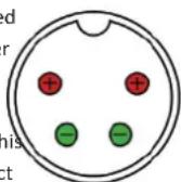
Fig 6-3: 4-Pin Circular DIN
As long as the DC power supply used provides +12V to either of the top pins and 0V to either of the bottom pins the unit will be powered, even if the other two pins are incorrect. For example, if a DC power supply has two
+12V pins on the right and two 0V pins on the left, this is still compatible. Therefore, the only invalid configuration is if both bottom pins are supplied with +12V and both top pins are supplied with 0V.
Mains Fuse
ethio 20mm x 5mm anti-surge mains fuse is rated at 2A.
Mains AC Input
This universally filtered IEC is the mains AC input power supply to the unit.
7. AVN-PM8/T/D 8 Mic/Line Inputs, 8 Line Outputs, Terminal Block, AES67 Portal
Rear Panel Connections
AVN-PM8/AVN-PM8D
XLR Mic/Line Inputs
The AVN-PM8 and AVN-PM8D have 8 female XLR connections used as microphone inputs.
Pin 1: Ground
Pin 2: Microphone Phase
Pin 3: Microphone Non-Phase
Phantom power and rear panel LEDs
Phantom power can be enabled on each of the microphone inputs, this done through the devices embedded web server, if a microphone input Phantom power enabled the corresponding LED will light up on the back panel of the device.
RJ45 Stereo Line Output Connections
The AVN-PM8 and AVN-PM8D have 8 female analogue RJ45 outputs.
Analogue RJ45s connections for outputs use the StudioHub+ pinout, these connections are paralleled with the D-Sub (DB-25) connections.
StudioHub+ pinout.
Pin 1: I/O Left + (Phase)
Pin 2: I/O Left - (Non-phase)
Pin 3: I/O Right + (Phase)
Pin 4: Ground
Pin 5: Cough/Mute (Active low)
Pin 6: I/O Right - (Non-phase)
Pin 7: No connection
Pin 8: +12V
D-Sub (DA-15) GPIO connection
The AVN-PM8 and AVN-PM8D have a single female D-Sub (DA-15)
connection, this provides 10 configurable GPIO and a voltage free switching relay contact.
*Pin 1: GPIO Port 1
Pin 2: GPIO Port 2
Pin 3: GPIO Port 3
Pin 4: GPIO Port 4
Pin 5: GPIO Port 5
Pin 6: Relay - Normally Open Contact
Pin 7: Relay - Normally Closed Contact
Pin 8: Relay - Common

7 AVN-PM8/T/D
Pin 9: GPIO Port 6
Pin 10: GPIO Port 7
Pin 11: GPIO Port 8
Pin 12: GPIO Port 9
Pin 13: GPIO Port 10
Pin 14: Fused (200mA) +12VDC Supply
Pin 15: Ground
The +12V supply is fused and has a maximum output current of 200mA.
GPIO ports can be set up as GPO or GPI. GPO are open collector, this the output pin is connected to ground when the GPO is active. GPI are active low this means they are triggered when pulled down to ground. configuration can be managed through the devices embedded web serve
AVN-PM8T/ AVN-PM8TD 24-Pin Phoenix Style Stereo Line Input Output Terminal Connections, AES67 Portal
24-Pin Phoenix Style Stereo Line Input Terminal Connections
The AVN-PM8T and AVN-PM8TD have a female 24-pin Phoenix style terminal blocks used for analogue mono line inputs.
Pin 1: Channel 1 ground
Pin 2: Channel 1 + (Phase)
Pin 3: Channel 1 - (Non-phase)
Pin 4: Channel 2 ground
Pin 5: Channel 2 + (Phase)
Pin 6: Channel 2 - (Non-phase)
Pin 7: Channel 3 ground
Pin 8: Channel 3 + (Phase)
Pin 9: Channel 3 - (Non-phase)
Pin 10: Channel 4 ground
Pin 11: Channel 4 + (Phase)
Pin 12: Channel 4 - (Non-phase)
Pin 13: Channel 5 ground
Pin 14: Channel 5 + (Phase)
Pin 15: Channel 5 - (Non-phase)
Pin 16: Channel 6 ground
Pin 17: Channel 6 + (Phase)
Pin 18: Channel 6 - (Non-phase)
Pin 19: Channel 7 ground
Pin 20: Channel 7 + (Phase)
Pin 21: Channel 7 – (Non-phase)
Pin 22: Channel 8 ground
Pin 23: Channel 8 + (Phase)
Pin 24: Channel 8 - (Non-phase)
24-Pin Phoenix Style Stereo Line Output Terminal Connections
The AVN-PM8T and AVN-PM8TD have 2 female 24-pin Phoenix style terminal blocks used as analogue stereo line outputs.
24-Pin Phoenix Style Stereo Line Input Terminal Connections
24-Pin Phoenix Style GPIO Terminal Connection
Ethernet 1 Gb 12V DC Female RJ45 Input
Mains AC Input

24-Pin Phoenix Style Stereo Line Output Terminal Connections
AoIP 1Gb SFP Female RJ45 Port
Mains Fuse
Fig 7-2: AVN-PM8T/AVN-PM8TD Rear Panel
AVN-PM8/T/D 7
L - Left
R - Right
Block 1
Pin 1: Channel 1L ground
Pin 2: Channel 1L + (Phase)
Pin 3: Channel 1L - (Non-phase)
Pin 4: Channel 1R ground
Pin 5: Channel 1R + (Phase)
Pin 6: Channel 1R - (Non-phase)
Pin 7: Channel 2L ground
Pin 8: Channel 2L + (Phase)
Pin 9: Channel 2L - (Non-phase)
Pin 10: Channel 2R ground
Pin 11: Channel 2R + (Phase)
Pin 12: Channel 2R - (Non-phase)
Pin 13: Channel 3L ground
Pin 14: Channel 3L + (Phase)
Pin 15: Channel 3L - (Non-phase)
Pin 16: Channel 3R ground
Pin 17: Channel 3R + (Phase)
Pin 18: Channel 3R - (Non-phase)
Pin 19: Channel 4L ground
Pin 20: Channel 4L + (Phase)
Pin 21: Channel 4L - (Non-phase)
Pin 22: Channel 4R ground
Pin 23: Channel 4R + (Phase)
Pin 24: Channel 4R - (Non-phase)
Block 2
Pin 1: Channel 5L ground
Pin 2: Channel 5L + (Phase)
Pin 3: Channel 5L - (Non-phase)
Pin 4: Channel 5R ground
Pin 5: Channel 5R + (Phase)
Pin 6: Channel 5R - (Non-phase)
Pin 7: Channel 6L ground
Pin 8: Channel 6L + (Phase)
Pin 9: Channel 6L - (Non-phase)
Pin 10: Channel 6R ground
Pin 11: Channel 6R + (Phase)
Pin 12: Channel 6R - (Non-phase)
Pin 13: Channel 7L ground
Pin 14: Channel 7L + (Phase)
Pin 15: Channel 7L - (Non-phase)
Pin 16: Channel 7R ground
Pin 17: Channel 7R + (Phase)
Pin 18: Channel 7R - (Non-phase)
Pin 19: Channel 8L ground
Pin 20: Channel 8L + (Phase)
Pin 21: Channel 8L - (Non-phase)
Pin 22: Channel 8R ground
Pin 23: Channel 8R + (Phase)
Pin 24: Channel 8R - (Non-phase)
24-Pin Phoenix Style GPIO Terminal Connection
The AVN-PM8T and AVN-PM8TD have a single female Phoenix style terminal I this provides 10 configurable GPIO and a voltage free switching relay contact.
Pin 1: +12VDC
Pin 2: GPIO Port 1
Pin 3: GPIO Port 2
Pin 4: Ground
Pin 5: +12VDC
Pin 6: GPIO Port 3
Pin 7: GPIO Port 4
Pin 8: Ground
Pin 9: +12VDC
Pin 10: GPIO Port 5
Pin 11: GPIO Port 6
7 AVN-PM8/T/D
Pin 12: Ground
Pin 13: +12VDC
Pin 14: GPIO Port 7
Pin 15: GPIO Port 8
Pin 16: Ground
Pin 17: +12VDC
Pin 18: GPIO Port 9
Pin 19: GPIO Port 10
Pin 20: Ground
Pin 21: Relay – Normally Closed Contact
Pin 22: +12VDC
Pin 23: Relay - Common
Pin 24: Relay - Normally Open Contact
The +12V supply is fused and has a maximum output current of 200mA.
GPIO ports can be set up as GPO or GPI. GPO are open collector, this is the output pin is connected to ground when the GPO is active. GPI are low this means they are triggered when pulled down to ground. GPIO configuration can be managed through the devices embedded web server
Network Interfacing RJ45 Connections
In an ideal installation, the lower port should be connected to a dedicated network switch that handles audio and audio related traffic only. All other AoIP sources and destinations, and grandmaster clocks should be connected to this network. The upper port can then be connected to a separate network to provide access to the embedded web server. With this setup, potentially heavy network traffic on a company LAN does not affect the performance of the AoIP network.
Ethernet
All devices in the AVN portal series have a female RJ45 used for network
interfacing, this is the top port and is used to access the devices embedded. Mains AC Input
web server.
AoIP
All devices in the AVN portal series have a female RJ45 used for audio transfer and network interfacing, this is the bottom port and is used primarily to transfer audio across a network, however it can also be used to access the devices embedded web server.
SFP Interface
AoIP
All units in the portal series are fitted with an SFP (Small Form-factor Pluggable) port this allows the user to install a SFP transceiver of their choice such as a 1Gbit/s copper or optical SFP transceiver. The AoIP network interfacing RJ45 connection cannot be used at the same time as the SFP interface.
12V DC Input
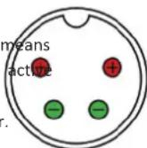
This 4-pin connector allows an external +12V power supply to be used to power the unit. Both the 12V DC input and the mains AC input can be connected at the same time, this provides redundancy if needed.
Fig 7-3: 4-Pin Circular DIN
Mains Fuse
This 20mm x 5mm anti-surge mains fuse is rated at 2A.
dated Mains AC Input
This universally filtered IEC is the mains AC input power supply to the unit.
Embedded Web Server 8
8. Embedded Web Server
The AVN portals have an embedded web server which provides easy to all the configuration options through a web browser. It also gives to system information and allows the firmware to be easily updated new releases are made available.
0.0.0.0. Once the IP address of the required port is known, simply type this into the address bar of a web browser. The 'Device Information' page of the cess connected AVN portal will be displayed. This is the default page and will cess always be displayed first when connecting to the embedded web server.
Each page of the web server shows the devices friendly name in the upper right-hand corner, under the product name. This makes it easier to identify
The device has two network interfacing RJ45 ports, these are located on the connected device, especially when configuring multiple devices at the devices back panel, either one of these ports can be used to connect the same time. The right-hand side of each page has a brief help section that device to a network, a computer on the same network can then access describes the content of each section.
devices embedded web server. The upper port is the general access '1Gb Ethernet' port and the lower port is the 'AolP' port. By default, both ports are set to static address mode with the upper port IP address set to 192.168.0.100 and the lower port IP address set to 192.168.1.100. If the network address mode for the port to be used has been set to 'Dynamic', the unit will attempt to acquire an IP address from a DHCP server, or if no DHCP server is found an automatically generated IP address will be used.
The active IP address for the network port can be found using a service discovery tool such as the 'Discovery Application' which can be found on the Sonifex website
(http://sonifex.co.uk/technical/software/index.shtml#sfxsrvdisc) or Bonjour Print Services. Alternatively, the user can display the IP address on the main display of the device by navigating to the 'Device Information' section using the controls on the front panel. If a port has yet to acquire an IP address or has failed to link, the corresponding IP address and subnet mask will show
8 Embedded Web Server
Information
Device Information
This section shows the current status of the unit as well the software versions of the various modules running on the unit. When contacting Sonifex technical support, it is important to provide the information shown on this page.
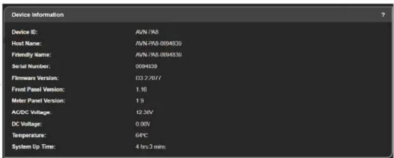
Fig 8-1: Device Information
PTP Clock Information
This section shows the status of the Precision Time Protocol (PTP) clock.

Fig 8-2: PTP Clock Information
Ethernet Network Information
This section shows the current configuration of the ethernet network port. The webserver can also be accessed using this port.

Fig 8-3: Ethernet Network Information
Audio Network Information
This section shows the current configuration of the audio network port. AoIP streams are transmitted and received using this port. The webserver can also be accessed using this port.

Fig 8-4: Audio Network Information
Configuration
There are five sections under the 'Configuration' tab, these are as follows
- Network
- PTP
- Display Settings
- Audio Routing
- GPIO Settings
Each settings page has a 'Submit' button, this is initially greyed out and disabled when the page is loaded. After changes are made to the web of the 'Submit' button is enabled and change to a green colour, pressing the button will then save any changes made to the page. If the user tries to navigate to another webpage when changes have been made an alert by
will be displayed asking the user if they would like to save the change
if the user selects 'OK' the changes are saved before moving to the new in this field a password must be retyped, this is to make sure you didn't page, if 'Cancel' is selected, any changes made are discarded before moving. I accidentally enter your intended password incorrectly. to the new page.
Friendly Name – The friendly name identifies the unit on the network. It is a good idea to assign a user name or location as this is easily recognised by other users. The default friendly name is made from the device ID and the 7-digit product serial number i.e. AVN-PA8-1234567. The friendly name can only contain letters, numbers and hyphens although it cannot start or end with a hyphen.
Password
In order to prevent other users connected to the same network from modifying the configuration of the device it is possible to protect your device with a password. The password may be between 4 and 8 characters long and may only contain numbers and letters. The username when to logging in is always 'admin'.
made Retype Password
In this field a password must be retyped, this is to make sure you didn't very suddenly enter your intended password incorrectly.
Network
The Network page shows the current configuration of the Ethernet and AoIP network ports. The friendly name is also set here.
Removing Password Protection
Password protection can be removed from a device by clearing both the 'Password' and 'Retype Password' fields and clicking submit.
Device Name & Security
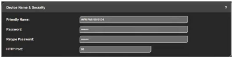
Fig 8-5: Device Name & Security
8 Embedded Web Server
HTTP Port
Address Mode – Each network port has its own independent address mode
The HTTP port number can be set to any integer from '1024' up to and which determines how the port obtains its IP address. When set to including '65535', or to '80' the default value. The value entered determin dynamic, the unit will attempt to acquire an IP address automatically from which port the web server on the device will use. When the port number either a DHCP server or via auto configuration if no DHCP server is found, modified the unit will be restarted automatically. To view the web pages that actual IP address will be shown on the device information page. When a device with a modified port number the port number must be specified static mode is used, the IP address and subnet mask values entered will be the address bar of the web browser after the IP address and separated assigned to the corresponding network port.
colon.
For example, if the HTTP port of a unit is set to '1024' and the IP ad the unit '192.168.0.100' then 'http://192.168.0.100:1024' would need to enter into the address bar of the web browser.
Static IP Address - This is the IP address that will be assigned to the
Corresponding network port when static address mode is selected. It is important to ensure that this IP address is not currently in use on the network. These values are not used when the address mode is dynamic
When the port is set to its default value of '80' a port number does need to be specified when accessing the web server.
Static Subnet Mask - This is the subnet mask that will be used for the corresponding network port when static address mode is selected. These values are not used when the address mode is dynamic.
The web server on the unit is advertised as an Avahi/Bonjour service so
tools like Sonifex Service Discovery or avahi-browse will be able to discoAuto Multicast – When this option is enabled and the address mode of the the address and port number being used by the web server on the unitAoIP port is set to static, the AoIP transmit multicast IP addresses, shown
Network Port Settings
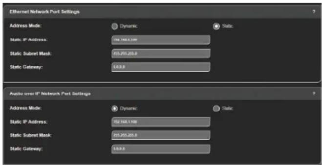
on the Audio Routing Web Page, are automatically configured based on the AoIP port IP address. If the IP address of the AoIP port is changed, the multicast addresses are updated. This simplifies configuration and ensures the multicast addresses are unique on the network.
If any of the network configuration options are changed, the unit will automatically restart to implement the new settings. If the IP address of the network port that is currently being used to access the web server is changed, a new connection will need to be made once the unit has restarted. Otherwise, the new page will be shown automatically once the restart is complete.
Fig 8-6: Network Port Settings
Network Defaults
Friendly Name: AVN-PA8-xxxxxxx
Where xxxxxxx is the product serial number
Ethernet Port:
Address Mode: Static
Static IP Address: 192.168.0.100
Static Subnet Mask: 255.255.255.0
Audio over IP Port:
Address Mode: Static
Static IP Address: 192.168.1.100
Static Subnet Mask: 255.255.255.0
Auto Multicast: Enabled
PTP Profiles Web Page
The PTP Profiles page shows the currently selected PTP profile. It also allows the parameters in each profile to be edited.
PTP Profiles

Fig 8-7: PTP Profiles
Active Profile – There are five PTP profiles available: Default, AES67 Med SMPTE, AES-SMPTE and Custom. This dropdown list selects which of the profiles will be active.
DSCP - The DSCP (or Differentiated Services Code Point) value is used DiffServ to control the precedence of outgoing PTP packets. Network hardware can use this value to ensure PTP data has higher priority over other network traffic. See Table 12 1 - DSCP Names & Their Correspond IP Precedence for more information.
Profile Settings
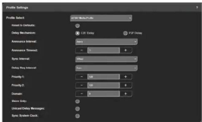
Fig 8-8: Profile Settings
Profile Select – This dropdown list selects the profile to view and change settings. All of the available profiles can be edited.
Reset to Defaults – Selecting this checkbox and pressing the submit button resets the selected profile to the default settings for that profile.
Delay Mechanism – This selects the method for calculating and maintaining the clock synchronisation communication delay between master and slave
devices. Both P2P (Peer to Peer) and E2E (End to End) methods are supported. The best method for a particular installation will depend on the type of network hardware used. If all the switches are known to be IEEE
588 capable, P2P should be used. Otherwise it is best to use E2E.
Announce Interval – This is the rate at which the announce message is sent, one per the selected time. The announce message forms part of the Best
Master Clock Algorithm (BMCA) and contains the properties of the clock
8 Embedded Web Server
which sends it. If a device receives an announce message from a better Unicast Delay Messages – When deselected multicast is used to send delay clock, it will enter the slave state. and delay response messages. When selected delay and delay response
Announce Timeout – This is the time the unit will wait for an announce message and is a multiple of announce intervals. If no announce messageSync System Clock – When this option is selected, the system clock (i.e. the are received within the timeout interval, the unit will assume the role of date and time) of the unit is synchronised with the PTP master.
grandmaster.
PTP Profiles Defaults
Sync Interval - This is the rate at which the sync message is sent, one per the selected time. The sync and follow up messages are sent from the master to the slave to determine the difference in clock frequency. This information is used in conjunction with the network delay to synchronise the clocks.
Delay Request Interval - This defines the rate at which a slave clock sends delay request messages to the master. The delay request message allows a slave device to calculate the network delay from the slave to the master. This option is only valid when using the E2E delay mechanism.
Peer Delay Request Interval - This is the rate at which a device exchanges peer delay measurement messages. This allows each unit to track the network delays between itself and its connected neighbours. This option is only valid when using the P2P delay mechanism.
Priority 1 & Priority 2 – These values define a precedence setting used by the best master clock algorithm when selecting a grandmaster clock. Priority 2 defines a fine tune setting when multiple clock sources have similar ordering criteria.
Domain - This defines the group of PTP devices that the unit will communicate with.
Slave Only – This option limits the unit to being a slave PTP clock only.
Active Profile: Default
DSCP: AF PHB
Default Profile
Delay Mechanism: E2E
Announce Interval: 2 secs
Announce Timeout: 3 secs
Sync Interval: 1 sec
Delay Request Interval: 1 sec
Priority 1: 128
Priority 2: 128
Domain: 0
Slave Only: Disabled
Unicast Delay Messages: Disabled
Sync System Clock: Disabled
AES67 Media Profile
Delay Mechanism: E2E
Announce Interval: 2 secs
Announce Timeout: 3 secs
Sync Interval: 1/8 sec
Delay Request Interval: 1 sec
Priority 1: 128
Priority 2: 128
Embedded Web Server 8
Domain: 0
Slave Only: Disabled
Unicast Delay Messages: Disabled
Sync System Clock: Disabled
SMPTE Profile
Delay Mechanism: E2E
Announce Interval: 1/4 secs
Announce Timeout: 3 secs
Sync Interval: 1/8 sec
Delay Request Interval: 1/8 sec
Domain: 127
Slave Only: Enabled
Unicast Delay Messages: Enabled
Sync System Clock: Disabled
AES-SMPTE Profile
Delay Mechanism: E2E
Announce Interval: 1 sec
Announce Timeout: 3 secs
Sync Interval: 1/8 sec
Delay Request Interval: 1/8 sec
Domain: 0
Slave Only: Enabled
Unicast Delay Messages: Enabled
Sync System Clock: Disabled
Custom Profile
Delay Mechanism: E2E
Announce Interval: 2 secs
Announce Timeout: 3 secs
Sync Interval: 1 sec
Delay Request Interval: 1 sec
Priority 1: 128
Priority 2: 128
Domain: 0
Slave Only: Disabled
Unicast Delay Messages: Disabled
Sync System Clock: Disabled
8 Embedded Web Server
Display Settings
On all devices the 'Front Panel Settings' section should be available, on Click on the '+' and '-' buttons or type in a value, to set the time until the devices with a meter panel the 'Meter Panel Settings' section should also screen saver is activated on the OLED and meter displays (if fitted). This is be available. measured in minutes and can be any whole number from 0 to 60, setting it
The following devices have a metering panel.
AVN-PA8D
AVN-PA8TD
AVN-PD8D
AVN-PD8TD
AVN-PM8D
AVN-PM8TD
Front Panel Settings
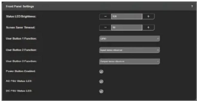
Fig 8-9: Front Panel Settings
Status LED Brightness
Click on the '+' or '-' button, or type in a value, to change the brightness of
the status LEDs on the front panel of the device, the brightness can be Det PSU Status LED
to any value from 0 to 255 with 0 being the dimmest setting and 255 being the brightest. This option enables or disables the DC PSU status LED on the front panel.
Screen Saver Timeout
Click on the '+' and '-' buttons or type in a value, to set the time until the screen saver is activated on the OLED and meter displays (if fitted). This is measured in minutes and can be any whole number from 0 to 60, setting it to 0 disables the timeout.
User Button 'N' Function
This allows the user to perform a function when button 'n' on the front panel is pressed, where 'n' is 1, 2 or 3, the options available are 'None', 'GPIO', 'Input Menu Shortcut' and 'Output Menu Shortcut'.
'None' – Pressing the associated user button does nothing.
'GPIO' – Allows the button to be configured in the 'GPIO Settings' webpage, for example the button could be used to mute and output.
'Input Menu Shortcut' – Allows the user to jump into the 'Input Channel' menu on the OLED display which allows the user to select an input channel to be shown in full-screen mode on the TFT metering display.
'Output Menu Shortcut' – Allows the user to jump into the 'Output
Channel' menu on the OLED display which allows the user to select an input channel to be shown in full-screen mode on the TFT metering display.
Power Button Enabled
This option enables the power button on the front panel of the unit. When enabled, pressing the power button will switch the unit on and off.
AC PSU Status LED
This option enables or disables the AC PSU status LED on the front panel.
Meter Panel Settings
This section is only available on devices with a 'Meter Display' (device ID ends in a 'D')
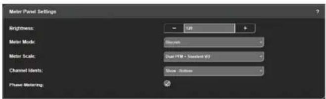
Fig 8-10: Meter Panel Settings
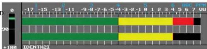
heatmap
| Value | Color | |---|---| | -17 | Black | | -15 | Green | | -13 | Green | | -11 | Green | | -9 | Green | | -8 | Yellow | | -7 | Yellow | | -6 | Yellow | | -5 | Yellow | | -4 | Yellow | | -3 | Yellow | | -2 | Red | | -1 | Yellow | | 0 | Yellow | | 1 | Yellow | | 2 | Yellow | | 3 | Yellow | | 4 | Yellow | | 5 | Black | | 6 | Black | | 7 | Black | | 8 | Black | | 9 | Black | | +180 IDENTX2IFig 8-12: Continuous Meter Mode Image
Meter Scale
Many different types of scale can be selected to display alongside metering, the available options are as follows.
The characteristics in the following tables are true when there is 0dB of input gain. (See Table 8-1 and 8-2 here).
Brightness
Click on the '+' and '-' buttons, or type in a value, to change the brightness of the backlight for the meter displays, the brightness can be set to any value from 0 to 255 with 0 being the dimmest setting and 255 being the brightest.
Meter Mode
This can be set to either 'Discrete' or 'Continuous' and changes the appearance of the meter bar of the meter display.
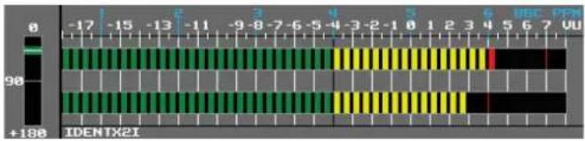
Fig 8-11: Discrete Meter Mode Image
8 Embedded Web Server
Normal Layout
| Meter Characteristics | Scale Range Without Phase Meter | Scale Range with Phase Meter | 0dBFS Reference | Start of Amber Section | Start of Red Section |
| Dual PPM + Standard VU | -8 to +12dBu -2 to +12 dBu | +18dBu 0dBu +8dBu | |||
| EBU PPM -9 to +12 dBu | -7 to +12 dBu +18dBu | 0dBu +8dBu | |||
| BBC PPM -8 to +12 dBu | -5 to +12 dBu +18dBu | 0dBu +8dBu | |||
| Nordic PPM -30 to +12 dBu | -26 to +12 dBu | +18dBu 0dBu +6dBu | |||
| AES Digital PPM | -42 to 0 dBFS | -38 to 0 dBFS | +18dBu | -18dBFS | 0dBFS |
| DIN PPM | -23 to +11 dBu | -19 to +11 dBu | +18dBu | -3dBu | +4dBu |
| German PPM | -32 to +15 dBu | -26 to +15 dBu | +15dBu | -32dBu | +7dBu |
| SMPTE RP.0155 | -42 to 0 dBFS | -38 to 0 dBFS | +18dBu | -20dBFS | 0dBFS |
| Standard VU | -18 to +3 VU | -16 to +3 VU | +18dBu | -4VU | 0VU |
| Extended VU | -16 to +15 VU | -12 to +15 VU | +18dBu | -4VU | 0VU |
Table 8-1: Normal Layout.
Detailed View
| Meter Characteristics | Scale Range Without Phase Meter | Scale Range with Phase Meter | 0dBFS Reference | Start of Amber Section | Start of Red Section |
| Dual PPM + Standard VU | -17 to +12 dBu | -14 to +12 dBu | +18dBu | 0dBu | +8dBu |
| EBU PPM | -17 to +12 dBu | -14 to +12 dBu | +18dBu | 0dBu | +8dBu |
| BBC PPM | -16 to +12 dBu | -13 to +12 dBu | +18dBu | 0dBu | +8dBu |
| Nordic PPM -47 to +12 dBu | -41 to +12 dBu | +18dBu | 0dBu +6dBu | ||
| AES Digital PPM | -59 to 0 dBFS | -53 to 0 dBFS | +18dBu | -18dBFS | 0dBFS |
| DIN PPM | -48 to +11 dBu | -42 to +11 dBu | +18dBu | -3dBu | +4dBu |
| German PPM | -64 to +15 dBu | -58 to +15 dBu | +15dBu | -54dBu | +7dBu |
| SMPTE RP.0155 | -59 to 0 dBFS | -53 to 0 dBFS | +18dBu | -20dBFS | 0dBFS |
| Standard VU | -26 to +3 VU | -23 to +3 VU | +18dBu | -4VU | 0VU |
| Extended VU | -68 to +15 VU | -56 to +15 VU | +18dBu | -4VU | 0VU |
Table 8-2: Detailed View.
Channel Idents
The identities of channels can be displayed either above the metering when 'Show -Top is selected, below the metering when 'Show - Bottom' is selected or hidden by selecting 'Hidden'.
Phase Metering
This shows the phase difference of the signal on the left and right channel of an input of output. Selecting the checkbox enables this functionality. This is unavailable on the inputs of the AVN-PM8D and AVN-PM8TD as they have mono inputs. Phase metering is shown on a scale from +180 to 0.
Audio Routing
On this page inputs, outputs, AoIP streams and routing can all be configured. This is done through the use of pop-up windows and a routing grid.
Add an AoIP Input Stream
Clicking on the plus button next to the 'INPUTS' text and then clicking the button 'Add AoIP Input' brings up a window 'Add New AoIP Input Stream', the window has three tabs 'General', 'AoIP' and 'EQ'. When the window is first loaded the 'AoIP' tab is selected.
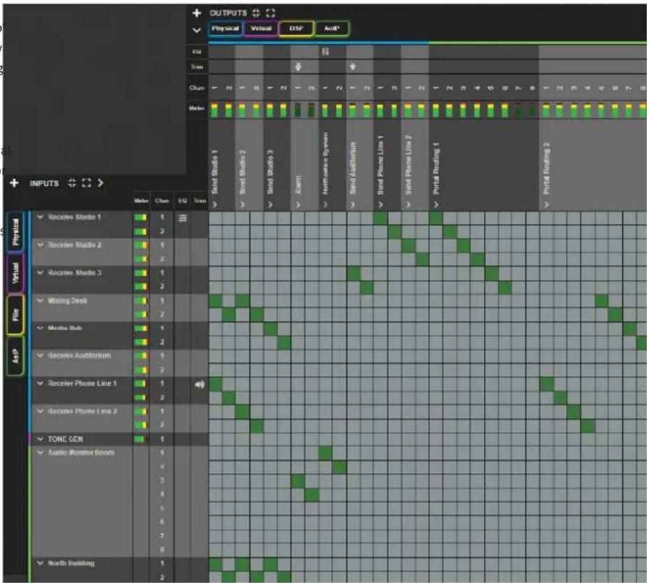
Fig 8-13: Audio Routing Web Page
8 Embedded Web Server
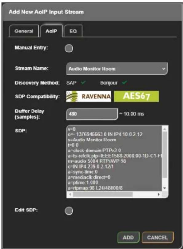
Fig 8-14: AoIP Tab of Add New AoIP Stream Window
AoIP Tab
Automatic Discovery
In the 'AolP' tab, the "Stream Name" drop-down box contains a list of all the streams that have been discovered on the network when a stream is selected in this drop-down, information about the stream is shown. The information shown includes:
- Discovery Method – Streams are discovered using SAP or Avahi/Bonjour. A green tick will be shown to indicate how the selected stream was discovered.
- SDP Compatibility – AES67 and RAVENNA logos are shown here when the SDP of a discovered stream contains the parameters required for each standard. It the logo is not shown, then the SDP that has been discovered does not contain all the necessary parameters.
- SDP – The SDP that was discovered for the selected stream is shown in the SDP box.
- SDP Errors – If there are any errors with the SDP then another textbox will be shown giving details of these.
A 'Buffer Delay' can also be set for the selected stream, this allows for smooth playback of digital streams in a high latency network, the buffer delay is measured in samples and can be entered manually or one of the options 18, 48, 96, 144, 192, 240, 480, or 960 from the drop-down list can be selected.
It is also possible to edit the SDP of a discovered stream (for example to add a parameter that was missing from the SDP which meant that the stream was not recognised as being RAVENNA compatible). This can be done by clicking the "Edit SDP" checkbox which allows the text in the SDP text box to be modified. To add a stream to the grid, click the Add button.
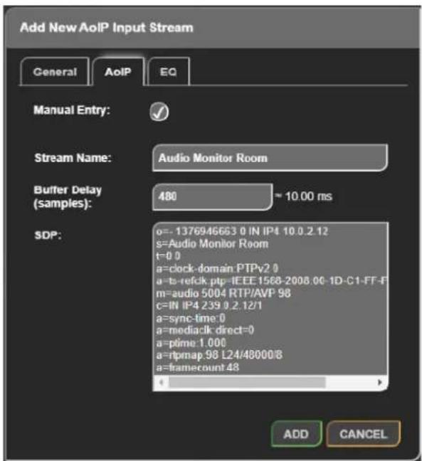
Fig 8-15: AoIP Tab of Add New AoIP Stream Window with Manual Entry Checkbox Selected
Manual Entry
If a particular AoIP stream is not discoverable via SAP or Avahi/Bonjour it is possible to add the SDP manually by selecting the "Manual Entry" checkbox. When selected, the user can enter a custom "Stream Name" an SDP for the custom stream.
As with the discovered streams, a "Buffer delay" can be set before clicking the Add button to add the stream to the grid.
General Tab
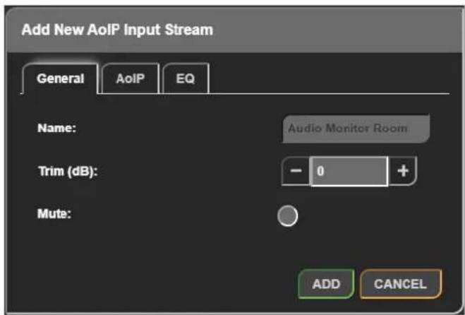
Fig 8-16: General Tab of Add New AoIP Input Stream Window
In the 'General' tab the value in the 'Stream Name' field of the stream you have selected in the 'AoIP' tab is displayed in the 'Name' text field. The trim level of the stream can also be modified by using the plus and minus buttons or typing a value in the text field of the 'Trim' section, the increase or decrease in the level of the stream is measured in decibels (dB) and can be any whole number from -12 to +12. If the trim is adjusted an icon (or 📄) will be shown next to the name of the stream on the grid depending on the trim level set. A stream can be muted by selecting the 'Mute' checkbox before adding it, this is useful if you want to pre-configure a then streams routing. If a stream is muted, a mute icon ( ) will be shown next to the stream name in the grid.
8 Embedded Web Server
EQ Tab
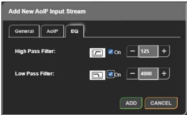
Fig 8-17: EQ Tab of Add New AoIP Input Stream Window
Configuring AoIP Inputs
After adding an AoIP input stream it appears on the audio routing grid. Clicking the name of an AoIP input, located to the left of the routing grid, opens the 'Edit AoIP Input Stream' window, this window is essentially the same as the window that opens up when 'Add AoIP In Stream' is pressed, however there are a couple of extra features under the 'AoIP' tab.
If the stream was added manually, by clicking 'Manual Entry', at the top of the 'AoIP' tab will be a label 'Manual Entry' with a green tick next to it.
An option to edit the SDP of an AoIP input stream is also available, this is done by selecting the 'Edit SDP' checkbox, this then allows the 'SDP' information input field to be edited. There is also a label 'Edited' with a black cross next to it, when the SDP for a stream that was automatically discovered has been edited, the black cross next to the label changes to a green tick.
A 'Remove' button is also available at the bottom of an edit window. When
The last tab available is the 'EQ' tab which allows a high pass filter and pressed the AoIP input stream is removed from the grid.
pass filter to be applied to a stream.
Add an AoIP Output Stream
- The 'High Pass Filter' can be enabled by selecting the 'On' checkbox. This is on the plus button next to the 'OUTPUTS' text and then clicking the removes low frequency components from a signal. The frequency of the button 'Add AoIP Output' brings up a window 'Add New AoIP Output lowest components to be allowed can be set using the '+' and '-' buttons', the window has three tabs 'General', 'AoIP' and 'EQ'. When the or by typing in a value in the input field. window is first loaded the 'General' tab is selected.
- The 'Low Pass Filter' can be enabled by selecting the 'On' checkbox. This removes high frequency components from a signal. The frequency of the highest components to be allowed can be set using the '+' and '-' buttons or by typing in a value in the input field.
- The value in these two fields can be any whole number from 40 to 10000Hz.
- If a filter is set up for a stream, a icon will be shown next to the stream name in the grid.
By pressing the green 'Add' button the stream is then added to the grid.
General Tab
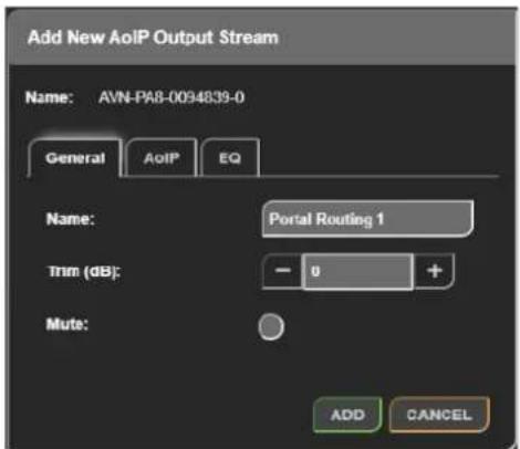
Fig 8-18: General Tab of Add New AoIP Output Stream Window
By default, the 'Name' field has the friendly name of the unit followed hyphen and the stream number, this can be changed by modifying the in the field. The level of the signal being output can be increased or decreased using the value in the 'Trim' field. The value in this field can be modified by pressing the plus and minus buttons or manually entering a value into the input field. The value can be any whole number from -1 +12 and is measured in decibels (dB). If the trim is adjusted icon (
will be shown next to the name of the stream on the grid depend on the trim level set. A stream can be muted by selecting the 'Mute' check before adding it, this is useful if you want to pre-configure a streams routing. If a stream is muted, a mute ion ( ) will be shown next to t stream name in the grid.
AoIP Tab
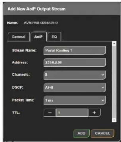
Fig 8-19: AoIP Tab of Add New AoIP Output Stream Window
Stream Name
In the 'AoIP' tab the stream name can again be seen in the 'Stream Name' field. 2 to
or Address
A multicast or unicast IP address can be entered in the 'Address' field. This field cannot be changed when 'Auto Multicast' is enabled within the 'Network' web page.
Channels
The number of channels the AoIP stream consists of can be selected from the 'Channels' dropdown menu this can be set to either 2, 4 or 8, and can be modified later if required.
8 Embedded Web Server
DSCP
The DSCP of the stream can also be set to allow the precedence of the stream packets to be modified. The different values this field can be set is covered in Table 12 1: DSCP Names & Their Corresponding IP Precede
Packet Time
The 'Packet Time' of an AoIP output stream can be changed. The time between packets and the size of the packets both decrease as the value 'Packet Time' decreases. Therefore, decreasing the packet time will result smoother audio streaming on higher latency networks. Not all devices can handle lower packet times, if this is the case, the packet time will need be adjusted in order to be compatible with those devices. This packet time can be set to either 125 μs, 250 μs, 333 μs, 1 ms or 4 ms. The 'Packet Time' can only be set to 4 ms when the number of 'Channels' is set to 2.
TTL
The Time to Live (TTL) option can be set to an integer value from 1 to and is used to limit the time a packet spends on a network.
EQ Tab
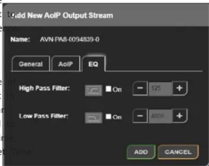
Fig 8-20: EQ Tab of Add New AoIP Output Stream Window
The last tab available is the 'EQ' tab which allows a high pass filter and low pass filter to be applied to a stream.
- The 'High Pass Filter' can be enabled by selecting the 'On' checkbox. This removes low frequency components from a signal the frequency of the lowest components to be allowed can be set using the '+' and '-' buttons or by typing in a value in the input field.
- The 'Low Pass Filter' can be enabled by selecting the 'On' checkbox. This removes high frequency components from a signal the frequency of the highest components to be allowed can be set using the '+' and '-' buttons or by typing in a value in the input field.
- The value in these two fields can be any whole number from 40 to 10000Hz.
- If a filter is set up for a stream, a icon will be shown next to the stream name in the grid.
Embedded Web Server 8
Configuring AoIP Outputs
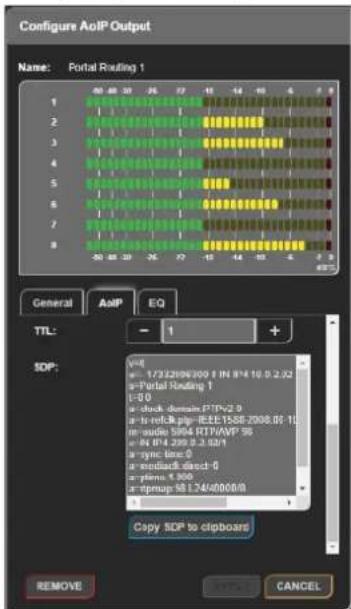
Fig 8-21: AoIP Tab of Configure AoIP Output Window
Clicking the name of an AoIP output stream, located along the top of the routing grid, opens a window entitled 'Configure AoIP Output', this window is essentially the same as the window that opens up when 'Add AoIP OutStream' is pressed, with a few exceptions:
• Detailed metering is shown at the top of the window.
- The SDP of the AoIP output stream can be found in the 'AoIP' tab a button is available to copy the SDP to the clipboard.
- A 'Remove' button is also available at the bottom of an edit window. When pressed, it removes the AoIP output stream from the device.
Add a File Playback Input
A file playback input allows the user to play audio files uploaded to the unit. The file playback inputs support WAV type files with a sample rate of 48 kH. To add a file playback input first the add (+) button is pressed, then the 'Add File Playback Input' button is pressed. The 'Add New File Playback Input' window will open with the 'Files' tab selected.
Files Tab
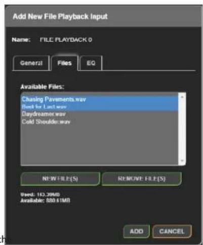
8-22: Files Tab of Add New File Playback Input Window
The 'Files' tab displays a list of available files, to add new files to this list of 'New File(s)' and select audio files from your computer to upload to the unit. Whilst the upload is in progress a status bar is shown, once the upload is complete the new files can be selected for playback. To remove a file from unit, click on the files name and click 'Remove File(s)'. Multiple files can be selected at the same time using the 'Shift' and 'Ctrl' keys. Underneath the list of files, the amount of used and available space is shown.
8 Embedded Web Server
General Tab
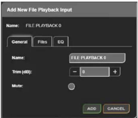
Fig 8-23: General Tab of Add New File Playback Input Window
EQ Tab
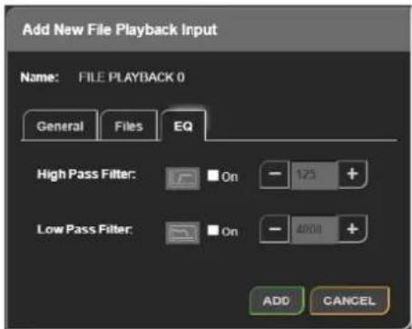
Fig 8-24: EQ Tab of Add New File Playback Input Window
The last tab available is the 'EQ' tab which allows a high pass filter and low In the 'General' tab the name of the file playback input can be changed pass filter to be applied to an input.
modifying the value in the 'Name' field. The trim level of the file playback input can also be modified by using the plus and minus buttons or typing value in the text field of the 'Trim' section, the increase or decrease in the level of the input is measured in decibels (dB) and can be any whole number from -12 to +12. If the trim is adjusted and (icon) or ) will be shown next to the name of the input on the grid depending on the trim level set. An input can be muted by selecting the 'Mute' checkbox before adding it, this is useful if you want to pre-configure an inputs routing. If an input is muted, a mute icon() will be shown next to the input name in the grid. The 'High Pass Filter' can be enabled by selecting the 'On' checkbox. This a removes low frequency components from a signal. The frequency of the lowest components to be allowed can be set using the plus and minus buttons or by typing in a value in the input field. The 'Low Pass Filter' can be enabled by selecting the 'On' checkbox. This removes high frequency components from a signal. The frequency of the highest components to be allowed can be set using the plus and minus buttons or by typing in a value in the input field. The value in these two fields can be any whole number from 40 to 10000Hz
- If a filter is set up for an input, an EQcon() will be shown next to the input name in the grid.
By pressing the green 'Add' button the input is then added to the grid.
Configuring File Playback Inputs
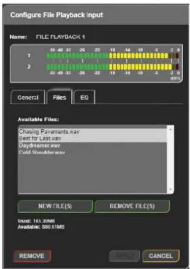
Fig 8-25: Files Tab of Configure File Playback Input Window
Clicking on the name of a file playback input opens the configuration window for that input. This is essentially the same as the window that displayed when adding a file playback input with a few exceptions:
- Detailed metering is displayed at the top of the window.
- A remove button is available and will remove the file playback input the audio routing grid.
Configuring Physical Inputs
General Tab
All Devices
Clicking the name of a physical input, opens a 'Configure Physical Input' window, this window contains two tabs 'General' and 'EQ'. The window opens with the 'General' tab selected. The window has two buttons at the bottom 'Save' and 'Cancel', pressing 'Save' submits the current configuration, whereas selecting 'Cancel' discards changes. Pressing either button causes the window to close. The options available in the 'General' tab vary depending on which device from the AVN Portal series is used. The following options are present on all Portal types:
- Name
- Trim (dB)
- Mute
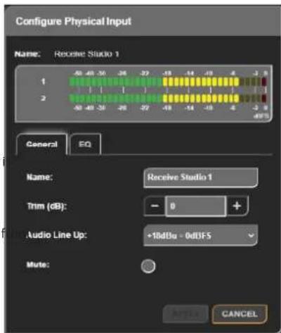
Fig 8-26: General Tab of Configure Physical Input Window (AVN-PA8)
8 Embedded Web Server
The window for an AVN-PA8 (Analogue Inputs and Outputs) is shown in ANN-PM8/T/D
8-26: General Tab of Configure Physical Input Window (AVN-PA8).
In the 'General' tab the name of the input can be changed by modifying value in the 'Name' field. The trim level of the file playback input can be modified by using the plus and minus buttons or typing a value in the text field of the 'Trim' section, the increase or decrease in the level of input is measured in decibels (dB) and can be any whole number from to +12. If the trim is adjusted an icon (air) will be shown next to the name of the input on the grid depending on the trim level set. An input be muted by selecting the 'Mute' checkbox before adding it, this is useful you want to pre-configure an inputs routing. If an input is muted, a mut icon (air) will be shown next to the input name in the grid. The detailed metering for that input's channels can also be seen, this shows the level the audio in dBFS.
AVN-PA8/T/D
As seen in Fig 8-26: General Tab of Configure Physical Input Window (AV PA8) AVN-PA8 devices also have an audio line up configuration option using the 'Audio Line Up' dropdown menu. The line-up level can be set to determine the analogue audio level that is equal to the 0 dBFS full scale digital value. This can be set to either 15, 18, 20, 22, or 24 dBu. The a line-up level will depend on the minimum and maximum audio levels that need to be provided, this will vary depending on the standard used geographically.
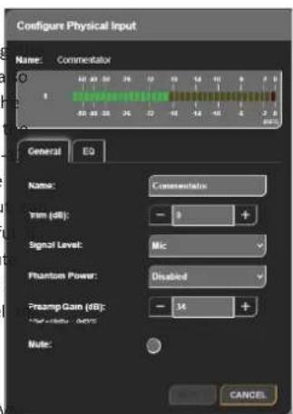
Fig 8-27: General Tab of Configure Physical Input Window (AVN-PM8) - Mic Level
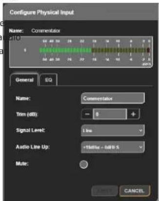
Fig 8-28: General Tab of Configure Physical Input Window (AVN-PM8) - Line Level
As seen in Fig 8-27: General Tab of Configure Physical Input Window (AVN-N-PD8/T/D)
PM8) - Mic Level and Fig 8-28: General Tab of Configure Physical Input Window (AVN-PM8) - Line Level AVN-PM8 devices also have the following options available when configuring an input.
- Signal Level
- Phantom Power
- Preamp Gain (dB)
- Audio Line Up
The 'Signal Level' can be set to either 'Mic' or 'Line'. Selecting 'Mic' displays the options for 'Phantom Power' and 'Preamp Gain' whereas selecting 'Line' displays the 'Audio Line Up' option.
When an input is set to mic level a microphone icon ( ) will be shown to the input name. Each of the devices inputs supports 'Phantom Power this can be enabled or disabled using the dropdown menu. When Phant
power is enabled a +48V DC supply is provided to the microphone, son microphones require this to power any active electronic circuitry they contain. When phantom power is enabled, the microphone icon will be coloured green 🎨).
The user can add from 0 to 60 dB of gain to the microphone input by pressing the plus and minus buttons or manually entering a value into the 'Preamp Gain' input field.
The line-up level can be set under the 'Audio Line Up' dropdown menu. determines the analogue audio level that is equal the 0dBFS full scale value. This can be set to either 15, 18, 20, 22, or 24 dBu. The audio line level will depend on the minimum and maximum audio levels that need be provided, this will vary depending on the standard used geographically
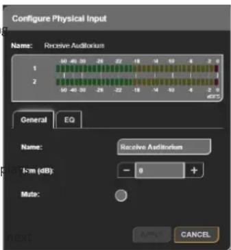
Fig 8-29: General Tab of Configure Physical Input Window (AVN-PD8)
As seen in Fig 8-29: General Tab of Configure Physical Input Window (AVN-PD8) AVN-PD8 devices have no extra settings to configure.
EQ Tab
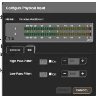
Fig 8-30: EQ Tab of Configure Physical Input Window
8 Embedded Web Server
All devices have an 'EQ' tab which allows a high pass filter and low pass filter to be applied to an input.
- The 'High Pass Filter' can be enabled by selecting the 'On' checkbox. It removes low frequency components from a signal. The frequency of the lowest components to be allowed can be set using the plus and minus buttons or by typing in a value in the input field.
- The 'Low Pass Filter' can be enabled by selecting the 'On' checkbox. The removes high frequency components from a signal. The frequency of the highest components to be allowed can be set using the plus and min buttons or by typing in a value in the input field.
- The value in these two fields can be any whole number from 40 to 10000Hz.
- If a filter is set up for an input, an EIcon ( ) will be shown next to input name in the grid.
Configuring Physical Outputs
General Tab
All Devices
Clicking the name of a physical output, located to the top of the routing grid, opens a window entitled 'Configure Physical Output', this window contains two tabs 'General' and 'EQ'. The window opens with the 'General tab selected; the tab that is currently selected has a blue background. The window has two buttons at the bottom 'Save' and 'Cancel', pressing 'Save' submits the current configuration, whereas selecting 'Cancel' discards changes. Pressing either button causes the window to close. The options available in the 'General' tab vary depending on which device from the Portal series is used. Some options remain available regardless of the device however, these are the following options.
- Name
- Trim (dB)
- Mute
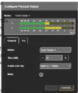
Fig 8-31: General Tab of Configure Physical Output Window (AVN-PA8)
The window for an AVN-PA8 (Analogue Inputs and Outputs) is shown in Fig 8-31: General Tab of Configure Physical Output Window (AVN-PA8).
In the 'General' tab the name of the output can be changed by modifying the value in the 'Name' field. The trim level of the output can also be modified by using the plus and minus buttons or typing a value in the text field of the 'Trim' section, the increase or decrease in the level of the output is measured in decibels (dB) and can be any whole number from -12 to +12. If the trim is adjusted an icon (or ) will be shown next to the name of the output on the grid depending on the trim level set. An output can be muted by selecting the 'Mute' checkbox before adding it, this is useful if you want to pre-configure an outputs routing. If a n output is muted, a mute icon( ) will be shown next to the output's name in the grid. The detailed metering for that output's channels can also be seen, this shows the level of the audio in dBFS.
AVN-PA8/T/D and AVN-PM8/T/D
The AVN-PA8 and AVN-PM8 both have analogue line level output and v have the same options as shown in Fig 8-31: General Tab of Configure Physical Output Window (AVN-PA8).
The devices have an audio line up configuration option using the 'Audio Up' dropdown menu. The line-up level can be set to determine the analogue audio level that is equal to the 0 dBFS full scale digital value. can be set to either 15, 18, 20, 22, or 24 dBu. The audio line-up level depend on the minimum and maximum audio levels that need to be provided, this will vary depending on the standard used geographically.
AVN-PD8/T/D
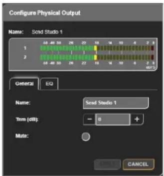
Fig 8-32: General Tab of Configure Physical Output Window (AVN-PD8)
As seen in Fig 8-32: General Tab of Configure Physical Output Window (AVN-PD8) there are no extra options to configure on the AVN-PD8.
EQ Tab
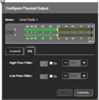
Fig 8-33: EQ Tab of Configure Physical Output Window
All devices have an 'EQ' tab which allows a high pass filter and low pass filter to be applied to an output.
- The 'High Pass Filter' can be enabled by selecting the 'On' checkbox. This removes low frequency components from a signal. The frequency of the lowest components to be allowed can be set using the plus and minus buttons or by typing in a value in the input field.
- The 'Low Pass Filter' can be enabled by selecting the 'On' checkbox. This removes high frequency components from a signal. The frequency of the highest components to be allowed can be set using the plus and minus buttons or by typing in a value in the input field.
- The value in these two fields can be any whole number from 40 to 10000Hz.
- If a filter is set up for an output, an EQIcon ( ) will be shown next to t output name in the grid.
8 Embedded Web Server
Configuring the Tone Generator
General Tab
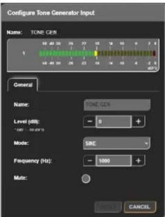
Fig 8-34: General Tab of Configure Tone Generator Input Window
A tone generator is provided on all devices to allow the user to generate various signals, detailed metering for the tone generator can be seen in configuration window. The tone generator cannot be renamed.
The 'Level' field allows the signal level to be adjusted. When 0 dB of g applied the output is at -18 dBFS. The gain can be set to any integer v from -80 dB up to 10 dB.
Three different modes are available for the tone generator and can be selected from the 'Mode' dropdown menu, these are:
- Sine – In this mode a frequency is entered.
- Saw – In this mode a frequency is entered.
- DTMF – In Dual-Tone Multi-Frequency signalling mode a DTMF digit is selected.
The 'Frequency' field is adjusted in steps of 100 Hz and can be set to a value from 100 Hz up to 10 kHz.
| 1209 Hz 1336 Hz 1477 Hz 1633 Hz | |||||
| 697 Hz | 1 2 3 A | ||||
| 770 Hz | 4 5 6 B | ||||
| 852 Hz | 7 8 9 C | ||||
| 941 Hz | * 0 # D | ||||
Table 8-3: DTMF Digits and Their Corresponding Frequencies
The 'DTMF Digit' dropdown menu allows a DTMF digit to be selected, each DTMF digit produces a combination of two tones which can then be detected. The tones generated are shown in Table 8 3: DTMF Digits and Their Corresponding Frequencies.
The tone generator can be muted by selecting the 'Mute' checkbox before adding it, this is useful if you want to pre-configure the tone generators routing. If the tone generator is muted, a mute button ( ) will be shown next to the input name in the grid.
Adding A DSP Function
DSP functions allow the user to detect events in received audio and trigger GPIO. To add a DSP function to the grid, first the add (+) button is pressed, then the 'Add DSP Function' button is pressed. The 'Add New DSP Virtual Output' window will open with the 'General' tab selected.
General Tab
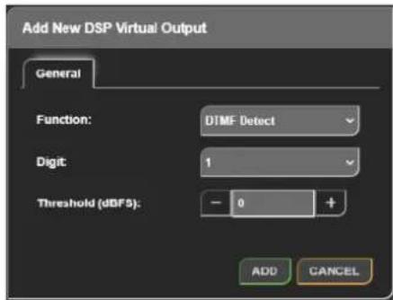
Fig 8-35: General Tab of Add New DSP Virtual Output Window
The 'Function' dropdown menu allows the DSP function to be selected, the moment the only option available is the 'DTMF Detect' option, this allows DTMF digits to be detected.
The 'Digit' field is displayed when the function is set to 'DTMF Detect', of the digits corresponds to two frequencies the two frequencies for each digit can be seen in Table 8 3: DTMF Digits and Their Corresponding Frequencies.
The 'Threshold' sets the minimum level the input signal must be to trigger DTMF detect.
Configuring DSP Outputs
General Tab
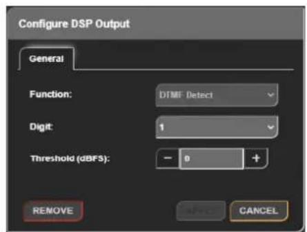
ftg 8-36: General Tab of Configure DSP Output Window
Clicking on the name of a DSP output opens the 'Configure DSP Output' window. This has the same options as when adding a DSP output however that function cannot be changed and a remove button is now available, clicking on the remove button removes the DSP output.
Collapse Inputs/Outputs
When the 'Collapse' button() next to the 'INPUTS' or 'OUTPUTS' text is pressed the inputs/outputs on the routing grid are minimised. Each channel is hidden and instead, an overview of the routings is shown. If any channels from an input stream are routed to any channels of an output stream, the corresponding grid box will be coloured in light green. There is also the option to minimise individual inputs and outputs by pressing the downwards pointing arrow next to the inputs/outputs name.
8 Embedded Web Server
Expand Inputs/Outputs
When the 'Expand' button() next to the 'INPUTS or 'OUTPUTS' text is pressed the inputs/outputs of the routing grid are maximised and their channels are displayed. The boxes for each routing are shown in a darker green when maximised. There is also option to maximise individual inputs and outputs by pressing the sideways pointing arrow next to the inputs/outputs name.
Filtering Inputs/Outputs
Inputs and outputs can be filtered depending on their type allowing the user to focus on only the inputs and outputs they are interested in. Inputs of be filtered based on whether they are 'AoIP', 'File Virtual', or 'Physical' inputs. Outputs can also be filtered based on whether they are 'AoIP', 'DSP', 'Virtual', or 'Physical' outputs. Filtering is performed by clicking on the corresponding buttons to the level of the inputs list and above the outputs list. An example of filtering is shown in Fig 8-37: Filtered Routing Grid, here the user is only interest in the playback inputs and the AoIP outputs.
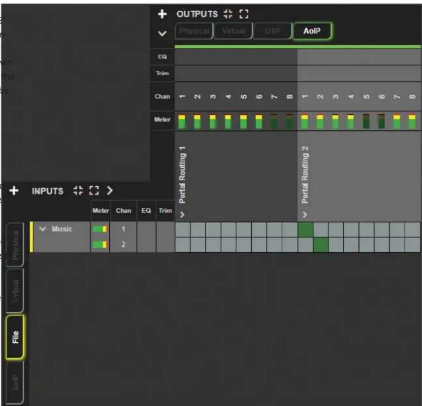
Fig 8-37: Filtered Routing Grid
Show/Hide Input/Output Status Icons
The various status icons on the input and output lists can be show and hidden by pressing the buttons highlight in Fig 8-38: Show or Hide Status Icons, in this image the status icons are shown for the input section and hidden for the output section.
On AVN-PM8/T/D devices a mic/line status icon is displayed. When in mic mode the mic icon (is displayed. When phantom power is enabled, the microphone icon will be coloured green ( ). In line mode no icon is shown.
On AVN-PD8/T/D devices a digital lock status icon is displayed. When a lock has not been obtained a red icon ( ) is displayed. When a lock has been obtained a green icon ( ) is displayed
Routing
Clicking on a box in line with an input/output when that input/output is minimised will maximise that input/output, this then allows the routing of individual channels between that input/output. Routing is achieved by clicking on a box which is in line with an input/output channel, this will cause the audio from the input channel to be routed to the selected output channel. When an input/output channel is routed, the corresponding box will become a dark green colour, clicking on the box when it this dark green colour will open up another window entitled 'Configure Connection'. If the user holds down the 'Ctrl' key and clicks on a
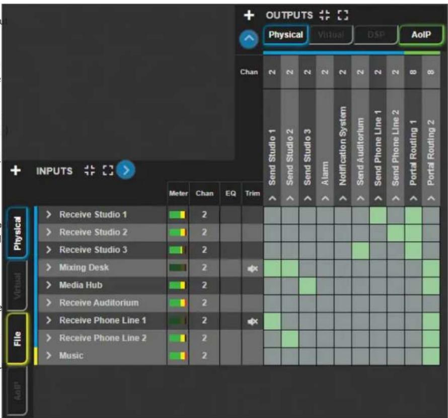
Fig 8-38: Show or Hide Status Icons
8 Embedded Web Server
dark green box, the routing is deleted without having to use the 'Configure' OPIO Settings
Connection" window.
Configuring Connection
General Tab
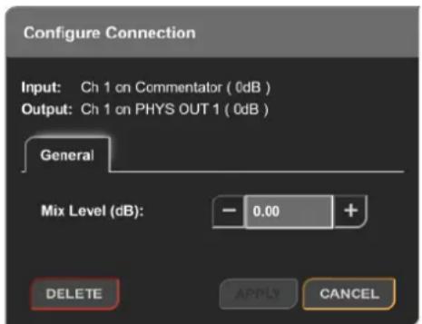
Fig 8-39: General Tab of Configure Connection Window
On the 'GPIO Settings' webpage an overview of connections between logical inputs and logical outputs can be seen, this web page allows the device to be configured to perform actions when a particular event or set of events occurs.
On the input side we have the following options;
- Physical GPI
- Virtual GPI
- Cough GPI
- Events
- User buttons
On the output side we have these options instead;
- Physical GPO
- Virtual GPO
- Events
- User LEDs
- Relays
The 'Configure Connection' window lists the connected input and output An example scenario of when these logical connections might be useful is channels next to the labels 'Input' and 'Output'. The 'General' tab provides follows:
an option to adjust the level of the audio going through this connection, this is done by entering a value into the 'Mix Level' input field or by cl the plus and minus buttons either side of this, the value is measured in and can be any integer value from -100dB to +10dB. At the bottom of window are the options to 'Save' and 'Cancel' changes made to the connection configuration and the option to 'Delete' the connection, this removes the routing between the input and output channel.
In a particular setup the user would like to mute all the physical outputs clicking when a user button is pressed, the corresponding user button's LED should also illuminate when it is active. First, they set the 'User Button 1 Function' to 'GPIO' within the 'Display Settings' web page. Next, they add the GPIO inputs, 'User Button 1' is added as an input. They then add the GPIO outputs, the 'Mute Physical Output' event is added for each of the physical outputs and 'User LED 1' is also added. They then click on the squares
Embedded Web Server 8
between inputs and outputs on the routing grid to create connections. N when 'User Button 1' is pressed all physical outputs will be muted and user button's LED will be illuminated. The results are shown in Fig 8-40: GPIO Routing Example.
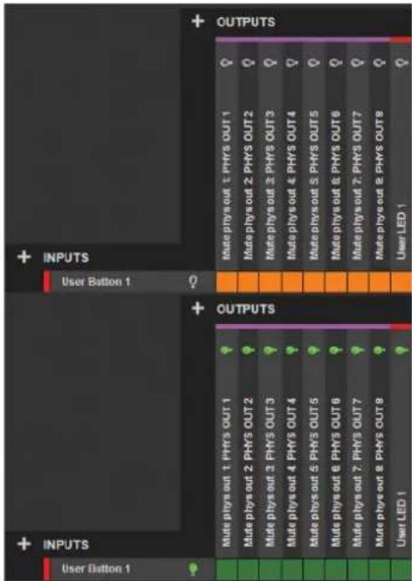
Fig 8-40: GPIO Routing Example
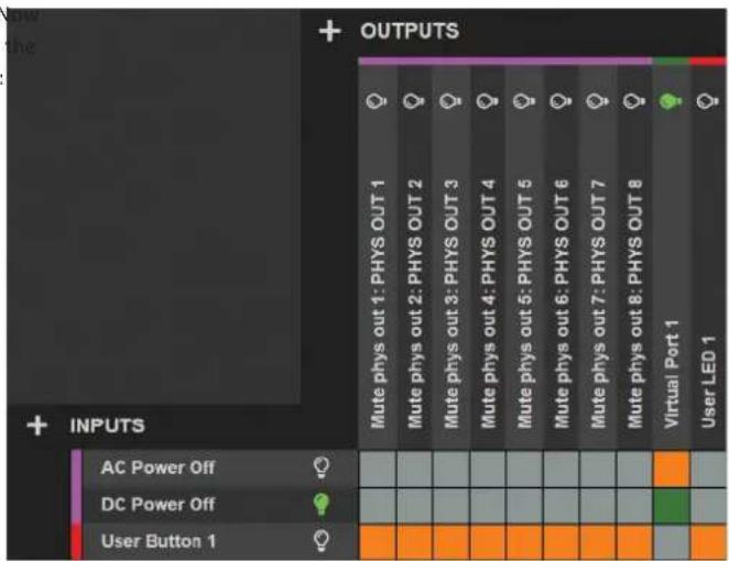
Fig 8-41: GPIO Routing Example 2
Another example is shown in Fig 8-41: GPIO Routing Example 2. On the left-hand side of the routing grid the inputs are shown, these can be events, physical GPI, virtual GPI, cough GPI, or user buttons. Above the routing grid the outputs are shown, these can be events, physical GPO, virtual GPO, user LEDs, or relays.
When first started the device will have no inputs or outputs setup, to add an input or an output to the grid click on the 'Add Input' and 'Add Output' buttons. After adding inputs and outputs to the GPIO grid they can then be routed to each other. Routings in green are active routings and routings in orange are inactive routings.
8 Embedded Web Server
In Fig 8-41: GPIO Routing Example 2, the 'DC Power Off' event is activeType
the lightbulb is green, this then means the routing between 'DC Power Offe type drop-down menu allows the user to configure how the input will and 'Virtual Port 1' becomes active as shown by the green box, finally voperate, the options available are described below.
see the lightbulb on 'Virtual Port 1' is green which shows that the virtual
port is active.
Add Input
Clicking on the button plus button (+) next to the 'INPUTS' text brings up a window with the title 'Add Input' the window has one tab 'General'. At the
bottom of this window are the 'Add' and 'Cancel' buttons. Pressing 'Add' Available Ports
will add the input to the grid. Pressing 'Cancel' at any time will close the Input Mode
window without making any changes.
General Tab
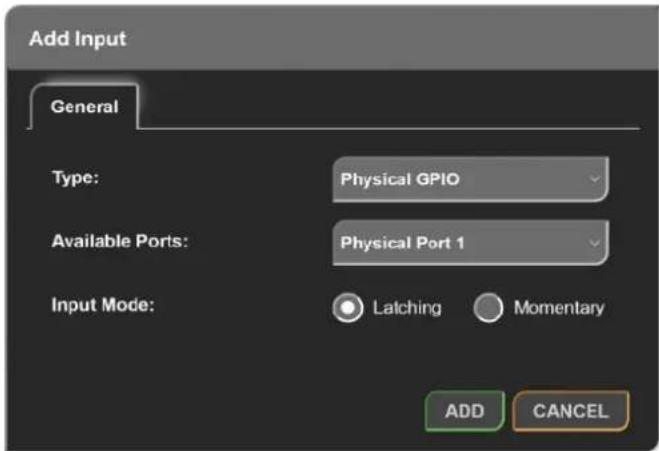
Fig 8-42: General Tab of Add Input Window (GPIO Settings)
Virtual GPIO
Allows a virtual general-purpose input to be created using a source from the network, this can then be as a trigger for an output.
When selected the following options are also displayed:
• Available Ports
- vGPIO Source
Cough
Allows a cough input to be created this cough port can be activated by connecting an AVN-HA1 or AVN-HD1 to an output connection of the portal, this can then be used as a trigger for an output.
When selected the following options are also displayed:
• Available Ports
Event
Allows an input event to be selected which will then cause an output to be triggered, for example an input event could be set when DC power is lost.
When selected the following options are also displayed:
• Available Events
Embedded Web Server 8
User Button
Allows a user button on the front panel of the device to be setup to an output, note that the user button will only work as an input if it as a 'GPIO' within the 'Front Panel Settings' section of the 'Display Se web page.
When selected the following options are also displayed:
• Available Buttons
Available Ports
This drop-down menu allows the user to select which of the available physical ports or virtual ports to setup, this is dependent on the type port selected.
There are ten physical ports available and ten virtual ports available.
Input Mode (Physical GPI only)
The input mode can be set to either 'Momentary' or 'Latching'.
Momentary
When the input mode is set to 'Momentary', the input function is enabling only whilst the input is active.
Latching
When the input mode is set to 'Latching', making the input active brief will toggle whether the input function is enabled or disabled.
vGPIO Source (Virtual GPI only)
The 'vGPIO Source' drop-down window allows the user to select a virtual general-purpose output port from another device that is available on the network and use that to set the state of the virtual input
Available Events
This drop-down menu allows an event to be selected that can then be used as an input to drive the state of another output the list of options are as follows:
Eth Link Down
Aggive when no connection is available via the ethernet network port on that device.
AoIP Link Down
Active when no connection is available via the AoIP network port on the device.
AC Power Off
Active when the status of the AC port is in fault condition (red AC status LED).
DC Power Off
Active when the status of the DC port is in fault condition (red DC status LED).
PTP Sync Lost
Active when the connection to the PTP master is lost.
Digital Lock Lost n (AVN-PD8 Only)
Active when no digital input signal is available on the physical digital input selected.
DSP Function n - x
Active when the DSP function is triggered. The DSP function number is given by 'n' and the type of DSP function is given by 'x'. The function types available are:
None
No function.
eDTMF Detect
Detects Dual-Tone Multi-Frequency signalling digits, this is setup in the audio routing webpage see 'Adding A DSP Function' for more information.
8 Embedded Web Server
Available Buttons
The 'Available Buttons' drop-down menu allows the user to select which Aifows a general-purpose output on the rear panel of the device to be the available user buttons to setup, there are 3 user buttons available enabled when any of the inputs routed to this output are active. the AVN-Portal, these can be found on the front panel of the device.
Add Output
Clicking on the plus button (+) next to the 'OUTPUTS' text brings up a window with the title 'Add Output' the window has one tab 'General'.
the bottom of this window are the 'Add' and 'Cancel' buttons. Pressing 'Add' will add the output to the GPIO grid. Pressing 'Cancel' at any time close the window without making any changes.
General Tab
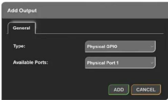
Fig 8-43: General Tab of Add Output Window (GPIO Settings)
Type
The type drop-down menu allows the user to configure how the output will operate, the options available are described below.
Physical GPIO
Allows a general-purpose output on the rear panel of the device to be enabled when any of the inputs routed to this output are active.
When selected the following options are also displayed:
• Available Ports
Virtual GPIO
Creates a virtual general-purpose output on the network, this virtual general-purpose output becomes active when any of the inputs routed to this output are active.
When selected the following options are also displayed:
• Available Ports
Event
Allows an event to be activated when any of the inputs routed to this output are active.
When selected the following options are also displayed:
• Available Events
User LED
Allows the user LED to be toggled between its on colour and its off colour, the on colour is displayed when any of the inputs routed to this output are active, note that the user LED will only work as an output if it is set up as a 'GPIO' within the 'Front Panel Settings' section of the 'Display Settings' web page.
When selected the following options are also displayed:
• Available LEDs
Relay
Allows the relay available on the 'GPIO' connector, to be toggled on and when any of the inputs routed to this output are activated.
When selected the following options are also displayed:
• Available Relays
Available Ports
This drop-down menu allows the user to select which of the available physical ports or virtual ports to setup, this is dependent on the type port selected.
There are ten physical ports available and ten virtual ports available.
Available Events
This drop-down menu allows the event to be triggered when any input routed to this output is active, the list of options are as follows.
Mute Physical Input n: x
Mute the audio on physical input 'n' with name 'x'.
Mute Physical Output n: x
Mute the audio on physical output 'n' with name 'x'.
Mute Tone Generator n: x
Mute the tone generator 'n' with name 'x'.
Mute File Playback Input: x
Mute the file playback input with name 'x'.
Mute AoIP Input n: x
Mute the audio on AoIP output 'n' with name 'x'.
Mute AoIP Output n: x
dMute the audio on AoIP output 'n' with name 'x'.
Stop AoIP Output n: x
Stop AoIP output 'n' with name 'x' completely, this takes down the AoIP output stream so that no audio packets are sent at all as opposed to mute which still sends packets but with no audio in.
Available LEDs
The 'Available LEDs' drop-down menu allows the user to select which of the available user LEDs to setup, there are 3 LED's available on the AVN-Portal, these can be found on the front panel of the device.
Available Relays
The 'Available Relays' drop-down menu allows the user to select which of the available relays on the device is to be setup as an output, there is one relay available on an AVN-Portal.
Routing Grid
The routing grid uses coloured routing squares to show the status of a routing within the grid.
Creating Routings
Normal un-routed squares will be displayed in grey ( ), this represents a potential connection between an input and output that has not yet been routed but is allowed to be, when one of these squares is hovered over the square changes to a darker grey colour ( ). In conjunction with this a series of black squares ( ) in line with that square appear, with the input and output labels also being highlighted in black.
8 Embedded Web Server
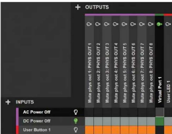
Fig 8-44: Potential GPIO Routing
Clicking on the square then causes a routing to be made between that and output. In the example above clicking would connect the input 'AC Power Off' event to the output 'Virtual Port 1'.
A routed inactive connection is displayed using an orange square ( ), where as an active connection is displayed using a dark green square ( When a connection is active the output connected will become active.
Lightbulbs
Alongside inputs and outputs on the grid are light-bulb symbols, these are normally a dark grey colour ( ) but become green ( ) when the input of output is activated.
Quick Delete
Routing can also be quickly removed without entering the 'Configure Connection' window for each routing. Instead, the user can hold 'Ctrl' on the keyboard and hover over a routing, a red square ( ) is displayed.
This shows that the routing can be deleted. In order to delete the routing, click on the routing whilst it is red.
Non-routable Squares
If an input can't be routed to an output a grey square ( ) is shown and clicking on the square does nothing. Upon hovering over these non-routable squares, the cursor is changed to a 'not-allowed' type cursor ( ).
Configuring Connection
The configure connection window is displayed when a routing is clicked. At the top of the window the input and output being configured is displayed at the bottom of the window the 'Delete', 'Apply', and 'Cancel' buttons are displayed, pressing the 'Delete' button will remove the routing, pressing the 'Apply' button will apply any changes, and pressing the 'Cancel' button will close the window without applying any changes.
General Tab
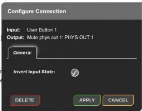
Fig 8-45: General Tab of Configure Connection Window (GPIO Settings)
Invert Input State
This option inverts the input state, this means that if the input is inact the output routing will be active and if the input is active the routing become inactive. For example, if the connection between 'User Button' and the event 'Mute Physical Output 1' is inverted, the output will be muted when the user button is not active and will be unmuted when button is activated.
SNMP Settings
The SNMP settings web page allows the configuration of SNMP message this is used to send traps to an SNMP master which can then perform such as sending an email.
The SNMP master can also get and set certain parameters of the unit.
Download Sonifex MIB Files

Fig 8-46: Download Sonifex MIB Files
The MIB files for this unit can be downloaded and then imported by the SNMP master. Two files 'SONIFEX-MIB' and 'SONIFEX-GPIO-MIB' are used the SNMP master to decode messages received over SNMP.
SNMP Settings
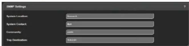
Fig 8-47: SNMP Settings
This section is used to setup the SNMP configuration.
System Location
The system location is used to specify the physical location of the unit this will be set to any value which between 0 and 20 characters in length. The 1'system location can be accessed via SNMP using the OID 1.3.6.1.2.1.1.6 (sysLocation).
the
System Contact
The system contact is used to specify the user of the device this may be set to any value which between 0 and 100 characters in length. The system contact can be accessed via SNMP using the OID 1.3.6.1.2.1.1.4
'sysContact). tasks
Community
The SNMP community string is used as a form of security, if the string is set to 'public' any SNMP master on the network may query the device. If the community string is set to anything else the SNMP master will need to send this community string along with any SNMP requests in order to acquire the requested information otherwise the request will be denied. This may be set to any value which is between 0 and 20 characters long.
Trap Destination
The trap destination is the IP address of the SNMP master, this allows the device to send SNMP trap messages to the SNMP master containing information about the devices current state, for example a SNMP trap message is sent when the state of a GPI is changed along with information about that GPI such as the GPI number and its current state.
Disabling SNMP Trap Messages
To prevent SNMP trap messages being sent the 'Trap Destination' field can be cleared and the form submitted.
9 Front Panel System Menu
System
The system web page can be used for the following:
- Updating the unit.
- Saving and loading configuration files.
- Retrieving the unit's system logs.
- Rebooting and resetting the unit.
Update Firmware
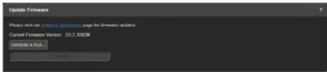
Fig 8-48: Update Firmware
has a default name consisting of the device ID followed by an underscore and then the friendly name. It is a good idea to save the configuration settings of all units on the network once they have been setup as this provides a quick and easy way of returning the units to a known working condition.
Load Configuration from A File

Fig 8-50: Load Configuration from A File
A configuration can be restored from a previously saved configuration file. First click 'Choose A File' and select the configuration file. The current
In this section the current firmware version on the connected unit is showwork settings can be changed to those in the configuration file, this is New versions of firmware will be released as new features are added, and one by selecting the 'Overwrite Network Settings' checkbox. Finally, the when any bug fixes are completed, click on the software downloads link 'load Config' button is clicked and the unit will reboot. Once the unit has visit the firmware downloads webpage of the Sonifex website. If an update rebooted the configuration will match that of the configuration file. If the is available for your unit you can download it as a zipped archive file, network settings are left unchanged the devices webpage will automatically will need to extract the 'SWU' file from the archive, this can be done in reload, otherwise the new address will need to be entered into the web Windows by right-clicking the archive and selecting extract all. browser.
Clicking 'choose a file' will allow the 'SWU' file to be selected, the 'Update' Save System Log to A File
button can then be clicked and the unit will then reboot and the new firmware will be loaded.
Save Configuration to A File

Fig 8-49: Save Configuration to A File

Fig 8-51: Save System Log to A File
An internal log records events and errors. The current log can be retrieved from the device by clicking 'Save Log'. If there have been no process crashes the current log is saved and is a single text file. Otherwise, multiple logs will be stored together in a 'TAR' archive file. This archive can be sent to Sonifex file.
The current configuration of the unit can be saved as a 'JSON' file, this file is stored together in a 'TArt archive file. The current file can be saved and uploaded to the unit at a later point. The downloaded file
Reboot or Factory Reset

Fig 8-52: Reboot or Factory Reset
The unit can be rebooted using the 'Reboot' button, a quick reboot can Fig 8-54: Update Firmware
often fix any issues with the unit, after rebooting the webpage will automatically reload. The 'Factory Reset' button restores the unit to factory settings, restoring the factory settings will also cause the unit to reboot
Click "CHOOSE A FILE" and select the current version for the Portal.
. After the firmware has installed the unit will reboot. You will then need to enter the correct IP address in your browser to access the unit - see the front display of the unit or use Sonifex Service Discovery to find the IP
front address.
Recovery & Reinstalling the Main Firmware
In the unlikely event the unit becomes unresponsive, please check the display for further information. The unit may be in "Recovery" mode
waiting for firmware to be uploaded. This can happen if the boot process has been interrupted multiple times in succession, or if the configuration file has become corrupted.
the unit fails to reboot as expected the configuration may have become corrupted and the unit will need to be set back to the factory default settings.
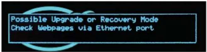
Fig 8-53: Possible Upgrade or Recovery Mode
Resetting to Factory Defaults
To do this, repeat the steps above but this time select the firmware file "AVN-PORTAL_x.x.xxxx_defaults.swu". You will then need to reconfigure the unit as required and save a new Config File for future use.
Please visit our website to download the latest firmware:
http://www.sonifex.co.uk/technical/software/index.shtml#AVN
You will need to unzip the file before it can be uploaded to the unit.
To access the "Recovery System firmware update page" please connect to the top Ethernet port and use an internet browser to enter the IP address 192.168.0.100:8080.
Note that your computer will need to have an IP address within the same range 192.168.0.x for this to work, for example 192.168.0.32.
9 Front Panel System Menu
9. Front Panel System Menu
The system menu, accessed via the front panel, offers alternative access to a limited set of options and information. Each layer of the menu structure, System Info apart from the main menu, has a 'BACK' option which ascends to the parent network menu. All layers have a 'CLOSE' option which exits the current menu and Display returns to the main screen.
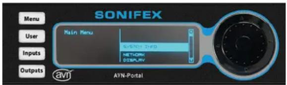
Fig 9-1: Main System Menu
All AVN portal series devices have the following options available in their
'Main Menu';
ure, System Info
parentNetwork
d→ Display
→ Close
Devices with a 'Meter Panel' (those with a 'Device ID' ending in a 'D') such as the 'AVN-PA8D' also have the following options available in their 'Main Menu';
→ Meters
System Info
The read only System Info menu item shows important information about
To access the system menu, press and hold the navigation centre button the unit. In particular, it shows the current IP addresses for the 2 network until the menu appears or press the 'Menu' button. The left side of the ports which will be required when accessing the embedded web server. The screen shows the current position within the menu structure. The right speed clock information is dynamic and shows the current status, whether shows the available menu selections or the options related to the current listening, Master or Slave. The ID of the current master is shown as well as menu item. To navigate through the menu, use either the navigation out the clock offset from the master clock if the unit is currently a slave. The up/down buttons or the inner rotary control to highlight the required iterate of the AC-DC power supply and DC power input is also dynamic and and then press either the centre button or the right button to confirm. Shows the voltage level of each supply.
configuration settings within the menu structure are presented either as a Main Menu → System Info list of options with a tick to show the current selection, or in a dialog which allows the value to be changed. For listed options, highlight the required → Device setting and press the centre button to select. Options presented in a dialog give guidance on how to change the current setting. To ascend up the menu structure, press either the navigation outer left button, or select the option 'back'.
→ IP Address
→ Subnet Mask
→ MAC Address
→ PTP Clock
→ Status
→ Domain Number
→ Master Offset
→ Profile
→ AC-DC Voltage
→ DC Voltage
→ Version
→ FP Version
→ Serial
→ SOM Serial
Network
The Network menu area allows the settings for the Ethernet and AoIP network ports to be edited. These settings correspond to the options shown on the Network web page. For a description of these items, pl refer to that section.
→ Network
→ Friendly Name
→ Ethernet Port
→ Address Mode
→ Static Settings
→ IP Address
→ Subnet Mask
→ Back
→ Close
→ Back
→ Close
→ AoIP Port
→ Address Mode
→ Static Settings
→ IP Address
→ Subnet Mask
→ Back
→ Close
→ Back
→ Close
→ Auto Multicast
→ Back
→ Close
Display
The Display menu area allows the screen contrast and LED brightness to be adjusted. These settings correspond to the options shown on the _Display Settings` webpage. For a description of these items, please refer to this section. For the screen contrast and LED brightness options, a dialog will be shown on the display and the current setting is changed by turning the navigation rotary control. The value is represented on screen with a sliding
→ Display
→ Screen Contrast
→ LED Brightness
→ Back
→ Close
Meters
The 'Meters' sub-menu allows the type of scale used on the meter display to be selected, it also allows adjustment of the meter displays brightness and allows any of the input or output channels to be selected and displayed full size on the input or output display.
9 Front Panel System Menu
→ Meters
→ Input Channel
→ Output Channel
→ Scale Selection
→ Displays Brightness
The 'Input Channel' sub-menu displays a list of the input channels and allows a stereo pair of channels or mono channel to be selected and displayed full size on the input display.
The 'Output Channel' sub-menu displays a list of the output channels and allows a stereo pair of channels to be selected and displayed full size on the output display.
The 'Scale Selection' sub-menu provides a list of different scale standards, selecting a standard applies that scale to the monitor panel, the list of scale standards and their properties is available in the 'Display Settings' subsection of the 'Embedded Web Server' section.
The 'Display Brightness' setting allows the user to modify the brightness of the backlight on the TFT meter displays.
10. Ember+ Interface
Each device in the AVN portal series has an Ember+ provider interface exposes various configuration options. It also allows the GPIO, virtual GPIO and the relay to be controlled and monitored by an external Ember+ consumer.
view and manipulate the various parameters that are made available in the Ember+ provider tree. In Ember+ viewer, nodes are identified by a blue dot that and parameters are indicated by a green leaf icon. Parameters whose names are shown in blue text can be modified by the user, all other parameters are read only.
Connecting to The Ember+ Interface
The Ember+ interface is available on the AoIP network connection using port 9000. The structure of the provider tree is similar to the system menu on the front panel. Each of the configuration options are arranged in branches grouped by function. Fig 10-1 shows a graphical representation of the root structure.
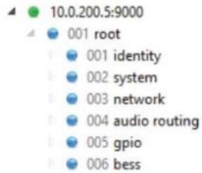
Fig 10-1: Ember+ Root Structure
Identity Node
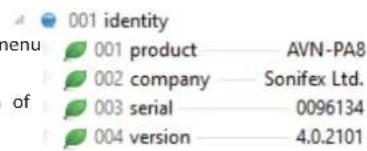
Fig 10-2: Ember+ Identity Branch Structure
Product
This specifies the type of product.
Company
This specifies the manufacturer of the product.
Serial
This specifies the serial number of the device.
Version
The configuration options are presented as either string or integer types. This specifies the current firmware version on the device. Where possible, integer type options are enumerated to indicate what each of the available setting values are. A full list of the options and values associated with each of the Ember+ parameters can be found in the 'Parameter Value Specification' sub-section of this handbook.
To read and write to the various parameters, the Ember+ protocol can be used. The screenshots in this section are obtained using the Ember+ Viewer tool which provides a graphical user interface (GUI) that can be used to
10 Ember+ Interface
System Node
4 002 system
fx 001 reboot
Fig 10-3: Ember+ System Branch Structure
Reboot
The device can be rebooted by invoking this function.
Network Node
The network node contains information on the network configuration of the unit.
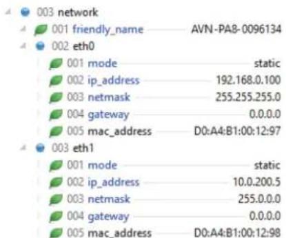
Fig 10-4: Ember+ Network Branch Structure
Friendly name
The name given to the device by the user. In Ember+ Viewer, this can be edited by selecting it from this menu. And clicking 'Change...'.
Eth0
Mode
Allows the user to select between 'Static' and 'Dynamic' addressing modes.
IP Address
Allows the user to enter an IP address for the device which is used when the device is in the 'Static' addressing mode.
Netmask
Allows the user to enter a subnet mask for the device which is used when the device is in the 'Static' addressing mode.
Gateway
Allows the user to enter a gateway address for the device which is used when the device is in the 'Static' addressing mode.
MAC Address
This specifies the MAC address of the port.
Eth1
Mode
Allows the user to select between 'Static' and 'Dynamic' addressing modes.
IP Address
Allows the user to enter an IP address for the device which is used when the device is in the 'Static' addressing mode.
Netmask
Allows the user to enter a subnet mask for the device which is used when the device is in the 'Static' addressing mode.
Gateway
Allows the user to enter a gateway address for the device which is used when the device is in the 'Static' addressing mode.
MAC Address
This specifies the MAC address of the port.
Audio Routing Node
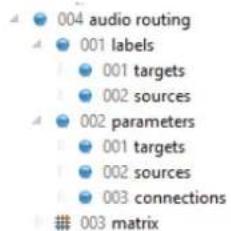
Fig 10-5: Ember+ Audio Routing Structure
Labels Node
Targets
A list of all the devices outputs, each of these outputs can be selected and the name of output changed.
Sources
A list of all the devices inputs, each of these inputs can be selected and the name of input changed.
Parameters Node
dTargets
A list of all the devices outputs, each of the outputs can have their specific settings changed. For example, a physical output on the PA8;
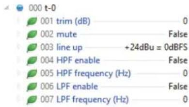
Fig 10-6: Ember+ Target Parameters (PA8 Physical Output)
Each of these options can be selected and adjusted.
Sources
A list of all the devices inputs, each of the inputs can have their specific settings changed. For example, a physical input on the PA8;
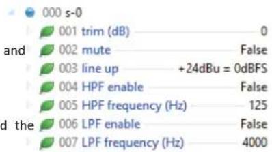
Fig 10-7: Ember+ Source Parameters (PA8 Physical Input)
Each of these options can be selected and adjusted.
10 Ember+ Interface
Connections
Matrix
This shows connections between input and output channels, for example Selecting matrix from the list bring up the following display;
Fig 10-8: Ember+ Connection Parameters shows a connection between the left channel of the first file playback input and the left channel of the first physical output.
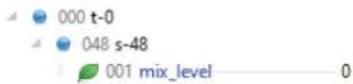
Fig 10-8: Ember+ Connection Parameters
Each of these connections provide the option to modify their 'mix level', this is how much the level of audio from the input channel is increased or decreased before reaching the output channel.
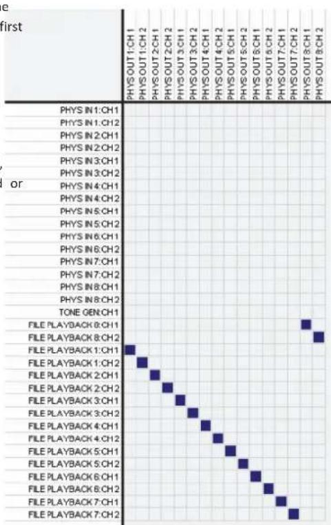
Fig 10-9: Ember+ Audio Routing Matrix
As seen in Fig 10-9: Ember+ Audio Routing Matrix the audio routing maPhysical Node displays all the devices input channels down the left-hand side and all the devices output channels along the top. Clicking on a box between an input and output channel causes audio to be routed from the input channel to the output channel. This routing can be removed by clicking on the same box. Right clicking on a routing or name allows parameters to be viewed or changed.
GPIO Nodes
The GPIO branch allows monitoring and control of the GPIO
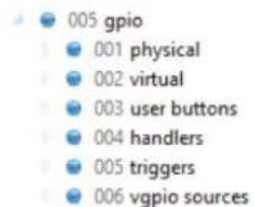
Fig 10-10: Ember+ GPIO Branch Structure
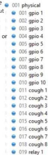
Fig 10-11: Ember+ Physical GPIO
Under the physical node are the physical GPIO nodes, the cough GPIO nodes, and the relay node.
GPIO
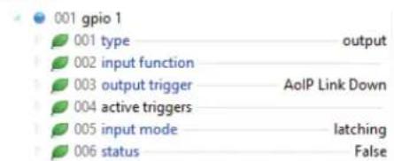
Fig 10-12: Ember+ Physical GPIO Parameters
10 Ember+ Interface
An example physical GPIO is shown in Fig 10-12: Ember+ Physical GPIO Cough Parameters.
Type
This enumerated integer parameter is the current port type. This parameter indicates whether the GPIO is disabled, or set to be an input or an output. The example is setup as an output.
Input Function
This string parameter is the function that will be activated when the port, when configured as an input, is asserted. The values that this parameter can be set to are listed under the 'handlers' node.
Output Trigger
String parameter with comma separated list of assigned triggers. The of the triggers that can be added to the list are available under the 'Triggers' node. The port is activated when a trigger is active.
Active Triggers
This lists the names of the output triggers that are active.
Input Mode
When the GPIO is configured as an input, this enumerated parameter configures whether the GPIO works in a latching or momentary mode.
Status
The status parameter represents the current state of the GPIO port regardless of whether the port is set as an input or an output. A value 'False' indicates the port is inactive and 'True' indicates the port is active. When the GPIO is configured as an output, a connected Ember+ consumption can modify the value of this parameter.
011 cough 1
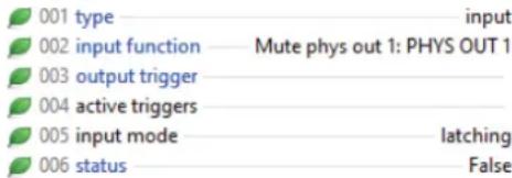
Fig 10-13: Ember+ Cough GPIO Parameters
An example cough GPIO is shown in Fig 10-13: Ember+ Cough GPIO Parameters.
Type
This enumerated integer parameter is the current port type. A cough GPIO can only be disabled or set up as an input. The example is setup as an input.
Input Function
This string parameter is the function that will be activated when the cough GPIO port is asserted. The values that this parameter can be set to are listed under the 'handlers' node. In the example this is set to mute the first physical output.
Output Trigger
This string parameter is the function that triggers the cough GPIO port when it is configured as an output, since the cough GPIO cannot be setup as a port output this parameter is unused.
Active Triggers
This lists the names of the output triggers that are active.
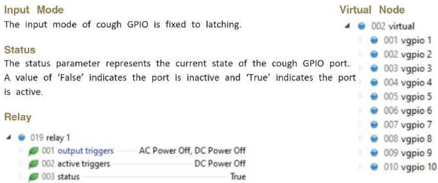
Fig 10-14: Ember+ Relay Parameters
Fig 10-15: Ember+ Virtual Node
Output Triggers
String parameter with comma separated list of assigned triggers. The of the triggers that can be added to the list are available under the 'Triggers' node.
Active Triggers
This read-only string parameter gives a comma separated list of the configured triggers that are currently active.
vGPIO
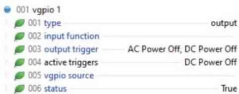
Fig 10-16: Ember+ vGPIO Parameters
Status Parameter
The status parameter represents the current state of the relay. A value of 'False' indicates the relay is inactive and 'True' indicates the relay is active.
This enumerated integer parameter is the current port type. This parameter indicates whether the virtual GPIO is disabled, or set to be an input or an output. The example is setup as an output.
10 Ember+ Interface
Input Function
This string parameter is the function that will be activated when the virtual GPIO, when configured as an input, is asserted. The values that this parameter can be set to are listed under the 'Handlers' node.
Output Trigger
String parameter with comma separated list of assigned triggers. The names of the triggers that can be added to the list are available under the 'Triggers' node. The port becomes active when a trigger is active. The example is set to be triggered if either the AC power is lost or the DC power is lost.
Active Triggers
A list of the output triggers that are currently active. In the example the DC power is currently off.
vGPIO Source
This string parameter lists the name of the remote unit that is assigned to control this virtual GPIO when it is configured as an input. The values that this parameter can be set to are listed under the 'vGPIO Sources' node.
Status
The status parameter represents the current state of the virtual GPIO port
regardless of whether the port is set as an input or an output. A value of 'False' indicates the port is inactive and a 'True' indicates the port is active. When the virtual GPIO is configured as an output, a connected Ember+ This is the function that is triggered when the button is active, this can be a comma separated list of handlers. Handlers can be found under the 'handlers' node.
User Buttons Node

3 user buttons
001 button 1
002 led 1
003 button 2
004 led 2
005 button 3
006 led 3
Fig 10-17: Ember+ User Buttons Node
Button

001 button 1
001 type
002 input function Mute phys out 1: PHYS OUT 1
003 input mode latching
004 status False

The button type can be either disabled or input.
Input Function
This is the function that is triggered when the button is active, this can be a active. comma separated list of handlers. Handlers can be found under the 'handlers' node.
Input Mode
The button can be set to operate in either latching or momentary mode. The list of triggers are values that can be used in an output triggers field, when the trigger becomes active the output becomes active.
Status
The current status of the button.
LED
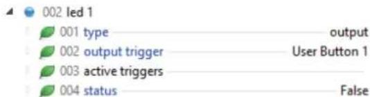
Fig 10-19: Ember+ LED Parameters
Type
An LED can either be disabled or setup as an output.
Output Trigger
This is a comma separated list of triggers, if any of the triggers become active the LED becomes active. Triggers can be found in the 'Triggers' node. Multicast Address This is a string which provides the address of the AoIP stream this can be either a unicast or multicast address which is the AoIP streams destination.
Active Triggers
A list of the output triggers that are currently active.
Status
This is the current status of the LED, when 'True' the LED is illuminated Channels
Handlers Node
The list of handlers are values that can be used in an input function field DSCP
when the function becomes active the handler becomes active.
Triggers Node
The list of triggers are values that can be used in an output triggers field, when the trigger becomes active the output becomes active.
vGPIO Sources
This is a list of virtual GPOs (outputs) available on the network that can be used and connected to virtual GPIs (inputs).
BESS Node
BESS Version
This is a string which provides the version of BESS being used.
Transmitters
Group
Audio
Stream Name
This is a string which provides the name of the audio over IP stream.
Port
This is an integer that is used to set the destination port of the AoIP stream
This is the number of channels the AoIP stream contains.
The DSCP parameter allows the precedence of the stream packets to be modified.
10 Ember+ Interface
Packet Time
Buffer Delay
Not all devices can handle lower packet times, if this is the case, the packet processing the buffer delay allows for smooth playback of digital streams in a time will need to be adjusted in order to be compatible with those device high latency network, the buffer delay is measured in samples.
This packet time can be set to either 125 μs, 250 μs, 333 μs, 1 ms or 4 ms.
The 'Packet Time' can only be set to 4 ms when the number of 'Channels' Steam Present
set to 2.
This is an integer which determine the current state of the added AoIP stream.
Multicast TTL
The Time to Live (TTL) option can be set to an integer value from 1 to
Stream Impaired
and is used to limit the time a packet spends on a network.
If the AoIP stream can no longer be accessed this field becomes 'True'.
Enable
Channels
Enables or disabled the transmission of the stream.
This indicates the number of channels of the received AoIP stream.
SDP
GUID
This field provides the SDP of the AoIP stream, this can be copied and
The GUID provides a unique ID in compliance with the Basic Ember+ Stream
to add an AoIP stream to another device manually.
Switching (BESS) Standard.
GUID
The GUID provides a unique ID in compliance with the Basic Ember+ Stream
Switching (BESS) Standard.
Receivers
Group
Audio
SDP
This allows the manual entry of SDP data in order to add an AoIP stream as
an input to the device.
Parameter Value Specification
This section provides a full list of the possible parameter values for the Ember+ interface. Integer values with a prefix of '0x' are in hexadecimal format.
→ Identity (Read only leaves that describe the unit)
→ Product
→ Company
→ Serial
→ Version
→ System
→ Reboot (Function)
→ Network
→ Friendly Name (String, max length 23-characters)
→ Port (Eth0 is upper port and Eth1 is lower port)
→ Mode (Integer)
→ 0 (Disabled)
→ 1 (Static)
→ IP Address (String, max length 15-character)
→ Netmask (String, max length 15-character)
→ Gateway (String, max length 15-character)
→ MAC Address (Read only)
→ Audio Routing
→ Labels (View the name given to each input and output channel)
→ Targets
→ t-* and label (Values cannot be changed via Ember+)
→ Sources
→ s-* and label (Values cannot be changed via Ember+)
→ Parameters
→ Targets
→ t-* (for physical outputs)
→ Trim (Integer)
→ -12 (Min)
→ +12 (Max)
→ Mute (Boolean)
→ Line up (Integer) (AVN-PA8/T/D and AVN-PM8/T/D only)
→ 0 (+15 dBu)
→ 1 (+18 dBu)
→ 2 (+20 dBu)
→ 3 (+22 dBu)
→ 4 (+24 dBu)
→ HPF Enable (Boolean)
→ False (Off)
→ True (On)
→ HPF Frequency (Integer)
→ 40 (Min)
→ 10000 (Max)
→ LPF Enable (Boolean)
→ False (Off)
→ True (On)
→ LPF Frequency (Integer)
→ 40 (Min)
→ 10000 (Max)
- * (for AoIP outputs)
→ Multicast Address (String)
→ Port (Integer)
→ 0 (Min)
→ 65535 (Max)
→ DSCP (Integer)
→ CS0 0
→ CS1 1
→ AF11 2
→ AF12 3
→ AF13 4
→ CS2 5
10 Ember+ Interface
→ AF21 6
→ AF22 7
→ AF23 8
→ CS3 9
→ AF31 10
→ AF32 11
→ AF33 12
→ CS4 13
→ AF41 14
→ AF42 15
→ AF43 16
→ CS5 17
→ VOICE ADMIT 18
→ EF PHB 19
→ CS6 20
→ CS7 21
→ Packet Time (Integer)
→ 125us 0
→ 250us 1
→ 333us 2
→ 1ms 3
→ 4ms 4
→ Multicast TTL
→ 1 (Min)
→ 255 (Max)
→ Trim (Integer)
→ -12 (Min)
→ +12 (Max)
→ Mute (Boolean)
→ Line up (Integer) (AVN-PA8/T/D and AVN-PM8/T/D only)
→ 0 (+15 dBu)
→ 1 (+18 dBu)
→ 2 (+20 dBu)
→ 3 (+22 dBu)
→ 4 (+24 dBu)
→ HPF Enable (Boolean)
→ False (Off)
→ True (On)
→ HPF Frequency (Integer)
→ 40 (Min)
→ 10000 (Max)
→ LPF Enable (Boolean)
→ False (Off)
→ True (On)
→ LPF Frequency (Integer)
→ 40 (Min)
→ 10000 (Max)
→ Sources
→ s-* (for physical input)
→ Trim (Integer)
→ -12 (Min)
→ +12 (Max)
→ Mute (Boolean)
→ False (Off)
→ True (On)
→ Line up (Integer) (AVN-PA8/T/D and AVN-PM8/T/D only)
→ 0 (+15 dBu)
→ 1 (+18 dBu)
→ 2 (+20 dBu)
→ 3 (+22 dBu)
→ HPF Enable (Boolean)
→ False (Off)
→ True (On)
→ HPF Frequency (Integer)
→ 40 (Min)
→ 10000 (Max)
→ LPF Enable (Boolean)
→ False (Off)
→ True (On)
→ LPF Frequency (Integer)
→ 40 (Min)
→ 10000 (Max)
→ Preamp Gain (dB) (Double) (AVN-PM8/T/D only)
→ 16 (Min)
→ 76 (Max)
→ Signal Level (Integer) (AVN-PM8/T/D only)
→ Mic 0
→ Line 1
→ Phantom Power (Boolean) (AVN-PM8/T/D only)
→ s-* (for file playback input)
→ Trim (Integer)
→ -12 (Min)
→ +12 (Max)
→ Mute (Boolean)
→ HPF Enable (Boolean)
→ False (Off)
→ True (On)
→ HPF Frequency (Integer)
→ 40 (Min)
→ 10000 (Max)
→ LPF Enable (Boolean)
→ False (Off)
→ True (On)
→ LPF Frequency (Integer)
→ 40 (Min)
→ 10000 (Max)
→ s-* (for tone generator input)
→ Trim (Integer)
→ -12 (Min)
→ +12 (Max)
→ Mute (Boolean)
→ Mode (Integer)
→ Sine 0
→ Saw 1
→DTMF 2
→ Frequency (Hz) (Integer)
→ 100 (Min)
→ 10000 (Max)
→ DTMF Digit (Integer)
→ 1 0
→ 2 1
→ 3 2
→ 4 3
→ 5 4
→ 6 5
→ 7 6
→ 8 7
→ 9 8
→ 0 9
→ A 10
→ B 11
→ C 12
→ D 13
→ * 14
→ # 15
→ s-* (for AoIP input)
→ input_buff_id (integer) (read-only)
→ in_buff_delay (integer)
→ 1 (Min)
→ 1023 (Max)
10 Ember+ Interface
→ Trim (Integer)
→ -12 (Min)
→ +12 (Max)
→ Mute (Boolean)
→ HPF Enable (Boolean)
→ False (Off)
→ True (On)
→ HPF Frequency (Integer)
→ 40 (Min)
→ 10000 (Max)
→ LPF Enable (Boolean)
→ False (Off)
→ True (On)
→ LPF Frequency (Integer)
→ 40 (Min)
→ 10000 (Max)
→ Connections
→ t-* (Target Channel)
→ s-* (Source Channel)
→ Mix Level (Integer)
→ -100 (Min)
→ 10 (Max)
→ Matrix
→ Click in the grid to create a connection between two channels
→ GPIO
→ Physical
→ GPIO *
→ Type (Integer)
→ 0 (Disabled)
→ 1 (Input)
→ 2 (Output)
→ Input Function (String)
→ Handler leaf value found in handler section (Example: Mute phys out 1: PHYS OUT 1)
→ Output Trigger (String)
→ Trigger leaf value found in trigger section (Example: Eth Link Down)
→ Input Mode (Integer)
→ 0 (Latching)
→ 1 (Momentary)
→ Status (Boolean)
→ False (Inactive input/output)
→ True (Active input/output)
→ Cough *
→ Type (Integer)
→ 0 (Disabled)
→ 1 (Input)
→ Input Function (String)
→ Handler leaf value found in handler section (Example: Mute phys out 1: PHYS OUT 1)
→ Output Trigger (String)
→ Trigger leaf value found in trigger section (Example: Eth Link Down)
→ Input Mode (Read only, Latching)
→ Status (Boolean)
→ False (Inactive input/output)
→ True (Active input/output)
→ Relay *
→ Output Triggers (String)
→ Trigger leaf value found in trigger section (Example: Eth Link Down) for multiple triggers follow this value with a comma and another trigger leaf value from the trigger section (Example: Eth Link Down, AoIP Link Down)
→ Active Triggers (String)
→ Trigger leaf values of active triggers (Example: Eth Link Down) for multiple triggers follow this value with a comma and another trigger leaf value from the trigger section (Example: Eth Link Down, AoIP Link Down)
→ Status (Read only, Boolean)
→ False (Inactive input/output)
→ True (Active input/output)
→ Virtual
→ vGPIO *
→ Type (Integer)
→ 0 (Disabled)
→ 1 (Input)
→ 2 (Output)
→ Input Function (String)
→ Handler leaf value found in handler section (Example: Mute phys out 1: PHYS OUT 1)
→ Output Trigger (String)
→ Trigger leaf value found in trigger section (Example: Eth Link Down)
→ vGPIO Source (String)
→ The name of any other devices vGPIO (Example: vGPO1@Friendly-Name
→ Status (Boolean)
→ False (Inactive input/output)
→ True (Active input/output)
→ User Buttons
→ Button *
→ Type (Integer)
→ 0 (Disabled)
→ 1 (Input)
→ Input Function (String)
→ Handler leaf value found in handler section (Example: Mute phys out 1: PHYS OUT 1)
→ Input Mode (Integer)
→ 0 (Latching)
→ 1 (Momentary)
→ Status (Boolean)
→ False (Inactive input/output) → True (Active input/output)
→ LED *
→ Type (Integer)
→ 0 (Disabled)
→ 2 (Output)
→ Output Trigger (String)
→ Trigger leaf value found in trigger section (Example: Eth Link Down)
→ Status (Boolean)
→ False (Inactive input/output)
→ True (Active input/output)
→ Handlers
→ H-* and value, used to perform functions on the device using GPIO.
→ Triggers
→ T-* and value, used to set triggers on the device when configuring GPIO.
→ vGPIO Sources
→ vGPIO*@Friendly-Name list of vGPIO outputs from other devices, these can be used as triggers for vGPIO inputs.
10 Ember+ Interface
→ BESS
→ BESS Version (String) (Read-only)
→ Transmitters
→ Group *
→ Audio *
→ Stream Name (String)
→ Multicast Address (String)
→ Port (Integer)
→ 1024 (Min)
→ 65535 (Max)
→ Channels (Integer) (Read-Only)
→ DSCP (Integer)
→ CS0 0
→ CS1 1
→ AF11 2
→ AF12 3
→ AF13 4
→ CS2 5
→ AF21 6
→ AF22 7
→ AF23 8
→ CS3 9
→ AF31 10
→ AF32 11
→ AF33 12
→ CS4 13
→ AF41 14
→ AF42 15
→ AF43 16
→ CS5 17
→ VOICE ADMIT 18
→ EF PHB 19
→ CS6 20
→ CS7 21
→ Packet Time (Integer)
→ 125us 0
→ 250us 1
→ 333us 2
→ 1ms 3
→ 4ms 4
→ Multicast TTL
→ 1 (Min)
→ 255 (Max)
→ Enable (Boolean)
→ SDP (String) (Read-Only)
→ GUID (String) (Read-Only)
→ Receivers
→ Group *
→ Audio *
→ SDP (String)
→ Buffer Delay (Integer)
→ 1 (Min)
→ 1023 (Max)
→ Stream Present (Integer) (Read-Only)
→ Both 0
→ Primary 1
→ Secondary 2
→ Lost 3
→ Stream Impaired (Boolean) (Read-Only)
→ Channels (Integer) (Read-Only)
→ GUID (String) (Read-Only)
11. Technical Specifications
AVN-PA8/T/D 8 Stereo Analogue Line Inputs & Outputs, AES67 Display Portal
Audio-Over-IP Specification
| Open Standards: RAVENNA, AES67 | |
| Device Discovery: Bonjour (mDNS / DNS-SD), SAP | |
| Audio Delivery: RTP/UDP over IPv4 multicast and unica | |
| QoS: DiffServ | |
| Stream Management: RTSP/SDP | |
| Control: Web server/Ember+ | |
| Format: Linear PCM 24-bit (L24) | |
| Channels Per Stream: Up to 8 | |
| Packet Time: 125μs, 333μs, 250μs, 1ms, 4ms (2 Channel Streams Only) | |
| Transmit Streams: Up to 8 | |
| Sample Rate: 48 kHz |
Ember+ Interface Connection
| Interface Type: | Provider |
| Network Interface: | AoIP port and ethernet port |
| Port: 9000 |
Timing Synchronisation
| Profile Support: | Default, AES67 Media, SMPTE, AES-SMPTE, Custom |
| Timing Protocol: | PTPv2, IEEE1588-2008 |
Balanced Line Inputs
| Input Impedance: > 20kΩ balanced | |
| OdBFS Line-Up: Adjustable +15/+18/+20/+22/+24dBu | |
| Frequency Response: 20Hz to 20kHz, +0/-0.2dB |
| THD+N: < -110dBFS, -30dBFS, 20Hz to 20kHz, 20kHz BW |
| Noise: -110dBFS, 20kHz BW, Rs=200Ω |
| Crosstalk: < -100dB |
| Common Mode Rejection: > 70dB @ 1kHz |
Balanced Line Outputs
| Output Impedance: | < 50Ω balanced |
| 0dBFS Line-Up: Adjustable +15/+18/+20/+22/+24dBu | |
| Frequency Response: | 20Hz to 20kHz, +0/-0.2dB |
| THD+N: < -110dBFS, -30dBFS, 20Hz to 20kHz, 20kHz BW | |
| Noise: | -110dBFS, 20kHz BW, Rs=200Ω |
Connections
| AVN-PA8/D | |
| Inputs: | 2 D-Sub (DB-25) connections (TASCAM AES-59 analogue pinout) paralleled with 8 RJ45 connections (StudioHub+ pinout). |
| Outputs: | 2 D-Sub (DB-25) connections (TASCAM AES-59 analogue pinout) paralleled with 8 RJ45 connections (StudioHub+ pinout). |
| GPIO: | 1 D-Sub (DA-15) connections. |
| Network: | 2 x Gigabit Ethernet, RJ45's.1 x SFP fibre. |
| Power: | Mains AC Input: Universal filtered IEC, continuously rated 85-264VAC, 47-63Hz, 20W. |
| DC Input: | 4-pin 7.5A power jack socket, 10-14VDC. |
| Fuse Rating: | Anti-surge fuse 2A 20mm x 5mm. |
| AVN-PA8T/D | |
| Inputs: | 2 24-Pin Phoenix style terminal blocks (Analogue pinout) |
11 Technical Specifications
Outputs: 2 24-Pin Phoenix style terminal blocks. (Analogue pinout)
GPIO: 1 24-Pin Phoenix style terminal blocks.
Network: 2 x Gigabit Ethernet, RJ45's. 1 x SFP fibre.
Power: Mains AC Input: Universal filtered IEC, continuously rated 85-264VAC, 47-63Hz, 20W.
DC Input: 4-pin 7.5A power jack socket, 10-14VDC.
Fuse Rating: Anti-surge fuse 2A 20mm x 5mm.
Equipment Type
| AVN-PA8: Advanced audio routing, metering and equalisation unit with analogue inputs, analogue outputs, and RAVENNA AoIP. |
| AVN-PA8D: Advanced audio routing, metering and equalisation unit with analogue inputs, analogue outputs, RAVENNA AoIP, and a detailed customisable display. |
| AVN-PA8T: Advanced audio routing, metering and equalisation unit with terminal type analogue inputs, terminal type analogue outputs, and RAVENNA AoIP. |
| AVN-PA8TD: Advanced audio routing, metering and equalisation unit with terminal type analogue inputs, terminal type analogue outputs, RAVENNA AoIP, and a detailed customisable display. |
Physical Specification
| Dimensions (Raw): | 48.3cm (W) x 17.5cm (D) x 4.4cm (H) (1U) |
| 19" (W) x 6.9" (D) x 1.8" (H) (1U) | |
| Dimensions (Boxed): | 59cm (W) x 28cm (D) x 11cm (H) |
| 23" (W) x 11" (D) x 4.3" (H) |
Weight: Nett: 3.0kg Gross: 3.7kg Nett: 6.6lbs Gross: 8.1lbs
Accessories
| AVN-DC150: | 150W DC power supply with KPJX-4S plug. |
| AVN-HA1: | Analogue Headphone Amplifier. |
AVN-PD8/T/D 8 Stereo Digital Line Inputs & Outputs, AES67 Portal
Audio-Over-IP Specification
| Open Standards: | RAVENNA, AES67 |
| Device Discovery: | Bonjour (mDNS / DNS-SD), SAP |
| Audio Delivery: | RTP/UDP over IPv4 multicast and unicast |
| QoS: | DiffServ |
| Stream Management: | RTSP/SDP |
| Control: | Web server/Ember+ |
| Format: | Linear PCM 24-bit (L24) |
| Channels Per Stream: | Up to 8 |
| Packet Time: | 125μs, 333μs, 250μs, 1ms, 4ms (2 Channel Streams Only) |
| Transmit Streams: | Up to 8 |
| Sample Rate: | 48 kHz |
Ember+ Interface Connection
| Interface Type: | Provider |
| Network Interface: | AoIP port and ethernet port |
| Port: 9000 |
Timing Synchronisation
| Profile Support: | Default, AES67 Media, SMPTE, AES-SMPTE, Custom |
| Timing Protocol: | PTPv2, IEEE1588-2008 |
Balanced Digital Inputs
Input Impedance: > 20kΩ balanced
Technical Specifications 11
0dBFS Line-Up: Adjustable +15/+18/+20/+22/+24dBu
Frequency Response: 20Hz to 20kHz, +0/-0.2dB
THD+N: < -110dBFS, -30dBFS, 20Hz to 20kHz, 20kHz BW
Noise: -110dBFS, 20kHz BW, Rs=200Ω
Crosstalk: < -100dB
Common Mode Rejection: > 70dB @ 1kHz
Balanced Digital Outputs
Output Impedance: < 50Ω balanced
0dBFS Line-Up: Adjustable +15/+18/+20/+22/+24dBu
Frequency Response: 20Hz to 20kHz, +0/-0.2dB
THD+N: < -110dBFS, -30dBFS, 20Hz to 20kHz, 20kHz BW
Noise: -110dBFS, 20kHz BW, Rs=200Ω
Connections
AVN-PD8/D
Inputs: 1 D-Sub (DB-25) connection (TASCAM AES-5 digital pinout) paralleled with 8 RJ45 connections (StudioHub+ pinout).
Outputs: 1 D-Sub (DB-25) connection (TASCAM AES-59 digital pinout) paralleled with 8 RJ45 connections (StudioHub+ pinout).
GPIO: 1 D-Sub (DA-15) connections.
Network: 2 x Gigabit Ethernet, RJ45's. 1 x SFP fibre.
Power: Mains AC Input: Universal filtered IEC, continuously rated 85-264VAC, 47-63Hz, 20W.
DC Input: 4-pin 7.5A power jack socket, 10-14VDC.
Fuse Rating: Anti-surge fuse 2A 20mm x 5mm.
AVN-PD8T/D
Inputs: 2 24-Pin Phoenix style terminal blocks. (Digital pinout)
Outputs: 2 24-Pin Phoenix style terminal blocks. (Digital pinout)
GPIO: 1 24-Pin Phoenix style terminal blocks.
Network: 2 x Gigabit Ethernet, RJ45's. 1 x SFP fibre.
Power: Mains AC Input: Universal filtered IEC, continuously rated 85-264VAC, 47-63Hz, 20W.
DC Input: 4-pin 7.5A power jack socket, 10-14VDC.
Fuse Rating: Anti-surge fuse 2A 20mm x 5mm.
Equipment Type
AVN-PD8: Advanced audio routing, metering and equalisation unit with digital inputs, digital outputs, and RAVENNA AoIP.
AVN-PD8D: Advanced audio routing, metering and equalisation unit with digital inputs, digital outputs, RAVENNA AoIP, and a detailed customisable display.
AVN-PD8T: Advanced audio routing, metering and equalisation unit with terminal type digital inputs, terminal type analogue outputs, and RAVENNA AoIP.
AVN-PD8TD: Advanced audio routing, metering and equalisation unit with terminal type digital inputs, terminal type analogue outputs, RAVENNA AoIP, and a detailed customisable display.
11 Technical Specifications
Physical Specification
| Dimensions (Raw): 48.3cm (W) x 17.5cm (D) x 4.4cm (H) (1U) |
| 19" (W) x 6.9" (D) x 1.8" (H) (1U) |
| Dimensions (Boxed): 59cm (W) x 28cm (D) x 11cm (H) |
| 23" (W) x 11" (D) x 4.3" (H) |
Weight: Nett: 3.0kg Gross: 3.7kg Nett: 6.6lbs Gross: 8.1lbs
Accessories
| AVN-DC150: 150W DC power supply with KPJX-4S plug.AVN-HD1: Digital Headphone Amplifier. |
AVN-PM8/T/D 8 Mic/Line Inputs, 8 Line Outputs, Terminal Block, AES67 Portal
Audio-Over-IP Specification
| Open Standards: RAVENNA, AES67 | |
| Device Discovery: Bonjour (mDNS / DNS-SD), SAP | |
| Audio Delivery: RTP/UDP over IPv4 multicast and unicast | |
| QoS: | DiffServ |
| Stream Management: | RTSP/SDP |
| Control: | Web server/Ember+ |
| Format: | Linear PCM 24-bit (L24) |
| Channels Per Stream: | Up to 8 |
| Packet Time: | 125μs, 333μs, 250μs, 1ms, 4ms (2 Channel Streams Only) |
| Transmit Streams: | Up to 8 |
| Sample Rate: | 48 kHz |
Ember+ Interface Connection
| Interface Type: | Provider |
| Network Interface: | Ethernet port and AoIP port |
| Port: | 9000 |
Timing Synchronisation
| Profile Support: | Default, AES67 Media & Custom profiles |
| Timing Protocol: | PTPv2, IEEE1588-2008 |
Microphone Inputs
| Input Impedance: | >2.5kΩ balanced |
| Gain Range: | 0dB to +60dB |
| 0dBFS Line-Up: | Adjustable in steps of 3dB from -58dBu to +2dBu |
| Frequency Response: | 20Hz to 20kHz, +0/-0.2dB |
| Noise: | -127dBu, 20kHz BW, Rs=200Ω ref. 76dB gain |
Balanced Line Inputs
| Input Impedance: | >20kΩ balanced |
| 0dBFS Line-Up: Adjustable +15/+18/+20/+22/+24dBu | |
| Frequency Response: | 20Hz to 20kHz, +0/-0.2dB |
| THD+N: | <-110dBFS, -30dBFS, 20Hz to 20kHz, 20kHz BW |
| Noise: | -110dBFS, 20kHz BW, Rs=200Ω |
| Crosstalk: | <-100dB |
| Common Mode Rejection: >70dB @ 1kHz | |
Balanced Line Outputs
| Output Impedance: | < 50Ω balanced |
| 0dBFS Line-Up: Adjustable | +15/+18/+20/+22/+24dBu |
| Frequency Response: | 20Hz to 20kHz, +0/-0.2dB |
| THD+N: | < -110dBFS, -30dBFS, 20Hz to 20kHz, 20kHz BW |
| Noise: | -110dBFS, 20kHz BW, Rs=200Ω |
Connections
| AVN-PM8/D | |
| Inputs: | XLR connectors with phantom power (toggle). |
| Outputs: | RJ45 connections (StudioHub+ pinout). |
| GPIO: | 1 D-Sub (DA-15) connections. |
Technical Specifications 11
Network: 2 x Gigabit Ethernet, RJ45's. 1 x SFP fibre.
Power: Mains AC Input: Universal filtered IEC, continuously rated 85-264VAC, 47-63Hz, 20W.
DC Input: 4-pin 7.5A power jack socket, 10-14VDC.
Fuse Rating: Anti-surge fuse 2A 20mm x 5mm.
AVN-PM8T/D
Inputs: 1 24-Pin Phoenix style terminal blocks. (Analogue pinout)
Outputs: 2 24-Pin Phoenix style terminal blocks. (Analogue pinout)
GPIO: 1 24-Pin Phoenix style terminal blocks.
Network: 2 x Gigabit Ethernet, RJ45's. 1 x SFP fibre.
Equipment Type
AVN-PM8: Advanced audio routing, metering and equalisation unit with analogue mic/line inputs, analogue outputs, and RAVENNA AoIP.
AVN-PM8D: Advanced audio routing, metering and equalisation unit with analogue mic/line inputs, analogue outputs, RAVENNA AoIP, and a detailed customisable display.
AVN-PM8T: Advanced audio routing, metering and equalisation unit with terminal type analogue mic/line inputs, terminal type analogue outputs, and RAVENNA AoIP.
AVN-PM8TD: Advanced audio routing, metering and equalisation unit with terminal type analogue mic/line inputs, terminal type analogue outputs, RAVENNA AoIP, and a detailed customisable display.
Physical Specification
| Dimensions (Raw): | 48.3cm (W) x 17.5cm (D) x 4.4cm (H) (1U)19" (W) x 6.9" (D) x 1.8" (H) (1U) |
| Dimensions (Boxed): | 59cm (W) x 28cm (D) x 11cm (H)23" (W) x 11" (D) x 4.3" (H) |
| Weight: | Nett: 3.0kg Gross: 3.7kgNett: 6.6lbs Gross: 8.1lbs |
Accessories
| AVN-DC150: | 150W DC power supply with KPJX-4S plug. |
| AVN-HA1: | Analogue Headphone Amplifier. |
12 Additional Information
12. DSCP Names
| DSCP Name DS Field Value IP Precedence (Description) | ||
| CS0 0: Best Effort | ||
| CS1, AF11-AF13 8, 10, 12, 14 1: Priority | ||
| CS2, AF21-AF23 16, 18, 20, 22 2: Immediate | ||
| CS3, AF31-AF33 24, 26, 28, 30 3: Flash (mainly used for voice signalling) | ||
| CS4, AF41-AF43 32, 34, 36, 38 4: Flash Override | ||
| CS5, EF PHB 40, 46 5: Critical (mainly used for RTP) | ||
| VOICE ADMIT 44 | 5: Critical (uses Call Admission Control) | |
| CS6 | 48 | 6: Internetwork Control |
| CS7 | 56 | 7: Network Control |
Table 12-1: DSCP Names & Their Corresponding IP Precedence
Table 12-1 shows the corresponding IP precedence for the DSCP names used in the PTP Profiles and AoIP Stream Settings. For more information on the types of DSCP name, see the following documents;
• CS: Class Selector (RFC 2474)
- AFxy: Assured Forwarding (x= class, y = Drop Precedence) (RFC 2597)
• EF: Expedited Forwarding (RFC 3246)
Notes
SONIFEX
www.sonife
t:+44 (0)1933 650 700
f:+44 (0)1933 650 726
sales@sonifex.co.uk
x . c o . u k
- Multi-Channel Audio Interfaces Using AES67 AoIP - AVN Portals
- AVN-Portals Handbook
- Contents
- SONIFEX
- Register Online for an Extended 2 Year Warranty
- Warranty
- Product Warranty - 2 Year Extended Thi
- Sonifex Warranty & Liability Terms & Conditions
- Definitions
- Unpacking Your Product
- Item Quantity
- Safety & Installation of Mains Operated Equipment
- Repairs & Returns
- CE Conformity
- Voltage Setting Checks
- Fuse Rating
- Power Cable & Connection
- Safety & Installation
- WEEE Directive
- Atmosphere/Environment
- Multi-Channel Audio Mix Engines Using AES67 AoIP, AVN Portals Introduction
- AVN-Portals
- Headphone Distribution System
- Quick Start Guide
- Quick Start Guide
- Installation
- Network Connection
- Audio Inputs
- Audio Outputs
- ted GPIO
- Power Supply
- Front Panel Controls, Indicators & Displays
- Status Indicators
- AoIP
- Ethernet
- Alarm
- Front Panel Controls, Indicators CE Conformity
- Clock
- AC PSU
- DC PSU
- Menu Button
- User Buttons
- OLED Display
- CE Conformity | Controls, Indicators & Displays
- Navigation Control
- Reset Button
- Power Button
- AVN-PA8/T/D 8 Stereo Analogue Line Inputs & Outputs, AES67 Display Portal
- Rear Panel Connections
- AVN-PA8/T/D
- RJ45 Stereo Line Input Connections
- D-Sub (DB-25) Stereo Line Output Connections
- RJ45 Stereo Line Output Connections
- D-Sub (DA-15) GPIO Connection
- AVN-PA8/T/D 5
- Block 1
- Block 2
- 24-Pin Phoenix Style Stereo Line Output Terminal Connections
- Network Interfacing RJ45 Connections
- Mains Fuse
- Mains AC Input
- SFP Interface
- AVN-PD8/T/D 8 Stereo Digital Line Inputs & Outputs, AES67 Portal
- AVN-PD8/T/D
- 24-Pin Phoenix Style Stereo Digital Input Terminal Connection
- AVN-PD8/T/D 6
- 24-Pin Phoenix Style GPIO Terminal Connection
- AVN-PM8/T/D 8 Mic/Line Inputs, 8 Line Outputs, Terminal Block, AES67 Portal
- AVN-PM8/T/D
- 24-Pin Phoenix Style Stereo Line Input Terminal Connections
- AVN-PM8/T/D 7
- 12V DC Input
- Embedded Web Server 8
- Embedded Web Server
- Embedded Web Server
- Information
- Device Information
- PTP Clock Information
- Ethernet Network Information
- Audio Network Information
- Configuration
- Password
- made Retype Password
- Network
- Removing Password Protection
- Device Name & Security
- HTTP Port
- Network Defaults
- PTP Profiles Web Page
- PTP Profiles
- Profile Settings
- PTP Profiles Defaults
- Active Profile: Default
- Default Profile
- AES67 Media Profile
- SMPTE Profile
- AES-SMPTE Profile
- Custom Profile
- Display Settings
- Status LED Brightness
- Screen Saver Timeout
- User Button 'N' Function
- Power Button Enabled
- AC PSU Status LED
- Meter Panel Settings
- Meter Scale
- Brightness
- Meter Mode
- Channel Idents
- Phase Metering
- Audio Routing
- Add an AoIP Input Stream
- AoIP Tab
- Automatic Discovery
- Manual Entry
- General Tab
- EQ Tab
- Configuring AoIP Inputs
- Add an AoIP Output Stream
- Stream Name
- or Address
- Channels
- DSCP
- Packet Time
- TTL
- Add a File Playback Input
- Configuring Physical Inputs
- All Devices
- AVN-PA8/T/D
- Configuring Physical Outputs
- AVN-PA8/T/D and AVN-PM8/T/D
- Configuring the Tone Generator
- Adding A DSP Function
- Configuring DSP Outputs
- Collapse Inputs/Outputs
- Expand Inputs/Outputs
- Filtering Inputs/Outputs
- Show/Hide Input/Output Status Icons
- Routing
- Add Input
- Virtual GPIO
- Cough
- Event
- User Button
- Available Ports
- Input Mode (Physical GPI only)
- Momentary
- Latching
- vGPIO Source (Virtual GPI only)
- Available Events
- Eth Link Down
- AoIP Link Down
- AC Power Off
- DC Power Off
- PTP Sync Lost
- Digital Lock Lost n (AVN-PD8 Only)
- DSP Function n - x
- None
- eDTMF Detect
- Available Buttons
- Add Output
- Type
- Physical GPIO
- User LED
- Relay
- Mute Physical Input n: x
- Mute Physical Output n: x
- Mute Tone Generator n: x
- Mute File Playback Input: x
- Mute AoIP Input n: x
- Mute AoIP Output n: x
- Stop AoIP Output n: x
- Available LEDs
- Available Relays
- Routing Grid
- Creating Routings
- Lightbulbs
- Quick Delete
- Non-routable Squares
- Configuring Connection
- Invert Input State
- SNMP Settings
- System Location
- System Contact
- Community
- Trap Destination
- Front Panel System Menu
- System
- Reboot or Factory Reset
- Recovery & Reinstalling the Main Firmware
- Resetting to Factory Defaults
- Front Panel System Menu
- System Info
- Display
- Meters
- Ember+ Interface
- Connecting to The Ember+ Interface
- Identity Node
- Product
- Company
- Serial
- Version
- Ember+ Interface
- System Node
- Reboot
- Network Node
- Friendly name
- Eth0
- Mode
- IP Address
- Netmask
- Gateway
- MAC Address
- Eth1
- Audio Routing Node
- matrix
- Labels Node
- Targets
- Sources
- Parameters Node
- dTargets
- Connections
- Matrix
- GPIO Nodes
- GPIO
- Input Function
- Output Trigger
- Active Triggers
- Input Mode
- Status
- Output Triggers
- vGPIO
- Status Parameter
- vGPIO Source
- User Buttons Node
- Button
- LED
- Handlers Node
- Triggers Node
- vGPIO Sources
- BESS Node
- BESS Version
- Transmitters
- Port
- Buffer Delay
- Multicast TTL
- Stream Impaired
- Enable
- SDP
- GUID
- Receivers
- Group
- Audio
- Parameter Value Specification
- Technical Specifications
- AVN-PA8/T/D 8 Stereo Analogue Line Inputs & Outputs, AES67 Display Portal
- Technical Specifications
- Technical Specifications 11
- Balanced Digital Outputs
- AVN-PD8/D
- AVN-PD8T/D
- Equipment Type
- AVN-PM8/T/D 8 Mic/Line Inputs, 8 Line Outputs, Terminal Block, AES67 Portal
- AVN-PM8T/D
- Additional Information
- DSCP Names
Brand : Sonifex
Model : AVN-PM8
Category : Hand blender