AT-OME-RX21 - Audio/video converter Atlona - Free user manual and instructions
Find the device manual for free AT-OME-RX21 Atlona in PDF.


| Product Type | Audio/Video Converter (HDBaseT Receiver) |
| Model | AT-OME-RX21 |
| Brand | Atlona |
| Dimensions (W x D x H) | 160 x 100 x 25 mm |
| Weight | 0.5 kg |
| Power Supply | 12V DC / 1A (PoE supported) |
| Power Consumption | 7.5W max |
| Video Input | 1x HDMI (Type A, Female) |
| Video Output | 1x HDMI (Type A, Female), 1x HDBaseT (RJ45) |
| Max Resolution | 4K @ 60 Hz 4:4:4 (up to 18 Gbps) |
| Audio Support | LPCM 2.0/5.1/7.1, Dolby Digital/DTS-HD |
| HDBaseT Distance | Up to 100 m (Cat6/6a) |
| Control | IR, RS-232, LAN |
| Mounting | Desk or wall mountable |
| Operating Temperature | 0°C to 40°C |
| Storage Temperature | -20°C to 60°C |
| Humidity | 20% to 90%, non-condensing |
| Maintenance | Wipe with dry cloth; no liquid cleaners. |
| Safety | Use only included power supply; keep away from moisture. |
| Spare Parts / Repairability | Internal components not user-serviceable. Contact Atlona support. |
| Certifications | FCC, CE, RoHS |
| Warranty | Limited 10-year warranty |
Frequently Asked Questions - AT-OME-RX21 Atlona
User questions about AT-OME-RX21 Atlona
0 question about this device. Answer the ones you know or ask your own.
Ask a new question about this device
Download the instructions for your Audio/video converter in PDF format for free! Find your manual AT-OME-RX21 - Atlona and take your electronic device back in hand. On this page are published all the documents necessary for the use of your device. AT-OME-RX21 by Atlona.
USER MANUAL AT-OME-RX21 Atlona
Switcher for HDMI and VGA
with Ethernet-Enabled HDBaseT Output
Version Information
Version Release Date Notes
5 Apr 2024 Updated warranty information; new color format
Sales, Marketing, and Customer Support
Main Office
Atlona Incorporated
70 Daggett Drive
San Jose, CA 95134
United States
Office: +1.408.962.0515
Sales and Customer Service Hours
Monday - Friday: 6:00 a.m. - 4:30 p.m. (PST)
https://atlona.com/
International Headquarters
Atlona International AG
Tödistrasse 18
8002 Zürich
Switzerland
Office: +41.43.508.4321
Sales and Customer Service Hours
Monday - Friday: 09:00 - 17:00 (UTC +1)
Operating Notes

IMPORTANT: Visit http://www.atlona.com/product/AT-HDVS-200-TX and http://www.atlona.com/product/AT-HDVS-200-TX-PSK for the latest firmware updates and User Manual.
Consumer Electronics Control (CEC): Atlona has confirmed proper CEC functionality with several current models of Samsung, Panasonic, and Sony displays. However, it is not guaranteed that CEC will work with all displays. Many manufacturers do not support the CEC "off" command, and older displays use proprietary commands. Atlona only supports displays that use the CEC command structure defined in HDMI 1.2a. It is recommended that dealers request an evaluation product from Atlona, before designing a system using the CEC protocol. If this is not possible, then other control methods will need to be considered, in order to control displays using Atlona products.
Warranty

To view the product warranty, use the following link or QR code:
https://atlona.com/warranty/.
Safety and Certification
CAUTION
RISK OF ELECTRIC SHOCK
DO NOT OPEN
CAUTION: TO REDUCT THE RISK OF
ELECTRIC SHOCK
DO NOT OPEN ENCLOSURE OR EXPOSE
TO RAIN OR MOISTURE.
NO USER-SERVICEABLE PARTS
INSIDE REFER SERVICING TO
QUALIFIED SERVICE PERSONNEL.

The exclamation point within an equilateral triangle is intended to alert the user to the presence of important operating and maintenance instructions in the literature accompanying the product.

The information bubble is intended to alert the user to helpful or optional operational instructions in the literature accompanying the product.
- Read these instructions.
- Keep these instructions.
- Heed all warnings.
- Follow all instructions.
- Do not use this product near water.
- Clean only with a dry cloth.
- Do not block any ventilation openings. Install in accordance with the manufacturer's instructions.
-
Do not install or place this product near any heat sources such as radiators, heat registers, stoves, or other apparatus (including amplifiers) that produce heat.
-
Do not defeat the safety purpose of a polarized or grounding-type plug. A polarized plug has two blades with one wider than the other. A grounding type plug has two blades and a third grounding prong. The wide blade or the third prong are provided for your safety. If the provided plug does not fit into your outlet, consult an electrician for replacement of the obsolete outlet.
- Protect the power cord from being walked on or pinched particularly at plugs, convenience receptacles, and the point where they exit from the product.
- Only use attachments/accessories specified by Atlona.
- To reduce the risk of electric shock and/or damage to this product, never handle or touch this unit or power cord if your hands are wet or damp. Do not expose this product to rain or moisture.
- Unplug this product during lightning storms or when unused for long periods of time.
- Refer all servicing to qualified service personnel. Servicing is required when the product has been damaged in any way, such as power-supply cord or plug is damaged, liquid has been spilled or objects have fallen into the product, the product has been exposed to rain or moisture, does not operate normally, or has been dropped.


FCC Compliance
FCC Compliance and Advisory Statement: This hardware device complies with Part 15 of the FCC rules. Operation is subject to the following two conditions: 1) this device may not cause harmful interference, and 2) this device must accept any interference received including interference that may cause undesired operation. This equipment has been tested and found to comply with the limits for a Class A digital device, pursuant to Part 15 of the FCC Rules. These limits are designed to provide reasonable protection against harmful interference in a commercial installation. This equipment generates, uses, and can radiate radio frequency energy and, if not installed or used in accordance with the instructions, may cause harmful interference to radio communications. However there is no guarantee that interference will not occur in a particular installation. If this equipment does cause harmful interference to radio or television reception, which can be determined by turning the equipment off and on, the user is encouraged to try to correct the interference by one or more of the following measures: 1) reorient or relocate the receiving antenna; 2) increase the separation between the equipment and the receiver; 3) connect the equipment to an outlet on a circuit different from that to which the receiver is connected; 4) consult the dealer or an experienced radio/TV technician for help. Any changes or modifications not expressly approved by the party responsible for compliance could void the user's authority to operate the equipment. Where shielded interface cables have been provided with the product or specified additional components or accessories elsewhere defined to be used with the installation of the product, they must be used in order to ensure compliance with FCC regulations.
Copyright, Trademark, and Registration
© 2024 Atlona Inc. All rights reserved. "Atlona" and the Atlona logo are registered trademarks of Atlona Inc. Pricing, specifications and availability subject to change without notice. Actual products, product images, and online product images may vary from images shown here.

The terms HDMI, HDMI High-Definition Multimedia Interface, HDMI trade dress and the HDMI Logos are trademarks or registered trademarks of HDMI Licensing Administrator, Inc.
Table of Contents
Introduction 6
Features 6
Package Contents 6
Panel Description 7
Installation 8
RS-232 Connector 8
Connection Instructions 8
Connection Diagram 9
IP Configuration 10
Using the Front Panel 10
Using Commands 10
Using the Web GUI 11
Basic Operation 12
Defining the Front-Panel Buttons 12
The Web GUI 14
Introduction to the Web GUI 14
Menu Bar 15
Toggles 16
Sliders 16
Buttons 16
Info page 17
Video page 18
Audio page 19
Display page 21
CEC 21
System Settings 22
TCP/IP Settings of Controlled Devices 23
RS-232 / IP Commands 24
RS-232 page 25
EDID page 26
Config page 27
System page 28
HDBT page 30
Kit Mode 31
Video 31
Audio 33
RS-232 34
Appendix 35
Updating the Firmware 35
Using the Web GUI 35
Using USB 36
Default Settings 38
Specifications 39
Introduction
The Atlona AT-HDVS-200-TX is a 3×1 switcher and HDBaseT transmitter with two HDMI inputs and a VGA input with audio. Video signals up to 4K/UHD @ 60 Hz with 4:2:0 chroma subsampling, plus embedded audio, control, and Ethernet can be transmitted up to 330 feet (100 meters). The two-channel audio input can be assigned to any of the video inputs and embedded for HDBaseT transmission. The HDVS-200-TX is designed for use with the AT-HDVS-200-TX receiver and HD scaler, but can also be used with the AT-UHD-EX-100CE-RX-PSE receiver for 4K/UHD extension, as well as Atlona switchers and matrix switchers with HDBaseT inputs. This transmitter can serve as an integral component of a fully automated AV system, with the convenience of automatic input selection and display control. It is remotely powered by the HDVS-200-RX or other Atlona HDBaseT-equipped devices through Power over Ethernet (PoE).
The Atlona AT-HDVS-200-TX-PSK is identical to the AT-HDVS-200-TX, with the addition of local powering capability and an external power supply. This makes it ideal for extending AV and control directly to a projector with an HDBaseT input. The HDVS-200-TX-PSK can serve as the central component of a compact, fully automated AV system with the convenience of automatic input selection, and by sending RS-232 or Ethernet control commands to the projector. With automatic display control capability, the HDVS-200-TX-PSK can power the projector on or off whenever a source is connected or disconnected from the unit.
Features
- 3×1 HDBaseT™ switcher with two HDMI® inputs and one VGA input
- Ideal for the AT-HDVS-200-TX scaling receiver and Atlona HDBaseT-equipped switchers
- HDBaseT transmitter for A/V, Ethernet, power, and control up to 330 feet (100 meters)
• 4K/UHD capability @ 60 Hz with 4:2:0 chroma subsampling (with the AT-UHD-EX-100CE-RX-PSE receiver) - Includes external power supply (AT-HDVS-200-TX-PSK only) – ideal for point-to-point installations with an HDBaseT-equipped display or projector.
• Automatic input selection and automatic display control - Front panel input selection, display on/off, and volume control
• TCP/IP and RS-232 control
Package Contents
AT-HDVS-200-TX AT-HDVS-200-TX-PSK
1 x AT-HDVS-200-TX
1 x Captive screw connector, 3-pin
1 x Mounting brackets
1 x Installation Guide
1 x AT-HDVS-200-TX-PSK
1 x Captive screw connector, 3-pin
1 x 48V DC power supply
1 x Mounting brackets
1 x Installation Guide
Panel Description
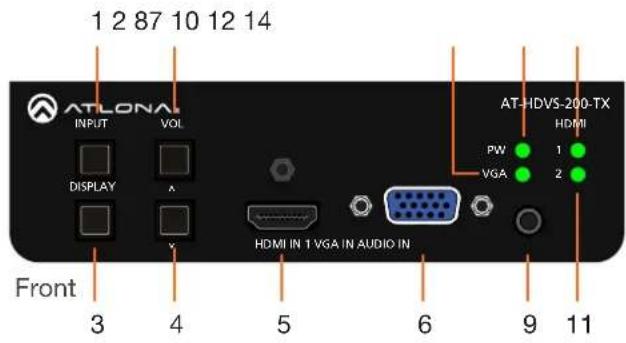
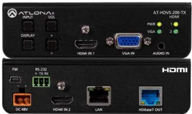
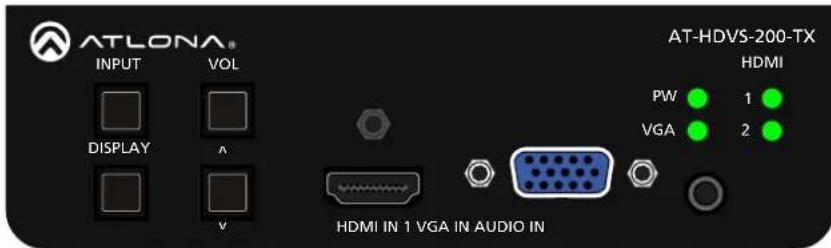
1 INPUT
Press this button to cycle through each of the available inputs: HDMI IN 1, HDMI IN 2, and VGA IN.
2 VOL (up)
Press this button to adjust the volume on the connected display. Refer to Defining the Front-Panel Buttons (page 12) for more information.
3 DISPLAY
Press this button to trigger user-defined RS-232/CEC/IP display control commands. Refer to Defining the Front-Panel Buttons (page 12) for more information.
4 VOL (down)
Press this button to adjust the volume on the connected display. Refer to Defining the Front-Panel Buttons (page 12) for more information.
5 HDMI IN 1
Connect an HDMI cable from this port to an HD source.
6 VGA IN
Connect a VGA cable from this port to a VGA source.
7 VGA
This LED indicator will glow bright green when the VGA IN port is selected.
8 PW
This LED indicator will glow bright green when the switcher is powered.
9 AUDIO IN
Connect a 3.5mm mini-stereo audio cable, from an analog audio source, to this port.
10 HDMI 1
This LED indicator will glow bright green when the HDMI IN 1 port is selected.
11 HDMI 2
This LED indicator will glow bright green when the HDMI IN 2 port is selected.
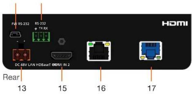
12 FW
Connect a mini USB to USB-A type cable from this port to a computer to update the firmware. Refer to Updating the Firmware (page 35) for more information.
13 DC 48V
Connect the power supply to this port to power an HDBaseT receiver, projector, or other PoE device.

NOTE: The DC 48V port is only available on the AT-HDVS-200-TX-PSK.
14 RS-232
Connect the included 3-pin Phoenix block from this connector to an RS-232 control device.
15 HDMI IN 2
Connect an HDMI cable from this port to an HD source.
16 LAN
Connect an Ethernet cable from this port to the network.
17 HDBaseT OUT
Use an Ethernet cable to connect an HDBaseT PoE receiver to this port.
Installation
RS-232 Connector
The AT-HDVS-200-TX provides RS-232 control between an automation system and an RS-232 device. This step is optional.
- Use wire strippers to remove a portion of the cable jacket.
-
Remove at least 3/16" (5 mm) from the insulation of the RX, TX, and GND wires.
-
Insert the TX, RX, and GND wires into correct terminal on the included Phoenix block. If using non-tinned stranded wire, presss the orange tab, above the terminal, while inserting the exposed wire. Repeat this step for the TX, RX, and GND connections.

natural_image
Green 3D mechanical component with three circular holes (no text or symbols)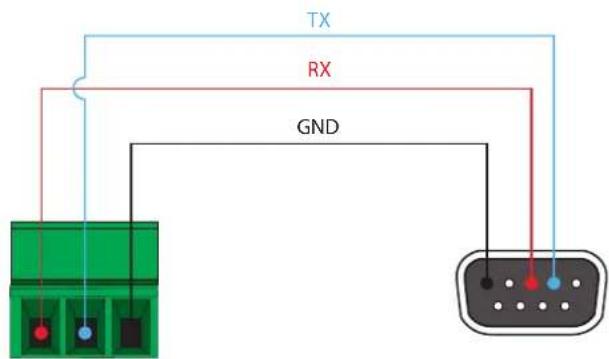
Connection Instructions
AT-HDVS-200-TX / AT-HDVS-200-TX-PSK
- Connect an HDMI cable between the HD source and the HDMI IN 1 port on the switcher.
- Connect another HDMI cable between another HD source and the HDMI IN 2 port on the switcher.
- Connect a VGA cable from a VGA source to the VGA IN port on the switcher.
- Connect a 3.5 mm mini-stereo cable from the AUDIO IN port on the switcher to the analog audio source. The AT-HDVS-200-TX can pass audio either with or without a video signal. Refer to the Audio Freerun Status option under the Audio page (page 19).
- Connect an Ethernet cable, up to 330 feet (100 meters), from the LAN port on the switcher to a Local Area Network (LAN). Refer to the System page (page 28) for information on switching between DHCP and static IP modes.

IMPORTANT: If EZ RJ-45 connectors are being used to terminate Ethernet cable, make sure that each twisted pair does not extend beyond the RJ-45 connector. Exposed twisted-pair wires may cause a short when connected to the LAN port.
-
Connect an Ethernet cable, up to 230 feet (70 meters), from the HDBaseT OUT port on the switcher to a PoE-compatible transmitter (not included). Ethernet cables should use EIA/TIA-568B termination.
-
OPTIONAL: Connect an RS-232 control device to the RS-232 port on the switcher. This port is used to control functions of the AT-HDVS-200-TX, such as volume up/down, display on/off, etc.
No power supply is required for the AT-HDVS-200-TX. This unit will be powered over the Ethernet cable, from an HDBaseT receiver.
AT-HDVS-200-TX-PSK Only
-
Connect the included power supply to the DC 48V port. Powering the AT-HDVS-200-TX-PSK will provide power to other HDBaseT receivers or projectors that require power.
-
Connect the power supply to an available AC outlet.
Connection Diagram
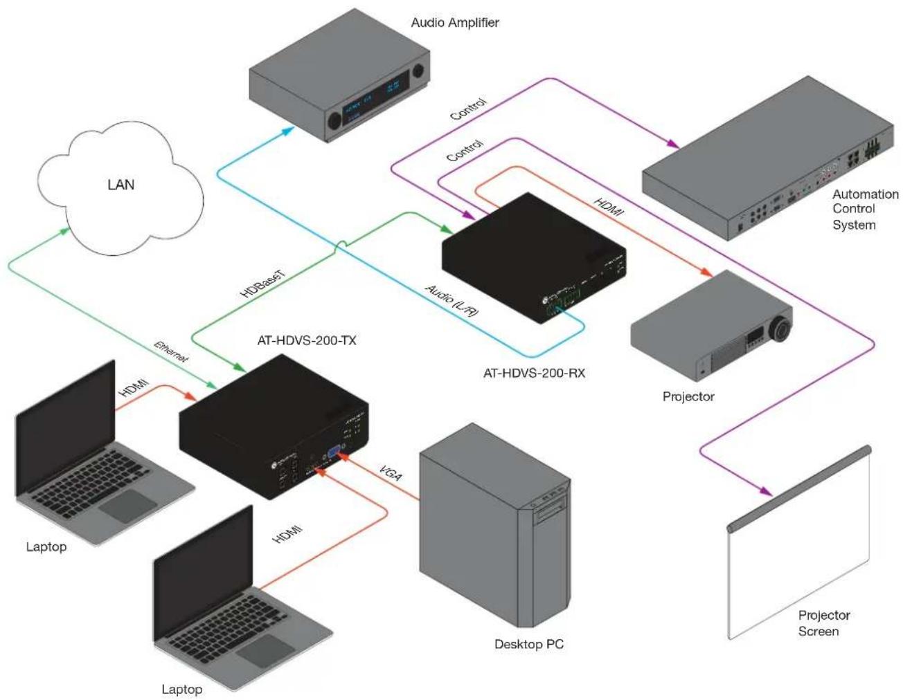
flowchart
graph TD
    LAN["LAN"] -->|Ethernet| AT_HDVS-200-TX["AT-HDVS-200-TX"]
    LAN -->|HDBaseT| AT_HDVS-200-RX["AT-HDVS-200-RX"]
    AT_HDVS-200-TX -->|HDMI| Laptop1["Laptop"]
    AT_HDVS-200-TX -->|VGA| Laptop2["Laptop"]
    AT_HDVS-200-TX -->|Control| AudioAmplifier["Audio Amplifier"]
    AT_HDVS-200-TX -->|Control| AudioAmplifier
    AT_HDVS-200-TX -->|HDMI| AudioAmplifier
    AT_HDVS-200-TX -->|Control| AutomationControlSystem["Automation Control System"]
    AT_HDVS-200-TX -->|Control| AutomationControlSystem
    AT_HDVS-200-TX -->|Control| AutomationControlSystem
    AT_HDVS-200-TX --> AudioLFL["Audio LFL"]
    AT_HDVS-200-TX --> AudioLFL
    AT_HDVS-200-TX --> AudioLFL
    AT_HDVS-200-TX --> AudioLFL
    AT_HDVS-200-TX --> AudioLFL
    AT_HDVS-200-TX --> AudioLFL
    AT_HDVS-200-TX --> AudioLFL
    AT_HDVS-200-TX --> AudioLFL
    AT_HdVS-200-RX["AT-HDVS-200-RX"]
    AT_HdVS-200-RX -->|Control| AudioAmplifier
    AT_HdVS-200-RX -->|Control| AudioLFL
    AT_HdVS-200-RX -->|Control| AudioLFL
    AT_HdVS-200-RX -->|Control| AutomationControlSystem["Automation Control System"]
    AT_HdVS-200-RX -->|Control| Projector["Projector"]
    AT_HdVS-200-RX -->|Control| Projector
    AT_HdVS-200-RX -->|Control| Projector
    AT_HdVS-200-RX --> ProjectorScreen["Projector Screen"]
IP Configuration
The AT-HDVS-200-TX is shipped with DHCP enabled. Once connected to a network, the DHCP server (if available), will automatically assign an IP address to the unit. Use an IP scanner, along with the MAC address on the bottom of the unit, to identify both the unit and its IP address on the network. If a static IP address is desired, the unit can be switched to static IP mode. Use one of the following procedures to switch between DHCP and static IP mode. The default static IP address of the AT-HDVS-200-TX is 192.168.1.254.
Using the Front Panel
- Make sure the AT-HDVS-200-TX is powered.
- Press and hold the INPUT button for approximately 15 seconds.
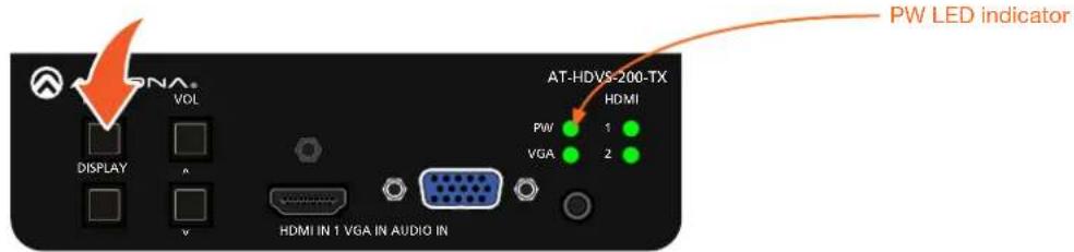
- Release the INPUT button once the PW LED indicator begins to flash. The number of flashes will indicate the currently selected IP mode.
| PW LED flashes Description | |
| Two Static IP mode | |
| Four DHCP mode |
Using Commands
Use the IPStatic and IPDHCP commands to switch between DHCP and IP mode through RS-232 or Telnet. Refer to Commands (page 3), for more information. All commands and their arguments are case-sensitive.
- Setting static IP mode
- Connect to the AT-HDVS-200-TX using RS-232 or Telnet.
- At the command line, execute the IPDHCP command using the off argument, as shown.
IPDHCP off
- Execute the IPStatic command. This command requires three arguments: the desired IP address of the AT-HDVS-200-TX, the subnet mask, and the gateway address. All arguments must be entered in dot-decimal notation. The following is an example:
IPStatic 192.168.1.112 255.255.255.0 192.168.1.1
- Setting DHCP mode
- Connect to the AT-HDVS-200-TX using RS-232 or Telnet.
- At the command line, execute the IPDHCP command using the on argument, as shown. All characters are case-sensitive.
IPDHCP on
Once DHCP is enabled, the unit will be assigned an IP address by the DHCP server (if present).
Using the Web GUI
The System page (page 28), in the web GUI, allows the AT-HDVS-200-TX to use either DHCP or static IP mode. In order to access the web GUI, the IP address of the AT-HDVS-200-TX must be known.
- Open the desired web browser and enter the IP address of the AT-HDVS-200-TX.
- Log in, using the required credentials. The factory-default username and password are listed below:
Username: root
Password: Atlona
3. Click the System tab.
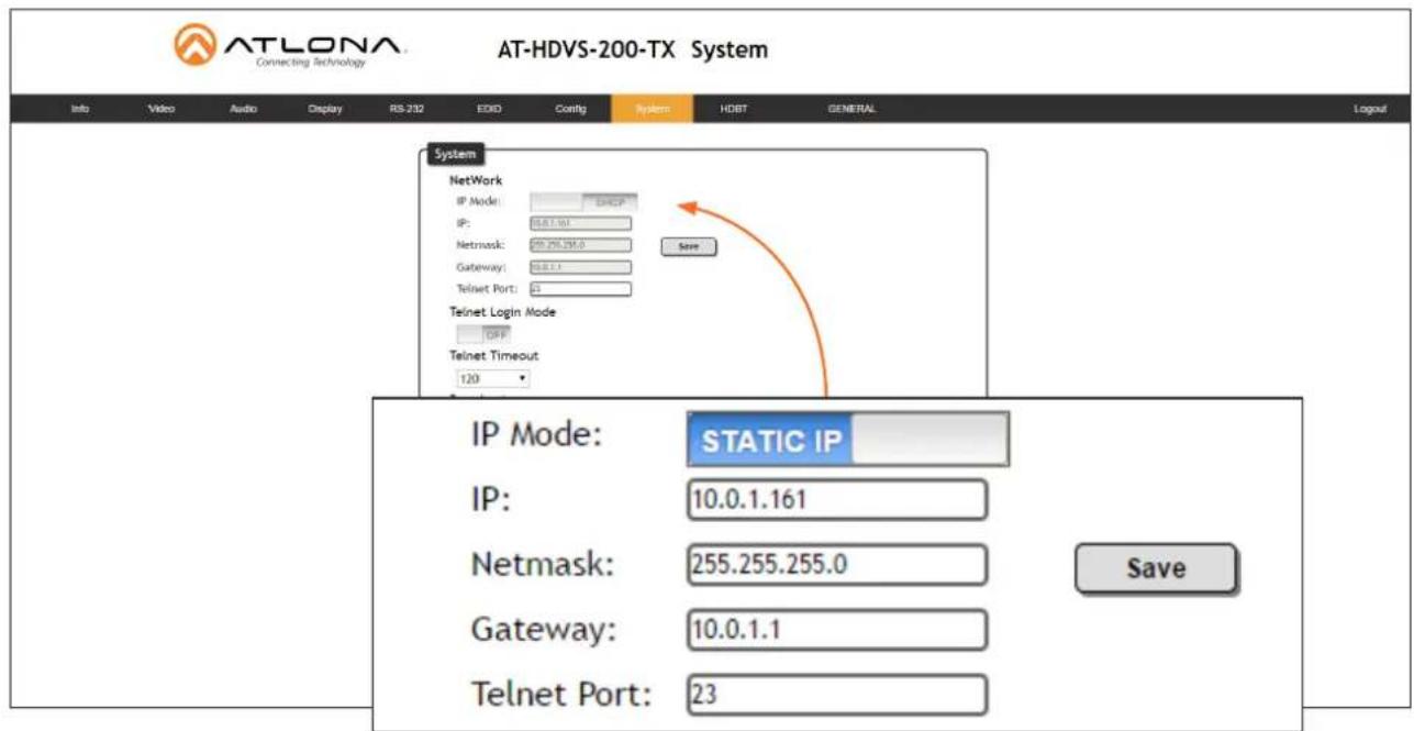
-
Click the IP Mode toggle to switch between the DHCP and STATIC IP setting.
When set to STATIC IP, the IP, Netmask, and Gateway fields can be modified. -
Click the Save button to save the changes.
Basic Operation
Defining the Front-Panel Buttons
The DISPLAY and VOL (up/dn) buttons, on the front panel, are user-defined. The factory-default setting of these buttons have no function. For example, pressing the DISPLAY button, will toggle the backlit LED on or off. This section covers how to assign a button to a function to control the display using CEC, RS-232, or IP protocols.
- Login to the web GUI. Refer to Introduction to the Web GUI (page 14) for more information, if necessary.
- Click Display in the menu bar to access the Display page.
- Scroll down to the RS-232/IP commands section. The AT-HDVS-200-TX provides the following types of display control.
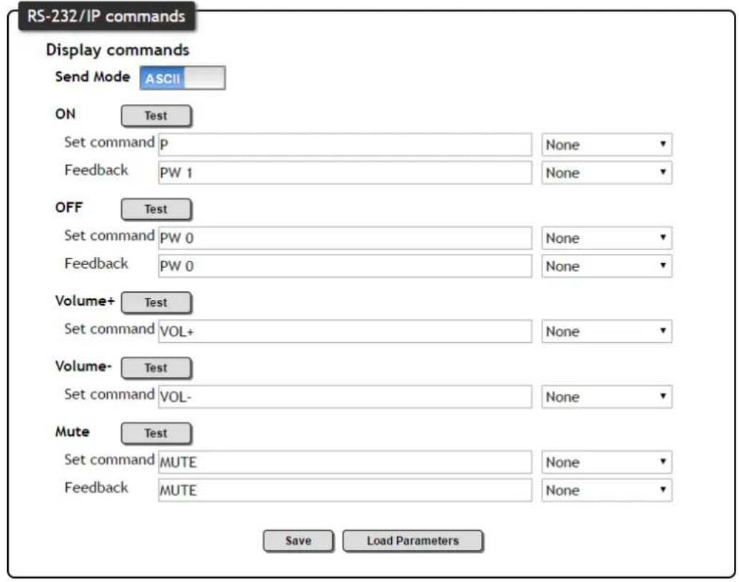
The AT-HDVS-200-TX provides the following types of display control.
| Command Description Button Used | |
| ON Power-on the display device DISPLAY | |
| OFF Power-off the display device DISPLAY | |
| Volume+ Increase the output volume of the display VOL UP | |
| Volume- Decrease the output volume of the display VOL DN | |
| Mute Mutes the audio output of the display DISPLAY or VOL buttons |
* Note that a button can only be defined for one function at a time. For example, if the DISPLAY button is already defined to turn-on or turn-off the display, this button cannot be used to mute the volume of the display device.
Basic Operation
-
Locate the command sections (ON, OFF, Volume+, Volume-, and Mute). Each command will have a Set command field.
-
Click the Send Mode toggle switch to ASCII or HEX, depending upon the format of the command.
-
Enter the required command for each function, in the Set command fields. Consult the documentation of the display device to obtain the correct command string.
-
Click the drop-down list, to the right of each Set command field, to append any required carriage return or line feed characters that may be required by the display device.
-
Enter the feedback string in the Feedback field and click the drop-down list, directly to the right to select any required characters to append to the feedback string. This step is optional.
-
Test the operation of each command by clicking the Test buttons for each command.
-
Once each command string is functioning correctly through the web GUI, test each command using the buttons on the front panel.
The Web GUI
Introduction to the Web GUI
The AT-HDVS-200-TX includes a built-in web GUI. Atlona recommends that the web GUI be used to set up the AT-HDVS-200-TX, as it provides intuitive management of all features.
The AT-HDVS-200-TX is shipped with DHCP enabled. Once connected to a network, the DHCP server will automatically assign an IP address to the unit. Use an IP scanner to determine the IP address of the AT-HDVS-200-TX. If a static IP address is desired, refer to IP Configuration (page 10). The default static IP address of the AT-HDVS-200-TX is 192.168.1.254.
- Launch a web browser.
-
In the address bar, type the IP address of the AT-HDVS-200-TX.
-
The Login page will be displayed.
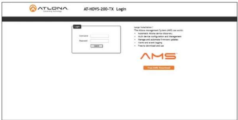
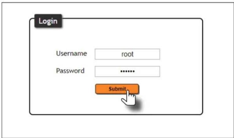
- Type root, using lower-case characters, in the Username field.
- Type Atlona in the Password field. This is the default password. The password field is case-sensitive. When the password is entered, it will be masked. The password can be changed, if desired. Refer to the Config page (page 27) for more information.
- Click the Submit button or press the ENTER key on the keyboard.
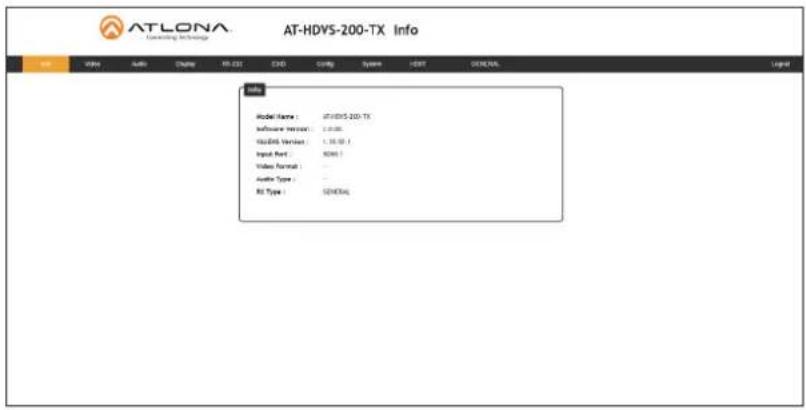
7. The Info page will be displayed.
Menu Bar
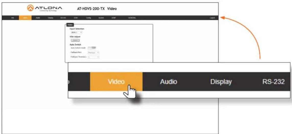
The dark-colored bar, near the top of the screen, is the menu bar. When the mouse is moved over each menu element, it will be highlighted in light orange. Once the desired menu element is highlighted, click the left mouse button to access the settings within the menu.
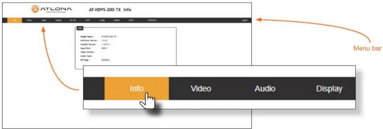
In this example, clicking Video, in the menu bar, will display the Video page.
The Web GUI
Toggles
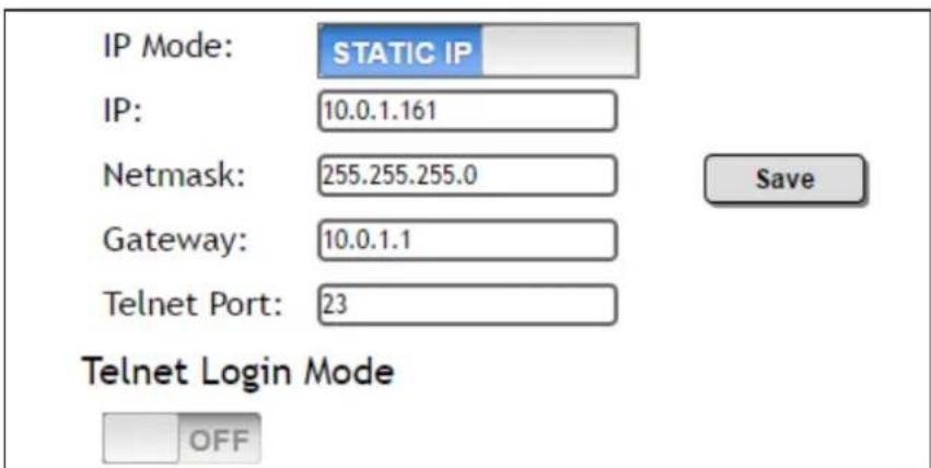
Several settings within the Web GUI use toggles, which enable, disable, or assign one of two settings. Generally, when the toggle is blue, it means that the feature is enabled or ON. If a feature is disabled, then the toggle will appear gray and be labeled as OFF. Toggle buttons may also indicate its current setting and, when enabled or set to a particular state, may also provide access to another set of controls or text fields within the Web GUI, as shown with the IP Mode toggle.
Sliders
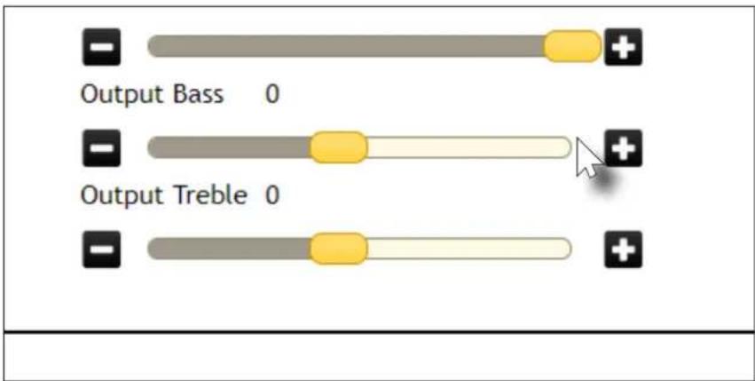
Click and drag slider controls to change their value.
Buttons
Buttons are used to execute an action or setting. Several pages within the Web GUI include a Save button. Clicking the Save button will apply and save all settings in the current page. Other buttons, such as the Factory Defaults button, under the System page, will reset the AT-HDVS-200-TX to factory-default settings.
Info page
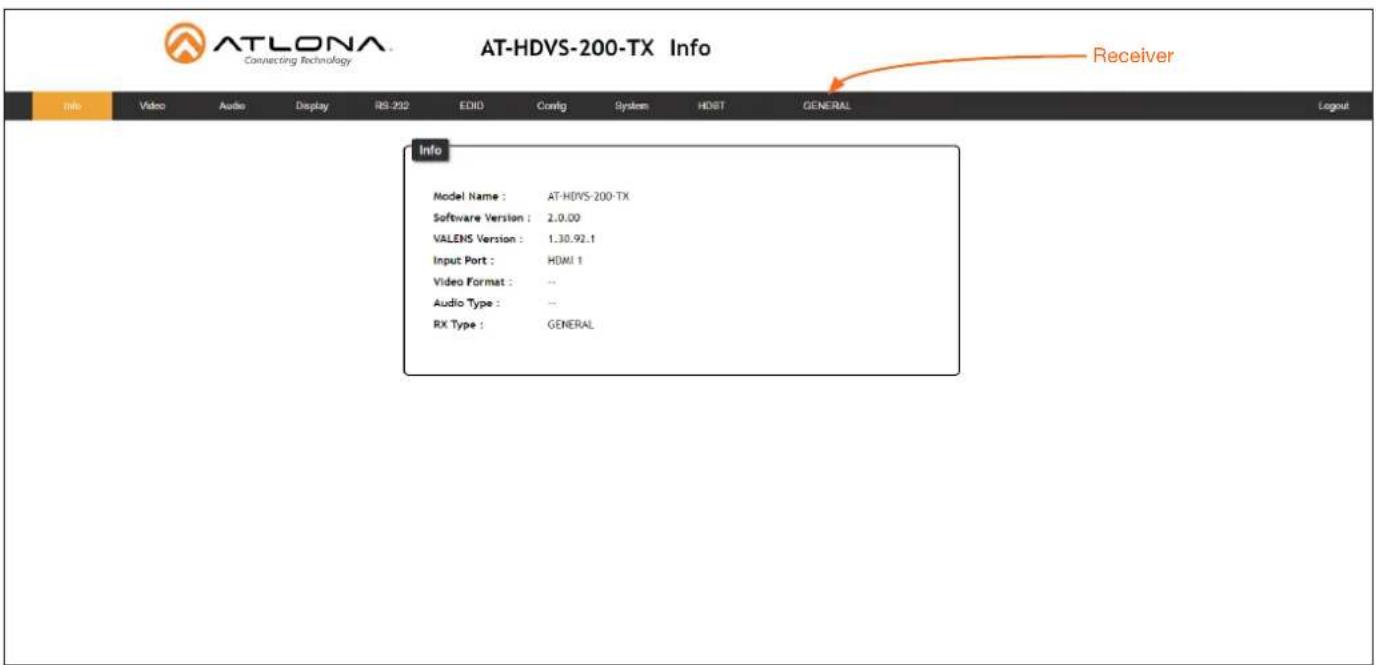
After logging in, the Info page will be displayed. The Info page provides basic information about the receiver, including the model name, software version, input video timing, and the device being using as the transmitter.
Model Name
The model SKU of this product.
Software Version
The version of firmware that the AT-HDVS-200-TX is running. Always make sure to check the AT-HDVS-200-TX product page, on the Atlona web site, for the latest version of firmware.
VALENS Version
The version of firmware used by the Valens chipset.
Video Format
Displays the input resolution of the source device.
RX Type
The model of the connected PoE-compatible receiver unit. If the AT-HDVS-200-TX is connected to a receiver, other than the AT-HDVS-200-RX, then the text "GENERAL" will be displayed here, and in the menu ribbon. However, if connected to the AT-HDVS-200-RX (using the HDBaseT port), this text will change to the name of the device and acts as a hyperlink to the AT-HDVS-200-RX web GUI. When the AT-HDVS-200-TX is connected to the AT-HDVS-200-RX, the system will be placed in kit mode. In kit mode, additional options will be available under the Video page and the RS-232 page. Refer to Kit Mode (page 31) for more information.
Video page
Input Selection
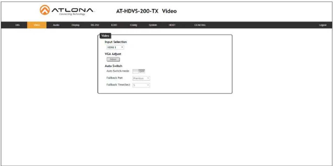
Click this drop-down list to select the desired input.
VGA Adjust
In most situations, adjustment of the VGA signal should not necessary. However, if the VGA signal does not appear correctly, click the Adjust button to automatically correct the clock and phase.
Auto Switch
Three controls are available under the Auto Switch feature.
- Click the Auto Switch mode toggle to enable or disable auto-switching.
- Click the Fallback Port drop-down list to select the fallback port. If the source is disconnected from the active port, then the switcher can be configured to automatically switch to the desired port. Click the Auto Switch mode toggle to enable or disable auto-switching.
| Setting Description | |
| HDMI 1 Automatically switches to HDMI 1. | |
| HDMI 2 Automatically switches to HDMI 2. | |
| VGA Automatically switches to VGA. | |
| Previous The switcher will return to the previous (last connected) input. If no input is found, then it will attempt to switch to a ternary port. | |
- Click the Fallback Time (Sec) drop-down list and select the time interval before the switcher attempts to search for the next port. Range: 3 to 600.
When the system is in kit mode, additional options will be available. Refer to Kit Mode (page 31) for more information.
Audio page
HDMI Audio
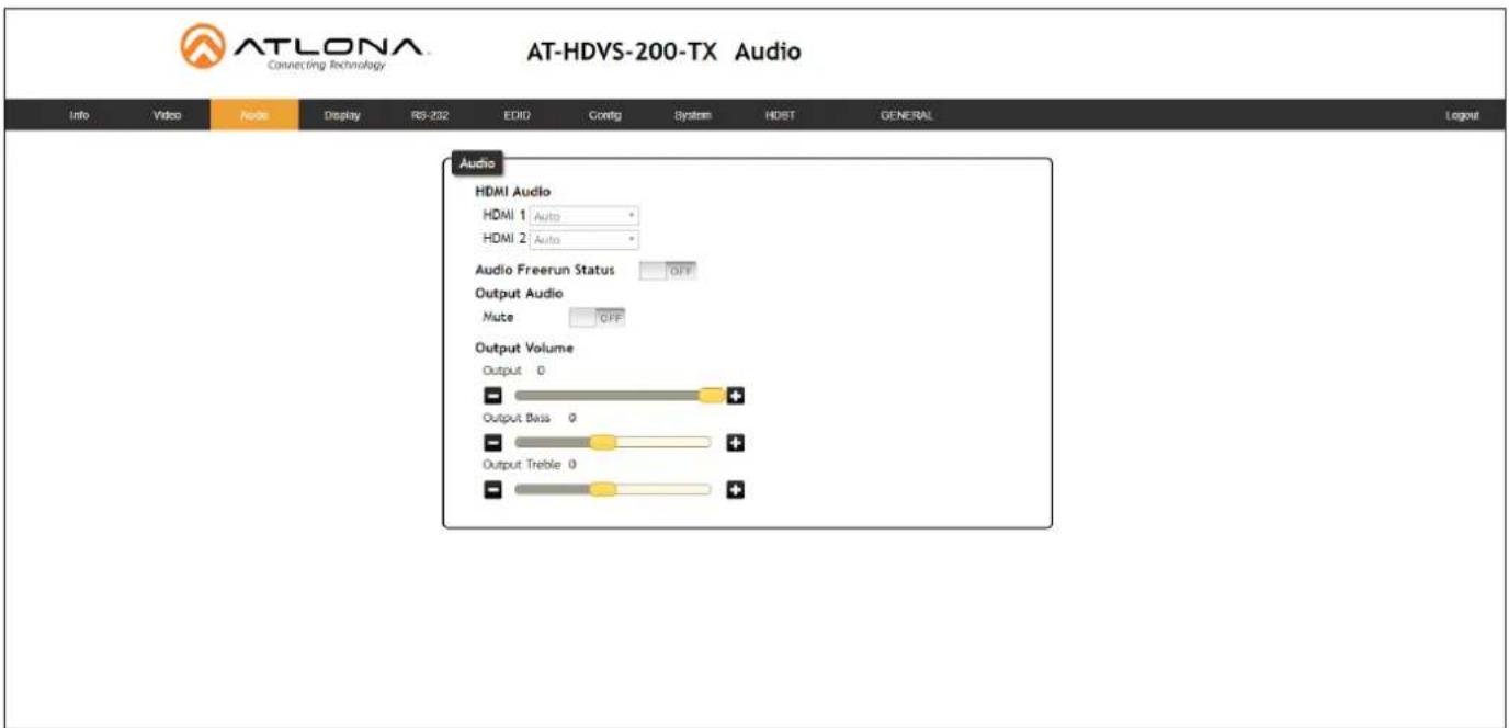
These drop-down lists are only available when the system is in kit mode. Refer to Kit Mode (page 31) for more information.
Audio Freerun Status
Audio can be passed, without the presence of a video signal. To enable this functionality, click the Audio Freerun Status toggle to the ON position. To pass both video and audio, this toggle must be set to the OFF position.

IMPORTANT: Setting the Audio Freerun Status to ON is not recommended. When set to ON, both video auto switching and display control are disabled.
Mute
Click this toggle to the OFF position to mute all audio on the output.
HDMI Audio
Click this toggle to the OFF position to mute only the HDMI audio.
Output
Click and drag this slider bar to adjust the output audio volume. Range: -80 to 0.
Output Bass
Click and drag this slider bar to adjust the bass of the audio output. Range: -12 to 15.
Output Treble
Click and drag this slider bar to adjust the treble of the audio output. Range: -12 to 15.
The Web GUI
L/R Audio
Click this toggle to the OFF position to mute only the analog audio.
Output
Click and drag this slider bar to adjust the output audio volume. Range: -80 to 0.
Output Bass
Click and drag this slider bar to adjust the bass of the audio output. Range: -12 to 15.
Output Treble
Click and drag this slider bar to adjust the treble of the audio output. Range: -12 to 15.
Display page
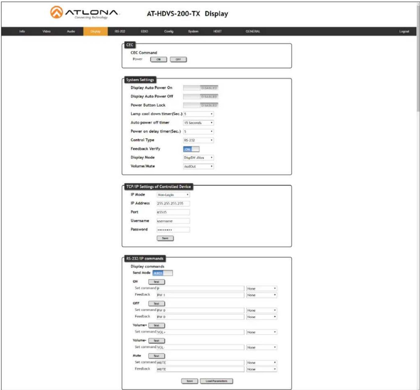
CEC
CEC Command
Click the ON button to send the power-on command to the display device. Click the OFF button to toggle the power state to off.
Consumer Electronics Control (CEC): Atlona has confirmed proper CEC functionality with several current models of Samsung, Panasonic, and Sony displays. However, it is not guaranteed that CEC will work with all displays. Many manufacturers do not support the CEC “off” command, and older displays use proprietary commands. Atlona only supports displays that use the CEC command structure defined in HDMI 1.2a. It is recommended that dealers request an evaluation product from Atlona, before designing a system using the CEC protocol. If this is not possible, then other control methods will need to be considered, in order to control displays using Atlona products.
The Web GUI
System Settings
Display Auto Power On
Sends the command to power-on the display when an A/V signal is detected. Click the toggle to enable or disable this feature. Otherwise, set to DISABLED.
Display Auto Power Off
Sends the command to power-off the display when an A/V signal is no longer present. Click the toggle to enable or disable this feature. Otherwise, set to DISABLED.
Power Button Lock
Allows the DISPLAY button, on the front panel, to be locked, preventing accidental operation when the product is in use. Click the toggle to enable or disable this feature.
Lamp Cool Down Timer
Sets the cool-down interval, in seconds, before the projector can be powered-off. During this time interval, the projector will not accept any commands until the "power off" command has been processed and the projector lamp has completed the cool-down cycle. Range: 0 to 300.
Display Warm Up Timer
Sets the time interval, in seconds, between when the display is powered on and when the DISPLAY button, on the front panel, will be locked. Range: 0 to 300.
Auto Power Off Timer
Sets the time interval, in seconds, between when the loss of A/V signal is detected and when the "Display Off" command is sent. Range: 5 seconds to 1 hour.
Control Type
Sets the control method for sending commands. The following options are available: RS-232, IP, CEC.
| Setting Description | |
| RS-232 RS-232 is used to send commands. | |
| IP Commands are sent over IP. | |
| CEC Uses CEC to send commands. | |
Feedback Verify
Sets the feedback verification state. Click the toggle to enable or disable this feature. The following options are available.
| Setting Description | |
| On This is the default setting. | The AT-HDVS-200-TX will make four attempts to send the command, if the feedback string is not acknowledged. After the fourth attempt, the process will fail. |
| Off Sends the command and ignores the feedback string. | |
The Web GUI
Display Mode
Click this drop-down list to select the display mode.
| Setting Description | |
| DispSW AVon Display switches | on/off, source audio/video signal always on. |
| DispSW AVSW Display switches | on/off, source audio/video signal switches on/off. |
| AV SW Display is always on, source audio/video signal switches on/off | |
Volume / Mute
Click this drop-down list to select the control method for volume and muting.
| Setting Description | |
| AudOut Volume and mute buttons will control volume level of the output. | |
| RS-232 Volume/Mute buttons will send the commands using RS-232 to compatible extenders and displays. | |
| IP Volume/Mute buttons will send the commands over Ethernet using the LAN connection. | |
TCP/IP Settings of Controlled Devices
IP Mode
Click this drop-down list to select the login mode.
| Setting Description | |
| Non-login Does not require a username and password when using TCP/IP to control the display. | |
| RS-232 Requires a username and password to control the display through TCP/IP. | |
IP Address
Enter the IP address of the device in this field.
Port
Enter the listening port of the device in this field.
Username
Enter the username for login. If the IP Mode is set to Non-Login, then this information will not be required.
Password
Enter the password for login. If the IP Mode is set to Non-Login, then this information will not be required.
Save
Click this button to save all changes in this window group.
The Web GUI
RS-232 / IP Commands
Send Mode
Sets the type of commands that are sent to the display, either ASCII or Hex.
On/Off/Volume+/Volume-/Mute
- Set command
Enter the command in this field.
- Feedback
Enter the feedback string in this field.
- CR-LF
Click this drop-down list to select the desired end-of-line characters to be sent.
- Test
Click this button to test the command line and/or feedback.
| Setting Description | |
| None No end-of-line characters included | |
| CR Carriage return | |
| LF Line feed | |
| CR-LF Carriage return + Line feed | |
| Space Space character | |
| STX Start-of-text character | |
| ETX End-of-text character | |
| Null Null character (binary zero) | |
Save
Click this button to save all changes in this window group.
RS-232 page
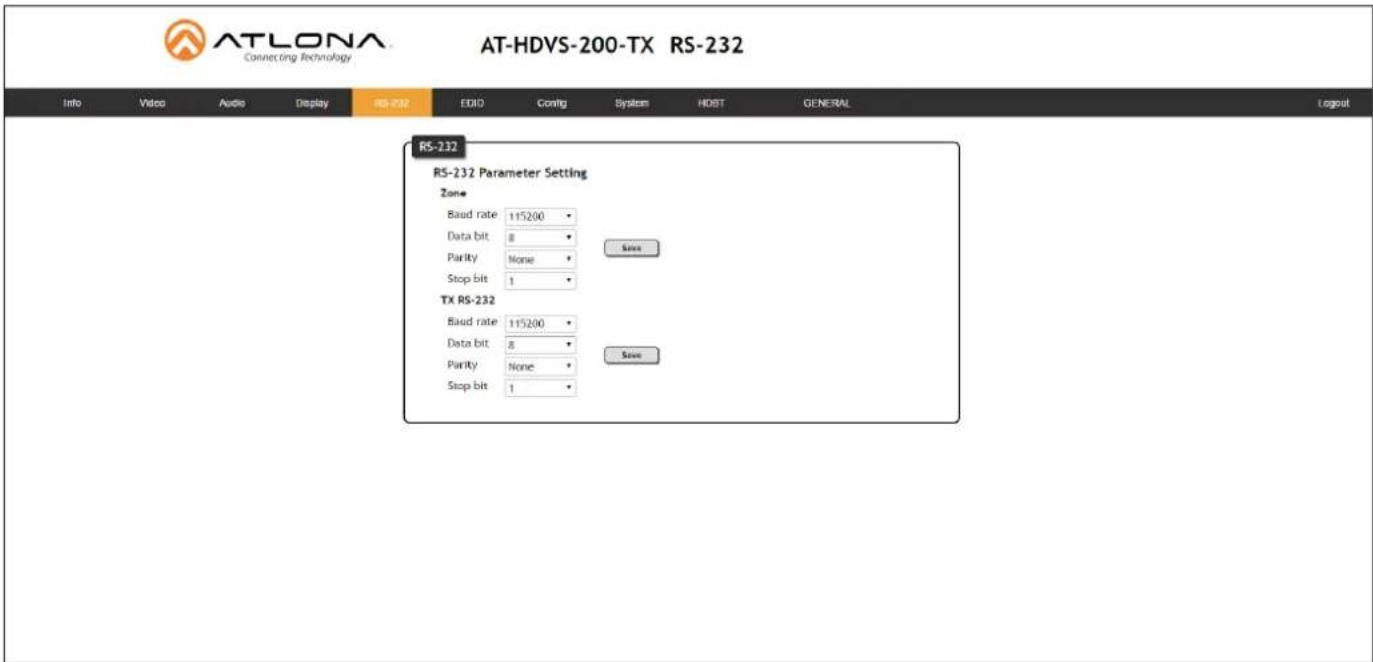
Zone
When the AT-HDVS-200-TX is connected to the AT-HDVS-200-RX, the system is placed in kit mode. In this mode, the drop-down list boxes will be disabled and the HDBaseT baud rate will be locked at 115200.
If the AT-HDVS-200-TX is connected to another HDBaseT device, such as the AT-UHD-CLSO-824, each of these drop-down list boxes can be set to the baud rate of the HDBaseT RS-232 settings on the corresponding device.
TX RS-232
The RS-232 settings of the RS-232 port on the AT-HDVS-200-TX. Click the Save button to save the settings.
| Setting Description | |
| Baud rate Sets the baud rate. | The following options are available: 2400, 9600, 19200, 38400, 56000, 57600, 115200. |
| Data bit Sets the number of data bits used to represent each character of data. The following options are available: 7 or 8. | |
| Parity Sets the parity bit, which can be included with each character to detect errors during the transmission of data. The following options are available: None, Odd, or Even. | |
| Stop bit Sets the stop bit. Stop bits are sent at the end of each character, allowing the client to detect the end of a character stream. The following options are available: 1 or 2. | |
EDID page
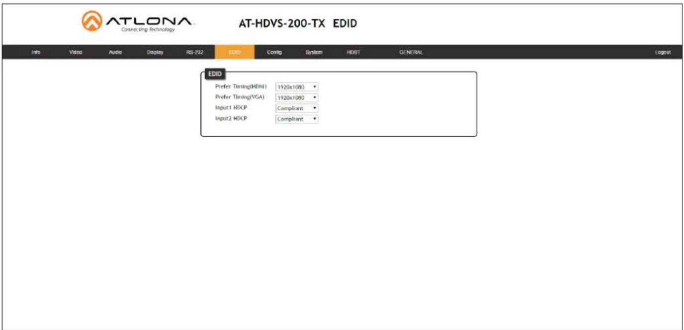
Perfer Timing (HDMI)
Click this drop-down list to select the preferred timing for the HDMI signal.
Prefer Timing (VGA)
Click this drop-down list to select the preferred timing for the VGA signal.
Input1 HDCP / Input2 HDCP
Provides control over the transmission of HDCP content for the HDMI IN 1 and HDMI IN 2 ports. The following options are available:
- Compliant - Forces detection of HDCP-compliant sink devices. If the sink device is not HDCP-compliant, then no content will be transmitted.
- Noncompliant - Suppresses detection of HDCP-compliant sink devices, allowing non-HDCP content to be transmitted.
- Auto - Automatically detects the presence of HDCP-compliant sink devices. If an HDCP-compliant display is detected, then HDCP content will be sent. Otherwise, non-HDCP content will be sent.

NOTE: The HDCP control feature does not provide decryption of HDCP content to non-HDCP sink devices.
Config page

ATLONA Connecting Technology
AT-HDVS-200-TX Config
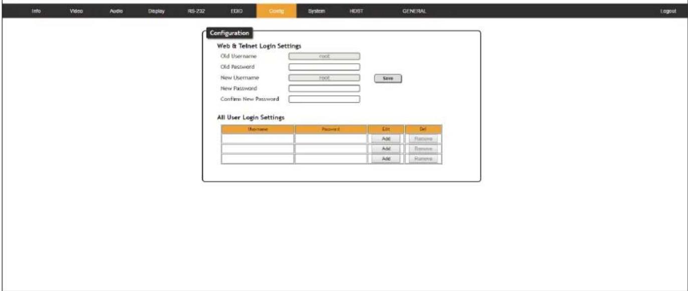
Old Username
This field cannot be changed. "root" is the administrator user.
Old Password
Enter the current password for the "root" username in this field. The default password is "Atlona".
New Username
This field cannot be changed.
Save
Click this button to save all changes.
New Password
Enter the new password fro the "root" username in this field.
Confirm New Password
Verify the new password by retyping it in this field.
All User Login Settings
- Username
Displays the username.
- Password
Displays the password for the associated username.
- Edit
Click the Add button, in this column, to edit the username and password in the row.
• Del
Click the Remove button to delete the user in the row. This button will only be available if a username and password have been created.
System page
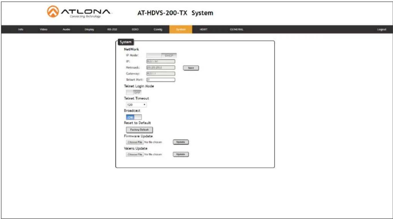
IP Mode
Click this toggle to set the IP mode of the AT-HDVS-200-TX. By default, the AT-HDVS-200-TX is set to DHCP mode. Available settings: STATIC IP, DHCP.
IP
Enter the IP address of the AT-HDVS-200-TX in this field. This field will only be available if IP Mode is set to STATIC IP. The default IP address is 192.168.1.254.
Netmask
Enter the subnet mask in this field. This field will only be available if IP Mode is set to STATIC IP.
Gateway
Enter the gateway (router) address in this field. This field will only be available if IP Mode is set to STATIC IP.
Telnet Port
Enter the Telnet port in this field.
Telnet Login Mode
Click this toggle to set the login mode to ON or OFF. If this feature is set to ON, then the AT-HDVS-200-TX will prompt for both the username and password. Use the same credentials as the web GUI.
Telnet Timeout
Click this drop-down list to select the timeout interval, in seconds, before the Telnet connection is automatically closed after no activity. Range: 1 to 3600 (seconds).
Broadcast
By default, broadcast mode is set to off. When set to on, changes in the web GUI will also be affected on the control system (if connected), via TCP/IP. To separate control between web GUI and Telnet, set this feature off.
The Web GUI
Reset to Default
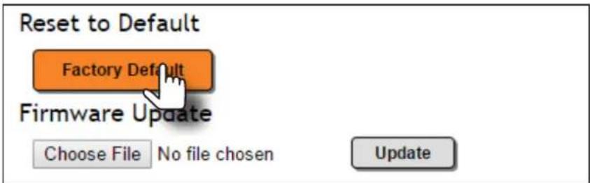
Click the Factory Default button to set the AT-HDVS-200-TX to factory-default settings.
Firmware Update
Click the Choose File button to select the firmware file, when upgrading the firmware on the AT-HDVS-200-TX. Once the firmware file is selected, click the Update button. Refer to Updating the Firmware (page 35) for more information.
Valens Update
Click the Choose File button to select the Valens firmware file, when upgrading the Valens chip on the AT-HDVS-200-TX. Once the firmware file is selected, click the Update button.
HDBT page

ATLONA Connecting Technology
AT-HDVS-200-TX HDBT
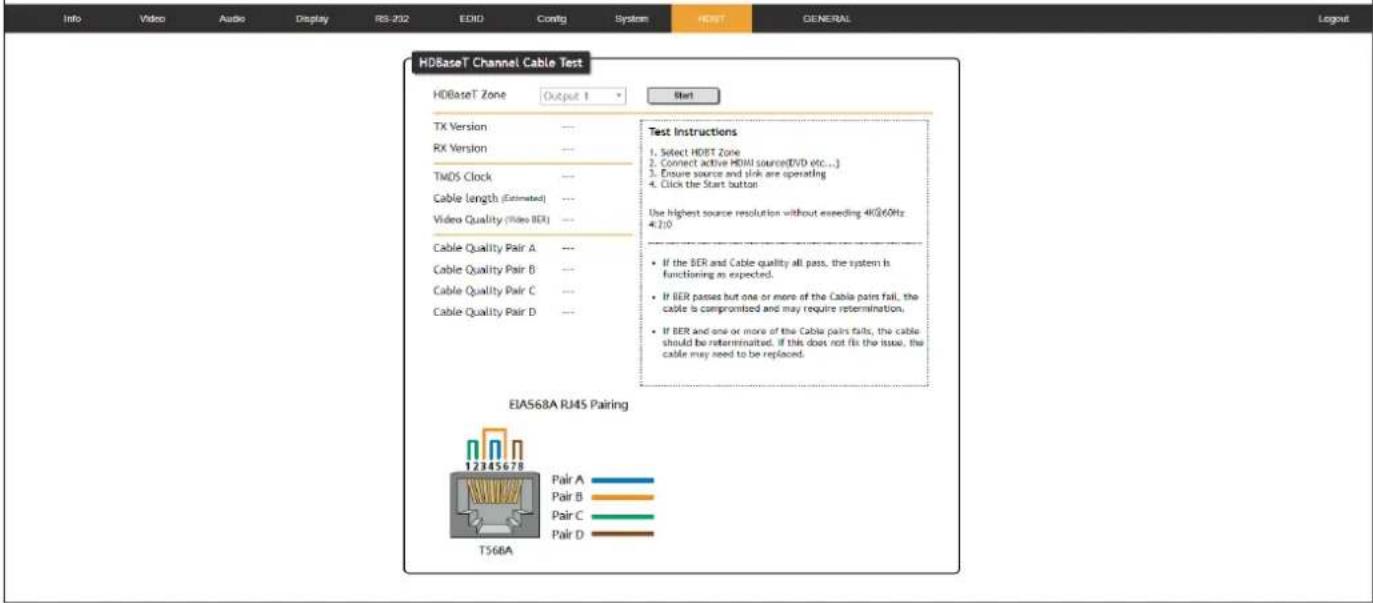
HDBaseT Channel
The AT-HDVS-200-TX has only a single HDBaseT output. Therefore, this drop-down list is disabled.
Start / Stop
Click the Start button to being the HDBaseT testing. During testing, the button text will change to "Stop". Click the Stop button to halt the HDBaseT testing process.
TX Version
The version of the Valens chip on the transmitter.
RX Version
The version of the Valens chip on the receiver.
TMDS Clock
Displays the pixel clock speed. If no source is connected, then this field will display as "None".
Cable length (Estimated)
This field indicates the approximate length of the Ethernet cable connected between the HDBaseT ports on the transmitter and the receiver. If the cable length is less than 15 feet, then this value will be displayed as 0 (zero).
Video Quality (Video BER)
The Bit Error Rate (BER). This field displays either PASS or FAIL during a test.
Cable Quality Pair (A, B, C, D)
Each of these fields will display either PASS or FAIL during a test.
Kit Mode
If the AT-HDVS-200-TX is connected to the AT-HDVS-200-TX, the system will be placed in kit mode. This section covers features only available in kit mode. Note that the text "GENERAL" has been replaced with the name of receiver (AT-HDVS-200-TX).
Video
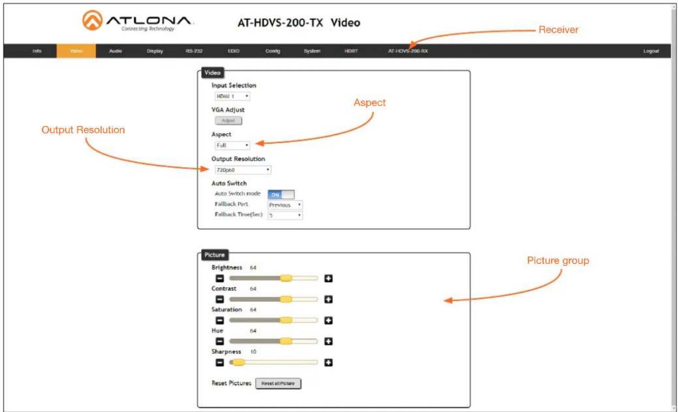
Aspect
Click the Aspect drop-down list and select the desired aspect ratio.
| Aspect Ratio Description | |
| Full The input signal is adjusted to fill the screen. | |
| 16:9 Set the aspect ratio to 16:9; common aspect ratio for HD and widescreen formats; also notated as 1:77.1 | |
| 16:10 Set the aspect ratio to 16:10; typical aspect ratio for computer and tablet displays. | |
| 4:3 Sets the aspect ratio to 4:3; if the input signal is 16:9 or 16:10, up to 30% of the vertical resolution is lost. | |
| Keep Ratio The output aspect ratio is the same as the input. | |
The Web GUI
Output Resolution
Click the Output Resolution drop-down list and select the desired resolution. The default resolution is 720p.
| Output Resolutions | |||
| 800x600@60 1024x768@60 | 1280x800@60 1280x1024@60 | ||
| 1366x768@60 1400x1050@60 | 1600x900@60RB 1600x1200@60 | ||
| 1680x1050@60 1920x1200@60RB | 720p25 720p29.97 | ||
| 720p30 720p50 720p59.94 | 720p60 | ||
| 1080i50 1080i59.94 1080i60 | 1080p23.98 | ||
| 1080p24 1080p25 1080p29.97 | 1080p30 | ||
| 1080p50 1080p59.94 1080p60 | Input | ||
| Native | |||
Brightness
Adjusts the brightness setting of the output signal. Range: 0 - 128
Contrast
Adjusts the contrast setting of the output signal. Contrast is the difference between the lightest and darkest area of an image. Range: 0 - 128
Saturation
Adjusts the color saturation of the output signal. Range: 0 - 128
Hue
Adjusts the hue of the output signal. Range: 0 - 128
Sharpness
Adjusts the sharpness of the output signal. Range: 0 - 128
Reset all Picture
Click this button to reset the above picture settings to their factory-default settings.
Audio
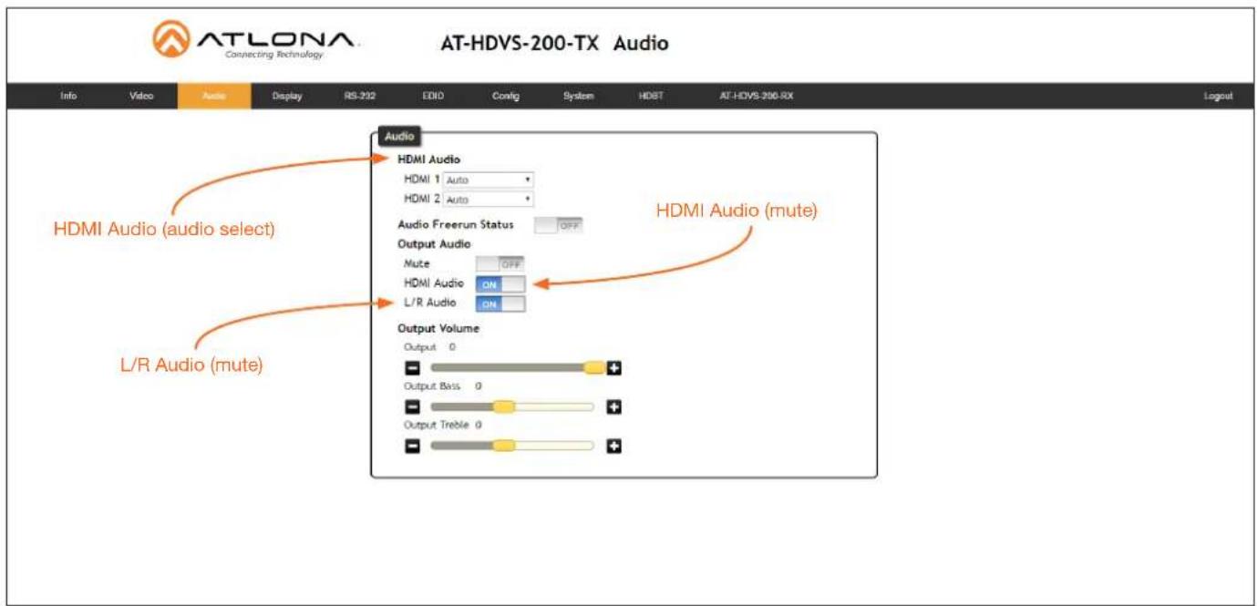
HDMI Audio
Click the drop-down list for HDMI 1 and HDMI 2 to select the input audio source used by each HDMI input.
| Setting Description | |
| Auto Automatically detects | the audio source. If an HDMI cable with embedded audio is connected, the system will use the digital audio on the HDMI cable. If a cable, which does not support audio (such as a DVI cable) is connected to the HDMI port, then the analog audio from theAUDIO INport will be used. |
| Digital The HDMI audio will | be used as the source. |
| Analog | The analog source, connected to theAUDIO INport, will be used. |
HDMI Audio
Click this toggle to the OFF position to mute only the HDMI audio.
L/R Audio
Click this toggle to the OFF position to mute all audio on the output.
RS-232
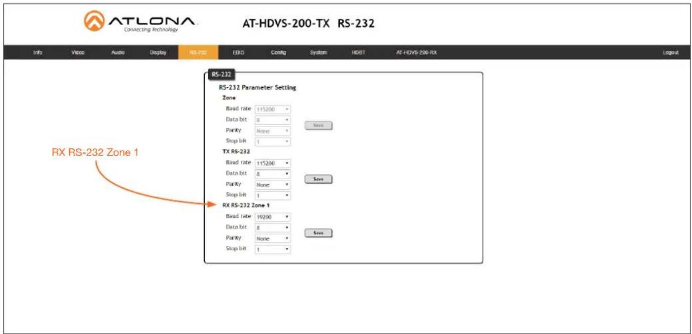
RX RS-232 Zone 1
Each of these drop-down lists refer to the setting for the RS-232 1 port on the receiver. Click the Save button to save the settings.
| Setting Description | |
| Baud rate Sets the baud rate. | The following options are available: 2400, 9600, 19200, 38400, 56000, 57600, 115200. |
| Data bit Sets the number of data bits used to represent each character of data. | The following options are available: 7 or 8. |
| Parity Sets the parity bit, which can be included with each character to detect errors during the transmission of data. | The following options are available: None, Odd, or Even. |
| Stop bit Sets the stop bit. | Stop bits are sent at the end of each character, allowing the client to detect the end of a character stream. The following options are available: 1 or 2. |

NOTE: In the illustration above, note that the Zone RS-232 settings are "locked" because the system is in kit mode.
Appendix
Updating the Firmware
Updating the firmware can be completed using either the USB interface or the web GUI. Atlona recommends using the web GUI for updating the firmware. However, if a network connection is not available, the AT-HDVS-200-TX firmware can be updated using a USB-A to USB mini-B cable
Using the Web GUI
Requirements
- AT-HDVS-200-TX
- Firmware file
-
Computer
-
Connect an Ethernet cable from the computer, containing the firmware, to the same network where the AT-HDVS-200-TX is connected.
- Go to the System page (page 28) in the web GUI.
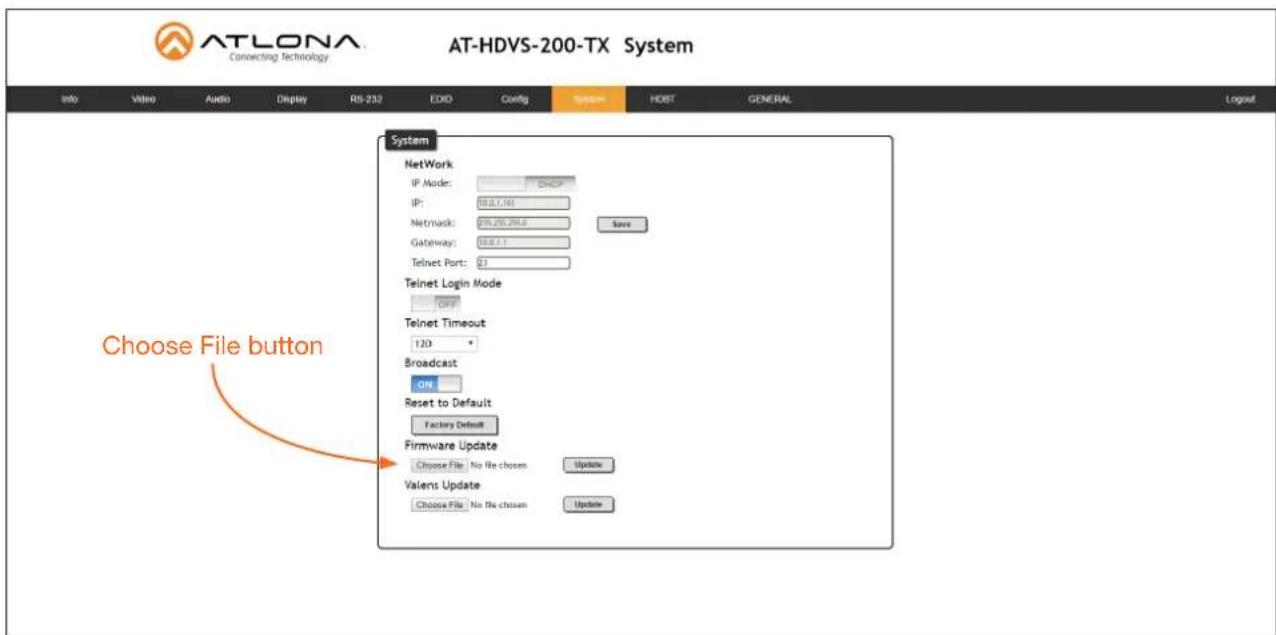
- Click the Choose File button, under the Firmware Update section.

IMPORTANT: When updating the firmware, make sure to select the Choose File button under Firmware Update. The Valens Update section does not apply to this procedure.
- Browse to the location of the firmware file, select it, and click the Open button.
- Click the Update button, under the Firmware Update section.
Appendix
- The following message box will be displayed.
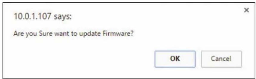
- Click the OK button to begin the firmware update process. Click the Cancel button to cancel the process.
- After the firmware update process is complete, the Login screen will be displayed.
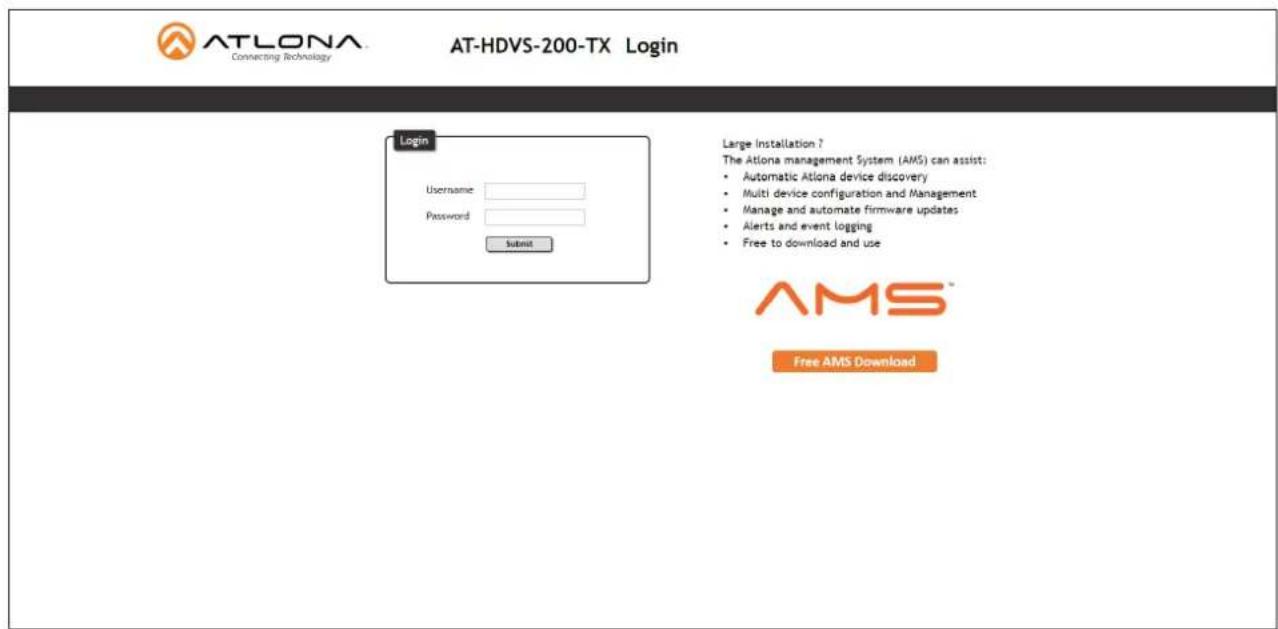
Using USB
Requirements
- AT-HDVS-200-TX
-
Firmware file
• Computer running Windows
• USB-A to USB mini-B cable -
Disconnect power from the AT-HDVS-200-TX.
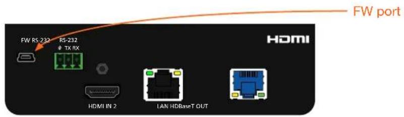
- Connect the USB-A to USB mini-B cable from the computer to the FW port on the AT-HDVS-200-TX.
Appendix
- Press and hold the INPUT button, on the front panel, while connecting power to the AT-HDVS-200-TX.
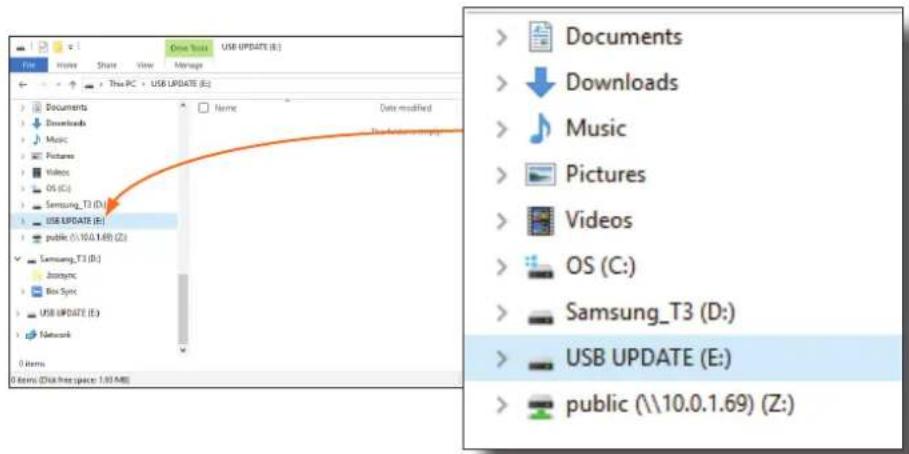
- The USB UPDATE folder will be displayed.
If this folder is not displayed, automatically, select the USB UPDATE drive from Windows Explorer.
- Delete all files from the USB UPDATE drive, if any are present.
- Drag-and-drop the firmware file to the drive.
- After the file has been copied, disconnect the USB cable from both the computer and the AT-HDVS-200-TX.
- Power-cycle the AT-HDVS-200-TX by disconnecting then reconnecting the power supply.
- The firmware update process is complete.
Default Settings
The following tables list the factory-default settings for the AT-HDVS-200-TX.
| Feature Settings | ||
| Video Input Selection | HDMI 1 | |
| Aspect | Full | |
| Auto Switch mode | OFF | |
| Fallback Port | Previous | |
| Fallback Time (Sec) | 5 | |
| Audio HDMI 1 | Auto | |
| HDMI 2 | Auto | |
| Audio Freerun Status | OFF | |
| Mute | OFF | |
| Output Volume | 0 | |
| Output Bass | 0 | |
| Output Treble | 0 | |
| Display Display Auto Power On | DISABLED | |
| Display Auto Power Off | DISABLED | |
| Power Button Lock | DISABLED | |
| Lamp cool down timer (sec) | 5 | |
| Auto power off timer (sec) | 15 | |
| Power on delay time (sec) | 5 | |
| Control Type | RS-232 | |
| Feedback Verify | ON | |
| Display Mode | DispSW AVon | |
| Volume / Mute | AudOut | |
| RS-232 Zone | 115200, 8, N, 1 | |
| TX RS-232 | 115200, 8, N, 1 | |
| EDID Prefer Timing (HDMI) | 1920x1080 | |
| Prefer Timing (VGA) | 1920x1080 | |
| Input1 HDCP | Compliant | |
| Input2 HDCP | Compliant | |
| Config Username (default) | root | |
| Password (default) | Atlona | |
| System IP Mode | DHCP | |
| Static IP Address (default) | 192.168.1.254 | |
| Netmask | 255.255.255.0 | |
| Gateway | 192.168.1.1 | |
| Telnet Port | 23 | |
| Telnet Login Mode | Off | |
| Telnet Timeout | 120 (seconds) | |
| Broadcast | On | |
Specifications
| Video | |
| HD/SD 4096×2160@24/25/30/50 | 0^*/60Hz^* , 3840×2160@24/25/30/50^*/60Hz^* , 2048×1080p , 1080p@23.98/24/25/29.97/30/50/59.94/60Hz , 1080i@50/59.94/60Hz , 720p@50/59.94/60Hz , 576p , 576i , 480p , 480i |
| VESA 2560×2048, 2560×1600, | 2048×1536 , 1920×1200 , 1680×1050 , 1600×1200 , 1600×900 , 1440×900 , 1400×1050 , 1366×768 , 1360×768 , 1280×1024 , 1280×800 1280×768 , 1152×768 , 1024×768 , 800×600 , 640×480 |
| Color Space YUV, RGB | |
| Chroma Subsampling 4:4:4, 4:2:2, 4:2:0* | |
| Color Depth 8-bit, 10-bit, 12-bit | |
| Audio | |
| Analog IN PCM 2Ch | |
| HDMI IN / HDBaseT OUT PCM | 2Ch, LPCM 5.1, LPCM 7.1, Dolby® Digital, DTS® 5.1, Dolby Digital Plus,Dolby TrueHD, DTS-HD Master AudioTM |
| Sample Rate 32 kHz, 44.1 kHz,Bit Rate 24-bit (max.) | 48 kHz, 88.2 kHz, 96 kHz, 176.4 kHz, 192 kHz |
| Resolution / Distance | 4K/UHD - Feet / Meters | 1080p - Feet / Meters | ||
| HDMI IN / OUT | 15 | 5 | 30 | 10 |
| CAT-5e / CAT-6 | 230 | 70 | 330 | 100 |
| CAT-6a / CAT-7 | 230 | 70 | 330 | 100 |
| Signal | |
| Bandwidth | 10.2 Gbps |
| CEC | Yes |
| HDCP | 1.4 |
| Temperature Fahrenheit Celsius | ||
| Operating 32 to 122 0 to 50 | ||
| Storage | -4 to 140 | -20 to 60 |
| Humidity (RH) | 20% to 90%, non-condensing | |
| Power | |
| Consumption | 12 W; 30 W (when paired) |
| BTU/h | 40.92; 102.3 |
| External Power Supply | 48 V / 0.83 W |
| Dimensions | Inches | Millimeters |
| H x W x D | 1.5 x 5 x 4.02 | 38 x 127 x 102 |
| Weight Pounds | Kilograms | |
| Device | 0.64 | 0.29 |
| Certification | ||
| Unit | CE, FCC | |
Appendix
| Compliance | ||
| NDAA-889 Yes | ||
| TAA Yes | ||
| Warranty | ||
| 3 years View the full warranty information here:https://atlona.com/warranty____ | ||
- Switcher for HDMI and VGA
- with Ethernet-Enabled HDBaseT Output
- Version Information
- Sales, Marketing, and Customer Support
- Main Office
- International Headquarters
- Operating Notes
- Warranty
- Safety and Certification
- CAUTION
- FCC Compliance
- Copyright, Trademark, and Registration
- Table of Contents
- Introduction
- Features
- Package Contents
- AT-HDVS-200-TX AT-HDVS-200-TX-PSK
- Panel Description
- INPUT
- VOL (up)
- DISPLAY
- VOL (down)
- HDMI IN 1
- VGA IN
- VGA
- PW
- AUDIO IN
- HDMI 1
- HDMI 2
- FW
- DC 48V
- RS-232
- HDMI IN 2
- LAN
- HDBaseT OUT
- Installation
- RS-232 Connector
- Connection Instructions
- AT-HDVS-200-TX / AT-HDVS-200-TX-PSK
- AT-HDVS-200-TX-PSK Only
- IP Configuration
- Using the Front Panel
- Using Commands
- - Setting static IP mode
- - Setting DHCP mode
- Using the Web GUI
- Click the System tab.
- Basic Operation
- Defining the Front-Panel Buttons
- The Web GUI
- Introduction to the Web GUI
- The Info page will be displayed.
- Menu Bar
- Toggles
- Sliders
- Buttons
- Info page
- Model Name
- Software Version
- VALENS Version
- Video Format
- RX Type
- Video page
- Input Selection
- VGA Adjust
- Auto Switch
- Audio page
- HDMI Audio
- Audio Freerun Status
- Mute
- Output
- Output Bass
- Output Treble
- L/R Audio
- Display page
- CEC
- CEC Command
- System Settings
- Display Auto Power On
- Display Auto Power Off
- Power Button Lock
- Lamp Cool Down Timer
- Display Warm Up Timer
- Auto Power Off Timer
- Control Type
- Feedback Verify
- Display Mode
- Volume / Mute
- TCP/IP Settings of Controlled Devices
- IP Mode
- IP Address
- Port
- Username
- Password
- Save
- RS-232 / IP Commands
- Send Mode
- On/Off/Volume+/Volume-/Mute
- - Set command
- - Feedback
- - CR-LF
- - Test
- RS-232 page
- Zone
- TX RS-232
- EDID page
- Perfer Timing (HDMI)
- Prefer Timing (VGA)
- Input1 HDCP / Input2 HDCP
- Config page
- Old Username
- Old Password
- New Username
- New Password
- Confirm New Password
- All User Login Settings
- System page
- IP
- Netmask
- Gateway
- Telnet Port
- Telnet Login Mode
- Telnet Timeout
- Broadcast
- Reset to Default
- Firmware Update
- Valens Update
- HDBT page
- HDBaseT Channel
- Start / Stop
- TX Version
- RX Version
- TMDS Clock
- Cable length (Estimated)
- Video Quality (Video BER)
- Cable Quality Pair (A, B, C, D)
- Kit Mode
- Aspect
- Output Resolution
- Brightness
- Contrast
- Saturation
- Hue
- Sharpness
- Reset all Picture
- RX RS-232 Zone 1
- Appendix
- Updating the Firmware
- Using USB
- Default Settings
Brand : Atlona
Model : AT-OME-RX21
Category : Audio/video converter