
AT-HDVS-150-TX-WP-UK - Audio/video converter Atlona - Free user manual and instructions
Find the device manual for free AT-HDVS-150-TX-WP-UK Atlona in PDF.


| Product Type | HDBaseT Wall Plate Transmitter |
| Brand | Atlona |
| Model | AT-HDVS-150-TX-WP-UK |
| Category | Audio/Video Converter |
| Dimensions (W x H x D) | 4.13 x 2.72 x 1.65 in (105 x 69 x 42 mm) |
| Weight | 0.55 lbs (0.25 kg) |
| Power Supply | 24V DC, 0.5A (PoE or external adapter) |
| Video Resolution | Up to 4K@60Hz (4:4:4, 8-bit) |
| HDCP Support | HDCP 2.2 |
| Transmission Distance | Up to 100m (328 ft) via CAT6 |
| Audio Support | Embedded HDMI audio, up to 7.1 channels |
| EDID Management | Built-in EDID emulation and management |
| Input Connector | 1 x HDMI (Type A female) |
| Output Connector | 1 x RJ-45 (HDBaseT) |
| Other Connectors | 1 x USB (firmware update), 1 x RS-232 (control) |
| Mounting | Wall plate (UK single-gang) |
| Operating Temperature | 32°F to 104°F (0°C to 40°C) |
| Storage Temperature | -4°F to 140°F (-20°C to 60°C) |
| Maintenance | Clean with a soft, dry cloth; avoid liquids |
| Safety | Use only supplied power adapter; do not expose to moisture |
| Spare Parts & Repairability | No user-serviceable parts; contact Atlona support for repairs |
| General Information | Compatible with Atlona AT-HDVS-150-RX receiver |
Frequently Asked Questions - AT-HDVS-150-TX-WP-UK Atlona
User questions about AT-HDVS-150-TX-WP-UK Atlona
0 question about this device. Answer the ones you know or ask your own.
Ask a new question about this device
Download the instructions for your Audio/video converter in PDF format for free! Find your manual AT-HDVS-150-TX-WP-UK - Atlona and take your electronic device back in hand. On this page are published all the documents necessary for the use of your device. AT-HDVS-150-TX-WP-UK by Atlona.
USER MANUAL AT-HDVS-150-TX-WP-UK Atlona
Wall Plate Switcher for HDMI and VGA with HDBaseT™ Output


Version Information
Version Release Date Notes
2 05/17 Updated to new manual format
Welcome to Atlona!
Thank you for purchasing this Atlona product. We hope you enjoy it and will take an extra few moments to register your new purchase.
Registration only takes a few minutes and protects this product against theft or loss. In addition, you will receive notifications of product updates and firmware. Atlona product registration is voluntary and failure to register will not affect the product warranty.
To register your product, go to http://www.atlona.com/registration
Sales, Marketing, and Customer Support
Main Office
Atlona Incorporated
70 Daggett Drive
San Jose, CA 95134
United States
Office: +1.877.536.3976 (US Toll-free)
Office: +1.408.962.0515 (US/International)
Sales and Customer Service Hours
Monday - Friday: 6:00 a.m. - 4:30 p.m. (PST)
http://www.atlona.com/
International Headquarters
Atlona International AG
Ringstrasse 15a
8600 Dübendorf
Switzerland
Office: +41 43 508 4321
Sales and Customer Service Hours
Monday - Friday: 09:00 - 17:00 (UTC +1)
Operating Notes
As of this writing, there are no firmware updates for this product. When new firmware is released, update instructions will be included with the firmware and will be appended to this manual.

IMPORTANT: Visit http://www.atlona.com/product/AT-HDVS-150-TX-WP for the latest firmware updates and User Manual.
Atlona, Inc. ("Atlona") Limited Product Warranty
Coverage
Atlona warrants its products will substantially perform to their published specifications and will be free from defects in materials and workmanship under normal use, conditions and service.
Under its Limited Product Warranty, Atlona, at its sole discretion, will either:
- repair or facilitate the repair of defective products within a reasonable period of time, restore products to their proper operating condition and return defective products free of any charge for necessary parts, labor and shipping.
OR
- replace and return, free of charge, any defective products with direct replacement or with similar products deemed by Atlona to perform substantially the same function as the original products.
OR
- refund the pro-rated value based on the remaining term of the warranty period, not to exceed MSRP, in cases where products are beyond repair and/or no direct or substantially similar replacement products exist.
Repair, replacement or refund of Atlona products is the purchaser's exclusive remedy and Atlona liability does not extend to any other damages, incidental, consequential or otherwise.
This Limited Product Warranty extends to the original end-user purchaser of Atlona products and is non-transferrable to any subsequent purchaser(s) or owner(s) of these products.
Coverage Periods
Atlona Limited Product Warranty Period begins on the date of purchase by the end-purchaser. The date contained on the end-purchaser 's sales or delivery receipt is the proof purchase date.
Limited Product Warranty Terms - New Products
• 10 years from proof of purchase date for hardware/electronics products purchased on or after June 1, 2013.
• 3 years from proof of purchase date for hardware/electronics products purchased before June 1, 2013.
• Lifetime Limited Product Warranty for all cable products.
Limited Product Warranty Terms - Refurbished (B-Stock) Products and Discontinued Products
- 3 years from proof of purchase date for all Refurbished (B-Stock) and Discontinued hardware and electronic products purchased on or after June 1, 2013.
Remedy
Atlona recommends that end-purchasers contact their authorized Atlona dealer or reseller from whom they purchased their products. Atlona can also be contacted directly. Visit atlona.com for Atlona's contact information and hours of operation. Atlona requires that a dated sales or delivery receipt from an authorized dealer, reseller or end-purchaser is provided before Atlona extends its warranty services. Additionally, a return merchandise authorization (RMA) and/or case number, is required to be obtained from Atlona in advance of returns.
Atlona requires that products returned are properly packed, preferably in the original carton, for shipping. Cartons not bearing a return authorization or case number will be refused. Atlona, at its sole discretion, reserves the right to reject any products received without advanced authorization. Authorizations can be requested by calling 1-877-536-3976 (US toll free) or 1-408-962-0515 (US/international) or via Atlona's website at atlona.com.
Exclusions
This Limited Product Warranty excludes:
- Damage, deterioration or malfunction caused by any alteration, modification, improper use, neglect, improper packaging or shipping (such claims must be presented to the carrier), lightning, power surges, or other acts of nature.
Atlona, Inc. ("Atlona") Limited Product Warranty
- Damage, deterioration or malfunction resulting from the installation or removal of this product from any installation, any unauthorized tampering with this product, any repairs attempted by anyone unauthorized by Atlona to make such repairs, or any other cause which does not relate directly to a defect in materials and/or workmanship of this product.
- Equipment enclosures, cables, power supplies, batteries, LCD displays, and any accessories used in conjunction with the product(s).
- Products purchased from unauthorized distributors, dealers, resellers, auction websites and similar unauthorized channels of distribution.
Disclaimers
This Limited Product Warranty does not imply that the electronic components contained within Atlona's products will not become obsolete nor does it imply Atlona products or their electronic components will remain compatible with any other current product, technology or any future products or technologies in which Atlona's products may be used in conjunction with. Atlona, at its sole discretion, reserves the right not to extend its warranty offering in instances arising outside its normal course of business including, but not limited to, damage inflicted to its products from acts of god.
Limitation on Liability
The maximum liability of Atlona under this limited product warranty shall not exceed the original Atlona MSRP for its products. To the maximum extent permitted by law, Atlona is not responsible for the direct, special, incidental or consequential damages resulting from any breach of warranty or condition, or under any other legal theory. Some countries, districts or states do not allow the exclusion or limitation of relief, special, incidental, consequential or indirect damages, or the limitation of liability to specified amounts, so the above limitations or exclusions may not apply to you.
Exclusive Remedy
To the maximum extent permitted by law, this limited product warranty and the remedies set forth above are exclusive and in lieu of all other warranties, remedies and conditions, whether oral or written, express or implied. To the maximum extent permitted by law, Atlona specifically disclaims all implied warranties, including, without limitation, warranties of merchantability and fitness for a particular purpose. If Atlona cannot lawfully disclaim or exclude implied warranties under applicable law, then all implied warranties covering its products including warranties of merchantability and fitness for a particular purpose, shall provide to its products under applicable law. If any product to which this limited warranty applies is a “Consumer Product” under the Magnuson-Moss Warranty Act (15 U.S.C.A. §2301, ET SEQ.) or other applicable law, the foregoing disclaimer of implied warranties shall not apply, and all implied warranties on its products, including warranties of merchantability and fitness for the particular purpose, shall apply as provided under applicable law.
Other Conditions
Atlona's Limited Product Warranty offering gives legal rights, and other rights may apply and vary from country to country or state to state. This limited warranty is void if (i) the label bearing the serial number of products have been removed or defaced, (ii) products are not purchased from an authorized Atlona dealer or reseller. A comprehensive list of Atlona's authorized distributors, dealers and resellers can be found at www.atlona.com.
Important Safety Information
CAUTION
RISK OF ELECTRIC SHOCK
DO NOT OPEN
CAUTION: TO REDUCT THE RISK OF
ELECTRIC SHOCK
DO NOT OPEN ENCLOSURE OR EXPOSE
TO RAIN OR MOISTURE
NO USER-SERVICEABLE PARTS
INSIDE REFER SERVICING TO
QUALIFIED SERVICE PERSONNEL.

The exclamation point within an equilateral triangle is intended to alert the user to the presence of important operating and maintenance instructions in the literature accompanying the product.

The information bubble is intended to alert the user to helpful or optional operational instructions in the literature accompanying the product.
- Read these instructions.
- Keep these instructions.
- Heed all warnings.
- Follow all instructions.
- Do not use this product near water.
- Clean only with a dry cloth.
- Do not block any ventilation openings. Install in accordance with the manufacturer's instructions.
-
Do not install or place this product near any heat sources such as radiators, heat registers, stoves, or other apparatus (including amplifiers) that produce heat.
-
Do not defeat the safety purpose of a polarized or grounding-type plug. A polarized plug has two blades with one wider than the other. A grounding type plug has two blades and a third grounding prong. The wide blade or the third prong are provided for your safety. If the provided plug does not fit into your outlet, consult an electrician for replacement of the obsolete outlet.
- Protect the power cord from being walked on or pinched particularly at plugs, convenience receptacles, and the point where they exit from the product.
- Only use attachments/accessories specified by Atlona.
- To reduce the risk of electric shock and/or damage to this product, never handle or touch this unit or power cord if your hands are wet or damp. Do not expose this product to rain or moisture.
- Unplug this product during lightning storms or when unused for long periods of time.
- Refer all servicing to qualified service personnel. Servicing is required when the product has been damaged in any way, such as power-supply cord or plug is damaged, liquid has been spilled or objects have fallen into the product, the product has been exposed to rain or moisture, does not operate normally, or has been dropped.


FCC Statement

FCC Compliance and Advisory Statement: This hardware device complies with Part 15 of the FCC rules. Operation is subject to the following two conditions: 1) this device may not cause harmful interference, and 2) this device must accept any interference received including interference that may cause undesired operation. This equipment has been tested and found to comply with the limits for a Class A digital device, pursuant to Part 15 of the FCC Rules. These limits are designed to provide reasonable protection against harmful interference in a commercial installation. This equipment generates, uses, and can radiate radio frequency energy and, if not installed or used in accordance with the instructions, may cause harmful interference
to radio communications. However there is no guarantee that interference will not occur in a particular installation. If this equipment does cause harmful interference to radio or television reception, which can be determined by turning the equipment off and on, the user is encouraged to try to correct the interference by one or more of the following measures: 1) reorient or relocate the receiving antenna; 2) increase the separation between the equipment and the receiver; 3) connect the equipment to an outlet on a circuit different from that to which the receiver is connected; 4) consult the dealer or an experienced radio/TV technician for help. Any changes or modifications not expressly approved by the party responsible for compliance could void the user's authority to operate the equipment. Where shielded interface cables have been provided with the product or specified additional components or accessories elsewhere defined to be used with the installation of the product, they must be used in order to ensure compliance with FCC regulations.
Table of Contents
Introduction 8
Features 8
Package Contents 8
Panel Description 9
Installation 10
Connection Instructions 10
Connection Diagram 11
Basic Operation 12
Powering the Display 12
Selecting the Input 12
Auto Switching 13
Passing Analog Audio 13
Appendix 14
Updating the Firmware 14
Specifications 16
Index 18
Introduction
The Atlona AT-HDVS-150-TX-WP is a 2×1 switcher and HDBaseT transmitter with an HDMI input plus a VGA input with audio. The HDVS-150-TX-WP features a US two-gang wall plate form factor. Video signals up to 1080p, plus embedded audio can be transmitted up to 230 feet (70 meters). The HDVS-150-TX-WP is designed for use with the AT-HDVS-150-RX receiver and HD scaler, and can serve as the central component of a compact, automated AV system with the convenience of automatic input selection and display control. The switcher is remotely powered by the HDVS-150-RX through Power over Ethernet (PoE).
Features
- Extends AV up to 230 feet (70 meters) @ 1080p or 1920×1200.
• Transmits AV up to 230 feet (70 meters) @ 1080p or 130 feet (40 meters) @ 4K/UHD* using CAT6a/7 cable.
• HDMI input plus a VGA input with audio. - Allows advanced HDMI display devices to be used with legacy VGA sources
• Power for transmitter is supplied by AT-HDVS-150-RX over HDBaseT. - Shallow, 1.5 inch (40 mm) deep enclosure and recessed RJ-45 connector simplify integration.
- Selects active input when sources are connected or if there is a change in source power status.
• LED indicators provide power and input selection status information
• USB port provides an easy means for device updates.
Package Contents
1 x AT-HDVS-150-TX-WP
1 x Wall plate covers (US)
4 x US wall plate screws
2 x UK wall plate screws
1 x Installation guide
Panel Description

1 INPUT SELECT
Press this button to switch between HDMI IN and VGA IN port. By default, HDMI IN is selected port. This button will glow bright blue when the wall plate is powered.
2 DISPLAY ON/OFF
Press this button to power-on the display (connected to the receiver), place it in standby mode, or control a connected display using the HDBaseT output.
3 LINK
This LED indicator will glow bright amber when a powered link exists between the AT-HDVS-150-TX-WP and a compatible receiver, such as the AT-HDVS-150-RX.
4 HDMI IN
Connect an HDMI cable from this port to an HD source.
5 AUDIO IN
Connect a 3.5mm mini-stereo audio cable, from an analog audio source, to this port. See Passing Analog Audio (page 13) for more information.
6 VGA IN
Connect a VGA cable from this port to a VGA source.
7 HDBaseT OUT
Connect an Ethernet cable from this port to a compatible HDBaseT receiver, such as an AT-HDVS-150-RX.
Installation
Connection Instructions

NOTE: Although the wall installation of the US and UK version will differ, the following connection instructions apply to both the AT-HDVS-150-TX-WP and AT-HDVS-150-TX-WP-UK.
- Connect an Ethernet cable, up to 230 feet (70 meters), from the HDBaseT OUT port, on the back of the wall plate, to an HDBaseT-compatible receiver (not included). Ethernet cables should use EIA/TIA-568B termination.
-
Assemble the AT-HDVS-150-TX-WP to the 2-gang electrical box or mud ring using the included screws. When installing into an electrical box, the depth of the box must provide at least 40 millimeters of clearance.
-
US version
Secure the wall plate with the four (included) shorter screws. -
UK version
Secure the wall plate with the two (included) longer screws. -
Connect an HDMI cable from the HD source to the HDMI IN port on the wall plate.
-
Connect a VGA cable from a VGA source to the VGA IN port on the wall plate.
-
Connect a 3.5 mm mini-stereo cable from the AUDIO IN port on the switcher to the analog audio source. This port allows two-channel analog audio to be included when the VGA IN port is selected. Refer to Passing Analog Audio (page 13) for more information.
No power supply is required for the AT-HDVS-150-TX-WP. This unit will be powered over the Ethernet cable, from an HDBaseT receiver.
Connection Diagram

NOTE: Although the wall installation of the US and UK version will differ, the following connection diagram applies to both the AT-HDVS-150-TX-WP and AT-HDVS-150-TX-WP-UK.
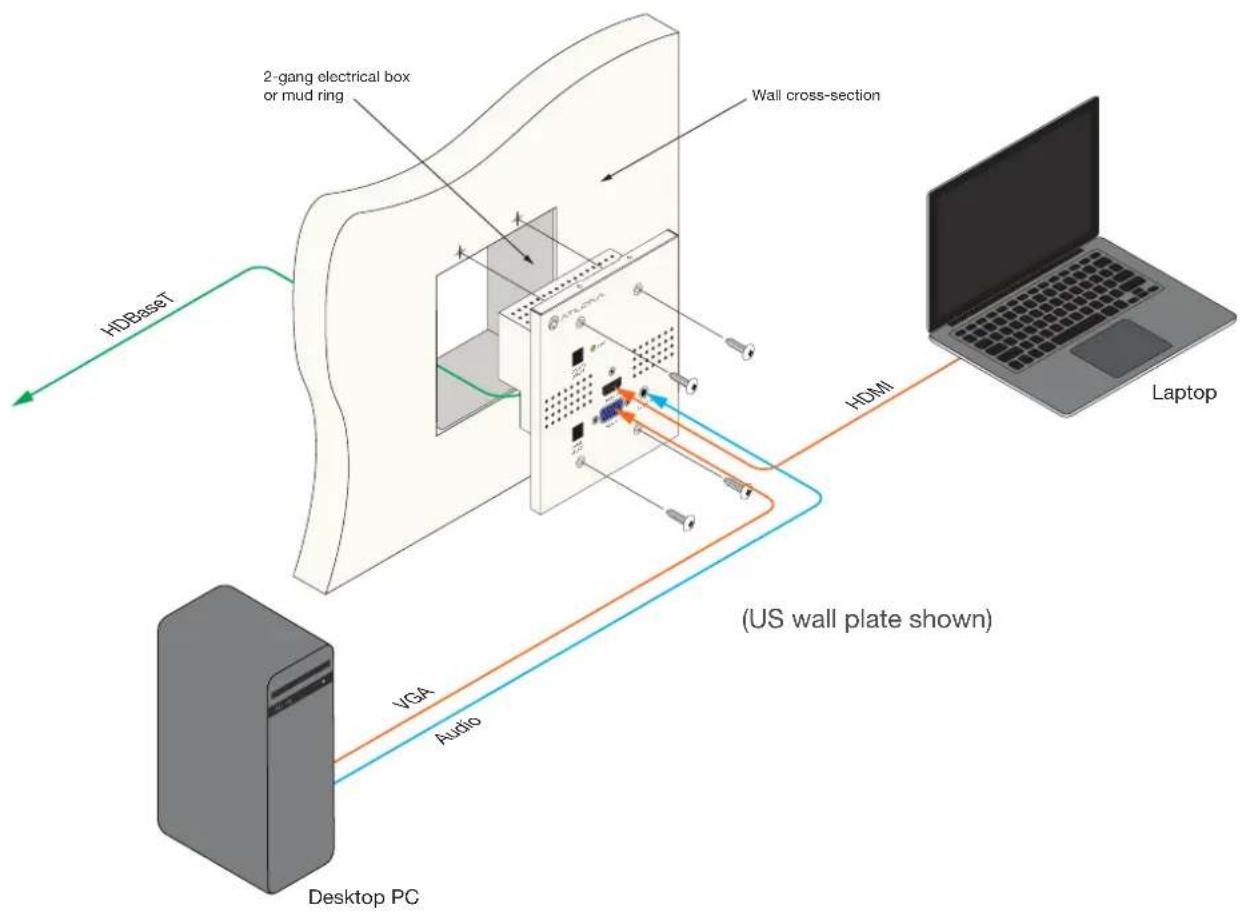
flowchart
graph TD
    A["Desktop PC"] -->|VGA Audio| B["Laptop"]
    B -->|HDMI| C["Wall cross-section"]
    C --> D["2-gang electrical box or mud ring"]
    D --> E["HDBaseT"]
    style A fill:#99ccff,stroke:#333
    style B fill:#ccc,stroke:#333
    style C fill:#fff,stroke:#333
    style D fill:#fff,stroke:#333
    style E fill:#fff,stroke:#333
Basic Operation
Powering the Display

NOTE: The following functionality and operation applies to both the AT-HDVS-150-TX-WP and AT-HDVS-150-TX-WP-UK.
When the AT-HDVS-150-TX-WP is connected to a compatible receiver and display, press the DISPLAY ON/OFF button to toggle the display's power state. When connected to a compatible Atlona receiver, the functionality of this button can be customized. Refer to the receiver's User Manual for more information.
Display powered on Display powered off


NOTE: When the display is in the "off" state, the DISPLAY ON/OFF button will glow bright blue. This functionality is added to assist in locating the wall plate in a darkened room.
Selecting the Input
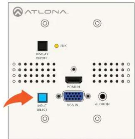
The INPUT SELECT button uses a bi-color LED to indicate the currently selected input. If power is interrupted to the wall plate, for any reason, the wall plate will always retain the last selected input. HDMI IN is the default input.
Press the INPUT SELECT button to toggle between HDMI IN and VGA IN. The color of the INPUT SELECT button will indicate which input is selected.
HDMI IN = blue VGA IN = red

Auto Switching
The AT-HDVS-150-TX-WP will automatically switch to the most recently-connected or powered source. For example, if both an HDMI and VGA source are connected and then the HDMI source is disconnected, the wall plate will automatically switch to the VGA IN port. The default setting is OFF and can be set using a compatible receiver.

NOTE: Auto-switching is triggered by a Hot-Plug Detect (HPD) event. If HPD is not detected, then AT-HDVS-150-TX-WP will not switch inputs. VGA does not support HPD.
Passing Analog Audio
Two-channel analog audio can be added to the VGA signal. In order for the audio to be passed to the receiver, an active VGA source must be connected to the VGA IN port and the port must be selected. Analog audio cannot be embedded on an HDMI signal or passed without a video signal on the VGA IN port.
- Connect a VGA source to the VGA IN port on the wall plate.
- Connect a 3.5 mm mini-stereo cable from the AUDIO IN port to the analog audio source.
- Make sure the VGA IN port is selected. When the VGA IN port is the active, the INPUT SELECT button will turn bright red.
The illustration below shows a desktop PC providing both the audio and video source. However, these signals may be connected to separate sources.

IMPORTANT: The AUDIO IN port will pass audio only when both the VGA IN port is selected and when the VGA IN port is connected to an active VGA source. Audio cannot be passed without video.

Appendix
Updating the Firmware

NOTE: The following firmware update procedure applies to both the AT-HDVS-150-TX-WP and AT-HDVS-150-TX-WP-UK.
Requirements
• AT-HDVS-150-TX-WP-US or AT-HDVS-150-TX-WP-UK
- Firmware file: AT-HDVS-150-TX_[version].bin
• USB Type A to Mini-USB Type B cable
• Computer with USB port
- Download the latest firmware from the Atlona web site.
- Remove the AT-HDVS-150-TX-WP from the wall, or other surface, by removing the four screws from the front of the wall plate.
- Disconnect the power to the AT-HDVS-150-TX-WP by disconnecting the Ethernet cable from the HDBaseT OUT port on the AT-HDVS-150-TX-WP.
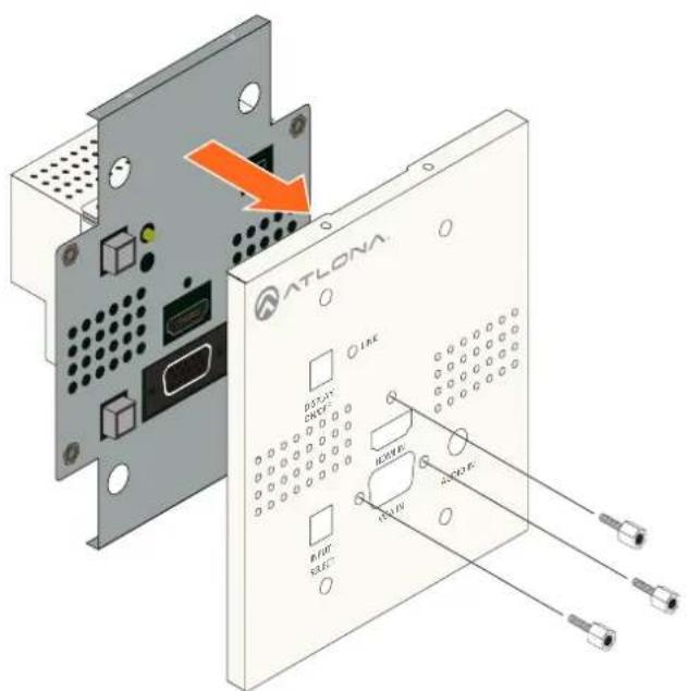
- Remove the faceplate from the front of the AT-HDVS-150-TX-WP, by unscrewing the two locking connectors for the VGA IN port and the locking connector for the HDMI IN port, using a small hex driver or pliers.

Appendix
- Press and hold the DISPLAY ON/OFF button, while connecting the USB cable from the computer to the mini-USB port on the AT-HDVS-150-TX-WP.

- After a few seconds, a folder with the name USB UPDATER, will be displayed. Release the DISPLAY ON/OFF button.
If the folder is not displayed, open Windows Explorer and locate the drive named USB UPDATER.

- Delete all files from the USB drive, if any are present.
- Drag-and-drop the AT-HDVS-150-TX_[version].bin firmware file to the drive.
- After the file has been copied, disconnect the USB cable from both the computer and the AT-HDVS-150-TX-WP.
- Reconnect the Ethernet cable to the HDBaseT OUT port on the AT-HDVS-150-TX-WP.
- The firmware update process is complete.
- Attach the faceplate then reinstall the AT-HDVS-150-TX-WP.
Specifications
| Video | |
| HD/SD 4096×2160@24/25/30/50+/60Hz*, 3840×2160@24/25/30/50*/60Hz*, 2048×1080p,1080p@23.98/24/25/29.97/30/50/59.94/60Hz, 1080i@50/59.94/60Hz,720p@50/59.94/60Hz, 576p, 576i, 480p, 480i | |
| VESA 2560×2048, 2560×1600, | 2048×1536, 1920×1200, 1680×1050, 1600×1200,1600×900, 1440×900, 1400×1050, 1366×768, 1360×768, 1280×1024, 1280×8001280×768, 1152×768, 1024×768, 800×600, 640×480 |
| Color Space YUV, RGB | |
| Chroma Subsampling 4:4:4, 4:2:2, 4:2:0* | |
| Color Depth 8-bit, 10-bit, 12-bit | |
| Audio | |
| Analog In PCM 2Ch | |
| HDMI In / HDBaseT Out PCM 2Ch | |
| Sample Rate 32 kHz, 44.1 kHz, 48 kHz, 88.2 kHz, 96 kHz, 176.4 kHz, 192 kHz | |
| Bit Rate 24-bit (max.) | |
| Resolution / Distance 4K/UHD - Feet / Meters 1080p - Feet / Meters | ||||
| HDMI 15 5 30 10 | ||||
| CAT-5e / CAT-6 | 115 | 35 | 197 | 60 |
| CAT-6a / CAT-7 | 130 | 40 | 230 | 70 |
| Signal | |
| Bandwidth | 10.2 Gbps |
| HDCP | 1.4 |
| Temperature | Fahrenheit | Celsius |
| Operating | 32 to 122 | 0 to 50 |
| Storage | -4 to 140 | -20 to 60 |
| Humidity (RH) | 20% to 90%, non-condensing |
Appendix
| Power | |
| Consumption 18.7 W (when paired) | |
| Dimensions Inches Millimeters | ||
| Wall, 2-gang 1.5 40 | ||
| Weight Pounds Kilograms | ||
| Device 0.82 0.37 | ||
| Certification | |
| Unit CE, FCC |
*4096x2160 @ 50/60 Hz and 3840x2160 @ 50/60 Hz supports 8-bit 4:2:0 choma subsampling, only.
Index
A
Audio
analog audio 12
AUDIO IN port 9
Auto switching 12
C
Connection
diagram 10
instructions 10
Contents
package 8
Customer support 3
D
DISPLAY ON/OFF
button 9,11
F
Faceplate
removing 13
FCC statement 6
Features 8
Firmware
updating 13
H
HDBaseT OUT
port 9
HDMI IN
port 9
Hot-Plug Detect 12
|
INPUT SELECT
button 9,11
Installation 10
L
LINK
indicator 9
O
Operating notes 3
P
Panel descriptions 9
S
Safety information 6
Specifications 15
Switching
auto 12
auto-switching 12
inputs 11
V
VGA IN
port 9, 11
W
Wall plate
installing 10
power 10
Warranty 4
- Wall Plate Switcher for HDMI and VGA with HDBaseT™ Output
- Version Information
- Welcome to Atlona!
- Sales, Marketing, and Customer Support
- Main Office
- International Headquarters
- Operating Notes
- Atlona, Inc. ("Atlona") Limited Product Warranty
- Coverage
- OR
- Coverage Periods
- Limited Product Warranty Terms - New Products
- Limited Product Warranty Terms - Refurbished (B-Stock) Products and Discontinued Products
- Remedy
- Exclusions
- Disclaimers
- Limitation on Liability
- Exclusive Remedy
- Other Conditions
- Important Safety Information
- CAUTION
- FCC Statement
- Table of Contents
- Introduction
- Features
- Package Contents
- Panel Description
- INPUT SELECT
- DISPLAY ON/OFF
- LINK
- HDMI IN
- AUDIO IN
- VGA IN
- HDBaseT OUT
- Installation
- Connection Instructions
- Connection Diagram
- Basic Operation
- Powering the Display
- Selecting the Input
- Auto Switching
- Passing Analog Audio
- Appendix
- Updating the Firmware
- Requirements
- Index
- A
- C
- D
- F
- H
- |
- L
- O
- P
- S
- V
- W
Brand : Atlona
Model : AT-HDVS-150-TX-WP-UK
Category : Audio/video converter