
FSM-X - Flat Screen Mount Gabor - Free user manual and instructions
Find the device manual for free FSM-X Gabor in PDF.


| Product Type | Flat Screen Mount / Bracket |
| Brand | Gabor |
| Model | FSM-X |
| Compatible Screen Sizes | Most 26" to 55" flat screens |
| VESA Compatibility | 200x200 to 400x400 mm |
| Weight Capacity | Up to 50 kg (110 lbs) |
| Material | High-grade steel with anti-corrosion coating |
| Color | Black |
| Adjustability | Swivel: ±15°, Tilt: up to 10°, Level adjustment |
| Fixation Type | Wall mount (stud or concrete wall) |
| Distance from Wall | Approximately 50-80 mm |
| Installation Kit Included | Screws, wall anchors, spacers, and instruction manual |
| Cable Management | Integrated cable clips to organize wires |
| Security Features | Anti-tilt bracket, locking screws to prevent theft |
| Maintenance | Wipe with a dry cloth; do not use solvents |
| Warranty | 2 years against manufacturing defects |
| Repairability | Spare parts available (screws, brackets) – contact support |
| General Notes | Ensure wall can support 4x the weight. Check for electrical wires before drilling. |
Frequently Asked Questions - FSM-X Gabor
User questions about FSM-X Gabor
0 question about this device. Answer the ones you know or ask your own.
Ask a new question about this device
Download the instructions for your Flat Screen Mount in PDF format for free! Find your manual FSM-X - Gabor and take your electronic device back in hand. On this page are published all the documents necessary for the use of your device. FSM-X by Gabor.
USER MANUAL FSM-X Gabor
natural_image
Technical line drawing of a mechanical assembly with mounting brackets and a vertical rail, featuring no visible text or symbols.FSM-L AND FSM-X / FULL SWING
MOUNT
for Large and Extra-Large Flat-Panel Displays
User Manual
Thank you for choosing Gabor.
This Cabor Full-Swing Wall Mount offers flexible mounting and customizable viewing angles for wall-mounted TVs and monitors. It accommodates large and extra-large flat-panel displays with screen sizes measuring 40 to 90 inches. The sturdy steel construction supports a maximum weight of 143 to 165 pounds. These mounts offer post-installation adjustments for tilt, swivel, pan, screen depth, and horizontal level so you can easily set up and comfortably view your display.
If you have safety concerns about installing this product, contact a qualified professional or installation contractor.
If this product is missing hardware or there are defective parts, visit www.madebygabor.com or call Customer Service at 212-594-2353.
Safety Warnings
- When installing this product, be sure to refer to the mounting instructions detailed in this manual; failure to abide by the mounting instructions may void the product's warranty.
- Do not use this product for any flat-panel display other than what it is intended for; the exact specification, size parameters, and weight limits are found both on the product box and in the instruction manual.
- It is strongly recommended that this product be installed by a qualified professional or installation contractor; Gabor takes no responsibility for any product damage or personal injury resulting from mishandling, incorrect mounting, faulty assembly, or improper use of this product.
- This product has been designed specifically for mounting directly on wooden studs or concrete walls; depending on wall type and material, the use of additional appropriate mounting hardware and/or accessories such as heavy-duty anchors may be required.
-
The supplied mounting hardware is not intended for use on metal studs or cinder block walls, and may not be appropriate for old or weak walls; it is best to consult with a qualified professional to determine whether your wall is capable of supporting this bracket.
-
Do not mount the device on structures that may be affected by vibrations or noticeable impacts; do not install near a heater, fireplace, or any other source of direct heat energy.
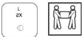
- It is recommended that at least 2 people perform the installation process to prevent injury from mishandling or dropping the product and/or flat-screen device.
- This product may contain small parts which can possibly pose a choking hazard; keep out of reach of children and pets.
- Excessive exposure to liquids may damage the finish of this product; when cleaning this product, use only a mild detergent solution, and quickly wipe dry with a soft cloth.
- All images are for illustrative purposes only.
Product Specifications
Depth from Mounting Source
2.7 to 25 in. (6.9 to 63.5 cm)
Recommended Screen Sizes
FSM-L: 40 to 70 in. (101.6 177.8 cm)
FSM-X: 60 to 90 in. (152.4 to 228.6 cm)
VESA Mounting Patterns
FSM-L: 200×200 mm
300×300 mm
400×200 mm
400×400 mm
600×400 mm
FSM-X: 200×200 mm
300×300 mm
400×200 mm
400×400 mm
600×400 mm
800×400 mm
Max Weight Capacity
FSM-L: 143 lb. (65 kg)
FSM-X: 165 lb. (74.8 kg)
Material
Steel
Weight
FSM-L: 22.6 lb. [10.26 kg]
FSM-X: 24.8 lb. (11.24 kg)
Overview
Wall bracket
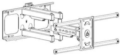
natural_image
Technical line drawing of a mechanical assembly with frame, shafts, and mounting brackets (no text or symbols)Display brackets
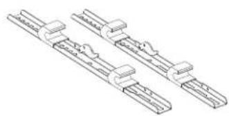
natural_image
Technical line drawing of two mechanical clamping components (no text or symbols)| ABCD | M5×10 mm screw, M5×30 mm screw, M5×10 mm screw, M4×30 mm screw. | 4×4×4×4×4× | E | F | G 8×4×H 8× | Large pixels |
| IJK6xSTS×50 mminchon screws | L6x13×50 mmchondorscrew | 4xDSonberscrewwarders | 2xThunbrowe | M 1xWall booklet, compact | N 1xFrical circuit | O 1xBubble level |
Required Tools
Drill

Phillips
SCREWDER
Hammer
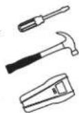
Tape measure

1/4 in. (6 mm)
Wood or ll bit
1/2 n. [12 mm]
Concrete drill bit
Pencil

Display/TV Placement
Before installing the Gabor Full Swing Mount, you will need to determine the placement of your display and identify surrounding support structures for attachment.
The best height for a display is at the viewer's eye level. You can find this height in one of two ways.
- Measure the distance from the seating area to the viewing area. The ideal position is when the center of the display (where the diagonals meet) is as close as possible to eye level.
OR - Cut a piece of sturdy cardboard that's approximately the same size as your display. Use the cardboard to find a comfortable height, and mark the mounting location with a pencil.

Attaching the Display Brackets
Selecting the Right VESA Mounting Hardware for Your Display
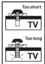
A variety of screws are included to fit VESA standards on the backs of most displays. Select the M5, M6, or M8 screws and washers that best fit your display. Hand-thread the screws to determine the correct diameter.
Install the brocket directly to your display.


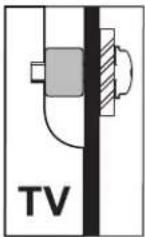
If Your Display Has Recessed Mounting or a Curved Back:
Install the spacers between the bracket and your display. You can combine spacers to best fit your display. Then fasten with the screws and washers until secure.


natural_image
Mechanical assembly diagram showing a tool inserted into a housing with a screw and a base component (no text or labels)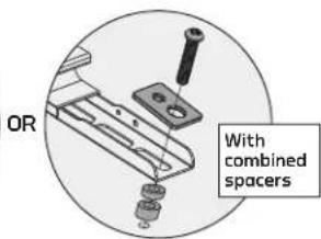
Attaching the Wall Bracket to Wooden Studs
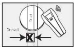
Wooden studs run vertically inside the wall, 15 inches apart, behind the drywall or plaster. The wall brocket must be mounted to a wooden stud, or the brocket could fall out and damage your display or cause personal harm.

- Use a stud finder to locate the edges of the wooden stud, and mark the center.
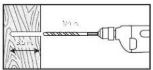
- Use a 1/4-inch (6 mm) wood drill bit to predrill the four anchor locations as shown, 3.5 inches (90 mm) deep, and then clean out the debris from the holes.
- Place the wall bracket template up to the marked locations, and tape is to the wall. Use the provided bubble level to make sure the template is level before drilling. Use a pencil to mark the four locations as shown, and place a piece of tape over each mark.

natural_image
Technical line drawing of a rectangular frame with internal components and mounting holes (no text or symbols)- Remove the template, and screw only the top two anchor screws into the wall, leaving a 5 mm gap between the wall and screw's head.

natural_image
Technical diagram showing a wooden panel with two vertical supports and a close-up view of a wooden post (no text or symbols)Attaching the Wall Bracket to Wooden Studs (cont.)
- Seat the wall bracket onto the two anchor screws, using the two seating holes.

-
Screw in the top two anchor screws the rest of the way until secure. Use the wrench to further tighten the anchor screws, but do not overtighten.
-
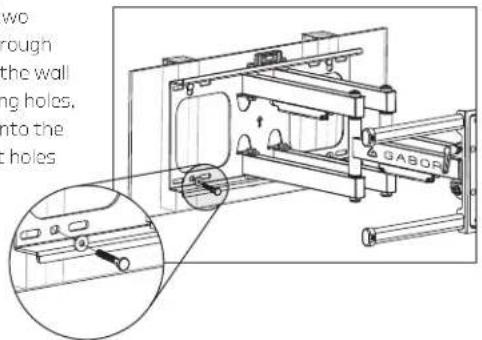
Insert the bottom two anchor screws through the washers and the wall brackets' mounting holes, and screw them into the predrilled support holes until secure.
natural_image
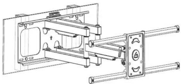
Technical line drawing of a mechanical assembly with mounting brackets and railings (no text or symbols)Wall bracket mounted to wooden stud, with correct screw placement.
Attaching the Wall Bracket to Concrete
Warning! Make sure the concrete wall is solid and at least 8 inches (20 cm) thick. If the concrete exhibits cracks or other defects, this may result in failure of the concrete anchors and cause serious personal injury or damage to your display.
-
Place the wall bracket template up to the marked locations, and tape it to the wall. Use the provided bubble level to make sure the template is level before drilling. Use a pencil to mark the six locations as shown, and place a piece of tape over each mark.
-
Use a 1/2-inch (12 mm) concrete drill bit to predrill the marked spots 3.7 inches (95 mm) deep, and then clean out the debris from the holes.

natural_image
3D diagram of a rectangular block with labeled X and Y axes, showing internal structure and arrows (no text or symbols)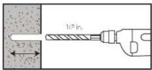

- Remove the template, and insert the concrete anchors into the predrilled holes. Use a hammer to top the anchors into the concrete.

- Screw in the top two anchor screws that correspond to the wall bracket's seating holes, and leave a 5 mm gap between the wall and the screw's head.

natural_image
3D diagram of a rectangular block with four corner holes and an inset showing a cross-section with dimension 'R' (no text or symbols)Attaching the Wall Bracket to Concrete (cont.)
- Seat the wall bracket onto the two anchor screws using the two seating holes.

-
Screw in the first two anchor screws the rest of the way until secure. Use the wrench to further tighten the screws, but do not overtighten.
-
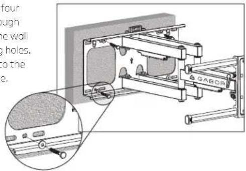
Insert the remaining four anchor screws through the washers and the wall brackets' mounting holes, and screw them into the anchors until secure.

natural_image
Technical line drawing of a mechanical assembly with labeled components (no readable text or symbols)Wall bracket mounted to concrete, with correct screw placement.
Mounting the Display on the Wall Bracket
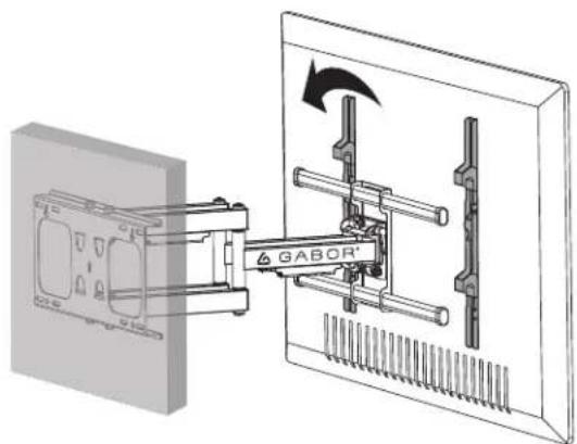
Important! We recommend that two people perform this step.
natural_image
Technical diagram showing a GABOR tool interacting with a wall-mounted device (no text or symbols present)- Lift your display up to the wall bracket's display bars, and hang the display from the hooks of the display brackets.

natural_image
Technical diagram of a mechanical assembly with a GABOR® component, showing internal components and a magnified inset (no text or symbols)- Flip up the display bracket latches, and screw in the thumbscrews until secure.
Post-Installation Adjustment
Once your display is mounted on the wall bracket, you can fine-tune the horizontal level, tilt, pivot, and depth from the wall.

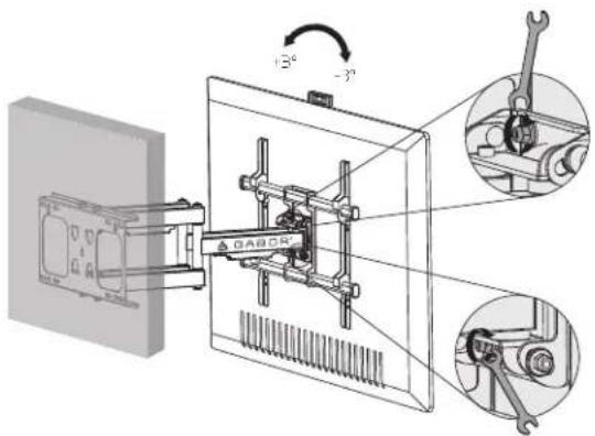
Horizontal Level
Loosen the four screws with the included crescent wrench as shown, and adjust the horizontal level +3° to -3°. Use the bubble level to make sure your display is level, and then tighten the screws until secure.

Tilt Angle
Loosen the ratchet handle, and tilt the display up or down 15^ to 15^ to fine-tune the viewing angle. Tighten the handle and screws as shown until secure.
Post-Installation Adjustment (cont.)

Display Pivot
Pivot your display up to 120° for flexible mouting in the corner of a room or around an object.
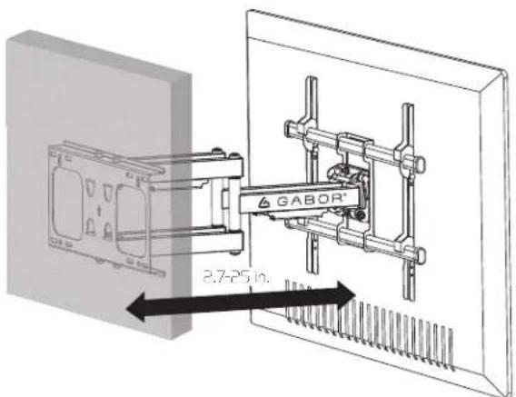
Display Depth
You can collapse or extend the mount so your display is 2.7 to 25 inches from the wall.
Cable Management
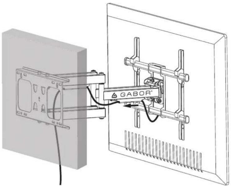
Run the power and A/V cables through cable concealment covers attached to the bottom of the mounting bracket extension arms. Widen the cover openings to slide the cables into the covers, and pull the cables through.
natural_image
Technical diagram of a GABOR device mounted on a wall-mounted panel, showing wiring and connection (no text or symbols present)Five-Year Limited Warranty
This Gabor product is warranted to the original purchaser to be free from defects in materials and workmanship under normal consumer use for a period of five (5) years from the original purchase date or thirty (30) days after replacement, whichever occurs later. The warranty provider's responsibility with respect to this limited warranty shall be limited solely to repair or replacement, at the provider's discretion, of any product that foils during normal use of this product in its intended manner and in its intended environment. Inoperability of the product or part(s) shall be determined by the warranty provider. If the product has been discontinued, the warranty provider reserves the right to replace it with a model of equivalent quality and function.
This warranty does not cover damage or defect caused by misuse, neglect, accident, alteration, abuse, improper installation or maintenance. EXCEPT AS PROVIDED HEREIN, THE WARRANTY PROVIDER MAKES NEITHER ANY EXPRESS WARRANTIES NOR ANY IMPLIED WARRANTIES, INCLUDING BUT NOT LIMITED TO ANY IMPLIED WARRANTY OF MERCHANTABILITY OR FITNESS FOR A PARTICULAR PURPOSE. This warranty provides you with specific legal rights, and you may also have additional rights that vary from state to state.
To obtain warranty coverage, contact the Gabor Customer Service Department to obtain a return merchandise authorization ("RMA") number, and return the defective product to Gabor along with the RMA number and proof of purchase. Shipment of the defective product is at the purchaser's own risk and expense.
For more information or to arrange service, visit www.madebygabor.com or call Customer Service at 212-594-2353.
Product warranty provided by the Gradus Group.
www.grodusgroup.com
Gabor is a registered trademark of the Gradus Group. © 2020 Gradus Group LLC. All Rights Reserved.

GABOR®
A Gradus Group Brand
- MOUNT
- Thank you for choosing Gabor.
- Safety Warnings
- Product Specifications
- Depth from Mounting Source
- Recommended Screen Sizes
- VESA Mounting Patterns
- Max Weight Capacity
- Material
- Weight
- Overview
- Required Tools
- Display/TV Placement
- Attaching the Display Brackets
- Selecting the Right VESA Mounting Hardware for Your Display
- If Your Display Has Recessed Mounting or a Curved Back:
- Attaching the Wall Bracket to Wooden Studs
- Attaching the Wall Bracket to Wooden Studs (cont.)
- Attaching the Wall Bracket to Concrete
- Attaching the Wall Bracket to Concrete (cont.)
- Mounting the Display on the Wall Bracket
- Post-Installation Adjustment
- Horizontal Level
- Tilt Angle
- Post-Installation Adjustment (cont.)
- Cable Management
- Five-Year Limited Warranty
Brand : Gabor
Model : FSM-X
Category : Flat Screen Mount