
BLT1 - Flat Screen Mount SANUS - Free user manual and instructions
Find the device manual for free BLT1 SANUS in PDF.


| Product Type | Flat panel TV wall mount |
| Brand | Sanus |
| Model | BLT1 |
| Compatible Screen Sizes | 26" to 55" |
| Maximum Weight Capacity | 80 lbs (36.3 kg) |
| VESA Compatibility | 100x100 to 400x400 mm |
| Mount Type | Fixed low-profile mount |
| Distance from Wall | 1.5 inches (38 mm) |
| Leveling Adjustment | ±1.5° |
| Material | High-grade steel |
| Included Hardware | All necessary mounting hardware, bubble level, and template |
| Installation Type | Two-person recommended, stud mounting |
| Care and Cleaning | Wipe with a dry or slightly damp cloth; avoid abrasive cleaners |
| Safety Certification | UL-listed, tested to 4x weight capacity |
| Spare Parts Availability | Contact Sanus customer service for replacement parts |
| Repairability | Not user-serviceable; professional installation recommended |
| Warranty | 5-year limited warranty |
| Package Dimensions | 16.5 x 12.5 x 3.0 inches |
| Package Weight | 6.5 lbs (2.95 kg) |
Frequently Asked Questions - BLT1 SANUS
User questions about BLT1 SANUS
0 question about this device. Answer the ones you know or ask your own.
Ask a new question about this device
Download the instructions for your Flat Screen Mount in PDF format for free! Find your manual BLT1 - SANUS and take your electronic device back in hand. On this page are published all the documents necessary for the use of your device. BLT1 by SANUS.
USER MANUAL BLT1 SANUS
natural_image
Painting of a vibrant sunset over rolling hills with colorful sky and clouds, no text or symbols visibleTHANK YOU FOR CHOOSING SANUS THE #1 TV MOUNT BRAND IN THE US.
BLT1 Instruction Manual
Scan for easy install video

SANUS MAGNETIC STUD FINDER
Designed to find your studs and make life easier—included in hardware kit.

TWO SIMPLE STEPS TO FINDING YOUR STUDS:

flowchart
graph TD
    A["Top Tank"] --> B["Bottom Tank"]
    B --> C["Top Tank"]
    style A fill:#999
    style B fill:#ccc
    style C fill:#fff
    subgraph Section 1
        D["Section 1"]
        E["Section 2"]
        F["Section 3"]
        G["Section 4"]
        H["Section 5"]
        I["Section 6"]
        J["Section 7"]
        K["Section 8"]
        L["Section 9"]
        M["Section 10"]
        N["Section 11"]
        O["Section 12"]
        P["Section 13"]
        Q["Section 14"]
        R["Section 15"]
        S["Section 16"]
        T["Section 17"]
        U["Section 18"]
        V["Section 19"]
        W["Section 20"]
        X["Section 21"]
        Y["Section 22"]
        Z["Section 23"]
        AA["Section 24"]
        AB["Section 25"]
        AC["Section 26"]
        AD["Section 27"]
        AE["Section 28"]
        AF["Section 29"]
        AG["Section 30"]
        AH["Section 31"]
        AI["Section 32"]
        AJ["Section 33"]
        AK["Section 34"]
        AL["Section 35"]
        AM["Section 36"]
        AN["Section 37"]
        AO["Section 38"]
        AP["Section 39"]
        AQ["Section 40"]
        AR["Section 41"]
        AS["Section 42"]
        AT["Section 43"]
        AU["Section 44"]
        AV["Section 45"]
        AW["Section 46"]
        AX["Section 47"]
        AY["Section 48"]
        AZ["Section 49"]
        BA["Section 50"]
        BB["Section 51"]
        BC["Section 52"]
        BD["Section 53"]
        BE["Section 54"]
        BF["Section 55"]
        BG["Section 56"]
        BH["Section 57"]
        BI["Section 58"]
        BJ["Section 59"]
        BK["Section 60"]
        BL["Section 61"]
        BM["Section 62"]
        BN["Section 63"]
        BO["Section 64"]
        BP["Section 65"]
        BQ["Section 66"]
        BR["Section 67"]
        BS["Section 68"]
        BT["Section 69"]
        BU["Section 70"]
        BV["Section 71"]
        BW["Section 72"]
        BX["Section 73"]
        BY["Section 74"]
        BZ["Section 75"]
        CA["Section 76"]
        CB["Section 77"]
        CC["Section 78"]
        CD["Section 79"]
        CE["Section 80"]
        CF["Section 81"]
        GD["Section 82"]
        DH["Section 83"]
        DI["Section 84"]
        DJ["Section 85"]
        DK["Section 86"]
        DL["Section 87"]
        DV["Section 88"]
        DW["Section 89"]
        DX["Section 90"]
        DXB["Section 91"]
        DXC["Section 92"]
        DXD["Section 93"]
        DXE["Section 94"]
        DXF["Section 95"]
        DXG["Section 96"]
        DXH["Section 97"]
        DXI["Section 98"]
        DXJ["Section 99"]
    end
Holding it vertically, lightly move the SANUS Magnetic Stud Finder up and down while sliding across your wall. The magnet within will be attracted to the screws in the stud.
Once the magnet has landed on a screw, place a pencil mark on the wall directly below the magnet.
You can verify this is a stud by moving the Magnetic Stud Finder up or down to find a second or third screw within the wall.
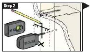
Pull apart the SANUS Magnetic Stud Finder to expose the probing pin within. Starting about y_2 inch away from the first pencil mark insert the probing pin into the wall every 1/8 inch until it inserts completely into the wall. Once that happens, you know you've found one edge of your stud. Repeat this process till you have found the stud edges and center of the stud.
WARNING: This product contains a magnet. If an implanted medical device such as a pacemaker or implantable cardioverter defibrillator (ICD) is in use, magnetic fields may affect the operation of those devices, resulting in serious injury or death. If you have an implanted medical device, keep at least 13 cm (5in.) between your device and the magnet. Please consult with your physician or medical professional prior to using this product.
natural_image
Technical line drawing of a mechanical clamp or bracket assembly with labeled component 'BLT1' (no other text or symbols)We'll Make It Stress-Free
If you have any questions along the way, just give us a call. 1-800-359-5520 (UK: 0800-056-2853) We're ready to help!
IMPORTANT SAFETY INSTRUCTIONS – SAVE THESE INSTRUCTIONS – PLEASE READ ENTIRE MANUAL PRIOR TO USE
Before getting started, let's make sure this mount is perfect for you!
Does your TV weigh (including accessories) more than 175 lbs. (79.3 kg)?

No — Perfect!
Yes — This mount is NOT compatible. Visit MountFinder.Sanus.com or call 1-800-359-5520 (UK: 0800-056-2853) to find a compatible mount.
2
What is your wall made of?



Call Customer Service: 1-800-359-5520 (UK: 0800-056-2853)
3
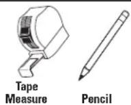
Do you have all the tools needed?


4
Ready to begin?
Please read through these instructions completely to be sure you're comfortable with this easy install process. Also check your TV owner's manual to see if there are any special requirements for mounting your TV.
If you do not understand these instructions or have doubts about the safety of the installation, assembly or use of this product, contact Customer Service at 1-800-359-5520 (UK: 0800-056-2853).

CAUTION: Avoid potential personal injuries and property damage!
- This product includes directions and hardware for use with wood stud, solid concrete and concrete block walls – DO NOT install into drywall alone.
- The wall must be capable of supporting five times the weight of the TV and mount combined.
- Do not use this product for any purpose not explicitly specified by manufacturer.
● Manufacturer is not responsible for damage or injury caused by incorrect assembly or use.
STEP 1
Attach Brackets to TV
Parts and Hardware for STEP 1
⚠ WARNING: This product contains small items that could be a choking hazard if swallowed.
Before starting assembly, verify all parts are included and undamaged. If any parts are missing or damaged, do not return the damaged item to your dealer; contact Customer Service. Never use damaged parts!

NOTE: Not all hardware included will be used.

TV Screws
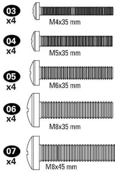


1.1 Select TV Screws
Hand thread screws into the threaded inserts on the back of your TV to determine which screw diameter (M4, M5, M6, or M8) to use.

CAUTION: Verify adequate thread engagement of the screw/washer/spacer combination on your TV.
Too short will not hold the TV and too long will damage the TV.

Too Short Correct Too Long
1.2 Spacers
Spacers and screws are supplied to install your TV bracket.
Determine your preference for spacer configuration when attaching your TV bracket.

Mount the spacers 09 above the TV bracket, for flat back panels (AND the TV closer to the wall).

Mount the spacers 09 under the TV bracket to create extra space needed for irregular shape TV backs or large cables.
Round Back CablesInset HolesFlat Back


If your TV included inset spacers or wall mount adapters, see Troubleshooting on PAGE 24.

1.3 Attach TV Brackets
Center the TV brackets 01 and 02 over your TV hole pattern as shown - making sure the brackets are level.

NOTE: The tilt tension knob Ⓣ on TV brackets 01 and 02 should be oriented to the outside edges.
Install using the spacer, TV screw and washer combination you selected for your TV.
CAUTION: Avoid potential personal injuries and property damage! DO NOT use a power screwdriver for this step. Tighten screws only until TV Bracket is secured in place. DO NOT overtighten M4 screws 03.

Standard configurations are shown. For special applications, or if you are uncertain about your hardware selection, contact Customer Service at 1-800-359-5520.

STEP 2A Attach Wall Plate to Wall
Parts and Hardware for STEP 2
WARNING: This product contains small items that could be a choking hazard if swallowed.
Before starting assembly, verify all parts are included and undamaged. If any parts are missing or damaged, do not return the damaged item to your dealer; contact Customer Service. Never use damaged parts!
* ⚠ WARNING: This product contains a magnet. If an implanted medical device such as a pacemaker or implantable cardioverter defibrillator (ICD) is in use, magnetic fields may affect the operation of those devices, resulting in serious injury or death. If you have an implanted medical device, keep at least 13 cm (5 in.) between your device and the magnet. Please consult with your physician or medical professional prior to using this product.

NOTE: Not all hardware included will be used.

For concrete installations ONLY

STEP 2A

Stud Option
CAUTION: Avoid potential personal injuries and property damage!
- Drywall covering the wall must not exceed 5/8 in. (16 mm)
- Minimum wood stud size: common 2 x 4 in. (51 x 102 mm) nominal 1½ x 3½ in. (38 x 89 mm)
• Minimum horizontal space between fasteners: 16 in. (406 mm) -
Stud centers must be verified – not all walls have conventional 16 in. (406 mm) or 24 in. (610 mm) stud spacing
-
Locate a nail/screw in the studs using the Sanus magnetic stud finder 13 provided.
- Find the edges of the studs using the probe of the stud finder 13.
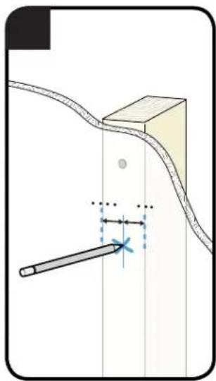
- Mark the centers of the studs with a pencil.


natural_image
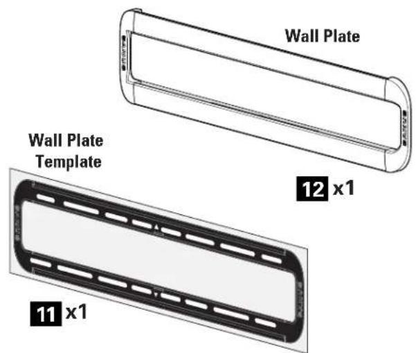
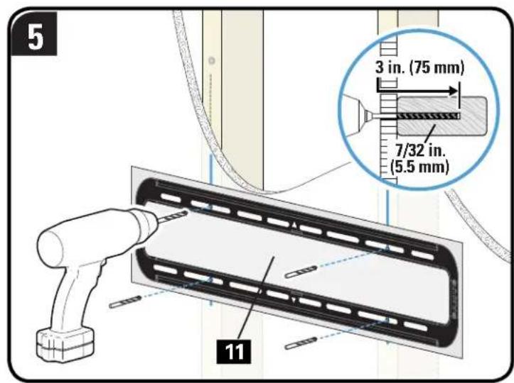
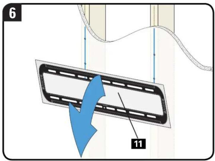
Diagram showing a tool interacting with a curved surface and vertical lines, no text or symbols present- Place the wall plate template 11 at your desired height and position the slotted holes over your stud center lines. Level the wall plate template 11 and tape in place.

NOTE: For assistance in determining wall plate location, see HeightFinder at sanus.com.
IMPORTANT: Be sure you mark and drill into the center of the stud.
- Drill the four pilot holes using a 7/32 in. (5.5 mm) diameter drill bit.
IMPORTANT: Pilot holes must be drilled to a depth of 3 in. (75 mm).

- Remove the wall plate template

- Slide the covers

open on the wall plate 12 to expose the mounting holes.
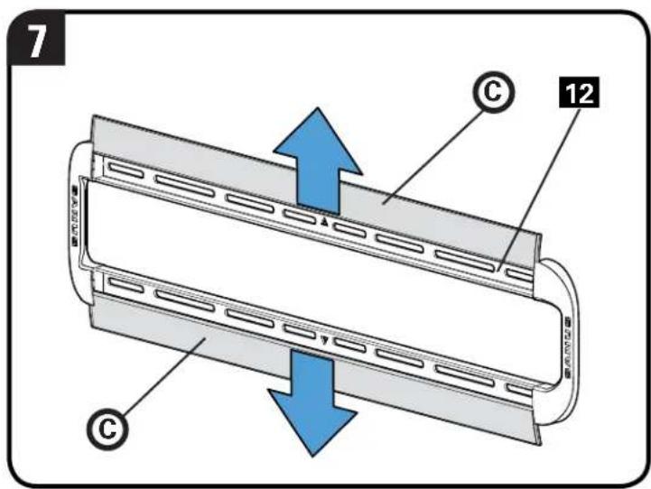
- Install the wall plate 12 using four lag bolts 14. Firmly tighten all four lag bolts 14 until they are pulled flush against the wall plate 12.

NOTE: Hold the wall plate 12 in place when tightening the first lag bolt 14 to keep the plate from shifting out of place.
CAUTION: Avoid potential personal injury or property damage! All four lag bolts 14 MUST BE firmly tightened to prevent unwanted movement of the wall plate 12. Ensure the wall plate is securely fastened to the wall before continuing on to the next step.
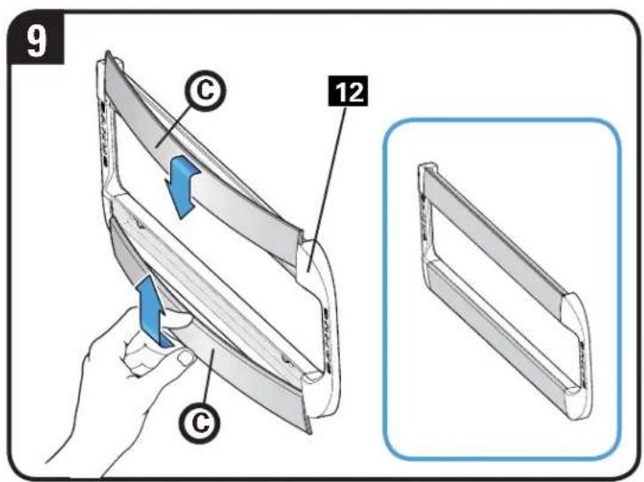
- Slide the covers

closed on wall plate 12.
Go to STEP 3 on PAGE 16.

STEP 2B

Concrete or Concrete Block Option
CAUTION: Avoid potential personal injuries and property damage!
-
Mount the wall plat 12 directly onto the concrete surface
• Minimum solid concrete thickness: 8 in. (203 mm)
• Minimum concrete block size: 8 x 8 x 16 in. (203 x 203 x 406 mm)
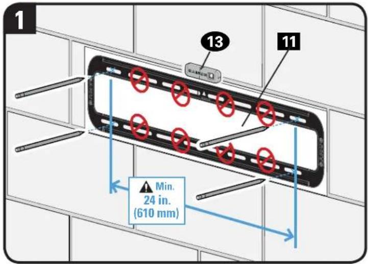
• Minimum horizontal space between fasteners: 24 in. (610 mm) -
Position the wall plate template 11 on the wall at your desired height. Level the wall plate template and mark the hole locations.

NOTE: For assistance in determining wall plate location, see Height Finder at sanus.com.
- Drill four pilot holes using a 3/8 in. (10 mm) diameter drill bit.
IMPORTANT: Pilot holes must be drilled to a depth of 3 in. (75 mm). Never drill into the mortar between blocks.
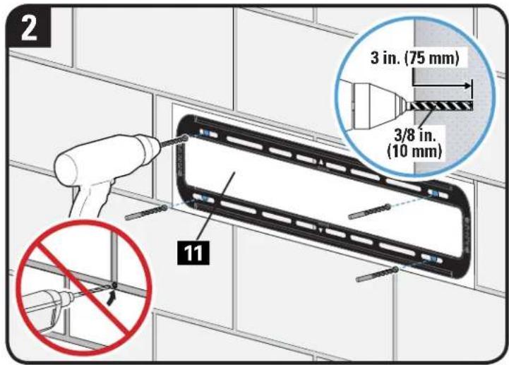
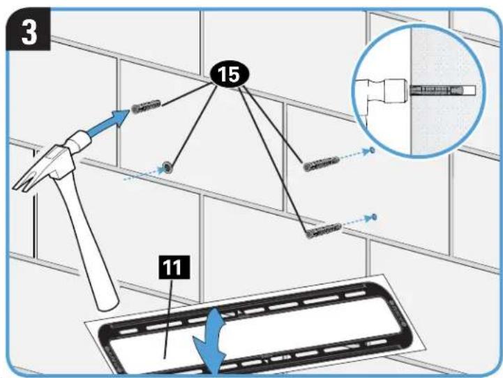
- Remove the wall plate template 11 and insert four anchors 15.
CAUTION: Be sure the anchors 15 are seated flush with the concrete surface.
- Slide the covers Ⓐ open on the wall plate 12 to expose the mounting holes.

- Install the wall plate 12 using four lag bolts 14. Firmly tighten all four lag bolts 14 until they are pulled flush against the wall plate 12.

NOTE: Hold the wall plate 12 in place when tightening the first lag bolt 14 to keep the plate from shifting out of place.
CAUTION: Avoid potential personal injury or property damage! All four lag bolts 14 MUST BE firmly tightened to prevent unwanted movement of the wall plate 12. Ensure the wall plate is securely fastened to the wall before continuing on to the next step.
- Slide the covers © closed on wall plate 12.


STEP 3
Attach TV to Wall Plate

HEAVY! You may need assistance with this step.
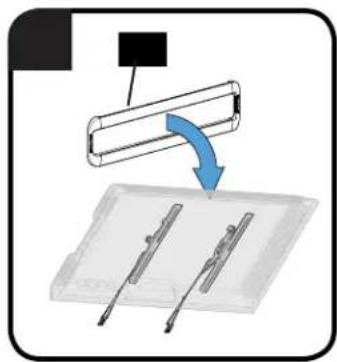
- Hook the TV brackets 01 and 02 onto the wall plate 12.
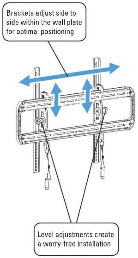
NOTE: The TV brackets 01 and 02 can be slid anywhere along the wall plate 12 for optimal positioning of your TV.
-
Rest the TV into place against the wall.
-
Press the bottom of the TV into the wall plate 12 until the latches lock the TV in place.
CAUTION: Avoid potential personal injury or property damage! Always make sure your TV brackets are in the locked position so the TV is securely fastened to the wall plate 12.


natural_image
Technical diagram of a mechanical lifting device with a blue arrow indicating motion direction (no text or symbols)
natural_image
Diagram of a helicopter inside a device with a lock and gear mechanism, no text or symbols presentManage Cables
Tilt the TV up or down to gain access to the back of the TV. Attach your cables, then adjust the TV as desired.

Adjustments

LEVEL Tilt
To level your TV, turn the level adjustment screw Ⓢ on the top of either TV bracket 01 or 02 to raise or lower that respective side of the TV.

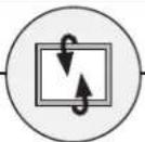
Your TV should adjust easily when moved, then stay in place.
Adjust the tilt tension knob Ⓣ if your TV naturally tilts up or down.
NOTE: If you do not intend to adjust the tilt for different viewing locations, you can tighten the tilt tension knobs Ⓣ to prevent unwanted movement.


TV LATERAL SHIFT

REMOVING THE TV

HEAVY! You may need assistance with this step.
Slide the TV left or right along the wall plate 12 to reposition.


HEAVY! You may need assistance with this step.
-
Disconnect all cables from the TV.
-
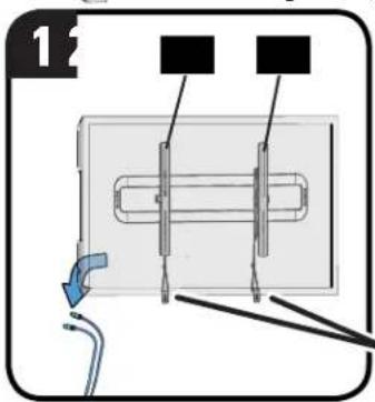
To unlock the TV from the wall plate: Pull down and hold both release cords while gently pulling the bottom of the TV away from the wall.
CAUTION: Avoid potential personal injury or property damage! To prevent breaking the locking latch: always pull and hold the release cords down while pulling the TV away from the wall.
- Lift the TV up and off of wall plate 12.
NOTE: To rehang the TV, follow the procedures in STEP 3 on PAGE 16.

natural_image
Diagram showing a mechanical assembly with a cylindrical component and two parallel rods, one with a blue arrow indicating rotation (no text or symbols present)
Troubleshooting
TV supplied spacers
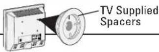
a: Use your TV supplied spacer for flat back TVs (AND you want your TV closer to the wall).

CAUTION: Avoid potential injury or property damage! Use the correct screw length for adequate thread engagement.
- Too short will not hold the TV.
- Too long will damage the TV.
▲ Too Short
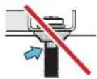
▲ Too Long

Correct

If you are uncertain about your hardware selection, contact Customer Service at 1-800-359-5520.
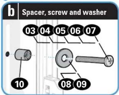
b: Use your TV supplied spacer and spacer 10 for:
• Round (irregular) back TVs
- Extra space needed for cables
ROUND BACK CABLES


natural_image
Technical illustration of three mechanical components: a wheel, a cylindrical shaft, and a bolt (no text or symbols)TV Supplied Spacer

CAUTION: Avoid potential injury or property damage! Use the correct screw length for adequate thread engagement.
- Too short will not hold the TV.
- Too long will damage the TV.


Features


Dimensions
in. [mm]
TV INTERFACE
![26.58 [675.0] 7.88 [200.0] 16.24 [412.5] 8.96 [227.5] 0.49 [12.5]](/content/2026/05/983951/images/423de3e47b63a63f699fd6ec609c8c3050bcc9245a404f810a226ebb72307c1b.jpg)
WALL PLATE
![30.88 [784.3] 11.21 [284.7] 6.88 [74.6] 1.33 [33.9] 7.25 [184.2] 2.68 [68.1] 1.73 [44.0] 3.90 [99.1] 29.21 [742.0] 6.47 [164.4]](/content/2026/05/983951/images/d69e6823ec43b5c781c3d1dd47b98ab3a81453d4ecee14c0608a868117de77c7.jpg)
FULLY ASSEMBLED MOUNT

natural_image
Pure mechanical diagram of a cylindrical object with two vertical supports and a base, no text or symbols present.
NOTE: The offset hole pattern on right TV bracket 02 is designed to accommodate a better range of TV hole patterns, while allowing proper engagement with the wall plate.
TOP VIEW - EXTENDED

TOP VIEW - RETRACTED

3-D

natural_image
Pure mechanical linkage diagram without any text, numbers, or symbolsSIDE VIEW - EXTENDED
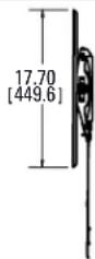
SIDE VIEW - RETRACTED
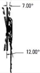
ESPAÑOL
INSTRUCCIONES DE SEGURIDAD IMPORTANTES. CONSERVELAS. LEA TODO EL MANUAL ANTES DE UTILIZAR ESTE PRODUCTO.
Milestone AV Technologies and its affiliated corporations and subsidiaries (collectively, "Milestone"), intend to make this manual accurate and complete. However, Milestone makes no claim that the information contained herein covers all details, conditions, or variations. Nor does it provide for every possible contingency in connection with the installation or use of this product. The information contained in this document is subject to change without notice or obligation of any kind. Milestone makes no representation of warranty, expressed or implied, regarding the information contained herein. Milestone assumes no responsibility for accuracy, completeness or sufficiency of the information contained in this document.
Learn ways to get the most out of your space. Find product updates and more.
TWITTER.COM/SANUSSYSTEMS

Learn installation tips, tricks and household know-hows.
View step-by-step product videos to ease your install experiences. Find the latest news stories about your favorite SANUS products.
REGISTER YOUR NEW SANUS PRODUCT!
1 By registering, you'll be entered to win, and will receive the latest product updates, design tips, and other ways to enhance your life in your home.
2 Visit SANUS.com/register to complete your registration and start enjoying all of the benefits SANUS has to offer.
3 Leave a product review and let us know how your install went! ★★★★★
If you ever have questions about your SANUS product, give us a call at 1-800-359-5520. We're ready to help! 'Monthly prize' rules and restrictions apply. Visit SANUS.com for more info.
800-359-5520 (UK: 0800-056-2853) • info@sanus.com • sanus.com
©2015 Milestone AV Technologies. All rights reserved. SANUS is a division of Milestone. All other brand names or marks are used for identification purposes and are trademarks of their respective owners.
SANUS • 6436 City West Parkway • Eden Prairie, MN 55344 USA
6901-002525 00

- SANUS MAGNETIC STUD FINDER
- TWO SIMPLE STEPS TO FINDING YOUR STUDS:
- We'll Make It Stress-Free
- IMPORTANT SAFETY INSTRUCTIONS – SAVE THESE INSTRUCTIONS – PLEASE READ ENTIRE MANUAL PRIOR TO USE
- Before getting started, let's make sure this mount is perfect for you!
- 2
- 3
- 4
- STEP 1
- Attach Brackets to TV
- Parts and Hardware for STEP 1
- Select TV Screws
- Spacers
- Attach TV Brackets
- STEP 2A Attach Wall Plate to Wall
- Parts and Hardware for STEP 2
- STEP 2A
- Stud Option
- CAUTION: Avoid potential personal injuries and property damage!
- STEP 2B
- Concrete or Concrete Block Option
- STEP 3
- Attach TV to Wall Plate
- Manage Cables
- Adjustments
- LEVEL Tilt
- Troubleshooting
- TV supplied spacers
- Features
- Dimensions
- ESPAÑOL
- INSTRUCCIONES DE SEGURIDAD IMPORTANTES. CONSERVELAS. LEA TODO EL MANUAL ANTES DE UTILIZAR ESTE PRODUCTO.
- REGISTER YOUR NEW SANUS PRODUCT!
Brand : SANUS
Model : BLT1
Category : Flat Screen Mount