
BLT2 - Flat Screen Mount SANUS - Free user manual and instructions
Find the device manual for free BLT2 SANUS in PDF.


| Product Type | Flat Panel Wall Mount |
| Brand | Sanus |
| Model | BLT2 |
| Compatible Screen Sizes | 26" to 47" |
| Maximum Weight Capacity | 125 lbs (56.7 kg) |
| VESA Compatibility | 100x100mm to 400x400mm |
| Tilt Adjustment | +10° / -5° |
| Profile Distance from Wall | 1.5" (38mm) |
| Mount Type | Fixed (low profile) |
| Material | Rugged steel construction |
| Color | Black |
| Installation | Includes hardware and template |
| Level Adjustment | Post-installation micro-adjustments |
| Safety Features | Safety release tab, security screws |
| Cleaning | Wipe with a dry cloth |
| Spare Parts Availability | Contact Sanus support |
| Repair Service | Contact authorized service center |
| Package Contents | Mount, hardware pack, manual |
| Certifications | UL listed |
Frequently Asked Questions - BLT2 SANUS
User questions about BLT2 SANUS
0 question about this device. Answer the ones you know or ask your own.
Ask a new question about this device
Download the instructions for your Flat Screen Mount in PDF format for free! Find your manual BLT2 - SANUS and take your electronic device back in hand. On this page are published all the documents necessary for the use of your device. BLT2 by SANUS.
USER MANUAL BLT2 SANUS
Follow this step-by-step instruction manual to speed up your installation.
WE'RE HERE TO HELP

natural_image
Person holding a black rectangular device with a white play button, no visible text or symbolsWant to watch a video that shows how easy this DIY project will be?

Get it right the first time. HeightFinder™ shows you where to drill.

natural_image
Group of professionals in an office environment, one wearing a headset and smiling (no visible text or symbols)Our US-based install experts are standing by to help.

Watch it now at: SANUS.com/2513

Check it out at: SANUS.com/1172

Call us at: 800-359-5520

Or, chat at: SANUS.com/chatSP
IMPORTANT SAFETY INSTRUCTIONS
PLEASE READ ENTIRE MANUAL PRIOR TO USE – SAVE THESE INSTRUCTIONS
Please read through these instructions completely to be sure you're comfortable with this easy install process.
Check your TV owner's manual to see if there are any special requirements for mounting your TV.
If you do not understand these instructions or have doubts about the safety of the installation, assembly or use of this product, contact Customer Service.
CAUTION: Avoid potential personal injuries and property damage!
- This product is designed ONLY to be installed into wood stud, solid concrete or concrete block or steel stud walls. — DO NOT INSTALL INTO DRYWALL ALONE — DRYWALL ALONE WILL NOT HOLD THE WEIGHT OF YOUR TV.
- This product is designed for INDOOR USE ONLY.
- The wall must be capable of supporting five times the weight of the TV and mount combined.
- Do not use this product for any purpose not explicitly specified by manufacturer.
● Manufacturer is not responsible for damage or injury caused by incorrect assembly or use.
TV Weight Limit (including accessories)
DO NOT EXCEED

For wood stud and Solid Concrete or Concrete Block Walls
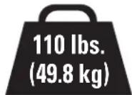
For Steel
Stud Walls
If your TV, plus accessories, weighs MORE than indicated, this mount is NOT compatible.
Visit SANUS.com or call customer service to find a compatible mount.
Wall Construction
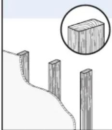
ONLY install on these acceptable wall types.

Unsure
Call Customer Service
CAUTION:
DO NOT install in drywall alone
Drywall alone will NOT hold the weight of your TV.

wood studs
natural_image
Illustration of wooden posts with a curved path and a magnified inset showing a rectangular block (no text or symbols)ACCEPTABLE A
Solid concrete or concrete block

natural_image
Illustration of a brick wall with an inset showing a close-up of a block (no text or symbols present)CEPTABLE
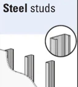
Steel stud kit SSMK1 is required for install, but NOT INCLUDED. Call Customer Service
Tools Needed

Measure

Pencil Level Tape


ScrewdriverTape
Electric Drill

Socket Wrench


Stud Finder
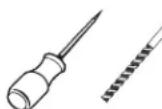
Awl Awl

Drill Bit Drill Bit


Hammer

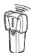
Stud Finder

Dimensions in. [mm]
TV INTERFACE
![[200mm] 7.57in [400mm] 16.93in [600mm] 22.42in](/content/2026/05/983950/images/fedd40f597e85cc77cbad14e3be62fb1ed57a8255aa61f144ebfbcc5a90c8059.jpg)
TOP VIEW - EXTENDED
![[144.8mm] 5.70in](/content/2026/05/983950/images/e10c47742b8f57e6d4aaf4222994da2ec056340519965841f7bf8d01bcb41502.jpg)
SIDE VIEW - EXTENDED

WALL PLATE
![[609.4mm] 24.00in [600mm] 23.62in [406.4mm] 16.03in [241.3mm] 9.53in [5.4mm] Ø.33in [77.8mm] 7.00in [450mm] 17.72in [668mm] 26.30in [762mm] 30.00in](/content/2026/05/983950/images/0f1131401161033746e2ce6cef7ab35c9113ba1093b6e6d44a8d0d9da9e89360.jpg)
TOP VIEW - RETRACTED

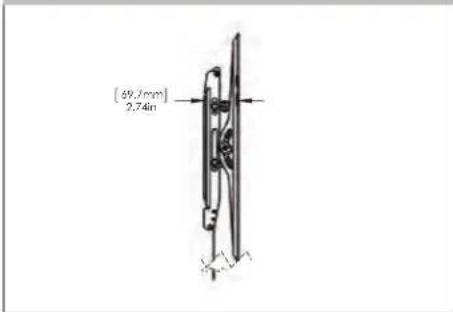
SIDE VIEW - RETRACTED
3-D
![SANUS BLT2 - Dimensions in. [mm] - 7](/content/2026/05/983950/images/fa268adf2ee29b5999491a52385038dc205b0edf8fb2c4af7790c78ba41975ca.jpg)
natural_image
Technical line drawing of a mechanical clamp or bracket assembly (no text or symbols)FULLY ASSEMBLED MOUNT
![[460mm] 18.1in [323.5mm] 12.73in [760mm] 30.03in](/content/2026/05/983950/images/00c36e1668bf9759e228bfd99a2395870e05b224e91361d302c5bd3d36c4eee9.jpg)
BEFORE YOU BEGIN
Remove the stand from your TV — if attached.
Install any accessories you may have purchased, if they require TV removal prior to assembly. The TV is removable for future accessory purchases.
Protect the face of your TV when laying it down for installation.

natural_image
Diagram showing a device with a black arrow pointing to a mechanical component (no text or symbols present)
natural_image
Diagram showing a device with an arrow indicating direction, no text or symbols present
ATTACH TV BRACKET TO TVSTEP 1
Parts and Hardware for STEP 1

WARNING: This product contains small items that could be a choking hazard if swallowed. Before starting assembly, verify all parts are included undamaged. If any parts are missing or damaged, do not return the damaged item to your dealer; contact Customer Service. Never use damaged parts!

NOTE: Not all hardware included will be used.

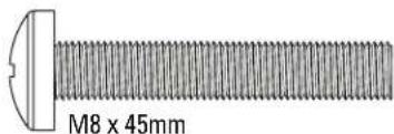
TV Screws
(qty. 4 each)
[Only one size fits your TV]
M6


M8




Washers
(qty. 4 each)

M6/M8 M6/M8

Spacers
[If necessary] (qty. 4 each)

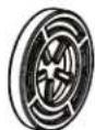


TV Bracket
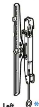
natural_image
Mechanical device with vertical bars and a labeled 'Left' section (no text or symbols on the device itself)Left TV Bracket
04(qty.1)

TV Bracket
05 (qty. 1)

CAUTION: Avoid potential
personal injury or property damage!
The TV brackets contain pinch points during operation. Keep fingers away from pinch points when retracting the TV. (arrows)

1.1 Select TV Screw Diameter
Only one screw size fits your TV.
M6
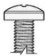
M8

O


NOTE: If your TV
included inset spacers or adapters, use them UNDER the mount hardware.

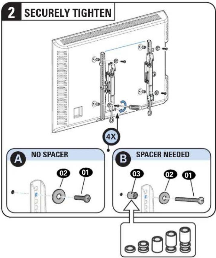
1.2 Select TV Screw Length / Spacers

NO SPACER SPACER N B ED
- Flat Back TV
[TV brackets lay flat on your TV]
Use short TV screws 01
Spacers 03 not needed.

- Flat Back TV with Extra Space Needed [for deep inset holes or cable interference]
Use long TV screws 01 and spacers 03 to create extra space between the TV and TV bracket.
• Rounded or Irregular Back TV [TV brackets NOT resting flat on your TV]

Inset Holes


natural_image
Diagram of a device with an arrow pointing to a component, showing internal structure and mounting points (no text or symbols present)⚠️ CAUTION: Verify adequate thread engagement
with your screw 01, washer 02, spacer 03
combination AND TV bracket 04/05
— Too short will not hold your TV.
— Too long will damage your TV.
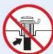
Too Short

Too Long

Correct

1.3 Attach TV Bracket Assembly to TV
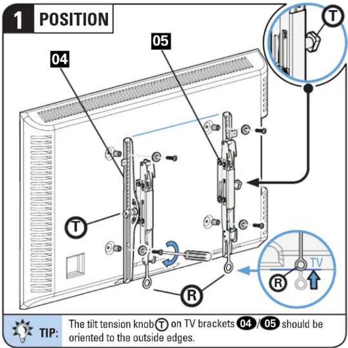
STEP 2
ATTACH WALL PLATE TO WALL
Parts and Hardware for STEP 2
WARNING: This product contains small items that could be a choking hazard if swallowed. Before starting assembly, verify all parts are included and undamaged. If any parts are missing or damaged, do not return the damaged item to your dealer, contact Customer Service. Never use damaged parts!

NOTE: Not all hardware included will be used.

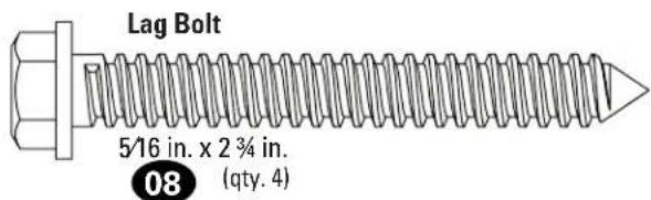

For concrete installations ONLY

STEP 2A

Wood Stud Installation
CAUTION: Avoid potential personal injury or property damage!
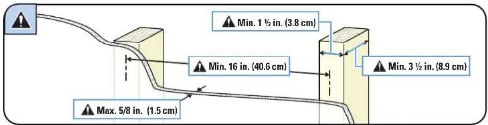
- Drywall covering the wall must not exceed 5/8 in. (1.5 cm)
• Minimum wood stud size: nominal 2 x 4 in. (5.1 x 10.2 cm) actual 1 ½ x 3 ½ in. (3.8 x 8.9 cm)
• Minimum horizontal space between fasteners:16 in. (40.6 cm)
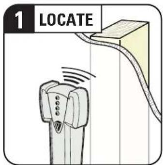
• Stud centers must be verified


![4 POSITION TEMPLATE Visit HeightFinder™ sanus.com /1172 4X 06 TIP: To calculate your precise wall plate location, check out our HeightFinder at sanus.com [www.sanus.com/1172].](/content/2026/05/983950/images/df679f174573eddaff62a856b87ecd21c0dbc3d87f479cbfbb4824b27de15d87.jpg)

STEP 2B

Solid Concrete or Concrete Block Installation
CAUTION: Avoid potential personal injury or property damage!
- Mount the wall plate 07 directly onto the concrete surface
• Minimum solid concrete thickness: 8 in. (20.3 cm)
• Minimum concrete block size: 8 x 8 x 16 in. (20.3 x 20.3 x 40.6 cm)
• Minimum horizontal space between fasteners: 16 in. (40.6 cm) - For concrete applications, TV brackets 04/05 must remain centered in wall plate 07. Keep this in mind when selecting the wall plate location
![1 POSITION TEMPLATE Visit HeightFinder™ sanus.com /1172 4X Min. 16 in. (40.6 cm) TIP: To calculate your precise wall plate location, check out our HeightFinder at sanus.com [www.sanus.com/1172]](/content/2026/05/983950/images/9244fc1fe812f160fde27a3375fbf163a5b14e3a8848bc46bbb6b2a36a45a3dc.jpg)



STEP 2C

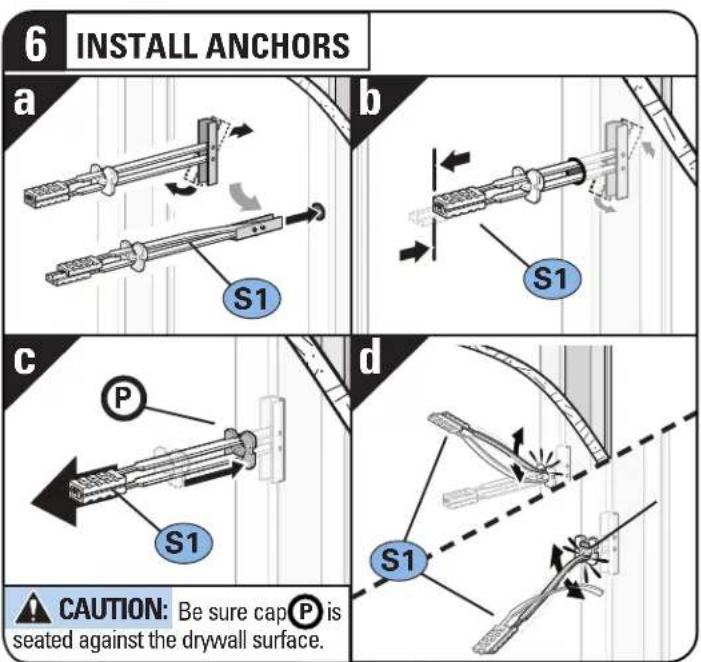
Steel Stud Installation
CAUTION: Avoid potential personal injury or property damage!
• Studs must be at least 2x4 / 25 ga.
- If back side of wall is unfinished, drywall must be installed to a minimum of one stud left and right of the stud(s) being used to install the mount
- Drywall must be a minimum of 1/2 in. (13 mm) thick on each side of the studs, and a minimum clearance of 1 18 in. (48 mm) behind the wall is required
• This product must be centered on the studs
- Stud type and structural strength must conform to the North American Specification for the Design of Cold-Formed Steel Structural Members [362 S 125 18, C-Shape, S - Stud Section]
- Drywall must be secured to studs with screws 12 in. (304.8 mm) on center


TIP:
To calculate your precise wall plate location, check out our Height Finder at sanus.com [www.san.us/1172].
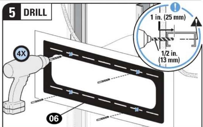

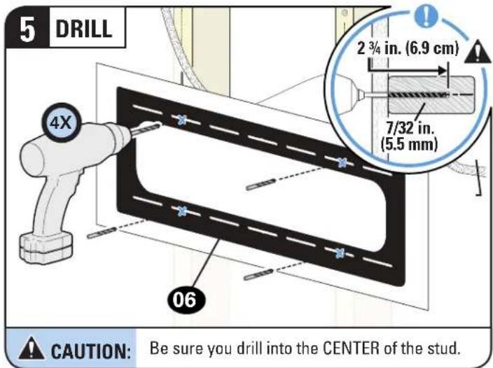
CAUTION: Be sure you drill into the CENTER of the stud.


CAUTION: Avoid potential personal injury or property damage!
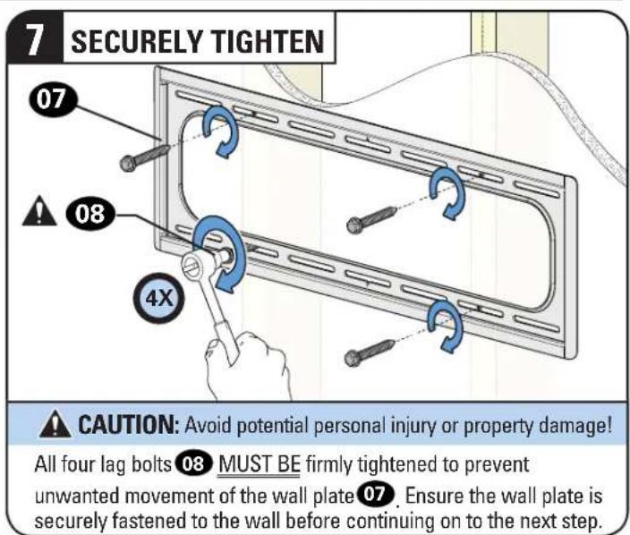
All four screws S2 MUST BE firmly tightened to prevent unwanted movement of the wall plate 07. Ensure the wall plate is securely fastened to the wall before continuing on to the next step.
CAUTION: Avoid potential personal injury or property damage!
For CONCRETE APPLICATIONS:
TV brackets 04 / 05 MUST remain centered in wall plate 07.

NOTE: For WOOD STUD APPLICATIONS, TV brackets 04 / 05 can solid anywhere along wall plate 07 for optimal positioning of your TV.

CAUTION: Avoid potential personal injury or property damage!
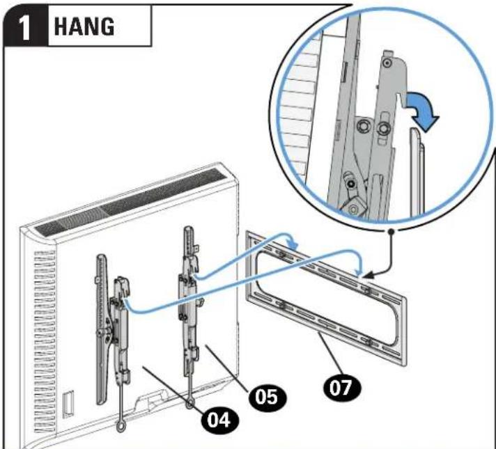
Always make sure TV brackets 04 / 05 are in the locked position so the TV is securely fastened to the wall plate 07.
MANAGE CABLES


TIP: Extend the TV outward AND tilt the TV up or down to gain better access to the back of the TV.
ADJUSTMENTS

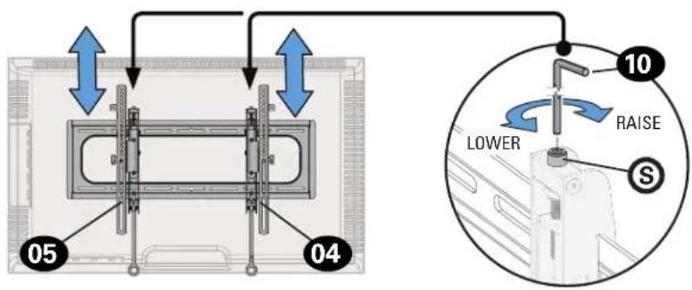
LEVEL
To level your TV, turn the level adjustment screw S on the top of either TV bracket 04 / 05 to raise or lower that respective side of the TV.


HEIGHT
Adjust the height by turning the level adjustment screw Ⓢ on the top of both TV brackets 04 / 05.

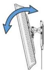
TILT
Your TV should adjust easily when moved, then stay in place. Adjust the tilt tension knob ☑ if your TV naturally tilts up or down.

NOTE: If you do not intend to adjust the tilt for different viewing locations, you can tighten the tilt tension knobs to prevent unwanted movement.


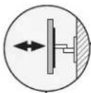
EXTEND

RETRACT

CAUTION: Avoid potential
personal injury or property damage!
The TV brackets contain potential pinch points during operation. Keep fingers away from pinch points when retracting the TV. (see arrows)

natural_image
Diagram of a mechanical clamp or bracket assembly with red arrows indicating direction (no text or symbols present)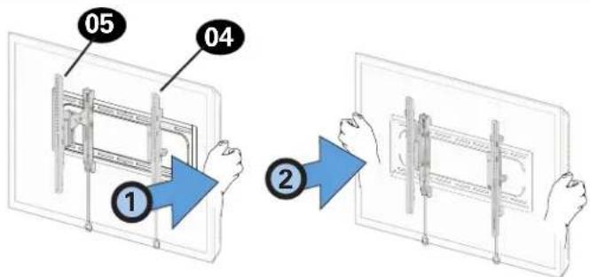

SIDE-TO-SIDE SHIFT

HEAVY! You may need assistance with this step.

CAUTION: Avoid potential personal injury or property damage!
For concrete applications, TV brackets 04 / 05 must remain centered in wall plate 07.
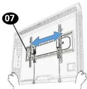
For Wood Stud Installations ONLY: Slide the TV left or right along the wall plate 07 to reposition.
REMOVING THE TV
- Disconnect all cables.
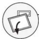
- To unlock the TV from the wall plate: Pull down and hold both release tabs ☑ while gently pulling the bottom of the TV away from the wall.

CAUTION: Avoid potential personal or property damage!
To prevent breaking the locking latch: always pull and hold the release tabs down while pulling the TV away from the wall.
- Lift the TV up and off of wall plate 07.

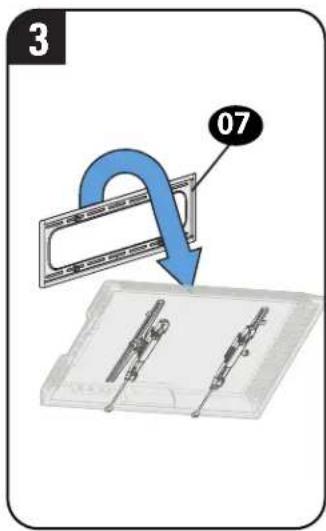
NOTE: To rehang the TV, follow the cedures in STEP 3 on PAGE 9.

HEAVY! You may need assistance with this step.


ESPAÑOL
Kit SSMK1 (not included)
Register your new mount to make the most of your SANUS warranty.
Visit SANUS.com to register now— it takes 25 seconds!
natural_image
Modern living room interior with leather sofa, white furniture, and large TV displaying a cityscape (no visible text or symbols)When you share your handiwork with your friends, tag
sanusspaces
for a chance to be featured on SANUS.com

@sanussystems

SanusSystems

pinterest.com/SANUS

SanusSystems
800-359-5520 • info@sanus.com • SANUS.com SANUS • 6436 City West Parkway • Eden Prairie, MN 55344 USA ©Legrand AV, Inc
6901-602560 00

- WE'RE HERE TO HELP
- IMPORTANT SAFETY INSTRUCTIONS
- PLEASE READ ENTIRE MANUAL PRIOR TO USE – SAVE THESE INSTRUCTIONS
- CAUTION: Avoid potential personal injuries and property damage!
- TV Weight Limit (including accessories)
- DO NOT EXCEED
- Wall Construction
- CAUTION:
- Tools Needed
- Dimensions in. [mm]
- BEFORE YOU BEGIN
- ATTACH TV BRACKET TO TVSTEP 1
- Parts and Hardware for STEP 1
- TV Screws
- Select TV Screw Diameter
- Select TV Screw Length / Spacers
- NO SPACER SPACER N B ED
- Attach TV Bracket Assembly to TV
- STEP 2
- ATTACH WALL PLATE TO WALL
- Parts and Hardware for STEP 2
- For concrete installations ONLY
- STEP 2A
- Wood Stud Installation
- CAUTION: Avoid potential personal injury or property damage!
- STEP 2B
- Solid Concrete or Concrete Block Installation
- STEP 2C
- Steel Stud Installation
- MANAGE CABLES
- ADJUSTMENTS
- LEVEL
- HEIGHT
- TILT
- EXTEND
- RETRACT
- SIDE-TO-SIDE SHIFT
- REMOVING THE TV
- ESPAÑOL
- sanusspaces
Brand : SANUS
Model : BLT2
Category : Flat Screen Mount